JP4866671B2 - Image forming apparatus - Google Patents
Image forming apparatus Download PDFInfo
- Publication number
- JP4866671B2 JP4866671B2 JP2006193028A JP2006193028A JP4866671B2 JP 4866671 B2 JP4866671 B2 JP 4866671B2 JP 2006193028 A JP2006193028 A JP 2006193028A JP 2006193028 A JP2006193028 A JP 2006193028A JP 4866671 B2 JP4866671 B2 JP 4866671B2
- Authority
- JP
- Japan
- Prior art keywords
- latent image
- image carrier
- rotation
- pattern
- fluctuation
- Prior art date
- Legal status (The legal status is an assumption and is not a legal conclusion. Google has not performed a legal analysis and makes no representation as to the accuracy of the status listed.)
- Expired - Fee Related
Links
- 238000012546 transfer Methods 0.000 claims description 251
- 238000001514 detection method Methods 0.000 claims description 155
- 238000012937 correction Methods 0.000 claims description 58
- 238000000034 method Methods 0.000 claims description 28
- 230000000737 periodic effect Effects 0.000 claims description 20
- 230000008569 process Effects 0.000 claims description 18
- 239000000463 material Substances 0.000 claims description 16
- 239000000969 carrier Substances 0.000 claims description 12
- 238000006073 displacement reaction Methods 0.000 claims description 9
- 230000002093 peripheral effect Effects 0.000 claims description 3
- 230000001678 irradiating effect Effects 0.000 claims description 2
- 238000012545 processing Methods 0.000 description 28
- 238000010586 diagram Methods 0.000 description 15
- 230000006870 function Effects 0.000 description 15
- 238000005070 sampling Methods 0.000 description 15
- 230000004048 modification Effects 0.000 description 14
- 238000012986 modification Methods 0.000 description 14
- 230000005540 biological transmission Effects 0.000 description 13
- 239000003086 colorant Substances 0.000 description 12
- 230000015572 biosynthetic process Effects 0.000 description 10
- 230000008859 change Effects 0.000 description 7
- 238000009826 distribution Methods 0.000 description 7
- 230000009467 reduction Effects 0.000 description 7
- 230000007246 mechanism Effects 0.000 description 6
- 238000004140 cleaning Methods 0.000 description 4
- 230000006866 deterioration Effects 0.000 description 4
- 230000000694 effects Effects 0.000 description 4
- 239000002131 composite material Substances 0.000 description 3
- 230000008878 coupling Effects 0.000 description 3
- 238000010168 coupling process Methods 0.000 description 3
- 238000005859 coupling reaction Methods 0.000 description 3
- 239000011521 glass Substances 0.000 description 3
- 238000003384 imaging method Methods 0.000 description 3
- 238000012423 maintenance Methods 0.000 description 3
- 230000003287 optical effect Effects 0.000 description 3
- 230000001360 synchronised effect Effects 0.000 description 3
- 238000012935 Averaging Methods 0.000 description 2
- 230000003111 delayed effect Effects 0.000 description 2
- 238000011161 development Methods 0.000 description 2
- 238000007599 discharging Methods 0.000 description 2
- 238000007689 inspection Methods 0.000 description 2
- 239000000314 lubricant Substances 0.000 description 2
- 238000011084 recovery Methods 0.000 description 2
- 230000007480 spreading Effects 0.000 description 2
- 238000003892 spreading Methods 0.000 description 2
- NAWXUBYGYWOOIX-SFHVURJKSA-N (2s)-2-[[4-[2-(2,4-diaminoquinazolin-6-yl)ethyl]benzoyl]amino]-4-methylidenepentanedioic acid Chemical compound C1=CC2=NC(N)=NC(N)=C2C=C1CCC1=CC=C(C(=O)N[C@@H](CC(=C)C(O)=O)C(O)=O)C=C1 NAWXUBYGYWOOIX-SFHVURJKSA-N 0.000 description 1
- 241000519995 Stachys sylvatica Species 0.000 description 1
- 230000009471 action Effects 0.000 description 1
- 230000008901 benefit Effects 0.000 description 1
- 230000015556 catabolic process Effects 0.000 description 1
- 238000006243 chemical reaction Methods 0.000 description 1
- 230000008602 contraction Effects 0.000 description 1
- 238000007796 conventional method Methods 0.000 description 1
- 125000004122 cyclic group Chemical group 0.000 description 1
- 230000007423 decrease Effects 0.000 description 1
- 238000006731 degradation reaction Methods 0.000 description 1
- 239000006185 dispersion Substances 0.000 description 1
- 239000000428 dust Substances 0.000 description 1
- 230000007613 environmental effect Effects 0.000 description 1
- 230000005484 gravity Effects 0.000 description 1
- 238000005286 illumination Methods 0.000 description 1
- 230000001050 lubricating effect Effects 0.000 description 1
- 238000005259 measurement Methods 0.000 description 1
- 230000010355 oscillation Effects 0.000 description 1
- 108091008695 photoreceptors Proteins 0.000 description 1
- 230000002441 reversible effect Effects 0.000 description 1
- 238000000926 separation method Methods 0.000 description 1
- 238000004904 shortening Methods 0.000 description 1
- 238000009751 slip forming Methods 0.000 description 1
- 230000002123 temporal effect Effects 0.000 description 1
Images


Classifications
-
- G—PHYSICS
- G03—PHOTOGRAPHY; CINEMATOGRAPHY; ANALOGOUS TECHNIQUES USING WAVES OTHER THAN OPTICAL WAVES; ELECTROGRAPHY; HOLOGRAPHY
- G03G—ELECTROGRAPHY; ELECTROPHOTOGRAPHY; MAGNETOGRAPHY
- G03G15/00—Apparatus for electrographic processes using a charge pattern
- G03G15/50—Machine control of apparatus for electrographic processes using a charge pattern, e.g. regulating differents parts of the machine, multimode copiers, microprocessor control
- G03G15/5054—Machine control of apparatus for electrographic processes using a charge pattern, e.g. regulating differents parts of the machine, multimode copiers, microprocessor control by measuring the characteristics of an intermediate image carrying member or the characteristics of an image on an intermediate image carrying member, e.g. intermediate transfer belt or drum, conveyor belt
- G03G15/5058—Machine control of apparatus for electrographic processes using a charge pattern, e.g. regulating differents parts of the machine, multimode copiers, microprocessor control by measuring the characteristics of an intermediate image carrying member or the characteristics of an image on an intermediate image carrying member, e.g. intermediate transfer belt or drum, conveyor belt using a test patch
-
- G—PHYSICS
- G03—PHOTOGRAPHY; CINEMATOGRAPHY; ANALOGOUS TECHNIQUES USING WAVES OTHER THAN OPTICAL WAVES; ELECTROGRAPHY; HOLOGRAPHY
- G03G—ELECTROGRAPHY; ELECTROPHOTOGRAPHY; MAGNETOGRAPHY
- G03G15/00—Apparatus for electrographic processes using a charge pattern
- G03G15/01—Apparatus for electrographic processes using a charge pattern for producing multicoloured copies
- G03G15/0105—Details of unit
- G03G15/0131—Details of unit for transferring a pattern to a second base
-
- G—PHYSICS
- G03—PHOTOGRAPHY; CINEMATOGRAPHY; ANALOGOUS TECHNIQUES USING WAVES OTHER THAN OPTICAL WAVES; ELECTROGRAPHY; HOLOGRAPHY
- G03G—ELECTROGRAPHY; ELECTROPHOTOGRAPHY; MAGNETOGRAPHY
- G03G2215/00—Apparatus for electrophotographic processes
- G03G2215/00025—Machine control, e.g. regulating different parts of the machine
- G03G2215/00029—Image density detection
- G03G2215/00059—Image density detection on intermediate image carrying member, e.g. transfer belt
-
- G—PHYSICS
- G03—PHOTOGRAPHY; CINEMATOGRAPHY; ANALOGOUS TECHNIQUES USING WAVES OTHER THAN OPTICAL WAVES; ELECTROGRAPHY; HOLOGRAPHY
- G03G—ELECTROGRAPHY; ELECTROPHOTOGRAPHY; MAGNETOGRAPHY
- G03G2215/00—Apparatus for electrophotographic processes
- G03G2215/01—Apparatus for electrophotographic processes for producing multicoloured copies
- G03G2215/0103—Plural electrographic recording members
- G03G2215/0119—Linear arrangement adjacent plural transfer points
- G03G2215/0122—Linear arrangement adjacent plural transfer points primary transfer to an intermediate transfer belt
- G03G2215/0125—Linear arrangement adjacent plural transfer points primary transfer to an intermediate transfer belt the linear arrangement being horizontal or slanted
- G03G2215/0132—Linear arrangement adjacent plural transfer points primary transfer to an intermediate transfer belt the linear arrangement being horizontal or slanted vertical medium transport path at the secondary transfer
-
- G—PHYSICS
- G03—PHOTOGRAPHY; CINEMATOGRAPHY; ANALOGOUS TECHNIQUES USING WAVES OTHER THAN OPTICAL WAVES; ELECTROGRAPHY; HOLOGRAPHY
- G03G—ELECTROGRAPHY; ELECTROPHOTOGRAPHY; MAGNETOGRAPHY
- G03G2215/00—Apparatus for electrophotographic processes
- G03G2215/01—Apparatus for electrophotographic processes for producing multicoloured copies
- G03G2215/0151—Apparatus for electrophotographic processes for producing multicoloured copies characterised by the technical problem
- G03G2215/0158—Colour registration
- G03G2215/0161—Generation of registration marks
Landscapes
- Physics & Mathematics (AREA)
- General Physics & Mathematics (AREA)
- Engineering & Computer Science (AREA)
- Microelectronics & Electronic Packaging (AREA)
- Control Or Security For Electrophotography (AREA)
- Color Electrophotography (AREA)
- Discharging, Photosensitive Material Shape In Electrophotography (AREA)
- Electrostatic Charge, Transfer And Separation In Electrography (AREA)
Description
本発明は、複写機、ファクシミリ、プリンタ等の画像形成装置に関するものである。 The present invention relates to an image forming apparatus such as a copying machine, a facsimile, and a printer.
複写機やプリンタあるいはファクシミリなどの画像形成装置には、潜像担持体上に形成した潜像にトナーを付与して可視化し、得られたトナー像を記録材に転写するか、又はトナー像を中間転写体を介して記録材に転写するかして、画像を形成するものがある。このような画像形成装置としては、互いに異なる複数色の単色画像を互いに重ね合わせることでカラー画像を得るものが知られている。このようなカラー画像形成装置においては、近年、高画質化および高速化が要求されている。かかる要求に応え得るカラー画像形成装置としては、例えば、各感光体ドラム(潜像担持体)上にそれぞれ形成した黒(K),イエロー(Y),マゼンタ(M),シアン(C)の各単色画像を、記録材搬送ベルト(表面移動部材)に担持搬送される記録材上へ互いに重なり合うように転写することで記録材上へカラー画像を形成する直接転写方式のタンデム型画像形成装置が知られている。 In an image forming apparatus such as a copying machine, a printer, or a facsimile, a latent image formed on a latent image carrier is visualized by applying toner, and the obtained toner image is transferred to a recording material, or the toner image is transferred. Some transfer images to a recording material via an intermediate transfer member to form an image. As such an image forming apparatus, there is known an apparatus that obtains a color image by superimposing single-color images of different colors from each other. In such a color image forming apparatus, in recent years, high image quality and high speed are required. As a color image forming apparatus that can meet such a demand, for example, each of black (K), yellow (Y), magenta (M), and cyan (C) formed on each photosensitive drum (latent image carrier), respectively. 2. Description of the Related Art A direct transfer tandem image forming apparatus that forms a color image on a recording material by transferring monochromatic images onto a recording material carried and conveyed by a recording material conveyance belt (surface moving member) so as to overlap each other is known. It has been.
この直接転写方式のタンデム型画像形成装置では、記録材上における各単色画像の転写位置が相対的にズレることによりユーザーの目視で確認できる色ズレが発生する場合がある。このような色ズレが発生すると、例えば、複数の単色画像が互いに重なることで形成される細線画像がにじんで見えたり、複数の単色画像が互いに重なることで形成される背景画像中に黒の文字画像を形成する場合にその文字画像の輪郭周辺に白抜けが発生したりするといった画質劣化が起きる。また、色地領域において、帯状のように周期的に現れる濃度ムラ、いわゆるバンディング現象も発生する。 In this direct transfer type tandem type image forming apparatus, there is a case where a color shift that can be visually confirmed by the user may occur due to a relative shift in the transfer position of each monochrome image on the recording material. When such color misregistration occurs, for example, thin line images formed by overlapping a plurality of single color images appear blurred, or black characters appear in a background image formed by a plurality of single color images overlapping each other. When an image is formed, image quality deterioration such as occurrence of white spots around the outline of the character image occurs. In addition, density unevenness that appears periodically like a band, so-called banding phenomenon, also occurs in the color background region.
また、各感光体ドラム(潜像担持体)上にそれぞれ形成した黒(K),イエロー(Y),マゼンタ(M),シアン(C)の各単色画像を中間転写ベルト(表面移動部材)上へ互いに重なり合うように転写した後、中間転写ベルト上のカラー画像を記録材へ転写することにより、記録材上にカラー画像を形成する中間転写方式のタンデム型画像形成装置も知られている。このような中間転写方式のタンデム型画像形成装置においても、直接転写方式のタンデム型画像形成装置と同様に、中間転写ベルト上における各単色画像の転写位置が相対的にズレることによりユーザーの目視で確認できる色ズレが発生する場合がある。 Also, black (K), yellow (Y), magenta (M), and cyan (C) single-color images formed on the respective photosensitive drums (latent image carriers) are transferred onto the intermediate transfer belt (surface moving member). There is also known an intermediate transfer type tandem type image forming apparatus that forms a color image on a recording material by transferring the color image on the intermediate transfer belt to a recording material after the images are transferred so as to overlap each other. In such an intermediate transfer type tandem type image forming apparatus, as in the case of the direct transfer type tandem type image forming apparatus, the transfer position of each single color image on the intermediate transfer belt is relatively shifted so that the user can visually check. A color shift that can be confirmed may occur.
以上のようなユーザーの目視で確認できるほどの色ズレが発生するのは、個々の感光体ドラムの表面移動速度が周期的に変動を生ずることにより、各感光体ドラム上の単色画像の転写位置が相対的にズレることが主な原因である。このような感光体ドラムの周期的な表面移動速度変動は、感光体ドラムの軸に設置された駆動伝達系の伝達誤差(歯車偏心、歯累積ピッチ誤差による伝達誤差など)や、感光体ドラムを駆動伝達系から着脱可能にするために設けられたカップリングによる伝達誤差(軸傾き、軸心ずれによる)などの、感光体ドラムへ伝達される回転駆動力の回転角速度変動によって顕著に表れる。 The above-mentioned color misregistration that can be visually confirmed by the user is caused by the periodic movement of the surface movement speed of each photoconductive drum, and the transfer position of the monochromatic image on each photoconductive drum. The main reason for this is a relative shift. Such periodic surface movement speed fluctuations of the photosensitive drum are caused by a transmission error of a drive transmission system (gear eccentricity, transmission error due to accumulated tooth pitch error, etc.) installed on the shaft of the photosensitive drum, This is remarkably manifested by fluctuations in the rotational angular velocity of the rotational driving force transmitted to the photosensitive drum, such as transmission errors (due to shaft inclination and axial misalignment) caused by coupling provided to be detachable from the drive transmission system.
このような感光体ドラムの周期的な表面移動速度変動を抑制して色ズレを補正し得るものとしては、特許文献1に記載された画像形成装置が知られている。この画像形成装置は、各感光体ドラムの周期的な表面移動速度変動を認識して、このような周期的な表面移動速度変動が発生しないように、個々の感光体ドラムの回転角速度を個別に微調整することで、各感光体ドラムの周期的な表面移動速度変動を抑制する。具体的には、各感光体ドラム上に形成した複数の検知用パターン(トナー像)を、各色1つずつ順番に(K,Y,C,Mの順に)中間転写ベルト上に一列に並ぶように転写する。そして、これらの検知用パターンをパターン検知手段で順次検知し、その検知信号から感光体ドラム一回転周期をもつ感光体ドラムの周期的な表面移動速度変動成分(検出情報)を検出し、その周期的な表面移動速度変動を打消すように感光体ドラムの回転角速度を個別に微調整する。
An image forming apparatus described in
上記特許文献1に記載の画像形成装置における微調整の方法は次のとおりである。
すなわち、上記検出情報は、次の2つの速度変動の影響を受けて中間転写ベルト上に形成された検知用パターンの検知結果に基づくものである。1つは、検知用パターンを形成するために感光体ドラムに潜像を書き込んだ時における感光体ドラムの表面移動速度変動である。もう1つは、その潜像を現像して得られる検知用パターンを感光体ドラムから中間転写ベルトへ転写した時の感光体ドラムの表面移動速度変動である。また、この画像形成装置は、感光体ドラム上の潜像書込位置と転写位置をその両位置の位相差角度が概ね180°となるように設定されている。上記両位置の位相差角度とは、感光体ドラムの回転軸に直交する仮想平面上において、感光体ドラム表面上の潜像書込位置及び転写位置と感光体ドラムの回転中心とをそれぞれ結んで得られる2つの仮想線のなす角度である。このことから、上記検出情報に1/2ゲインを積算し、さらにこれを逆位相にしたものを補正値とし、この補正値を補正前の目標回転角速度に重畳させたものを用いて感光体ドラムを駆動制御することで、感光体ドラム一回転周期をもつ感光体ドラムの周期的な表面移動速度変動を打消すことができる。
The fine adjustment method in the image forming apparatus described in
That is, the detection information is based on the detection result of the detection pattern formed on the intermediate transfer belt under the influence of the following two speed fluctuations. One is a fluctuation in the surface movement speed of the photosensitive drum when a latent image is written on the photosensitive drum in order to form a detection pattern. The other is fluctuation in the surface movement speed of the photosensitive drum when the detection pattern obtained by developing the latent image is transferred from the photosensitive drum to the intermediate transfer belt. In this image forming apparatus, the latent image writing position and the transfer position on the photosensitive drum are set so that the phase difference angle between the positions is approximately 180 °. The phase difference angle between the two positions is obtained by connecting the latent image writing position and transfer position on the surface of the photosensitive drum and the rotational center of the photosensitive drum on a virtual plane orthogonal to the rotational axis of the photosensitive drum. This is an angle formed by two imaginary lines. For this reason, a half gain is added to the detection information, and the result obtained by integrating the 1/2 gain as a correction value is used as a correction value, and this correction value is superimposed on the target rotational angular velocity before correction. By controlling the driving, it is possible to cancel the periodic surface movement speed fluctuation of the photosensitive drum having one rotation period of the photosensitive drum.
しかしながら、上記特許文献1に記載された感光体ドラム駆動の微調整方法は、感光体ドラム上の潜像書込位置と転写位置との位相差角度を概ね180°となるように設定することを前提とするものであるため、装置レイアウトが制限されるという問題がある。
However, the fine adjustment method for driving the photosensitive drum described in
位相差角度が180°からズレている場合、適切な補正値が得られず、制御誤差が発生してしまう。上記特許文献1では、位相差角度の許容範囲を180±45°としているが、このような広い許容範囲では、近年の高画質化の要求を満足する画像を得ることはできない。例えば、潜像書込位置と転写位置との位相差角度φを145°に設定した画像形成装置では、感光体ドラムの半径を20mmとし、感光体ドラム軸に設置されたドラム駆動ギヤの偏心により感光体ドラムが約0.1%の表面移動速度変動をもって駆動したとすると、感光体ドラム上から中間転写ベルトへの理想のトナー像転写位置と、上記特許文献1に記載された方法により得られる補正値によって補正されて駆動する感光体ドラム上から中間転写ベルトへのトナー像転写位置との間には、最大で約12μmのズレ(転写位置ズレ)が生じる。このようなズレは、実際の画像上においてユーザーの目視で十分に感じ取れる程度の色ズレとなって現れ、画質劣化につながる。なお、近年の高画質複写機においては、転写位置ズレの許容数値は40〜80μmと言われており、色ズレの発生原因となり得る要因のうち、感光体ドラム一回転周期をもつ感光体ドラムの周期的な表面移動速度変動という1つの要因だけで、12μmもの転写位置ズレが発生することは大きな問題となる。
If the phase difference angle deviates from 180 °, an appropriate correction value cannot be obtained, and a control error occurs. In
本発明は、従来の画像形成装置における上述の問題を解決し、感光体ドラム等の潜像担持体上の潜像書込位置と転写位置との位相差角度に制限がなく、潜像担持体へ伝達される回転駆動力の回転角速度変動によって生じる潜像担持体の周期的な表面移動速度変動を抑制し得る画像形成装置を提供することを課題とする。 The present invention solves the above-described problems in the conventional image forming apparatus, and there is no restriction on the phase difference angle between the latent image writing position and the transfer position on the latent image carrier such as a photosensitive drum, and the latent image carrier. An object of the present invention is to provide an image forming apparatus capable of suppressing a periodic surface movement speed fluctuation of a latent image carrier caused by a rotation angular speed fluctuation of a rotational driving force transmitted to the motor.
前記の課題は、本発明により、潜像担持体上に潜像を形成した後、該潜像を可視化して得た可視像を表面移動部材としての搬送部材により搬送される記録材に直接または表面移動部材としての中間転写体を介して記録材に転写する画像形成装置において、前記潜像担持体の回転角速度が目標回転角変位又は角速度と一致するように前記潜像担持体の駆動制御を行う駆動制御手段と、前記潜像担持体から前記表面移動部材に転写させた、前記表面移動部材の表面移動方向に沿って配列される複数の検知用パターンを検知するパターン検知手段と、該パターン検知手段が検知した検知データから前記潜像担持体の周期的な表面移動速度変動を示すパターン間隔変動成分を抽出した後、この抽出した変動成分を、前記潜像担持体の回転軸に直交する仮想平面上で潜像担持体表面における潜像書込位置及び可視像転写位置と潜像担持体の回転中心とをそれぞれ結んで得られる2つの仮想線のなす角度(ただし、潜像書込位置を基準点とする前記潜像担持体回転方向と反対方向の角度)を示す前記変動成分の位相差に基づいて補正することにより、前記潜像担持体1周期の回転角変動量又は回転角速度変動を認識し、該回転角変動量又は回転角速度変動を打消す反転値を補正値とし、該補正値を補正前の上記目標回転角変位又は角速度に重畳させることにより前記駆動制御手段が用いる目標回転角変位又は角速度を補正する補正手段とを有し、前記補正手段は、前記抽出した変動成分に対し、該変動成分の位相差と前記潜像担持体と前記表面移動部材との転写状態に基づく処理をN−1回繰返し行い、各回の処理で得られた変動成分の平均値を前記潜像担持体1周期の回転角変動量又は回転角速度変動とし、該変動成分の位相差のN倍が前記潜像担時体1回転の整数倍であることにより解決される。
According to the present invention, after forming a latent image on a latent image carrier, the visible image obtained by visualizing the latent image is directly applied to a recording material conveyed by a conveying member as a surface moving member. Alternatively, in an image forming apparatus for transferring to a recording material via an intermediate transfer member as a surface moving member, drive control of the latent image carrier so that the rotational angular velocity of the latent image carrier coincides with a target rotational angular displacement or angular velocity. Drive control means for performing, a pattern detection means for detecting a plurality of detection patterns arranged along the surface movement direction of the surface movement member transferred from the latent image carrier to the surface movement member, After extracting the pattern interval fluctuation component indicating the periodic surface movement speed fluctuation of the latent image carrier from the detection data detected by the pattern detection means, the extracted fluctuation component is orthogonal to the rotation axis of the latent image carrier. Do Virtual two angle of the virtual line rotation center and the obtained by connecting each of the latent image writing position and the visible image transfer position and the latent image bearing member in the latent image bearing member surface on a plane (where a latent image writing By correcting based on the phase difference of the fluctuation component indicating an angle in the direction opposite to the rotation direction of the latent image carrier with respect to the position as a reference point, a rotation angle fluctuation amount or a rotation angular velocity of one cycle of the latent image carrier. A target to be used by the drive control means by recognizing the fluctuation, using the reversal value for canceling the rotation angle fluctuation amount or the rotation angular speed fluctuation as a correction value, and superimposing the correction value on the target rotation angle displacement or angular speed before correction. Correction means for correcting rotational angular displacement or angular velocity, the correction means for the extracted fluctuation component in the phase difference of the fluctuation component and the transfer state between the latent image carrier and the surface moving member. Repeat the process based on N-1 times The average value of the fluctuation components obtained in each processing is defined as the rotation angle fluctuation amount or the rotation angular velocity fluctuation of one cycle of the latent image carrier, and N times the phase difference of the fluctuation components is the
また、前記補正手段は、前記抽出した変動成分を、前記潜像担持体の回転軸に直交する仮想平面上で潜像担持体表面における潜像書込位置及び可視像転写位置と潜像担持体の回転中心とをそれぞれ結んで得られる2つの仮想線のなす角度(ただし、潜像書込位置を基準点とする前記潜像担持体回転方向と反対方向の角度)を示す前記変動成分の位相差と、前記潜像担持体と前記表面移動部材との転写状態に基づいて補正することにより、前記潜像担持体1周期の回転角変動量又は回転角速度変動を認識すると好ましい。 In addition, the correction means may convert the extracted fluctuation component into a latent image writing position, a visible image transfer position, and a latent image carrier on the surface of the latent image carrier on a virtual plane orthogonal to the rotation axis of the latent image carrier. Of the fluctuation component indicating an angle formed by two imaginary lines obtained by connecting the rotation center of the body (an angle opposite to the rotation direction of the latent image carrier with respect to the latent image writing position) . It is preferable to recognize the rotational angle fluctuation amount or the rotational angular speed fluctuation in one cycle of the latent image carrier by correcting based on the phase difference and the transfer state between the latent image carrier and the surface moving member.
また、前記補正手段は、前記抽出した変動成分に対し、該変動成分の位相差と前記潜像担持体と前記表面移動部材との転写状態に基づく処理を複数回繰返し行い、各回の処理で得られた変動成分の平均値を前記潜像担持体1周期の回転角変動量又は回転角速度変動とすると好ましい。 Further, the correcting means repeatedly performs a process based on the phase difference of the fluctuation component and the transfer state between the latent image carrier and the surface moving member on the extracted fluctuation component a plurality of times, and obtains each of the processes. It is preferable that the average value of the obtained fluctuation components is the rotation angle fluctuation amount or the rotation angular velocity fluctuation in one cycle of the latent image carrier.
また、前記検知用パターンは、前記潜像担持体の1周長の範囲、及び、前記変動成分の位相差角度の範囲にわたって前記潜像担持体の表面上に等時間間隔で形成した潜像を可視化して前記表面移動部材の表面に転写することにより得られるパターンからなると好ましい。 The detection pattern includes a latent image formed on the surface of the latent image carrier at equal intervals over a range of one circumference of the latent image carrier and a phase difference angle of the fluctuation component. It is preferable that the pattern is obtained by visualizing and transferring to the surface of the surface moving member.
また、前記検知用パターンは、回転変動が該検知用パターンのパターン間隔の変動に寄与する少なくとも1つの回転体の周長と前記潜像担持体の周長との公倍数の範囲にわたって前記潜像担持体の表面上に等時間間隔で形成した潜像を可視化して前記表面移動部材の表面に転写することにより得られるパターンからなると好ましい。 Further, the detection pattern has the latent image carrier over a range of a common multiple of the circumference of at least one rotating body and the circumference of the latent image carrier, in which the rotation fluctuation contributes to the fluctuation of the pattern interval of the detection pattern. It is preferable to have a pattern obtained by visualizing a latent image formed on the surface of the body at equal time intervals and transferring it to the surface of the surface moving member.
また、前記表面移動部材は、駆動支持回転体を含む複数の支持回転体に掛け渡された無端状ベルトで構成されており、前記複数の支持回転体のうちの少なくとも1つの回転情報に基づき、前記表面移動部材が等速で表面移動するように前記駆動支持回転体の駆動を制御する表面移動部材駆動制御手段を有すると好ましい。 Further, the surface moving member is composed of an endless belt that is stretched over a plurality of support rotators including a drive support rotator, and based on rotation information of at least one of the plurality of support rotators, It is preferable to have surface moving member drive control means for controlling the driving of the driving support rotating body so that the surface moving member moves at a constant speed.
また、前記潜像担持体は、駆動支持回転体を含む複数の支持回転体に掛け渡された無端状ベルトで構成されており、前記補正手段は、前記潜像担持体の回転角速度平均値ω0及び回転半径Rとして、無端状ベルトで構成された当該潜像担持体のベルト周長及び当該潜像担持体の平均表面移動速度を用いて当該潜像担持体を円柱形状のものに換算したときの回転角速度平均値及び回転半径を用いると好ましい。 Further, the latent image carrier is composed of an endless belt that is stretched over a plurality of support rotators including a drive support rotator, and the correcting means is a rotation angular velocity average value ω0 of the latent image carrier. When the latent image carrier is converted into a cylindrical shape using the belt circumference of the latent image carrier constituted by an endless belt and the average surface moving speed of the latent image carrier as the rotation radius R. It is preferable to use the rotation angular velocity average value and the rotation radius.
また、前記潜像担持体が円柱形状であると好ましい。
また、前記潜像担持体を前記表面移動部材の表面移動方向に沿って複数備え、個々の前記潜像担持体において可視像を形成するための各部品は、前記潜像担持体の一方側で潜像担持体表面に接触し且つ前記表面移動部材の表面移動方向に直交する仮想平面よりも他方側に位置するよう、配置されていると好ましい。
The latent image carrier is preferably cylindrical.
Further, a plurality of the latent image carriers are provided along the surface moving direction of the surface moving member, and each component for forming a visible image on each latent image carrier is on one side of the latent image carrier. In this case, it is preferably arranged so as to be in contact with the surface of the latent image carrier and located on the other side of the virtual plane perpendicular to the surface moving direction of the surface moving member.
また、前記潜像担持体を前記表面移動部材の表面移動方向に沿って複数備え、該複数の潜像担持体のうちの少なくとも1つの潜像担持体は、その周長が他の潜像担持体の周長と異なっていると好ましい。 In addition, a plurality of the latent image carriers are provided along the surface moving direction of the surface moving member, and at least one of the plurality of latent image carriers has a circumference of another latent image carrier. It is preferable if it differs from the circumference of the body.
また、前記潜像担持体の表面上に潜像を書き込む潜像書込手段は、前記潜像担持体の斜め下方から光を照射して潜像を書き込むように構成されていると好ましい。 The latent image writing means for writing a latent image on the surface of the latent image carrier is preferably configured to write the latent image by irradiating light from obliquely below the latent image carrier.
本発明の画像形成装置によれば、潜像担持体上の潜像書込み位置と可視像転写位置の位相角φに応じて、検知情報から適切な駆動制御補正数値を算出することができる。このため、様々な形態の潜像担持体に対応して検知パターン間隔の情報から駆動制御補正を行うことができる。これにより、装置レイアウトを制限することなく、画像の位置ズレ・色ズレを防止した高品質な画像を得ることができる。また、除去したい変動成分が分散されるため、高精度な潜像担持体1回転変動成分が求められる。
According to the image forming apparatus of the present invention, an appropriate drive control correction value can be calculated from the detection information in accordance with the phase angle φ between the latent image writing position on the latent image carrier and the visible image transfer position. For this reason, it is possible to perform drive control correction based on the detection pattern interval information corresponding to various types of latent image carriers. As a result, it is possible to obtain a high-quality image in which the positional deviation and color deviation of the image are prevented without limiting the device layout. Further, since the fluctuation component to be removed is dispersed, a highly accurate
請求項2の構成により、転写状態を考慮した補正を行なうことで、より高精度な駆動制御補正が可能となる。
請求項3の構成により、潜像担持体1回転の変動成分を高精度に求めることができる。
With the configuration according to the second aspect, it is possible to perform drive control correction with higher accuracy by performing correction in consideration of the transfer state.
With the configuration of the third aspect, the fluctuation component of one rotation of the latent image carrier can be obtained with high accuracy.
請求項4の構成により、位相差角度に等間隔にパターンを配置してデータをサンプルするので、離散データ処理(図9)において、位相差による遅延処理後のデータと遅延処理しないデータとの加算において時間差が発生しない。また、表面移動部材1周において等間隔に配置することで、潜像担持体複数回転分のデータを同期加算して平均化するときにも誤差がなく、高精度なデータが得られる。 According to the configuration of the fourth aspect, data is sampled by arranging patterns at equal intervals in the phase difference angle. Therefore, in discrete data processing (FIG. 9), addition of data after delay processing due to phase difference and data not subjected to delay processing There is no time difference. In addition, by arranging them at equal intervals on the circumference of the surface moving member, there is no error even when the data for a plurality of rotations of the latent image carrier are synchronously added and averaged, and highly accurate data can be obtained.
請求項5の構成により、演算処理(図9の126の導出)を複数回分行った後に、演算するデータが他の変動成分の自然数倍周期となるようにすることで、潜像担持体複数回転分の同期加算平均処理を結果は理論上他の変動による誤差がなく、潜像担持体の周期変動に関する変動成分を高精度に検出することができる。 According to the configuration of claim 5 , after performing the arithmetic processing (deriving 126 of FIG. 9) for a plurality of times, the data to be calculated has a cycle that is a natural number multiple of the other fluctuation components, thereby The result of the synchronous addition averaging process for rotation is theoretically free from errors due to other fluctuations, and the fluctuation component relating to the cyclic fluctuation of the latent image carrier can be detected with high accuracy.
請求項6の構成により、表面移動部材上に転写されたパターンを検知する際には、表面移動部材の速度変動が潜像担持体周期変動の検出精度に大きな影響を与える。表面移動部材の速度変動のおもな要因である駆動伝達系による変動分をフィードバックさせることで表面移動部材の速度変動は抑えられ、高精度な検出が可能になる。 According to the sixth aspect of the present invention, when detecting the pattern transferred onto the surface moving member, the speed fluctuation of the surface moving member greatly affects the detection accuracy of the latent image carrier period fluctuation. By feeding back the fluctuation caused by the drive transmission system, which is the main cause of the speed fluctuation of the surface moving member, the speed fluctuation of the surface moving member can be suppressed, and high-precision detection becomes possible.
請求項7の構成により、無端ベルト状の潜像担持体を用いることで装置レイアウトの自由度を増すことができる。また、無端ベルト状の潜像担持体を用いた場合でも、その速度変動を認識し、補正制御することができる。 With the configuration of the seventh aspect , it is possible to increase the degree of freedom of the apparatus layout by using the endless belt-like latent image carrier. Further, even when an endless belt-like latent image carrier is used, the speed fluctuation can be recognized and correction control can be performed.
請求項8の構成により、感光体ドラムのような円柱形状の潜像担持体を用いるにより、周辺に設置される現像、転写、クリーニングによる負荷変動に対し剛性が高いため高精度な画像形成が可能である。また、感光体ドラム軸上に設置された歯車やそれに連結するタイミングベルト等の駆動伝達系の伝達誤差に起因する感光体ドラムの回転変動を検出用パターン検知により認識し、補正制御することができる。 With the configuration of claim 8 , by using a cylindrical latent image carrier such as a photosensitive drum, high rigidity can be formed with respect to load fluctuations caused by development, transfer, and cleaning installed in the periphery, so that highly accurate image formation is possible. It is. In addition, rotation variation of the photosensitive drum caused by a transmission error of a drive transmission system such as a gear installed on the photosensitive drum shaft or a timing belt connected thereto can be recognized by detection pattern detection, and correction control can be performed. .
請求項9の構成により、潜像担持体の周囲に配置される各機器を片側に寄せて配置することで、複数の潜像担持体を並設する場合のピッチを短くし、小型化を実現することができる。また、その小型化され、露光ポイント〜転写ポイント間の位相差角度が180°から大きく異なる場合でも、正確な補正量が設定できるため、高精度な潜像担持体の駆動補正制御が可能となる。 With the configuration of claim 9 , by arranging the devices arranged around the latent image carrier toward one side, the pitch when arranging a plurality of latent image carriers is shortened, and the size is reduced. can do. In addition, even when the phase difference angle between the exposure point and the transfer point is greatly different from 180 °, it is possible to set an accurate correction amount, so that the drive correction control of the latent image carrier can be performed with high accuracy. .
請求項10の構成により、使用頻度の高い黒用の潜像担持体を大口径とした構成のように、潜像担持体間で、位相差角度が異なる場合においても、それぞれの潜像担持体に適切な制御補正量を設定することができる。
According to the configuration of
請求項11の構成により、潜像担持体の下方に露光装置を設置する構成では、重力による飛散トナーが光路上レンズに付着する問題があるが、潜像担持体の斜め下方から光を照射して潜像を書き込むようにすることで、大幅にトナー付着量を減らすことができる。 According to the configuration of the eleventh aspect, in the configuration in which the exposure device is installed below the latent image carrier, there is a problem that toner scattered due to gravity adheres to the lens on the optical path, but light is irradiated from obliquely below the latent image carrier. By writing the latent image, the toner adhesion amount can be greatly reduced.
以下、本発明を、中間転写方式のタンデム型画像形成装置に適用した一実施形態について説明する。
図1は、本発明を適用する画像形成装置の主要構成を示す概略構成図である。なお、本画像形成装置を複写機やプリンタなどの製品として用いる場合には、必要に応じて、図示の主要構成に加えて、用紙を大量に保持する給紙テーブルを設置したり、スキャナ部や原稿自動搬送装置(ADF)を設置したりする。
Hereinafter, an embodiment in which the present invention is applied to an intermediate transfer type tandem image forming apparatus will be described.
FIG. 1 is a schematic configuration diagram showing a main configuration of an image forming apparatus to which the present invention is applied. When the image forming apparatus is used as a product such as a copying machine or a printer, a paper feed table for holding a large amount of paper, a scanner unit, An automatic document feeder (ADF) is installed.
図1に示すように、本実施形態の画像形成装置は、中間転写体である無端状ベルトからなる中間転写ベルト10(表面移動部材)を備えている。この中間転写ベルト10は、4つの支持回転体としての支持ローラ7,8,11,12に掛け渡されており、図中反時計回り方向に走行駆動される。本実施形態においては、これら4つの支持ローラのうちの支持ローラ8が駆動ローラである。また、図示しないが、支持ローラ7の図中左側には、画像転写後に中間転写ベルト10上に残留する残留トナーを除去する中間転写ベルトクリーニング装置が設けられている。また、支持ローラ11と支持ローラ12の間のベルト張設部分には、ベルトの移動方向に沿って、イエロー(Y),シアン(C),マゼンタ(M),黒(K)の4つの作像ユニット1が並べて配置されている。各作像ユニット1(Y,C,M,K)には、図中時計方向に回転駆動される潜像担持体としての感光体ドラム2と、ドラム駆動ギヤ32と、バイアスローラ6とが設けられている。また、各作像ユニット1(Y,C,M,K)は、感光体ドラム2の周りに、図示しない帯電装置,現像装置及びクリーニング装置なども備えている。これらの作像ユニットは、使用するトナーの色が異なる以外は同一の構成となっている。一次転写手段としてのバイアスローラ6は、中間転写ベルト10を挟んで感光体ドラム2と対向する位置に配置されており、中間転写ベルト10はバイアスローラ6によって各感光体ドラム2に当接されている。各ドラム駆動ギヤ32上にはそれぞれマーキング4が設けられていて、これらのマーキング4はそれぞれドラムポジションセンサ20によって検知される。各ドラムポジションセンサ20の検知結果に基づき、各感光体ドラム2の回転位置を把握できる。
As shown in FIG. 1, the image forming apparatus of the present embodiment includes an intermediate transfer belt 10 (surface moving member) that is an endless belt that is an intermediate transfer member. The
また、中間転写ベルト10を挟んで駆動ローラ8と対向する位置に、第2転写手段としての二次転写ローラ13が設けられている。この二次転写ローラ13は、駆動ローラ8に向けて中間転写ベルト10へ押し当てられるように設けられている。二次転写ローラ13と中間転写ベルト10との間のニップ部(二次転写部)には図中下方から所定のタイミングで記録材としてのシートが搬送されてくる。そして、二次転写ローラ13により中間転写ベルト10上の画像がシートに転写される。なお、第2転写手段としては、転写ベルトや非接触式のチャージャを利用したものであってもよい。
Further, a
また、本画像形成装置には、二次転写ローラ13と駆動ローラ8とが対向配置される上記二次転写部のベルト搬送方向下流側近傍で、中間転写ベルト10の表面に対向するように、パターンセンサ40が設けられている。このパターンセンサ40は、中間転写ベルト10上に形成される検知用パターンを検知するパターン検知手段であり、パターンセンサ40が配置される位置は、作像ユニット1の配置部からベルト搬送方向下流側の位置となっている。本実施形態では、2つのパターンセンサ40が、中間転写ベルト10の移動方向に直交する方向(以下、「ベルト幅方向」という)に並べて配置されている(図3も参照)。
Further, in the present image forming apparatus, the
なお、パターンセンサ40の個数に制限はない。センサ設置数に応じて、検知データの精度向上、検知動作時間の短縮、主走査変動の検知が可能となる。例えば、センサを4つに増やすことで、同色の同様な検知パターンを4箇所のセンサで検知するので計測精度の向上が可能である。また、4色それぞれの検知パターンをそれぞれのセンサで検知することで1回の動作で4色の計測が可能のため時間短縮となる。また、ベルト幅方向に4箇所の同一色パターン検知データから主走査方向のズレも同時に検知できる。
The number of
そして、4つの作像ユニット1(Y,C,M,K)の下方に、潜像形成手段としての露光装置15が設けられている。また、上記二次転写部の図中上方には、図示しない定着装置が設けられている。この定着装置は、シート上に転写された画像をシートへ定着するための定着処理を行うものである。
An
このほか、図示はしないが、本画像形成装置には、記録材としてのシートを収納して給紙する給紙部や、給紙されたシートをタイミングをとって二次転写部に送出するレジストローラ、定着後の用紙を排出してスタックする排紙部等が設けられている。さらに、必要に応じて、手差し給紙部や用紙反転部を設けることもできる。 In addition, although not shown, the image forming apparatus includes a sheet feeding unit that stores and feeds a sheet as a recording material, and a register that feeds the fed sheet to the secondary transfer unit at a timing. A roller, a paper discharge section for discharging and stacking the fixed paper, and the like are provided. Furthermore, a manual paper feed unit and a paper reversing unit can be provided as necessary.
次に、本画像形成装置の画像形成動作について説明する。
本画像形成装置を複写機として用いる場合、まず、原稿を、図示しない原稿自動搬送装置(ADF)の原稿台上にセットするか、原稿自動搬送装置を開いてスキャナ部のコンタクトガラス上にセットして原稿自動搬送装置を閉じてそれで押さえるかする。その後、不図示のスタートスイッチを押すと、原稿自動搬送装置に原稿をセットした場合であれば、その原稿が搬送されてコンタクトガラス上へと移動した後、スキャナ部の走査ユニットが駆動される。コンタクトガラス上に原稿をセットした場合であれば、スキャナ部の走査ユニットが駆動される。走査ユニットが走行すると同時に光源から光が原稿面に照射され、その反射光が結像レンズを通して読取センサによって受光されて原稿内容が読み取られる。そして、読み取った原稿内容に基づく画像情報を用いて以下のように画像形成を行う。
Next, an image forming operation of the image forming apparatus will be described.
When this image forming apparatus is used as a copying machine, first, an original is set on a document table of an automatic document feeder (ADF) (not shown), or the automatic document feeder is opened and set on a contact glass of a scanner unit. Close the automatic document feeder and press it with it. Thereafter, when a start switch (not shown) is pressed, if the document is set on the automatic document feeder, the document is transported and moved onto the contact glass, and then the scanning unit of the scanner unit is driven. When a document is set on the contact glass, the scanning unit of the scanner unit is driven. At the same time as the scanning unit travels, light from the light source is irradiated onto the document surface, and the reflected light is received by the reading sensor through the imaging lens to read the document content. Then, image formation is performed as follows using image information based on the read document content.
また、本画像形成装置をプリンタとして用いる場合、パソコンやデジタルカメラ等の外部機器から画像情報を受信し、その画像情報を用いて以下のように画像形成を行う。 When the image forming apparatus is used as a printer, image information is received from an external device such as a personal computer or a digital camera, and image formation is performed using the image information as follows.
上述した原稿の読取処理や画像情報の受信処理に並行して、図示しない駆動源である駆動モータで駆動ローラ8を回転駆動する。これにより、中間転写ベルト10が図中反時計回り方向に走行移動するとともに、この表面移動に伴って他の支持ローラ(従動ローラ)が連れ回り回転する。また、これと同時に、個々の作像ユニット1において感光体ドラム2を回転駆動させる。そして、各感光体ドラム2上に、イエロー,シアン,マゼンタ,黒の色別情報を用いてそれぞれ露光して静電潜像を形成し、これらを各作像ユニットの現像装置でそれぞれ現像することにより単色のトナー画像(単色画像)を形成する。その後、各感光体ドラム2上の単色トナー画像を中間転写ベルト10上に互いに重なり合うように順次転写して、中間転写ベルト10上に合成カラー画像を形成する。
In parallel with the document reading process and the image information receiving process described above, the drive roller 8 is rotationally driven by a drive motor which is a drive source (not shown). As a result, the
このような画像形成に並行して、二次転写部に対して所定のタイミングでシートを搬送する。詳しくは、給紙カセットからシートを繰り出し、分離手段で1枚ずつ分離して送出し、搬送ローラで搬送してレジストローラに突き当てて止める。または、給紙ローラを回転して手差しトレイ上のシートを繰り出し、分離手段で1枚ずつ分離して送出し、同じくレジストローラに突き当てて止める。そして、中間転写ベルト10上の合成カラー画像が二次転写部に到達するタイミングを合わせてレジストローラを回転し、二次転写部へシートを送り込む。なお、レジストローラは一般的には接地されて使用されることが多いが、シートの紙粉除去のためにバイアスを印加するようにしてもよい。二次転写部では、二次転写ローラ13に印加される二次転写バイアスの作用によって中間転写ベルト10上の合成カラー画像がシート上に転写される。画像転写後のシートは、定着装置へ送り込まれ、この定着装置で熱と圧力が加えられて転写画像が定着される。定着後のシートは、図示しない排出ローラから排紙トレイ上に排出されてスタックされる。
In parallel with such image formation, the sheet is conveyed to the secondary transfer unit at a predetermined timing. Specifically, the sheets are fed out from the sheet feeding cassette, separated one by one by a separating unit, sent out, conveyed by a conveying roller, abutted against a registration roller, and stopped. Alternatively, the sheet feeding roller is rotated to feed out the sheets on the manual feed tray, separated and sent one by one by the separating unit, and abutted against the registration roller and stopped. Then, the registration roller is rotated at the timing when the composite color image on the
なお、本画像形成装置を用いて、単色の画像を形成することもできる。例えば黒の単色画像を形成する場合には、図示しない接離手段により、イエロー,シアン,マゼンタのカラー3色の感光体ドラム2から中間転写ベルト10を離すようにし、これら3色の感光体ドラム2を一時的に駆動停止にしておくのが好ましい。
Note that it is also possible to form a monochromatic image using this image forming apparatus. For example, when forming a black monochrome image, the
本画像形成装置は、給紙から排紙までのシート搬送経路が短く、簡素化されているため、生産性が向上し、紙詰まりの発生確率が低く抑えられている。しかし、シートが二次転写部を下から上へ搬送される経路を実現するために、露光装置15を各作像ユニット1の下方に設置する必要がある。そのため、露光装置15の上方に位置する各作像ユニット1や中間転写ベルト10などの部品から飛散したトナーが露光装置15に向けて落下する。このような飛散トナーが露光装置15の内部に侵入するのを防ぐため、本実施形態では、露光装置15の全体をカバーで覆っている。しかし、各色の書込み光を各感光体ドラム2へ照射する必要があるため、各書込み光が露光装置15から出射するカバー部分は出射レンズで構成されている。よって、この出射レンズに飛散トナーが堆積し、適正な潜像形成を行うことができないおそれがある。そこで、本実施形態では、この出射レンズにトナーが堆積するのを抑制するために、各書込み光L(LY,LC,LM,LK)による書込位置が各感光体ドラム2の真下から外れた位置となるように構成している。具体的には、図1において各感光体ドラム2の転写位置(真上位置)と書込位置とのなす角φが145°となるように構成している。このような構成とすることで、書込み光の光路を鉛直方向に対して傾斜させることができる結果、その光路に直交するように配置される出射レンズのレンズ面を水平方向に対して傾斜させることができる。これにより、上方から落下してくる飛散トナーが出射レンズに付着してもそのレンズ面の傾斜により飛散トナーが傾斜面下方に向けて滑り落ち、出射レンズに飛散トナーが堆積しにくくなる。
Since the image forming apparatus has a short and simplified sheet conveyance path from paper feeding to paper ejection, the productivity is improved and the probability of paper jams is kept low. However, in order to realize a path through which the sheet is conveyed from the bottom to the top of the secondary transfer unit, it is necessary to install the
次に、各感光体ドラム2のドラム駆動装置について説明する。
図2は、本実施形態における感光体ドラム2を駆動するドラム駆動装置の一例を示す説明図である。なお、イエロー,シアン,マゼンタ,黒の各感光体ドラムについてのドラム駆動装置は同様の構成である。
Next, the drum driving device for each
FIG. 2 is an explanatory diagram showing an example of a drum driving device that drives the
本実施形態において、感光体ドラム2の回転軸(ドラム軸)は、画像形成装置本体の図示しないフレームに回転自在に軸支されている。本例のドラム駆動装置は、ステッピングモータやDCサーボモータ等からなる駆動モータ33と、駆動モータ33のモータ軸に設けられたモータ軸ギヤ34と、駆動軸上に固着されていてモータ軸ギヤ34と噛み合うドラム駆動ギヤ32と、この駆動軸とドラム軸とを連結するカップリング31とから構成されている。
In the present embodiment, the rotation shaft (drum shaft) of the
本実施形態では、減速機構がモータ軸ギヤ34とドラム駆動ギヤ32とからなる1段減速機構である。これは、部品点数を少なくし低コスト化を図るためと、ギヤ伝達における歯形誤差や偏心による伝達誤差の要因を少なくするためである。また、このように1段減速機構としたことで、高い減速比を設定すると必然的に感光体ドラム2のドラム軸上にあるドラム駆動ギヤ32が、感光体ドラム2の径より大きな大口径ギヤとなる。このようにドラム駆動ギヤ32として大口径ギヤを用いることにより、感光体ドラム2上で換算したドラム駆動ギヤ32の単一ピッチ誤差が小さくなり、副走査方向の印字濃度ムラ(バンディング)の影響が少なくなる効果も得られる。なお、減速比は、感光体ドラム2の目標回転速度とモータ特性において、高効率で高回転精度が得られる速度領域より決定される。本実施形態におけるモータ軸ギヤ34とドラム駆動ギヤ32との間の減速比は1:20である。
In the present embodiment, the speed reduction mechanism is a one-stage speed reduction mechanism including a
また、駆動モータ33のモータ軸には、ロータリーエンコーダ35が取り付けられている。このロータリーエンコーダ35によって駆動モータ33の回転状態を検出し、その検出信号をコントローラ37を介して駆動モータ33のモータ駆動回路36にフィードバックし、駆動モータ33の回転速度が所望の速度となるように制御している。なお、駆動モータ33として速度センサ又はエンコーダを内蔵したものを用いれば、ロータリーエンコーダ35を省略することができる。モータ内蔵型の速度センサとしては、例えばプリントコイル式の周波数発電機(FG)を用いることができ、内蔵型エンコーダとしては、例えばMRセンサ等を用いることができる。
A
モータ駆動回路36は、駆動モータ33に所定の駆動電流を出力する。ロータリーエンコーダ35はモータの回転角速度(あるいは回転角変位)を検知し、その検知結果をコントローラ37に出力する。本実施形態の駆動モータ33は、DCブラシレスモータであるDCサーボモータを採用している。このDCサーボモータは、U,V,Wの3相スター結線されたコイルとロータとを有する。さらに、ロータの位置検出部として、ロータの磁極を検知する3個のホール素子を備え、それらの出力端子はモータ駆動回路36に接続されている。また、MRセンサを内蔵したDCサーボモータの場合、ロータの周上に着磁した磁気的パターンとMRセンサとからなる回転速度検知部(速度情報検知部)を有し、その出力端子をコントローラ37に接続する。モータ駆動回路36は、ハイ側トランジスタとロー側トランジスタとを各3個備え、それぞれコイルのU,V,Wに接続されている。モータ駆動回路36はホール素子が発生するロータ位置信号により、ロータの位置を特定し、相切替信号を生成する。相切替信号は、モータ駆動回路36の各トランジスタをオンオフ制御し、励磁する相を順次切り替えることにより、ロータを回転させる。
The
また、コントローラ37は、ロータリーエンコーダ35(MRセンサ内蔵型の場合には上記回転速度検知部)により検知される回転速度情報と目標回転速度情報とを比較し、検出されたモータ軸の回転速度が目標回転速度となるように、PWM信号を生成して出力する。PWM信号はアンドゲートによりモータ駆動回路36の相切替信号とアンドされ、駆動電流のチョッピングを行い、駆動モータ33の回転速度を制御する。
Further, the controller 37 compares the rotational speed information detected by the rotary encoder 35 (the rotational speed detection unit in the case of the MR sensor built-in type) with the target rotational speed information, and the detected rotational speed of the motor shaft is determined. A PWM signal is generated and output so as to achieve the target rotation speed. The PWM signal is ANDed with the phase switching signal of the
このようなコントローラ37は、ロータリーエンコーダ35又は上記回転速度検知部の出力パルス信号と制御目標値出力部38の出力パルス信号の位相や周波数を比較する公知のPLL制御回路系で構成することができる。制御目標値出力部38は、予め設定された感光体ドラムの一回転周期の回転速度変動成分を補正する目標回転速度に応じて周波数変調したパルス信号を出力する。コントローラ37は、アナログ回路ではなくデジタル回路でもよい。デジタル処理の場合、ロータリーエンコーダ35又は上記回転速度検知部の出力波形の周期を計測し、回転角速度を算出する。または、ロータリーエンコーダ35又は上記回転速度検知部の出力パルス数をカウントし、任意の時間内に計測されたカウント値から回転角速度を算出する。なお、回転角速度ではなく回転角変位を制御する位置制御系を採用する場合、ロータリーエンコーダ35又は上記回転速度検知部の出力パルス数をカウントし、回転角の変位量を算出する。そして、制御目標値出力部からの目標データとの差分を算出し、その差分が小さくなるように駆動モータ33を駆動する。一般にPID制御器などが組込まれ、制御対象の感光体ドラム2が目標回転速度に対して、偏差やオーバーシュート、発振が無く追従するように調整されてモータ駆動回路36へPWM信号が出力される。
Such a controller 37 can be configured by a known PLL control circuit system that compares the phase and frequency of the output pulse signal of the
次に、各感光体ドラム2の回転駆動制御について説明する。
本実施形態では、各感光体ドラム2を駆動する駆動モータ33として、DCブラシレスモータであるDCサーボモータを用いている。各感光体ドラム2を駆動する場合、次の2つの要因によって各感光体ドラム2の表面移動速度変動が個別に発生し、その結果、各感光体ドラム2上の単色トナー画像を各中間転写ベルト10上に重なり合うように転写する際にその転写位置が相対的にズレて色ズレが発生する。このような色ズレを発生させる第1の要因は、トルクリップル等によるモータ回転変動が発生することにより感光体ドラム2へ伝達される回転角速度が変動し、これにより各感光体ドラム2の表面移動速度が変動して、各感光体ドラム上のトナーが転写される中間転写ベルト10上の転写位置が理想位置からベルト表面移動方向(副走査方向)へズレること(以下、単に「位置ズレ」という。)である。第2の要因は、ドラム駆動装置のギヤ(ドラム駆動ギヤ32を含む)の累積ピッチ誤差やドラム駆動ギヤ32の回転軸偏心等により感光体ドラム2へ伝達される回転角速度が変動し、これにより各感光体ドラム2の表面移動速度が変動して生じる位置ズレである。
Next, the rotational drive control of each
In the present embodiment, a DC servo motor that is a DC brushless motor is used as the
第1の要因に係る感光体ドラム2の表面移動速度変動については、モータ軸に取り付けられたロータリーエンコーダ35の検出結果を用いた上述のフィードバック制御により十分に抑制することができる。
The fluctuation of the surface movement speed of the
第2の要因による感光体ドラム2の表面移動速度変動については、検知用パターンの検知結果に基づいて感光体ドラム2の一回転周期で発生する表面移動速度変動特性(速度変動プロファイル)を求め、その結果から駆動モータ33の回転角速度を制御することにより抑制する。この制御の詳細については後述する。
Regarding the surface movement speed fluctuation of the
次に、転写位置調整用パターンの検知方法について説明する。
図3は、各作像ユニット1によって形成された中間転写ベルト10上の転写位置調整用パターン44を検出するパターン検出機構を示す説明図である。なお、図3では、便宜上、感光体ドラム2やパターンセンサ40の配置位置が図1とは異なる位置に示されている。また、中間転写ベルト10の張設形態も図1とは異なる形態に示されている。
Next, a method for detecting the transfer position adjustment pattern will be described.
FIG. 3 is an explanatory diagram showing a pattern detection mechanism for detecting the transfer
本のパターンセンサ40は、中間転写ベルト10の画像領域におけるベルト幅方向両端部分に各々1組ずつ配置された照明用光源のLED素子41と、反射光を受光する受光素子42と、1対の集光レンズ43とから構成されている。LED素子41は、中間転写ベルト10上の転写位置調整用パターン44を検出するために必要な反射光を作り出すための光量をもつものである。また、受光素子42は、中間転写ベルト10上の転写位置調整用パターン44で反射した光が集光レンズ43を通過して入射する位置に配置されており、多数の受光画素を直線状に配列したライン型受光素子としてのCCDから構成されている。
The
本実施形態のように、パターンセンサ40を中間転写ベルト10の画像領域におけるベルト幅方向の両端部分にそれぞれ1つずつ配設することで、主走査方向(感光体ドラム2や中間転写ベルト10の表面移動方向に対して直交する方向)のレジスト調整、副走査方向(感光体ドラム2や中間転写ベルト10の表面移動方向)のレジスト調整、主走査方向の倍率誤差の調整、主走査方向に対する走査ラインの傾きの調整等が可能となる。
As in the present embodiment, by disposing one
図4は、転写位置調整用パターン44の一例を示す説明図である。
この転写位置調整用パターン44は、図4に示すように、黒、シアン、マゼンタ、イエローの各色トナー像を副走査方向に対して約45°傾けて所定ピッチで並列させたシェブロンパッチと呼ばれるラインパターンにより構成される。この転写位置調整用パターン44は、中間転写ベルト10の画像領域におけるベルト幅方向の両端部分に、それぞれ形成される。このような転写位置調整用パターン44をパターンセンサ40で読み取ることで、中間転写ベルト10の表面移動に応じて基準色である黒と残り3つのカラー色との検知時間差を検出する。具体的には、図中右から順に、イエロー,マゼンタ,シアン,黒,黒,シアン,マゼンタ,イエローの順に形成したラインパターンを、パターンセンサ40で順次読み取ることで、基準色である黒の検知時刻と残り3つのカラー色との検知時刻との差(検知時間差)tky,tkm,tkcを求める。そして、求めた各検知時間差と理想値との差より、黒に対する各カラー色の副走査レジストのズレ量を求める。また、パターンセンサ40の検知結果から、同じ色について傾き角の異なる2つのラインパターンの検知時間差tk,tc,tm,tyを求め、求めた各検知時間差と理想値との差より、各色の主走査レジストのズレ量を求める。
FIG. 4 is an explanatory diagram showing an example of the transfer
As shown in FIG. 4, the transfer
走査ラインの傾き量は、ベルト幅方向両端部分にそれぞれ形成した1組の検知用パターン44間における副走査レジスト差から求めることができる。このように求めた走査ラインの傾き量に基づいて、露光装置15のトロイダルレンズの傾き調整手段を駆動して走査ラインの傾きを補正する。
The inclination amount of the scanning line can be obtained from the sub-scanning resist difference between the pair of
副走査レジストを補正する場合、各検出値の平均から副走査レジストのズレ量を求め、ポリゴンミラー1面おき、つまり一走査ラインピッチを単位として副走査方向における書出しタイミングを合わせる。または、感光体ドラム2の駆動モータ33の平均回転角速度を調整し、感光体ドラム2の表面上における書込位置と転写位置との間のドラム回転所要時間を調整することで補正する。
When correcting the sub-scanning resist, the deviation amount of the sub-scanning resist is obtained from the average of the respective detection values, and the writing timing in the sub-scanning direction is matched every other polygon mirror surface, that is, one scanning line pitch. Alternatively, the correction is performed by adjusting the average rotational angular velocity of the
図5は、上述した第2の要因による感光体ドラム2の表面移動速度変動を抑制するために用いる検知用パターン45の一例を示す説明図である。
この検知用パターン45は、黒,シアン,マゼンタ,イエローのうち1色のトナー像を主走査方向に長尺なパターンを副走査方向に沿って所定ピッチで並列させたパターンにより構成される。この検知用パターン45を構成する各パターンを、形成されたパターン順にパターンセンサ40で順次検知していき、任意の基準タイミングからの検知時間tk01,tk02,tk03,・・・を求める。これを、各色ごとに行う。本実施形態では、中間転写ベルト10の幅方向両端部分に互いに異なる2つの色の検知用パターンをそれぞれ形成することで、同時に2つの色についてパターンセンサ40による検知が可能である。すなわち、本実施形態の場合、検知動作を2回繰り返すことで、4色すべての検知を完了することができ、検知時間の短縮化が図れる。また、本実施形態においては、検知用パターン45が単色のパターンで構成されているため、そのパターン間隔を非常に短くすることができる。その結果、より高精度な検知が可能となる。
FIG. 5 is an explanatory diagram showing an example of a
The
図6は、ドラム駆動装置の電気的なハードウエア構成を示すブロック図である。
図3に示したパターンセンサ40を含む検知センサ部51で得られた信号は、AMP52によって増幅された後、図4に示した転写位置調整用パターン44や図5に示した検知用パターン45の信号成分のみがフィルタ53を通過する。フィルタ53を通過した信号は、A/D変換器54によってアナログデータからデジタルデータへと変換される。データのサンプリングは、サンプリング制御部56によって制御され、サンプリングされたデータはFIFO(First-In-First-Out)メモリ55に格納される。検知用パターン45の検知が終了した後、格納されたデータはI/Oポート57を介してデータバス63によりCPU58及びRAM60にロードされ、CPU58で上述した種々のズレ量を算出するための演算処理を行う。
FIG. 6 is a block diagram showing an electrical hardware configuration of the drum driving device.
Signals obtained by the
まず、CPU58は、図4に示した転写位置調整用パターン44の検知信号から求めた各種補正量に基づき、スキュー補正、主走査レジストの変更、副走査レジストの変更及び倍率誤差に基づく画像周波数の変更を実行すべく、中間転写ベルト10の駆動源である図示しないステッピングモータの駆動及び書込制御に対してその設定変更を行う。書込制御は、主走査レジスト及び副走査レジストの制御と共に、出力周波数を非常に細かく設定できるデバイス、例えばVCO(voltage controlled oscillator)を利用したクロックジェネレータ等を各色について備えている。本実施形態の画像形成装置では、その出力を画像クロックとして用いている。
First, based on various correction amounts obtained from the detection signal of the transfer
本実施形態においては、図5に示した検知用パターン45の検知信号から求めた補正値で、感光体ドラム一回転周期で発生する位置ズレ量が小さくなるように駆動モータ33の駆動制御値を補正し、その補正後の駆動制御値を制御目標値出力部38に設定する。制御目標値出力部38は、各感光体ドラム2のコントローラ37(図2)に回転速度目標信号(デジタルデータ又はパルス列信号)を出力する。
In the present embodiment, the drive control value of the
また、CPU58は、検知センサ部51からの検知信号を適当なタイミングでモニタしており、中間転写ベルト10及び検知センサ部51のLED素子41の劣化等が起こっても、検知用パターン45を確実に検知することができるように、発光量制御部64によって発光量を制御し、これにより、検知センサ部51の受光素子42からの受光信号のレベルが常に一定となるようにしている。
Further, the
また、ROM59には、種々のズレ量を演算するためのプログラムを始め、各種のプログラムが格納してある。また、アドレスバス61によって、ROMアドレス、RAMアドレス、各種入出力機器の指定を行っている。
The
次に、本発明の特徴部分である、上述した第2の要因による感光体ドラム2の表面移動速度変動を抑制するための構成及び動作について説明する。
本実施形態においては、上述した第2の要因による感光体ドラム2の表面移動速度変動を抑制するためのパターンとして、図5に示した専用の検知用パターン45を用いる。各色の検知用パターン45は、それぞれ、中間転写ベルト10の表面移動方向に沿って多数連続して(例えば、感光体ドラム複数回転分)形成され、サンプリングされる。なお、検知用パターン45をそれぞれ単色パターンとしたのは、多色の多重転写による検知用パターンの劣化(逆転写によるトナー像の崩れ)を避けて、高精度にパターン検知を行うためである。多重転写によるパターン劣化が問題とならない場合、K,Y,M,Cの4色のパターンを、副走査方向に沿って互いに平行に交互に形成しても良い。
Next, a configuration and operation for suppressing fluctuations in the surface movement speed of the
In the present embodiment, the
また、図5に示すように、中間転写ベルト10の表面移動方向におけるサンプリングパターン長Paは、感光体ドラム2の1周回転以上であればよい。しかし、高精度に検出するために感光体ドラム2の複数回転分の長さに設定されている。パターン長の設定においては、中間転写ベルト上に検知用パターン45を形成及び検出する際に発生する他の周期的な回転変動も考慮する必要がある。ここでいう他の周期変動としては、中間転写ベルト10の駆動ローラの回転周期、それらを駆動伝達する歯車のピッチ誤差や偏心成分、さらには中間転写ベルト10の蛇行、中間転写ベルト10の周方向にわたる厚み偏差分布等、様々な周波数成分にわたる。検知データには、これらの周波数すべてが重畳されており、その中から、感光体ドラム一回転周期をもつ変動プロファイルを高精度に検出する必要がある。パターン個々の間隔Psは等間隔になるように設定されている。高精度な検出を実現するには、間隔Psを短く設定し、密なパターン群が必要になる。しかし、実際には形成可能なパターン幅や演算時間等の関係から、パターン間隔Psが決定される。
Further, as shown in FIG. 5, the sampling pattern length Pa in the surface movement direction of the
例えば、感光体ドラム一回転周期の変動成分の他に、駆動ローラ8の回転周期の変動成分がパターンの位置ズレに大きく影響する場合、駆動ローラ8の回転周期も考慮してサンプリングパターン長Paを設定する。本実施形態の感光体ドラム2の直径が40mm、駆動ローラ8の直径が30mmであるとすると、中間転写ベルトの表面移動距離に換算した感光体ドラムと駆動ローラの回転周期は、それぞれ、125.7mmと94.2mmとなる。この両数値の公倍数をサンプリングパターン長Paに設定する。ここでは、最小公倍数となる377mmをパターン長Paと設定した。このパターン長Paに対して等間隔になるようにパターン間隔Psが設定される。これによって、後述する感光体ドラム一回転周期の変動プロファイルの算出で、駆動ローラ8の変動成分の影響を受けずに高精度に検出することができる。これは、後述する変動プロファイルの算出において、駆動ローラ8の変動成分が互いに打消しあうように複数の演算結果を加算平均することが可能であるためである。同様に、中間転写ベルト10の周方向の厚み偏差分布により回転周期変動が発生するときには、感光体ドラム回転周期の整数倍で、ベルト一周に最も近いパターン長を設定することで、中間転写ベルト10の周期変動の影響を低減することができる。
For example, when the fluctuation component of the rotation period of the driving roller 8 in addition to the fluctuation component of the rotation period of the photosensitive drum greatly affects the positional deviation of the pattern, the sampling pattern length Pa is set in consideration of the rotation period of the driving roller 8. Set. Assuming that the diameter of the
また、駆動ローラ8の駆動源であるモータ回転周期の変動成分のように、感光体ドラム一回転周期と10倍以上と大きく離れている変動成分については、検知データのデジタル処理において、ローパスフィルタで除去することが可能となる。 In addition, for a fluctuation component that is greatly separated from the rotation period of the photosensitive drum by 10 times or more, such as a fluctuation component of the motor rotation cycle that is a driving source of the driving roller 8, a low-pass filter is used in digital processing of the detection data. It can be removed.
また、中間転写ベルト駆動系においてフィードバック制御を搭載することは、上記感光体ドラム一回転周期をもつ変動成分の検出精度を高める上で有効な手段である。例えば、中間転写ベルト10の表面移動に伴って回転する支持ローラ12の回転軸にロータリーエンコーダを設置する。このロータリエンコーダから出力される回転情報を基に、ロータリーエンコーダからの出力(回転角速度)が一定となるように中間転写ベルト10の図示しない駆動モータの回転を制御する。これにより、駆動ローラ8や駆動伝達系の誤差、駆動ローラ8と中間転写ベルト10の裏面との間のすべりによるベルト速度変動が大幅に抑制される。よって、上述した残存する他の周期変動としては、支持ローラ12の回転周期によるものとなる。これは、主に、支持ローラ12の偏心やエンコーダの取付け偏心によって発生する。したがって、サンプリングパターン長Paを支持ローラ12の回転周期と感光体ドラム一回転周期の公倍数周期にすることで高精度な検出が可能となる。
In addition, mounting feedback control in the intermediate transfer belt drive system is an effective means for improving the accuracy of detecting the fluctuation component having one rotation cycle of the photosensitive drum. For example, a rotary encoder is installed on the rotating shaft of the
本実施形態では、初期時から存在する位置ズレだけでなく、初期時以後に生じる位置ズレによる画質劣化を抑制することが可能になっている。
すなわち、画像形成装置においては、機内温度の変化や画像形成装置に外力が加わることにより、各作像ユニット自身の位置や大きさ、さらには各作像ユニット内の部品の位置や大きさが微妙に変化することがある。このうち、機内温度の変化や外力は避けられないものであり、例えば、紙詰まりの復帰、メインテナンス(保守点検作業)による部品交換、画像形成装置の移動などの日常的な作業が、画像形成装置へ外力を加えることとなる。そして、画像形成装置に機内温度の変化や外力が作用すると、各色の作像ユニットで形成される画像の位置合わせ具合が悪化し、初期時以後の要因によって位置ズレが発生して高画質を維持することが困難となる。
In the present embodiment, it is possible to suppress image quality deterioration due to not only a positional shift that exists from the initial time but also a positional shift that occurs after the initial time.
That is, in the image forming apparatus, the position and size of each image forming unit itself, and further the position and size of the components in each image forming unit are subtle due to changes in the internal temperature and external force applied to the image forming apparatus. May change. Of these, changes in internal temperature and external forces are inevitable. For example, daily operations such as paper jam recovery, parts replacement by maintenance (maintenance and inspection work), and movement of the image forming apparatus are performed by the image forming apparatus. External force will be applied. When the internal temperature changes or external forces act on the image forming device, the alignment of the images formed by the image forming units of each color deteriorates, and a positional shift occurs due to factors after the initial stage, maintaining high image quality. Difficult to do.
そこで、本画像形成装置では、装置の電源投入時や紙詰まりの復帰動作後、その他所定のタイミングで、画像形成モード(プリントモード)の開始前や画像形成モード間等に、必要に応じて検知用パターン45のサンプリング動作およびこれに基づく補正動作を実施する。本実施形態では、装置の電源投入直後(又は保守点検作業後)に1回だけ検知用パターン45のサンプリング動作およびこれに基づく補正動作を実行するように設定されている。これは、感光体ドラム一回転周期で発生する位置ズレの変動成分は、感光体ドラム、駆動伝達歯車、カップリングの部品精度及び組付け精度に起因するもので、電源投入後の環境や経時変化に伴う非定常的な位置ズレの変動成分の変化は少ないことから、頻繁に実施する必要がないためである。なお、検知用パターン45のサンプリング動作およびこれに基づく補正動作は、その検出精度を高めるために、図4に示した転写位置調整用パターン44のサンプリング動作およびこれに基づく補正動作の後に行うのが望ましい。
Therefore, in this image forming apparatus, when the apparatus is turned on or after a paper jam recovery operation, it is detected as needed before the start of the image forming mode (print mode) or between image forming modes at other predetermined timings. The sampling operation of the
各感光体ドラム2に関する検知用パターン45のサンプリング動作およびこれに基づく補正動作を行う場合、図6に示すCPU58によって、図1に示したマーキング4をドラムポジションセンサ20が検知した時などの所定タイミングで各部に指令が出され、ROM59に設定されている各感光体ドラム2の検知用パターン45の画像データを各々対応する作像ユニット1に順次出力し始める。このとき、通常の画像形成モード(プリントモード)と全く同じ動作で実行される。これにより、各作像ユニット1は、この検知用パターンの画像データに基づいて各々検知用パターンを形成し、中間転写ベルト10に順次転写して、中間転写ベルト10上にパターン群を形成する。そして、検知用パターンの検知センサ部51による検知結果は、上述したようにサンプリング制御部56に設定された所定のサンプリング周期で、AD変換器54で変換された離散データとして、FIFO55に格納される。FIFO55に格納されたデータは、受光素子のパターン反射光量に応じた出力信号の数値である。この数値は、トナー色やパターンのトナー濃度により変化する。本実施形態では、検知用パターンの通過検知タイミングを精度良く認識することが望まれる。そこで、予め設定した閾値によるパターン検知の判別ではなく、数値のピーク認識によるパターン通過検知を行う。これによって、特に本実施形態の特徴である位置ズレ量をより高精度に検出することができる。その理由は、感光体ドラムの表面移動速度変動による検知用パターンの崩れによる影響を受けにくいからである。以下にその詳細を述べる。
When performing the sampling operation of the
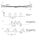
図7(a)〜(d)は、感光体ドラム2の表面移動速度と中間転写ベルト10上に転写した検知用パターン45のトナー濃度分布との関係を示す説明図である。
図7(a)は、感光体ドラム2と中間転写ベルト10との転写部の模式図である。感光体ドラム2と中間転写ベルト10との接触面において、感光体ドラム2と中間転写ベルト10とは互いに接触しながらも、トナーやベルト又は感光体表層の潤滑剤、潤滑層の影響でスリップしながら、それぞれ独立した速度Vo,Vbで移動している。図7(b)は、感光体ドラム2上に形成した検知用パターンにおいて、横軸に各パターンの間隔(距離)をとり、縦軸にトナー濃度をとったグラフである。本実施形態では、一定のトナー濃度で、パターン間隔PaNでパターン像が形成される。
7A to 7D are explanatory diagrams showing the relationship between the surface moving speed of the
FIG. 7A is a schematic diagram of a transfer portion between the
ここで、感光体ドラム2の表面移動速度Voが中間転写ベルト10の表面移動速度Vbに対して速い場合(Vo>Vb)、図7(b)に示した検知用パターンを中間転写ベルト10上に転写した後の検知用パターンは、図7(c)に示すようになる。この場合、転写部において感光体ドラム2の表面が中間転写ベルト10の表面を追い越すようになるため、中間転写ベルト10上におけるパターン間隔PaHは、感光体ドラム上におけるパターン間隔PaNよりも短くなる。また、図中Twで示したパターン濃度の広がり部分は、感光体ドラム2と中間転写ベルト10との速度差によるパターン崩れによる濃度分布を示している。これは、転写部において、感光体ドラム2と中間転写ベルト10とが高いトナー転写率を確保するために2mm近くのニップ部を有しているため、トナー像が両者にこすれるように転写し、速度差に応じて集積しているトナーが崩されるためである。
Here, when the surface moving speed Vo of the
一方、感光体ドラム2の表面移動速度Voが中間転写ベルト10の表面移動速度Vbに対して遅い場合(Vo<Vb)、図7(b)に示した検知用パターンを中間転写ベルト10上に転写した後の検知用パターンは、図7(d)に示すようになる。この場合、中間転写ベルト10上におけるパターン間隔PaLは、感光体ドラム2上におけるパターン間隔PaNよりも長くなる。また、図7(c)に示した場合と同様に、Twで示したパターン濃度の広がり部分も発生する。
On the other hand, when the surface moving speed Vo of the
本実施形態では、感光体ドラム2の表面移動速度変動により変動するパターン間隔PaH,PaLを高精度に検知することが望まれる。上述したように感光体ドラム2の表面移動速度変動により、中間転写ベルト10との速度差が周期的に変化し、検知用パターンの濃度分布の広がりも周期的に変化する。ここで、閾値を設定してパターン端部を認識する手法では、パターン崩れの影響で、端部でない部分を検知してしまうという問題や、パターン濃度が閾値を超えず認識できないという問題が発生する。そこで、本実施形態では、パターン濃度のピーク値をパターン検知タイミングとする。具体的には、CPU58は、既定のサンプリング周期で格納されたトナー濃度と相関の高いFIFO55の信号データ群からパターン濃度のピークを認識して、そのタイミング(データ番号)データをRAM60に格納する。これによって、より正確なパターン間隔PaH,PaLを認識することができる。
In the present embodiment, it is desired to detect the pattern intervals PaH and PaL, which fluctuate due to fluctuations in the surface movement speed of the
このようにして認識したパターン間隔の検知データ(以下、「パターン検知データ」という)は、RAM60に格納される。このパターン検知データは、感光体ドラム2の回転周期で変動したものとなる。本実施形態では、パターン検知データに含まれる他の周期成分を除去して、感光体ドラム2の変動成分(変動プロファイル)を抽出する。
The pattern interval detection data recognized in this manner (hereinafter referred to as “pattern detection data”) is stored in the
上述したパターン検知データは、形成されたパターン順に任意の基準タイミングから検知した時刻までの経過時間(tk01,tk02,tk03,・・・)に基づくデータである。よって、パターン検知データは、変動成分が重畳している単調増加のデータ群となる。そこで、このパターン検知データから増加傾向(傾き)分を除いてパターン変動データとする。増加傾向(傾き)分は、データ群から最小二乗法により求めることができ、倍率補正数値として扱われる。 The pattern detection data described above is data based on the elapsed time (tk01, tk02, tk03,...) From the arbitrary reference timing to the detected time in the order of the formed pattern. Therefore, the pattern detection data is a monotonically increasing data group in which the fluctuation components are superimposed. Therefore, pattern variation data is obtained by removing an increasing tendency (gradient) from the pattern detection data. The increasing tendency (gradient) can be obtained from the data group by the least square method, and is treated as a magnification correction numerical value.
また、感光体ドラム2の回転周期に対し、比較的高周波(10倍程度以上)の他の周期変動は、LPF(ローパスフィルタ)で除去する。本実施形態においては、感光体ドラム2の回転周期が動作モードで幅を持つものの数Hzであるため、カットオフ周波数が数十HzのLPFを設計している。これによって、モータ回転周期やギヤの噛合い周期変動等の高周波変動が除去され、感光体ドラム2等の低周波帯域の信号のみが抽出される。
Further, other periodic fluctuations having a relatively high frequency (about 10 times or more) with respect to the rotation period of the
このように検出された感光体ドラム一回転周期の変動プロファイルのデータを基に、CPU58は各感光体ドラム2の駆動制御補正値を算出し、制御目標値出力部38に送信する。この駆動制御補正値は、この変動成分に相当する感光体ドラムの表面移動速度変動を打消すように、各感光体ドラム2の回転角速度を個別に微調整する値である。つまり、図7に示したように、感光体ドラム2の表面移動速度が速くて平均より短いパターン間隔PaHが検出されたタイミングでは感光体ドラム2の駆動速度を遅くなるように補正し、感光体ドラムが遅くて長いパターン間隔PaLが検出されたタイミングでは感光体ドラム2の駆動速度を速くするように補正する。
The
ここで、上述したパターン変動データから算出された感光体ドラム一回転周期の変動プロファイルのデータは、感光体ドラムの露光ポイントSPにおける感光体ドラムの表面移動速度変動と、感光体ドラム2の表面上における転写位置である転写ポイントTPにおける感光体ドラムの表面移動速度変動の2つの影響が重畳して表れる中間転写ベルト10上のパターン間隔の変動に基づいて得られるものである。
Here, the fluctuation profile data of one rotation period of the photosensitive drum calculated from the pattern fluctuation data described above is the fluctuation of the surface movement speed of the photosensitive drum at the exposure point SP of the photosensitive drum, and the surface of the
そこで、図8に示すような、任意に設定された感光体ドラム2上の露光ポイントSPと転写ポイントTPとの間の位相差角度φを持つ構成において、感光体ドラム一回転周期をもつ感光体ドラムの表面移動速度変動を引き起こす感光体ドラム2の回転角速度変動と、中間転写ベルト10上のパターン間隔との関係を示し、上述したパターン検知データに基づくパターン変動データから、適切な駆動制御補正値を導出する手法について説明する。
Therefore, in a configuration having a phase difference angle φ between the exposure point SP and the transfer point TP on the
ドラムポジションセンサ20がマーキング4(図1参照)を検知したタイミングを基準に、一定時間間隔で感光体ドラム2上の露光ポイントSPに検知用パターンの潜像を書き込む。このとき、感光体ドラム回転角速度ωが下記の式(1)であったとする。
Based on the timing at which the drum position sensor 20 detects the marking 4 (see FIG. 1), a detection pattern latent image is written at the exposure points SP on the
![]()
![]()
上記式(1)において、右辺第2項のf(ω0t0+α)は、ドラムポジションセンサ20がマーキング4を検知したタイミングを基準に、任意の時間t0における感光体ドラム一回転周期と同じ周期をもつ回転角速度変動分を示している。具体的には、主として、感光体ドラム2の軸に設置されたドラム駆動ギヤ32の偏心等に起因する回転変動分を示している。αはドラムポジションセンサ20がマーキング4を検知したタイミングを基準とした周期変動の位相を示す。このときの感光体ドラム2の表面移動速度VSPは、感光体ドラムの半径をRとすると、下記の式(2)となる。
In the above formula (1), f (ω 0 t 0 + α) in the second term on the right side is the rotation period of the photosensitive drum at an arbitrary time t 0 with reference to the timing when the drum position sensor 20 detects the
![]()
![]()
また、露光ポイントSPで、一定間隔の微小時間δtにて形成される任意の2パターンのパターン間隔δP0は、下記の式(3)となる。
![]()
![]()
これらの検知用パターンは、感光体ドラム2が角度φだけ回転するのに要する時間Tφが経過した後に中間転写ベルト10上に転写される。ここでいう角度φは、図8に示すように、感光体ドラム回転中心と露光ポイントSPとを結ぶ仮想線と、感光体ドラム回転中心と転写ポイントTPとを結ぶ仮想線とのなす角である。
These detection patterns are transferred onto the
検知用パターンが中間転写ベルト10へ転写されるときの感光体ドラムの角速度ωφは、下記の式(4)となる。
![]()
![]()
式(4)の右辺第2項は、検知用パターンの転写時における感光体ドラム一回転周期の変動成分であるから、潜像書込時からTφ時間後を示す位相差はφとなる。このときの感光体ドラム2の表面移動速度VTRは、下記の式(5)となる。
Since the second term on the right side of the equation (4) is a fluctuation component of one rotation cycle of the photosensitive drum at the time of transfer of the detection pattern, the phase difference indicating the time Tφ after the latent image writing is φ. The surface moving speed VTR of the
![]()
![]()
また、中間転写ベルト10の表面移動速度は、感光体ドラム2の平均表面移動速度と一致しているとし、Vb=Rω0とすると、感光体ドラム2上のパターン間隔は、感光体ドラムの表面移動速度が中間転写ベルト10の表面移動速度よりも速いと短くなり、遅いと長くなる。したがって、中間転写ベルト10上に転写されたパターン間隔δPは、下記の式(6)となる。
Also, assuming that the surface moving speed of the

上記式(6)はスリップトランスファーを前提とした式である。しかし、転写条件によっては、タックトランスファーの傾向がある。スリップトランスファーとは、先述した図7で示したモデルのように感光体ドラムと転写ベルトが接触面において滑りながら、それぞれ独立した速度で移動しながらトナー像を転写することを言う。これによって、感光体ドラムの速度変動によってトナー像の転写位置が変動する。一方、タックトランスファーとは、感光体ドラムと転写ベルトが接触部分において滑ることなく密着して、両者同一の速度で移動しながらトナー像を転写することを言う。このとき、感光体ドラムの速度変動が発生しても転写ベルトの速度がそれに伴って移動するため転写位置は変動しない。したがって、スリップトランスファーとタックトランスファーの転写プロセスの違いでトナーパターン間隔は大きく異なる。 The above equation (6) is an equation based on slip transfer. However, there is a tendency for tack transfer depending on the transfer conditions. The slip transfer means that the toner image is transferred while moving at an independent speed while the photosensitive drum and the transfer belt slide on the contact surface as in the model shown in FIG. As a result, the transfer position of the toner image varies depending on the speed variation of the photosensitive drum. On the other hand, “tack transfer” means that the photosensitive drum and the transfer belt are in close contact with each other without slipping at the contact portion, and the toner image is transferred while moving at the same speed. At this time, even if the speed fluctuation of the photosensitive drum occurs, the transfer position does not change because the speed of the transfer belt moves accordingly. Therefore, the toner pattern interval varies greatly depending on the transfer process between slip transfer and tack transfer.
そこで、式(6)に転写係数κを導入する。κ=1のとき、トナー像の転写プロセスはスリップトランスファーとなっている。一方、κ=0のとき、トナー像の転写プロセスはタックトランスファーとなっている。実際には、転写プロセスはスリップトランスファーとタックトランスファーが共存するような状態で、転写条件(転写電圧)による感光体ドラムと転写ベルトの密着度やトナー特性や潤滑剤の量で変化する。よって、κは0から1の値をとる。式(6)は以下のようになる。 Therefore, the transfer coefficient κ is introduced into Equation (6). When κ = 1, the toner image transfer process is slip transfer. On the other hand, when κ = 0, the toner image transfer process is tack transfer. Actually, the transfer process changes depending on the degree of adhesion between the photosensitive drum and the transfer belt, the toner characteristics, and the amount of lubricant depending on the transfer conditions (transfer voltage) in a state where slip transfer and tack transfer coexist. Therefore, κ takes a value from 0 to 1. Equation (6) is as follows.
ここで、変動成分fは、平均角速度ω0に対して十分小さいことから、上記式(7)は下記の式(8)に近似することができる。
検知用パターンの潜像形成タイミングが実際の一定時間間隔である場合、露光ポイントSPにて微小時間δtでない一定時間間隔Teにてパターン書込みを行い、転写後に中間転写ベルトに対向する受光素子42で検知用パターンの通過タイミングを検知して、中間転写ベルト10上のパターン検知タイミングを認識する。ここまで、ドラムポジションセンサ20がマーキング4を検知したタイミングを基準としている。そのタイミングに書き込まれた検知用パターンが受光素子42で検知される位置を基準(0)として、時間TeN(N:自然数)に書き込まれたN番目のパターンまでの間隔PNは、下記の式(9)となる。
When the detection pattern latent image formation timing is an actual constant time interval, pattern writing is performed at the exposure point SP at a constant time interval Te that is not a minute time δt, and after the transfer, the
この式(9)から下記の式(10)が得られる。
![]()
![]()
このように、一定時間間隔Teにて書き込まれたパターン群は、中間転写ベルト上にて、式(10)にて示されるパターン間隔となり、受光素子で検知される。上述したRAM60に格納されるパターン検知データ(時間データ)は、中間転写ベルト10の表面移動速度情報から中間転写ベルト上の位置情報に換算される。式(10)中の右辺第1項は、パターン検知データの傾きに相当し、倍率誤差の検出に用いられる。パターン変動データは、上述したフィルタ処理を用いて感光体ドラム一回転周期で発生する変動成分(変動プロファイル)が算出される。この変動成分は、式(10)中の右辺第2項と第3項に相当する。なお、式(10)中の右辺第4項である積分定数Cは、定常偏差であり、フィルタ処理によって算出される変動成分には影響しない。
As described above, the pattern group written at the constant time interval Te becomes the pattern interval represented by the expression (10) on the intermediate transfer belt, and is detected by the light receiving element. The pattern detection data (time data) stored in the
ここで、フィルタ処理でパターン検知データの傾き成分と、定常偏差分を除去して得られた感光体ドラム一回転周期の変動成分は式(11)となる。これは、上述した式(1)中の第2項で示される感光体ドラム2の回転角速度変動に起因するものである。しかし、得られた変動成分は、感光体ベルト上書込み時の回転角速度変動分((11)式第1項)と転写ベルトへの転写時の回転角速度変動分((11)式第2項)が重畳された結果である。
Here, the inclination component of the pattern detection data and the fluctuation component of the rotation cycle of the photosensitive drum obtained by removing the steady-state deviation by the filter processing are expressed by Expression (11). This is due to the fluctuation of the rotational angular velocity of the
![]()
![]()
よって、この感光体ドラムの回転角速度変動を補正する駆動制御補正数値としては、まず、フィルタ処理後の式(11)の感光体ドラム一回転周期の変動成分を算出する。次に、その変動成分から式(11)の第1項または、第2項のみを抽出する。抽出した関数Fは感光体ドラム1回転の回転角変動を示すので、その変動分を打消すように反転した数値を算出する。この駆動制御補正数値としては、回転角変動を示す関数Fを利用するか、またはそれを微分して、回転角速度変動を示す関数fのどちらを利用してもよい。 Therefore, as the drive control correction value for correcting the rotational angular velocity fluctuation of the photosensitive drum, first, the fluctuation component of the photosensitive drum one rotation cycle of the expression (11) after the filter processing is calculated. Next, only the first term or the second term of Expression (11) is extracted from the fluctuation component. Since the extracted function F indicates the rotation angle fluctuation of one rotation of the photosensitive drum, the inverted value is calculated so as to cancel the fluctuation. As this drive control correction numerical value, either the function F indicating the rotation angle fluctuation or the function f indicating the rotation angular speed fluctuation by differentiating it may be used.
次に、式(11)のフィルタ処理後の変動成分から、第1項または、第2項のみを抽出する手法、つまり、2つの感光体ドラム一回転周期の任意周期関数Fが重畳されたデータから、関数Fを算出する手法を説明する。説明の便宜上、式(11)を式(12)に置き換える。ここで、R=1、ω0t0+α=xとする。また、図1に示した位相差角度φの反対の角度をφ’として第2項をφ’の位相遅れとして表す。 Next, a method of extracting only the first term or the second term from the fluctuation component after the filter processing of the expression (11), that is, data in which an arbitrary periodic function F of one rotation period of two photosensitive drums is superimposed. A method for calculating the function F will be described. For convenience of explanation, equation (11) is replaced with equation (12). Here, it is assumed that R = 1 and ω 0 t 0 + α = x. Further, the angle opposite to the phase difference angle φ shown in FIG. 1 is expressed as φ ′, and the second term is expressed as the phase delay of φ ′.
![]()
![]()
式(12)のフィルタ処理後の変動成分は、感光体ドラム一回転分、または複数回転分のデータ列である。ここで、この変動成分データ列を用いて、位相差角度φ’、2φ’、3φ’・・・(n−1)φ’分の位相を遅らせた同じ変動成分を用いて以下の式(13)のようにn個のデータ列を作成する。個数nは任意で、多い方がよい。また、最適値に関しては後で説明する。 The fluctuation component after the filter processing of Expression (12) is a data string for one rotation of the photosensitive drum or a plurality of rotations. Here, using this variation component data string, the following equation (13) using the same variation component in which the phase difference angle φ ′, 2φ ′, 3φ ′... (N−1) φ ′ is delayed. N data strings are created as shown in FIG. The number n is arbitrary and is preferably large. The optimum value will be described later.
式(13)の[1]はフィルタ処理後の変動成分である。[2]は元の変動成分に位相差角度φだけ位相を遅らせた同じ変動成分を加算している。[3]は[2]のデータに、元の変動成分を2φ’だけ位相を遅らせたデータを加算している。[n]は、[n−1]のデータに、元の変動成分を(n−1)φ’だけ位相を遅らせたデータを加算している。このようにn個のデータ列を作成している。これらn個のデータ列を計算すると式(14)となる。 [1] in Expression (13) is a fluctuation component after the filter processing. In [2], the same fluctuation component whose phase is delayed by the phase difference angle φ is added to the original fluctuation component. [3] adds data obtained by delaying the phase of the original fluctuation component by 2φ ′ to the data of [2]. [N] is obtained by adding data obtained by delaying the phase of the original fluctuation component by (n−1) φ ′ to the data of [n−1]. In this way, n data strings are created. When these n data strings are calculated, equation (14) is obtained.
これらn個のデータ列の和Sumを求めると式(15)となる。
![]()
![]()
ここで、式(15)の第1項の関数F(x)はn倍されているのに対し、他項の関数F(x)は位相が異なり分散されている。また、0から1の値をとる転写係数κが係数となっていることがわかる。よって、第1項の関数F(x)が他項と相対的に大きいことから、式(15)の和Sumをnで除算することで、関数F(x)が導出される。 Here, the function F (x) of the first term in the equation (15) is multiplied by n, whereas the function F (x) of the other term has a different phase and is dispersed. It can also be seen that the transfer coefficient κ taking a value from 0 to 1 is a coefficient. Therefore, since the function F (x) of the first term is relatively larger than the other terms, the function F (x) is derived by dividing the sum Sum of Expression (15) by n.
![]()
![]()
図9に上記演算処理をブロック線図で示す。図9(a)が上記演算処理ブロックである。図9(b)は、FIFOとゲインで構成される図9(a)のブロック121の内部処理を示している(以下、FIFOシステムという)。
FIG. 9 is a block diagram showing the arithmetic processing. FIG. 9A shows the arithmetic processing block. FIG. 9B shows the internal processing of the
FIFOシステムは、入力データ127に対し転写係数κとの積を求める(図9(b)129)。次に、図9(b)130で感光体ドラムの回転角度φ’分の位相遅れが与えられる。実際には、位相遅れに相当する時間だけ過去の入力データを出力する。入力データは離散データであるためz変換を表す演算子記号Zで示す。入力データは、先述のように時間TeN(N:自然数)に書き込まれたN番目のパターンの間隔PNに関するデータである。ブロック130は、角度φ’分のFIFOメモリである。つまり、回転中心角度φ’内で感光体ドラム表面上に形成されたトナーパターン数φ’d分のデータを記憶するメモリである。入力されたデータを記憶し、φ’d分過去のデータを出力する(図9(b)128)。
The FIFO system obtains the product of the transfer coefficient κ for the input data 127 (FIG. 9B) 129. Next, in FIG. 9B, a phase delay corresponding to the rotation angle φ ′ of the photosensitive drum is given. Actually, past input data is output for a time corresponding to the phase delay. Since the input data is discrete data, it is indicated by an operator symbol Z representing z conversion. The input data is data relating to the interval PN of the Nth pattern written at time TeN (N: natural number) as described above.
図9(a)の入力データ120は、式(12)で表されるフィルタ処理後の変動成分である。この入力データは、FIFOシステム121と加算器123及び加算器124へ送られる。FIFOシステム121では先に説明した遅延処理が行われ、加算器123にて、遅延処理後の入力データと元の入力データが加算される。加算器123の演算は、式(13)の[2]の演算に相当し、その結果132は、式(14)の[2]と等しい。FIFOシステム121と加算器123を含む図中破線枠で示すシステムがn−1個並列接続されており、各システムで計算された結果が加算器124へ送られる。ちなみに、加算結果133は式(14)の[3]となり、加算結果134は式(14)の[n]と等しい。加算器124では、式(15)の加算演算が行われ、ゲイン125では1/nとの積を求める式(16)に示す演算が行われる。この演算結果126は、先述したように関数f(x)である。
The
FIFOシステムにて位相角度φ’分ずつ位相遅延して作成されるデータ列の個数nについて説明する。式(16)では、導出したいF(x)成分は同位相で加算されるのに対し、除去したいF(x)以外の項(F(x−φ’)など)は位相が異なり分散されることを利用してF(x)を導出している。そのため、F(x)以外の項は感光体ドラム1回転(2π)内に均等分散することが望ましい。つまり、F(x)以外の項の位相差、−φ’、−2φ’、・・・、nφ’が感光体ドラム一回転(2π)において均等に配置されるように設定する。よって、式(17)が成立するnを導出して設定するのが望ましい。 A description will be given of the number n of data strings created by delaying the phase by the phase angle φ ′ in the FIFO system. In Equation (16), the F (x) component to be derived is added in the same phase, while terms other than F (x) to be removed (F (x−φ ′), etc.) have different phases and are dispersed. This is used to derive F (x). Therefore, it is desirable that the terms other than F (x) are evenly distributed within one rotation (2π) of the photosensitive drum. That is, the phase differences other than F (x), −φ ′, −2φ ′,..., Nφ ′ are set so as to be evenly arranged in one rotation (2π) of the photosensitive drum. Therefore, it is desirable to derive and set n for which Expression (17) holds.
![]()
![]()
ただし、mは自然数である。例えば、図1に示した位相差角度がφ’が216°(φ’=3.77rad)であったとき、式(17)はn=10、m=6で成立する。図9(a)では9個の破線枠システムが並列接続された演算処理が行われる。その結果、均等分散の効果でF(x)の導出精度は向上する。 However, m is a natural number. For example, when the phase difference angle shown in FIG. 1 is φ ′ is 216 ° (φ ′ = 3.77 rad), Equation (17) is established when n = 10 and m = 6. In FIG. 9A, arithmetic processing is performed in which nine broken line frame systems are connected in parallel. As a result, the accuracy of deriving F (x) is improved by the effect of uniform dispersion.
上記例のようにn=10で、図9(a)において9個の破線枠システムが並列接続した場合、9個目のFIFOシステムからデータが出力するための合計の遅延処理は9φ’となる。データ入力120から9φ’分より多くのデータが入力されると、最後に接続されたFIFOシステムから数値が出力される。そして、加算器124、ゲイン125の処理を行った後、出力データ126が得られる。この出力データを少なくとも感光体ドラム一回転分以上算出することで、感光体ドラム回転角変動F(x)が得られる。したがって、データ入力120は、少なくとも感光体ドラム回転角9φ’+2π分のデータを送る必要がある。データ入力120には、感光体ドラム一回転または整数回転分の検知パターン数の変動データ列が保持されている。この変動データ数は、先の遅延処理の合計と感光体ドラム一回転の和に相当するデータ数よりも少ない。そこで、データ入力120は、保持されている変動データを繰返し送るように設定されている。変動データを繰返し送信することで、感光体ドラム回転角9φ’+2π分のデータを入力する。出力データ126が9φ’分のデータ処理後、感光体ドラム一回転分のデータ数に到達すると感光体ドラム回転角変動F(x)とする。また、データ入力120に感光体複数回転分の変動データが保持されている場合は、出力データ126が、その感光体ドラム回転数分のデータ数に到達すると、感光体ドラム複数回転分のデータを同期加算して感光体ドラム一回転分の回転角変動F(x)とする。
When n = 10 and nine broken line frame systems in FIG. 9A are connected in parallel as in the above example, the total delay processing for outputting data from the ninth FIFO system is 9φ ′. . When more data than 9φ 'is input from the
検知パターンは時間Te間隔で形成され、その検知データが得られる。この時間的に離散したデータに対し先述した図9に示す演算処理が行われるが、FIFOシステムから遅延処理され出力するタイミングと検知データが入力されるタイミングが一致して加算器123で処理されると、時間的離散化による誤差の影響が少ない。よって、回転角度φ’分の位相角において検知パターンが等間隔であることが望ましい。また、この演算処理で最終的に得られた感光体ドラム複数回転分のデータを同期加算平均する場合においては、感光体ドラム一周長において検知パターンが等間隔であれば、離散化による誤差が無く、平均値が導出できる。よって、検知タイミングは、回転角度φ’分の位相角、感光体ドラム一周(2π)において等間隔であることが望ましい。
The detection pattern is formed at time Te intervals, and the detection data is obtained. The above-described arithmetic processing shown in FIG. 9 is performed on the temporally discrete data. The timing at which the delay processing is performed from the FIFO system and the timing at which the detection data is input are matched to be processed by the
ここまでは、ドラムポジションセンサ20がマーキング4を検知したタイミングを基準として検知用パターンを書込み、その後、この検知用パターンが中間転写ベルト10に転写された後に受光素子42で検知される位置を基準として、その検知用パターンの通過タイミングを検知した。しかし、中間転写ベルト10の表面移動速度が不安定であったり、温度変化による駆動ローラ径の膨張、収縮等が原因で平均表面移動速度が不確定であったりする場合、パターン検知基準の認識に誤差が生じてしまう。そこで、別途、基準となるホームトナーマークを検知パターン群とは別に形成するとよい。このホームトナーマークを基準に中間転写ベルト10上の検知用パターンの通過タイミングを検知する。この場合、ホームトナーマークの書込みタイミングと、ドラムポジションセンサ20がマーキング4を検知したタイミングとの位相関係を認識しておき、駆動制御補正時の位相値に反映させる必要がある。
Up to this point, the detection pattern is written based on the timing at which the drum position sensor 20 detects the
本実施形態によれば、感光体ドラム2上の露光ポイントSPと転写ポイントTPとの位置関係(露光ポイントSPと転写ポイントTPとの位相差回転角φ)がどのような関係であっても、中間転写ベルト10上にて検出されたパターン検知データから、感光体ドラム2の表面移動速度変動を補正する駆動制御補正値を高精度に求めることができる。
According to the present embodiment, regardless of the positional relationship between the exposure point SP on the
なお、上記特許文献1に記載された従来技術のように、露光ポイントSPと転写ポイントTPとの位相差角度を実際のφ’とは異なる180°に設定して駆動制御補正数値を算出して制御する場合の誤差は、式(16)にそれぞれφ’と180°とを代入して得られるパターン変動値の差分から求めることができる。具体例として、感光体ドラム半径Rを20mmとし、回転角速度の変動を変動率(Δω/ωo)0.1%の振幅を持つベルト一回転周期の正弦波状とし、αを0とした場合、位相差角度φとして2.53rad(145°)と3.14rad(180°)とを代入したときのグラフは、図10に示すとおりである。このグラフには、これらの差分(ERROR)も示してある。このように、露光ポイントSPと転写ポイントTPとの位相差角度が35°だけ異なる場合、回転角速度の変動率が0.1%という小さいものであっても最大で約12μmのパターン変動量の差が発生することがわかる。この差が従来技術の手法を用いた場合の制御補正誤差となる。本実施形態によれば、このような誤差が発生することがなく、高精度に制御補正することができる。
As in the prior art described in
また、ここまでは、感光体ドラム一回転周期をもつ感光体ドラムの回転角速度変動成分に起因する感光体ドラム表面移動速度変動に関して説明したが、その他の原因に起因する感光体ドラムの表面移動速度変動に対しても、同様に駆動制御補正数値を求めることができる。例えば、駆動モータ軸プーリと感光体ドラム軸プーリとの間にタイミングベルトが張架された駆動伝達機構の場合、そのタイミングベルトの回転周期ωtbと、露光ポイントSPと転写ポイントTPとの位相差角度φをタイミングベルトの回転周期に換算したφtbとを代入して上述と同様の処理をすればよい。この場合、タイミングベルト上にマーキングとドラムポジションセンサが必要であるが、感光体ドラム軸プーリとタイミングベルトとの間にすべりが無ければ、ドラム軸プーリに設置されたマーキングの検知タイミングからタイミングベルトの回転の基準タイミングを設定してもよい。 Up to this point, the photosensitive drum surface moving speed fluctuation caused by the rotational angular speed fluctuation component of the photosensitive drum having one rotation period of the photosensitive drum has been described. However, the photosensitive drum surface moving speed caused by other causes is described. Similarly, the drive control correction numerical value can be obtained for the fluctuation. For example, in the case of a drive transmission mechanism in which a timing belt is stretched between a drive motor shaft pulley and a photosensitive drum shaft pulley, the rotation period ωtb of the timing belt and the phase difference angle between the exposure point SP and the transfer point TP The same processing as described above may be performed by substituting φtb obtained by converting φ into the rotation period of the timing belt. In this case, a marking and a drum position sensor are required on the timing belt, but if there is no slip between the photosensitive drum shaft pulley and the timing belt, the timing belt is detected from the detection timing of the marking installed on the drum shaft pulley. A reference timing for rotation may be set.
次に、作像ユニット(画像形成ユニット)の構成が異なる一変形例(以下、本変形例を「変形例1」という)について図11を参照して説明する。
近年では、作像ユニットの高耐久化と小型化の両立が求められている。本変形例1の画像形成装置では、感光体ドラム85を従来よりも大口径とし、感光体ドラムの感光層の高耐久化を実現している。また、感光体ドラム85の周囲に配置されるクリーニング部81、電荷チャージ部82、ラインLED露光部83、現像部84を感光体ドラム85に対して図中左側(感光体ドラム85の一方側で感光体ドラム85に接触し且つ中間転写ベルト86の移動方向に直交する仮想平面VPよりも他方側)に配置することで、画像形成ユニット間隔LSTを短くしている。これによって、画像形成装置の横方向(図中左右方向)の寸法が小さくなる。このような画像形成装置では、露光ポイントSPから転写ポイントTPまでの位相差角度φ1が180°から大きくズレた角度になる。本変形例1ではφ1は120°である。このような画像形成装置においても、上述した実施形態と同様の補正動作を行うことで、高精度な駆動制御補正数値を求めることができる。
Next, a modified example (hereinafter referred to as “modified example 1”) having a different configuration of the image forming unit (image forming unit) will be described with reference to FIG.
In recent years, it has been required to achieve both high durability and downsizing of an image forming unit. In the image forming apparatus according to the first modification, the
なお、図11では、中間転写ベルト86上に並ぶ2つの作像ユニット80,80を図示しているが、図1の構成と同様、4つの作像ユニットを並設してフルカラー画像の形成が可能である。また、3つの作像ユニットを用いてフルカラー画像を形成する構成も可能である。また、図11では、中間転写ベルト86の上側に作像ユニット80を配置しているが、図1の構成と同様に、中間転写ベルト86の下側に作像ユニット80を配置する構成も可能である。
In FIG. 11, two
次に、黒色(ブラック)用の作像ユニットを他の作像ユニットよりも大口径とした他の変形例(以下、本変形例を「変形例2」という)について図12を参照して説明する。 Next, another modified example in which the black image forming unit has a larger diameter than the other image forming units (hereinafter referred to as “modified example 2”) will be described with reference to FIG. To do.
本変形例2においては、中間転写ベルト96上に並列配置された複数の画像形成ユニット間で、露光ポイントSPと転写ポイントTPとの位相差角度が互いに異なっている。一般に、カラー画像形成装置の全画像出力において、モノクロ画像出力の占める割合は、カラー画像に対して高い場合が多い。本変形例2の画像形成装置では、使用頻度の高いブラック作像ユニット90Kの感光体ドラム92を他色の作像ユニット90の感光体ドラム91に対して大口径とすることで、高耐久化を実現している。本変形例2においても、上記変形例1の場合と同様に、大口径である黒の感光体ドラム92についてはその周辺装置を感光体ドラム92に対して図中左側に配置し、小型化を実現している。また、感光層部の材料の共通化に伴い、感光層内の電荷移動現象、トナーの転写現象を同様にするため、露光、現像、転写部間距離を他の画像形成ユニットと一致させるため、黒の感光体ドラム92における露光ポイントSPと転写ポイントTPとの位相差角度φ3は、他色の位相差角度φ2とは異なるように設定されている。上述した実施形態における補正動作は、個々の画像形成ユニットごとに個別に行うことができるので、このような画像形成装置においても、上述した実施形態と同様の補正動作を行うことで、高精度な駆動制御補正数値を求めることができる。
In the second modification, the phase difference angle between the exposure point SP and the transfer point TP is different between the plurality of image forming units arranged in parallel on the
なお、図12では、他色の作像ユニット90を一つのみ図示しているが、図1の構成と同様、3つの作像ユニット90とブラック作像ユニット90Kで合計4つの作像ユニットを並設してフルカラー画像の形成が可能である。また、2つの他色の作像ユニット90とブラック作像ユニット90Kで合計3つの作像ユニットを用いてフルカラー画像を形成する構成も可能である。また、図12では、中間転写ベルト96の上側に作像ユニット90,90Kを配置しているが、図1の構成と同様に、中間転写ベルト96の下側に作像ユニットを配置する構成も可能である。
In FIG. 12, only one
次に、潜像担持体としてベルト状感光体を用いた更に他の変形例(以下、本変形例を「変形例3」という)について図13を参照して説明する。
上記実施形態や上記変形例1及び2では、潜像担持体がドラム形状の感光体である場合を例示して説明したが、本発明は、潜像担持体が露光ポイントSPと転写ポイントTPとをもつ表面移動部材であれば適用可能である。よって、例えば、本変形例3のように、無端状ベルト形状の感光体であっても適用できる。
Next, still another modified example (hereinafter, this modified example will be referred to as “modified example 3”) using a belt-like photoconductor as a latent image carrier will be described with reference to FIG.
In the above-described embodiment and
本変形例3における感光体ベルト103は、3つの支持ローラに張架され、そのうちの1つである駆動ローラによって、中間転写ベルト105と同一方向で無端走行されるようになっている。また、感光体ベルト103は最も下方に位置したローラ部分で中間転写ベルト105に接触している。感光体ベルト103の周囲には、感光体ベルト103を所定の電位に帯電させる帯電チャージャ102、帯電されたベルト表面を画像信号に基づき書込み光101で露光して静電潜像を形成する図示しない露光装置、静電潜像に帯電したトナーを供給して現像する現像装置100、及び、トナー像を中間転写ベルト105上に転写する転写ローラ104が順に配設されている。なお、転写ローラ104は、中間転写ベルト105の内側に配置され、感光体ベルト103の最下端のローラに対向した位置に設けられている。また、中間転写ベルト105上に形成された検知用パターンはパターンセンサ106にて検知用パターンの通過が検知される。このような感光体ベルト103においては、駆動ローラの偏心や感光体ベルト103の厚み偏差分布により感光体ベルト103の表面移動速度変動が発生する。ここでも同様に感光体ベルト一回転周期の表面移動速度変動を補正したい場合には、感光体ベルト103の回転角速度ωobと感光体ベルト一回転周期に対する書込み光101の露光ポイントSPと中間転写ベルト105が接している転写ポイントTPとの位相差回転角φobとから、駆動制御補正値を求めることができる。ちなみに、上述した感光体ドラムの半径R及び回転角速度ωに相当するパラメータは、感光体ベルト103の周長と表面移動速度とから設定することができる。
The
以上のように、本実施形態(上述した各変形例を含む。)では、露光ポイントSPから転写ポイントTPまでの位相差角度φがどのような角度であっても、高精度な駆動制御補正数値を求めることができる。したがって、位相差角度φを180°から大きく外れた角度となるように感光体ドラム回りのレイアウトを決めることができる。この効果は、次の点で大きなメリットである。 As described above, in the present embodiment (including the above-described modifications), a highly accurate drive control correction value is used regardless of the phase difference angle φ from the exposure point SP to the transfer point TP. Can be requested. Therefore, the layout around the photosensitive drum can be determined so that the phase difference angle φ is an angle greatly deviated from 180 °. This effect is a great merit in the following points.
すなわち、上記特許文献1に記載の画像形成装置のように位相差角度φが180°である構成は、環境、経時による部品変化やパターン検知誤差などを含めて、発生する感光体ドラム表面移動速度変動に対して最も位置ズレが発生しやすい構成である。例えば、感光体ドラム上の露光ポイントSPにおける感光体ドラム一回転周期の回転角速度変動が最大であった場合、その付近に形成される検知用パターンのパターン間隔は理想間隔よりも広がる。そして、この検知用パターンが転写ポイントTPに到達する時には、位相差角度φが180°であることから、感光体ドラムの回転角速度変動は最小となる。よって、中間転写ベルト10の表面移動速度に対して感光体ドラム2の表面移動速度が最も遅い状態で転写が行われることになり、中間転写ベルト10上における当該パターン間隔は、理想よりもさらに広がることになる。これに対し、位相差角度φが180°から離れるほど位置ズレが小さくなる。よって、本実施形態によれば、位相差角度φを180°から大きく外れた角度となるように構成できることにより、位相差角度φが180°である場合に比べてそもそもの位置ズレ量が少なくできるというメリットがある。
That is, the configuration in which the phase difference angle φ is 180 ° as in the image forming apparatus described in
また、他のメリットしては、次のようなメリットが挙げられる。
図1に示した画像形成装置を例に挙げて説明すると、この画像形成装置では、装置下部(露光装置15の下方)に積層したシートを最短経路で装置上部に排出するシート搬送経路中に二次転写部を設けることにより小型化やプリント速度の高速化を実現している。このレイアウトの場合、上述したように、露光装置15を各作像ユニット1の下方に設置する必要があるが、位相差角度が180°であると出射レンズに飛散トナーが堆積し、適正な潜像形成を行うことができないおそれがある。これに対し、図1に示した本実施形態の画像形成装置では、位相差角度φが145°であるため、出射レンズのレンズ面が水平方向に対して傾斜する。よって、出射レンズに飛散トナーが堆積しにくくなり、適正な潜像形成を安定して維持できるというメリットがある。この他にも、上述した各変形例で説明したメリットもある。
As other merits, there are the following merits.
The image forming apparatus shown in FIG. 1 will be described as an example. In this image forming apparatus, sheets stacked on the lower part of the apparatus (below the exposure apparatus 15) are discharged into the sheet conveying path for discharging the sheet to the upper part of the apparatus by the shortest path. By providing the next transfer section, it is possible to reduce the size and increase the printing speed. In the case of this layout, as described above, it is necessary to install the
以上、本発明を図示例により説明したが、本発明はこれに限定されるものではない。例えば、図示例の中間転写方式のタンデム型画像形成装置に限らず、直接転写方式のタンデム型画像形成装置にも本発明を適用可能である。直接転写方式の場合、記録材は転写ベルト等の搬送部材(表面移動部材)により搬送され、検知用パターンは上記搬送部材(表面移動部材)の表面に転写させたものを、パターン検知手段で検知してやればよい。なお、タンデム型画像形成装置においては、各色作像ユニットの配置順などは任意である。また、感光体ドラム等の潜像担持体を1つのみ備えるモノクロ画像形成装置にも本発明は適用可能である。さらに、画像形成装置においては、現像装置や露光装置等の各機器も適宜な構成のものを採用可能である。もちろん、画像形成装置としてはプリンタに限らず、複写機やファクシミリ、あるいは複数の機能を備える複合機であっても良い。 As mentioned above, although this invention was demonstrated by the example of illustration, this invention is not limited to this. For example, the present invention can be applied not only to the intermediate transfer type tandem image forming apparatus of the illustrated example but also to the direct transfer type tandem image forming apparatus. In the case of the direct transfer method, the recording material is conveyed by a conveying member (surface moving member) such as a transfer belt, and the detection pattern is detected by the pattern detecting means transferred to the surface of the conveying member (surface moving member). Just do it. In the tandem type image forming apparatus, the arrangement order of the color image forming units is arbitrary. The present invention is also applicable to a monochrome image forming apparatus having only one latent image carrier such as a photosensitive drum. Further, in the image forming apparatus, it is possible to adopt an appropriate configuration for each device such as a developing device and an exposure device. Of course, the image forming apparatus is not limited to a printer, and may be a copier, a facsimile machine, or a multifunction machine having a plurality of functions.
1(Y,C,M,K) 作像ユニット
2,85,91,92 感光体ドラム(潜像担持体)
4 マーキング
10,105 中間転写ベルト(表面移動部材)
13 二次転写ローラ
15 露光装置
20 ドラムポジションセンサ
32 ドラム駆動ギヤ
33 駆動モータ
35 ロータリーエンコーダ
37 コントローラ
38 制御目標値出力部
40 パターンセンサ
44 転写位置調整用パターン
45 検知用パターン
103 感光体ベルト(潜像担持体)
SP 露光ポイント
TP 可視像転写ポイント
1 (Y, C, M, K)
4 Marking 10, 105 Intermediate transfer belt (surface moving member)
DESCRIPTION OF
SP Exposure point TP Visible image transfer point
Claims (11)
前記潜像担持体の回転角速度が目標回転角変位又は角速度と一致するように前記潜像担持体の駆動制御を行う駆動制御手段と、
前記潜像担持体から前記表面移動部材に転写させた、前記表面移動部材の表面移動方向に沿って配列される複数の検知用パターンを検知するパターン検知手段と、
該パターン検知手段が検知した検知データから前記潜像担持体の周期的な表面移動速度変動を示すパターン間隔変動成分を抽出した後、この抽出した変動成分を、前記潜像担持体の回転軸に直交する仮想平面上で潜像担持体表面における潜像書込位置及び可視像転写位置と潜像担持体の回転中心とをそれぞれ結んで得られる2つの仮想線のなす角度(ただし、潜像書込位置を基準点とする前記潜像担持体回転方向と反対方向の角度)を示す前記変動成分の位相差に基づいて補正することにより、前記潜像担持体1周期の回転角変動量又は回転角速度変動を認識し、該回転角変動量又は回転角速度変動を打消す反転値を補正値とし、該補正値を補正前の上記目標回転角変位又は角速度に重畳させることにより前記駆動制御手段が用いる目標回転角変位又は角速度を補正する補正手段と
を有し、
前記補正手段は、前記抽出した変動成分に対し、該変動成分の位相差と前記潜像担持体と前記表面移動部材との転写状態に基づく処理をN−1回繰返し行い、各回の処理で得られた変動成分の平均値を前記潜像担持体1周期の回転角変動量又は回転角速度変動とし、
該変動成分の位相差のN倍が前記潜像担時体1回転の整数倍であることを特徴とする画像形成装置。 After forming a latent image on the latent image carrier, the visible image obtained by visualizing the latent image is directly on a recording material conveyed by a conveying member as a surface moving member or an intermediate transfer member as a surface moving member In an image forming apparatus for transferring to a recording material via
Drive control means for performing drive control of the latent image carrier so that the rotational angular velocity of the latent image carrier matches a target rotational angular displacement or angular velocity;
Pattern detecting means for detecting a plurality of detection patterns arranged along the surface moving direction of the surface moving member transferred from the latent image carrier to the surface moving member;
After extracting a pattern interval fluctuation component indicating a periodic surface movement speed fluctuation of the latent image carrier from the detection data detected by the pattern detection means, the extracted fluctuation component is applied to the rotation axis of the latent image carrier. An angle formed by two virtual lines obtained by connecting the latent image writing position and visible image transfer position on the surface of the latent image carrier and the rotation center of the latent image carrier on the orthogonal virtual plane (however, the latent image By correcting based on the phase difference of the fluctuation component indicating an angle in the direction opposite to the rotation direction of the latent image carrier with respect to the writing position, the rotation angle fluctuation amount of one cycle of the latent image carrier or The drive control means recognizes the rotation angular velocity fluctuation, sets the rotation angle fluctuation amount or the inverted value that cancels the rotation angular speed fluctuation as a correction value, and superimposes the correction value on the target rotation angular displacement or angular velocity before correction. Target rotation used Displacement or and a correcting means for correcting the angular velocity,
The correction means repeatedly performs the process based on the phase difference of the fluctuation component and the transfer state of the latent image carrier and the surface moving member on the extracted fluctuation component N-1 times, and is obtained in each process. The average value of the obtained fluctuation components is defined as the rotation angle fluctuation amount or rotation angular velocity fluctuation of one cycle of the latent image carrier,
An image forming apparatus, wherein N times the phase difference of the fluctuation component is an integral multiple of one rotation of the latent image carrier.
前記複数の支持回転体のうちの少なくとも1つの回転情報に基づき、前記表面移動部材が等速で表面移動するように前記駆動支持回転体の駆動を制御する表面移動部材駆動制御手段を有することを特徴とする、請求項1〜5のいずれか1項に記載の画像形成装置。 The surface moving member is composed of an endless belt that is stretched over a plurality of support rotating bodies including a driving support rotating body,
Surface moving member drive control means for controlling the driving of the driving support rotating body so that the surface moving member moves on the surface at a constant speed based on rotation information of at least one of the plurality of supporting rotating bodies. The image forming apparatus according to claim 1, wherein the image forming apparatus is characterized.
前記補正手段は、前記潜像担持体の回転角速度平均値ω0及び回転半径Rとして、無端状ベルトで構成された当該潜像担持体のベルト周長及び当該潜像担持体の平均表面移動速度を用いて当該潜像担持体を円柱形状のものに換算したときの回転角速度平均値及び回転半径を用いることを特徴とする、請求項1〜6のいずれか1項に記載の画像形成装置。 The latent image carrier is composed of an endless belt that is stretched over a plurality of support rotators including a drive support rotator,
The correction means uses, as the rotation angular velocity average value ω0 and the rotation radius R of the latent image carrier, the belt circumferential length of the latent image carrier constituted by an endless belt and the average surface moving speed of the latent image carrier. The image forming apparatus according to any one of claims 1 to 6, wherein a rotation angular velocity average value and a rotation radius when the latent image carrier is converted into a cylindrical shape are used.
個々の前記潜像担持体において可視像を形成するための各部品は、前記潜像担持体の一方側で潜像担持体表面に接触し且つ前記表面移動部材の表面移動方向に直交する仮想平面よりも他方側に位置するよう、配置されていることを特徴とする、請求項1〜8のいずれか1項に記載の画像形成装置。 A plurality of the latent image carriers are provided along the surface moving direction of the surface moving member,
Each component for forming a visible image on each of the latent image carriers is in contact with the surface of the latent image carrier on one side of the latent image carrier and is orthogonal to the surface movement direction of the surface moving member. The image forming apparatus according to claim 1, wherein the image forming apparatus is disposed so as to be located on the other side of the plane.
該複数の潜像担持体のうちの少なくとも1つの潜像担持体は、その周長が他の潜像担持体の周長と異なっていることを特徴とする、請求項1〜9のいずれか1項に記載の画像形成装置。 A plurality of the latent image carriers are provided along the surface moving direction of the surface moving member,
The peripheral length of at least one latent image carrier among the plurality of latent image carriers is different from the peripheral length of other latent image carriers. 2. The image forming apparatus according to item 1.
Priority Applications (3)
| Application Number | Priority Date | Filing Date | Title |
|---|---|---|---|
| JP2006193028A JP4866671B2 (en) | 2006-07-13 | 2006-07-13 | Image forming apparatus |
| US11/777,107 US8081905B2 (en) | 2006-07-13 | 2007-07-12 | Image forming apparatus and method of correcting rotation angular velocity of image bearing member |
| CN200710136068.2A CN101105662B (en) | 2006-07-13 | 2007-07-13 | Image forming apparatus |
Applications Claiming Priority (1)
| Application Number | Priority Date | Filing Date | Title |
|---|---|---|---|
| JP2006193028A JP4866671B2 (en) | 2006-07-13 | 2006-07-13 | Image forming apparatus |
Publications (2)
| Publication Number | Publication Date |
|---|---|
| JP2008020730A JP2008020730A (en) | 2008-01-31 |
| JP4866671B2 true JP4866671B2 (en) | 2012-02-01 |
Family
ID=38949388
Family Applications (1)
| Application Number | Title | Priority Date | Filing Date |
|---|---|---|---|
| JP2006193028A Expired - Fee Related JP4866671B2 (en) | 2006-07-13 | 2006-07-13 | Image forming apparatus |
Country Status (3)
| Country | Link |
|---|---|
| US (1) | US8081905B2 (en) |
| JP (1) | JP4866671B2 (en) |
| CN (1) | CN101105662B (en) |
Families Citing this family (33)
| Publication number | Priority date | Publication date | Assignee | Title |
|---|---|---|---|---|
| JP4778807B2 (en) * | 2006-02-17 | 2011-09-21 | 株式会社リコー | Image forming apparatus |
| JP5219475B2 (en) * | 2007-11-30 | 2013-06-26 | キヤノン株式会社 | Color image forming apparatus and control method thereof |
| JP2009223083A (en) | 2008-03-18 | 2009-10-01 | Ricoh Co Ltd | Image forming device |
| JP4639243B2 (en) * | 2008-04-02 | 2011-02-23 | シャープ株式会社 | Image forming apparatus |
| JP5288247B2 (en) * | 2008-06-24 | 2013-09-11 | 株式会社リコー | Image forming apparatus and image forming method |
| JP5229615B2 (en) * | 2008-06-30 | 2013-07-03 | 株式会社リコー | Image forming apparatus |
| EP2350247B1 (en) | 2008-09-30 | 2016-04-20 | The Procter & Gamble Company | Liquid hard surface cleaning composition |
| WO2010039571A1 (en) * | 2008-09-30 | 2010-04-08 | The Procter & Gamble Company | Liquid hard surface cleaning composition |
| EP2328999A1 (en) * | 2008-09-30 | 2011-06-08 | The Procter & Gamble Company | Liquid hard surface cleaning composition |
| JP5169813B2 (en) * | 2008-12-26 | 2013-03-27 | セイコーエプソン株式会社 | Method for controlling latent image forming position, image forming method, and image forming apparatus |
| JP5424087B2 (en) * | 2009-03-06 | 2014-02-26 | 株式会社リコー | Image forming apparatus |
| EP2278410B1 (en) * | 2009-07-14 | 2015-10-07 | Ricoh Company, Ltd. | Image forming apparatus capable of reducing image expansion and contraction |
| JP5532756B2 (en) * | 2009-08-28 | 2014-06-25 | 株式会社リコー | Image forming apparatus |
| JP5658276B2 (en) * | 2009-12-22 | 2015-01-21 | ザ プロクター アンド ギャンブルカンパニー | Liquid cleaning and / or cleansing composition |
| US8440602B2 (en) * | 2009-12-22 | 2013-05-14 | The Procter & Gamble Company | Liquid cleaning and/or cleansing composition comprising a divinyl benzene cross-linked styrene polymer |
| JP5637682B2 (en) | 2009-12-24 | 2014-12-10 | キヤノン株式会社 | Drive control apparatus, imaging apparatus, and drive control method |
| JP2011196450A (en) * | 2010-03-18 | 2011-10-06 | Ricoh Co Ltd | Driving device and image forming apparatus |
| JP5464490B2 (en) | 2010-05-12 | 2014-04-09 | 株式会社リコー | Image forming apparatus manufacturing method and image forming apparatus |
| EP2390104B1 (en) | 2010-05-25 | 2012-09-26 | Ricoh Company, Limited | Rotary Drive Device and Image Forming Apparatus Including the Same |
| JP5702469B2 (en) | 2010-09-21 | 2015-04-15 | ザ プロクター アンド ギャンブルカンパニー | Liquid cleaning composition |
| EP2537917A1 (en) | 2011-06-20 | 2012-12-26 | The Procter & Gamble Company | Liquid detergent composition with abrasive particles |
| EP2618222B1 (en) * | 2011-12-09 | 2021-05-05 | Hewlett-Packard Development Company, L.P. | Image forming apparatus and colour registration method of the same |
| JP5361982B2 (en) * | 2011-12-19 | 2013-12-04 | キヤノン株式会社 | Image forming apparatus |
| JP2013219871A (en) * | 2012-04-05 | 2013-10-24 | Canon Inc | Motor control device |
| JP6029315B2 (en) * | 2012-04-26 | 2016-11-24 | キヤノン株式会社 | Image forming apparatus |
| EP2719752B1 (en) | 2012-10-15 | 2016-03-16 | The Procter and Gamble Company | Liquid detergent composition with abrasive particles |
| CN102963700B (en) * | 2012-11-21 | 2015-06-17 | 深圳市华星光电技术有限公司 | Mechanical device |
| US9424410B2 (en) | 2013-12-09 | 2016-08-23 | Mastercard International Incorporated | Methods and systems for leveraging transaction data to dynamically authenticate a user |
| US9658578B2 (en) | 2015-01-23 | 2017-05-23 | Ricoh Company, Ltd. | Transfer device and image forming apparatus |
| AU2016390429B2 (en) * | 2016-01-29 | 2021-04-01 | Skinprotect Corporation Sdn Bhd | Elastomeric articles, compositions, and methods for their production |
| US10627768B2 (en) | 2016-04-26 | 2020-04-21 | Canon Kabushiki Kaisha | Image forming apparatus |
| JP6911417B2 (en) | 2017-03-17 | 2021-07-28 | 株式会社リコー | Rotating body control device, transport device, image forming device, rotating body control method, rotating body control program |
| US11592774B2 (en) * | 2020-12-14 | 2023-02-28 | Ricoh Company, Ltd. | Image forming apparatus and image forming method |
Family Cites Families (21)
| Publication number | Priority date | Publication date | Assignee | Title |
|---|---|---|---|---|
| JPH04131875A (en) * | 1990-09-25 | 1992-05-06 | Canon Inc | Image forming device |
| JPH05289455A (en) | 1992-04-14 | 1993-11-05 | Fujitsu Ltd | Image recorder |
| JPH09146329A (en) * | 1995-11-20 | 1997-06-06 | Fuji Xerox Co Ltd | Image forming device |
| JP3186610B2 (en) | 1996-07-08 | 2001-07-11 | 富士ゼロックス株式会社 | Image forming device |
| JPH11249526A (en) * | 1998-03-04 | 1999-09-17 | Canon Inc | Image forming device |
| JP2000122508A (en) * | 1998-10-21 | 2000-04-28 | Minolta Co Ltd | Image forming device |
| JP2000284562A (en) * | 1999-03-30 | 2000-10-13 | Minolta Co Ltd | Image forming device |
| JP2001083762A (en) * | 1999-09-09 | 2001-03-30 | Canon Inc | Multicolor image forming device |
| US6799011B2 (en) * | 2001-11-05 | 2004-09-28 | Seiko Epson Corporation | Tandem-type color image forming apparatus |
| JP4058265B2 (en) * | 2001-12-11 | 2008-03-05 | キヤノン株式会社 | Color image forming apparatus and control method thereof |
| JP2004287080A (en) * | 2003-03-20 | 2004-10-14 | Ricoh Co Ltd | Image forming apparatus |
| JP2005031126A (en) * | 2003-07-07 | 2005-02-03 | Ricoh Co Ltd | Intermediate transfer device |
| JP2005031263A (en) * | 2003-07-09 | 2005-02-03 | Ricoh Co Ltd | Image forming device |
| JP2005070117A (en) * | 2003-08-26 | 2005-03-17 | Sharp Corp | Image forming apparatus and color smear correction method for the image forming apparatus |
| JP2005080378A (en) * | 2003-08-29 | 2005-03-24 | Konica Minolta Business Technologies Inc | Driving unit, image forming apparatus |
| JP4529558B2 (en) * | 2004-06-25 | 2010-08-25 | 富士ゼロックス株式会社 | Image forming apparatus and color misregistration control method thereof |
| US7437098B2 (en) * | 2004-06-28 | 2008-10-14 | Samsung Electronics Co., Ltd. | Image forming apparatus having reduced image errors from driving unit and method of manufacturing same |
| JP4928744B2 (en) * | 2004-07-01 | 2012-05-09 | 株式会社リコー | Image forming apparatus and image transfer method |
| JP2006047920A (en) * | 2004-08-09 | 2006-02-16 | Canon Inc | Image forming apparatus |
| JP4726475B2 (en) * | 2004-12-09 | 2011-07-20 | 株式会社リコー | Rotational speed detection device, image forming device |
| JP2007310029A (en) * | 2006-05-16 | 2007-11-29 | Canon Inc | Image forming apparatus |
-
2006
- 2006-07-13 JP JP2006193028A patent/JP4866671B2/en not_active Expired - Fee Related
-
2007
- 2007-07-12 US US11/777,107 patent/US8081905B2/en not_active Expired - Fee Related
- 2007-07-13 CN CN200710136068.2A patent/CN101105662B/en not_active Expired - Fee Related
Also Published As
| Publication number | Publication date |
|---|---|
| US8081905B2 (en) | 2011-12-20 |
| CN101105662A (en) | 2008-01-16 |
| CN101105662B (en) | 2010-06-09 |
| US20080013972A1 (en) | 2008-01-17 |
| JP2008020730A (en) | 2008-01-31 |
Similar Documents
| Publication | Publication Date | Title |
|---|---|---|
| JP4866671B2 (en) | Image forming apparatus | |
| JP4980733B2 (en) | Image forming apparatus | |
| US7587157B2 (en) | Image forming apparatus capable of correcting a rotation speed of an image carrier | |
| JP2009223083A (en) | Image forming device | |
| CN101042560B (en) | Image forming apparatus and method for detecting speed deviation pattern | |
| JP4815334B2 (en) | Image forming apparatus | |
| EP1460485B1 (en) | Image forming apparatus including transfer belt having uneven thickness and position shift detection and correction method | |
| JP5006086B2 (en) | Image forming apparatus | |
| JP5039433B2 (en) | Image forming apparatus | |
| JP2000199988A (en) | Image forming device | |
| JP2008076546A (en) | Image forming apparatus and phase alignment control method | |
| JP5124199B2 (en) | Image forming apparatus | |
| JP2005037628A (en) | Image forming apparatus | |
| JP4298390B2 (en) | Image forming apparatus | |
| JP4300025B2 (en) | Image forming apparatus, image forming method, program, and recording medium | |
| JP2009020172A (en) | Image forming apparatus | |
| JP6614850B2 (en) | Image forming apparatus | |
| JP5470292B2 (en) | Image forming apparatus | |
| JP2005165220A (en) | Color image forming apparatus and image forming method | |
| JPH09208075A (en) | Image forming device | |
| JP4257767B2 (en) | Image forming apparatus | |
| JP3583651B2 (en) | Image forming device | |
| JP2005010701A (en) | Image forming apparatus | |
| JP2006308750A (en) | Multi-color image forming apparatus | |
| JP3880895B2 (en) | Color image forming apparatus |
Legal Events
| Date | Code | Title | Description |
|---|---|---|---|
| A621 | Written request for application examination |
Free format text: JAPANESE INTERMEDIATE CODE: A621 Effective date: 20090409 |
|
| A131 | Notification of reasons for refusal |
Free format text: JAPANESE INTERMEDIATE CODE: A131 Effective date: 20110222 |
|
| A521 | Request for written amendment filed |
Free format text: JAPANESE INTERMEDIATE CODE: A523 Effective date: 20110420 |
|
| A131 | Notification of reasons for refusal |
Free format text: JAPANESE INTERMEDIATE CODE: A131 Effective date: 20110607 |
|
| A521 | Request for written amendment filed |
Free format text: JAPANESE INTERMEDIATE CODE: A523 Effective date: 20110805 |
|
| TRDD | Decision of grant or rejection written | ||
| A01 | Written decision to grant a patent or to grant a registration (utility model) |
Free format text: JAPANESE INTERMEDIATE CODE: A01 Effective date: 20111108 |
|
| A01 | Written decision to grant a patent or to grant a registration (utility model) |
Free format text: JAPANESE INTERMEDIATE CODE: A01 |
|
| A61 | First payment of annual fees (during grant procedure) |
Free format text: JAPANESE INTERMEDIATE CODE: A61 Effective date: 20111114 |
|
| FPAY | Renewal fee payment (event date is renewal date of database) |
Free format text: PAYMENT UNTIL: 20141118 Year of fee payment: 3 |
|
| FPAY | Renewal fee payment (event date is renewal date of database) |
Free format text: PAYMENT UNTIL: 20141118 Year of fee payment: 3 |
|
| LAPS | Cancellation because of no payment of annual fees |