JP4860680B2 - Tire acting force detection device - Google Patents
Tire acting force detection device Download PDFInfo
- Publication number
- JP4860680B2 JP4860680B2 JP2008308305A JP2008308305A JP4860680B2 JP 4860680 B2 JP4860680 B2 JP 4860680B2 JP 2008308305 A JP2008308305 A JP 2008308305A JP 2008308305 A JP2008308305 A JP 2008308305A JP 4860680 B2 JP4860680 B2 JP 4860680B2
- Authority
- JP
- Japan
- Prior art keywords
- wheel
- tire
- stress
- columnar
- acting
- Prior art date
- Legal status (The legal status is an assumption and is not a legal conclusion. Google has not performed a legal analysis and makes no representation as to the accuracy of the status listed.)
- Expired - Fee Related
Links
- 238000001514 detection method Methods 0.000 title claims description 71
- 230000000670 limiting effect Effects 0.000 claims description 14
- 230000009471 action Effects 0.000 claims description 11
- 239000012141 concentrate Substances 0.000 claims description 2
- 230000005489 elastic deformation Effects 0.000 description 10
- NJPPVKZQTLUDBO-UHFFFAOYSA-N novaluron Chemical compound C1=C(Cl)C(OC(F)(F)C(OC(F)(F)F)F)=CC=C1NC(=O)NC(=O)C1=C(F)C=CC=C1F NJPPVKZQTLUDBO-UHFFFAOYSA-N 0.000 description 8
- 230000008878 coupling Effects 0.000 description 5
- 238000010168 coupling process Methods 0.000 description 5
- 238000005859 coupling reaction Methods 0.000 description 5
- 230000000694 effects Effects 0.000 description 5
- 238000005452 bending Methods 0.000 description 4
- 238000010008 shearing Methods 0.000 description 4
- 239000007769 metal material Substances 0.000 description 3
- 230000004048 modification Effects 0.000 description 3
- 238000012986 modification Methods 0.000 description 3
- 230000036961 partial effect Effects 0.000 description 3
- 230000002829 reductive effect Effects 0.000 description 3
- 229910000838 Al alloy Inorganic materials 0.000 description 2
- 229910000640 Fe alloy Inorganic materials 0.000 description 2
- 230000002093 peripheral effect Effects 0.000 description 2
- 239000007787 solid Substances 0.000 description 2
- 230000008859 change Effects 0.000 description 1
- 230000006835 compression Effects 0.000 description 1
- 238000007906 compression Methods 0.000 description 1
- 239000000428 dust Substances 0.000 description 1
- 230000002349 favourable effect Effects 0.000 description 1
- 239000004615 ingredient Substances 0.000 description 1
- 230000002401 inhibitory effect Effects 0.000 description 1
- 239000011159 matrix material Substances 0.000 description 1
- 229910052751 metal Inorganic materials 0.000 description 1
- 239000002184 metal Substances 0.000 description 1
- 239000011347 resin Substances 0.000 description 1
- 229920005989 resin Polymers 0.000 description 1
- 230000002441 reversible effect Effects 0.000 description 1
- 239000000725 suspension Substances 0.000 description 1
- XLYOFNOQVPJJNP-UHFFFAOYSA-N water Substances O XLYOFNOQVPJJNP-UHFFFAOYSA-N 0.000 description 1
Images


Classifications
-
- G—PHYSICS
- G01—MEASURING; TESTING
- G01L—MEASURING FORCE, STRESS, TORQUE, WORK, MECHANICAL POWER, MECHANICAL EFFICIENCY, OR FLUID PRESSURE
- G01L5/00—Apparatus for, or methods of, measuring force, work, mechanical power, or torque, specially adapted for specific purposes
- G01L5/0009—Force sensors associated with a bearing
- G01L5/0019—Force sensors associated with a bearing by using strain gages, piezoelectric, piezo-resistive or other ohmic-resistance based sensors
Landscapes
- Chemical & Material Sciences (AREA)
- Analytical Chemistry (AREA)
- Physics & Mathematics (AREA)
- General Physics & Mathematics (AREA)
- Force Measurement Appropriate To Specific Purposes (AREA)
Description
本発明は、自動車等の車両の検出装置に係り、更に詳細には車輪のタイヤに作用する力を検出するタイヤ作用力検出装置に係る。 The present invention relates to a detection device for a vehicle such as an automobile, and more particularly to a tire action force detection device that detects a force acting on a tire of a wheel.
自動車等の車両に於いて車輪のタイヤに作用する力を検出するタイヤ作用力検出装置は従来より種々の構成のものが提案されている。例えば下記の特許文献1には、車軸側連結部材及び車輪側連結部材が車輪の回転中心に対し同心をなす周方向に4分割する位置に交互に配置され、車軸側連結部材と車輪側連結部材との間には弾性部材と弾性部材に作用する荷重を検出する荷重センサとが設けられ、荷重センサの検出結果に基づいてタイヤに作用する力を演算するタイヤ作用力検出装置が記載されている。 Various types of tire acting force detection devices that detect forces acting on wheel tires in vehicles such as automobiles have been proposed. For example, in the following Patent Document 1, the axle side coupling member and the wheel side coupling member are alternately arranged at positions that are divided into four in the circumferential direction concentric with the rotation center of the wheel, and the axle side coupling member and the wheel side coupling member Is provided with an elastic member and a load sensor that detects a load acting on the elastic member, and describes a tire acting force detection device that calculates a force acting on the tire based on a detection result of the load sensor. .
また本願出願人の先の提案にかかる下記の特許文献2には、車輪のホイールの円板部とホイール支持部材のホイール支持部とを連結する連結手段に作用する応力を検出する応力検出手段と、検出された応力に基づいてタイヤ作用力を演算する演算手段とを有するタイヤ作用力検出装置が記載されている。
上記特許文献1に記載されたタイヤ作用力検出装置に於いては、弾性部材を経て車輪側連結部材と車軸側連結部材との間に応力が伝達され、上記特許文献2に記載されたタイヤ作用力検出装置に於いては、連結手段を経てホイールの円板部とホイール支持部との間に応力が伝達され、弾性部材や連結手段に作用する応力が検出される。 In the tire acting force detection device described in Patent Document 1, stress is transmitted between the wheel side connecting member and the axle side connecting member via the elastic member, and the tire function described in Patent Document 2 is described. In the force detection device, stress is transmitted between the disc portion of the wheel and the wheel support portion via the connecting means, and the stress acting on the elastic member and the connecting means is detected.
そのためタイヤ作用力検出のS/N比を高くすべく弾性部材や連結手段の剛性を低く設定すると、車輪の支持剛性が低下するという問題がある。逆に車輪の良好な支持剛性を確保すべく弾性部材や連結手段の剛性を高く設定すると、タイヤ作用力検出のS/N比が低下し、タイヤ作用力を高精度に検出することができなくなるという問題がある。 Therefore, if the rigidity of the elastic member or the connecting means is set low so as to increase the S / N ratio for detecting the tire acting force, there is a problem that the support rigidity of the wheel is lowered. On the other hand, if the rigidity of the elastic member or the connecting means is set high in order to ensure good support rigidity of the wheel, the S / N ratio of the tire acting force detection is lowered and the tire acting force cannot be detected with high accuracy. There is a problem.
本発明は、車輪側部材と車軸側部材との間に伝達される応力の全てが弾性部材や連結手段の如き中間部材を経て伝達され、その中間部材に作用する応力を検出するよう構成された従来のタイヤ作用力検出装置に於ける上述の如き問題に鑑みてなされたものであり、本発明の主要な課題は、車輪側部材と車軸側部材との間に介装される弾性体に作用する応力による歪を増大させ、その増大された歪を検出することにより、車輪の良好な支持剛性を確保しつつ従来に比してタイヤ作用力を高精度に検出することである。 The present invention is configured to detect all of the stress transmitted between the wheel side member and the axle side member via an intermediate member such as an elastic member or a connecting means, and detect the stress acting on the intermediate member. The present invention has been made in view of the above-described problems in the conventional tire acting force detection device, and the main object of the present invention is to act on an elastic body interposed between the wheel side member and the axle side member. By increasing the strain due to the stress to be detected and detecting the increased strain, the tire acting force is detected with higher accuracy than in the past while ensuring good support rigidity of the wheel.
〔課題を解決するための手段及び発明の効果〕
上述の主要な課題は、本発明によれば、請求項1の構成、回転軸線に垂直な円板部を有するホイールと前記ホイールの外周部に保持されるタイヤとを有する車輪と、車体により前記回転軸線の周りに回転可能に支持され前記回転軸線に垂直なホイール支持部にて前記ホイールを前記回転軸線の周りに回転可能に支持するホイール支持部材と、前記ホイールの前記円板部と前記ホイール支持部材の前記ホイール支持部とを連結する連結手段とを備えた車両に於いて、前記タイヤの接地点に作用するタイヤ作用力を検出するタイヤ作用力検出装置にして、前記円板部と前記ホイール支持部との間に配置された弾性体であって、前記回転軸線と平行に延在し両端の端面にて前記円板部及び前記ホイール支持部に当接する柱状部と、前記両端の端面の間にて前記柱状部と一体をなし前記柱状部の周りに延在する板状部とを備え、前記板状部は前記円板部及び前記ホイール支持部より隔置された弾性体と、前記板状部の歪を検出することにより前記弾性体に作用する応力を検出する応力検出手段と、検出された応力に基づいてタイヤ作用力を演算する演算手段と、を有することを特徴とするタイヤ作用力検出装置によって達成される。
[Means for Solving the Problems and Effects of the Invention]
According to the present invention, the main problem described above is the structure according to claim 1, the wheel having a wheel having a disk part perpendicular to the rotation axis and the tire held on the outer periphery of the wheel, and the vehicle body A wheel support member rotatably supported around a rotation axis and supported by the wheel support portion perpendicular to the rotation axis so that the wheel can rotate around the rotation axis, the disk portion of the wheel, and the wheel In a vehicle provided with a connecting means for connecting the wheel support portion of a support member, a tire acting force detecting device for detecting a tire acting force acting on a ground contact point of the tire is used. Columnar portions that are arranged between the wheel support portions and extend in parallel with the rotation axis and abut against the disk portions and the wheel support portions at the end surfaces at both ends , and end surfaces at the both ends of An elastic body wherein the columnar section and form an integral and a plate-shaped portion extending around the columnar section, the plate-like portion is spaced from said disc portion and said wheel support in the plate acting on a tire characterized by having a calculating means for calculating the tire acting force on the basis of the stress detecting means for detecting the stress acting on the elastic body by detecting the distortion of Jo portion, the detected stress Achieved by force detection device.
上記請求項1の構成によれば、ホイールの円板部とホイール支持部材のホイール支持部との間に弾性体が配置される。弾性体は車輪の回転軸線と平行に延在し両端の端面にて円板部及びホイール支持部に当接する柱状部と、両端の端面の間にて柱状部と一体をなし柱状部の周りに延在する板状部とを備えている。そして板状部の歪を検出することにより弾性体に作用する応力が検出され、検出された応力に基づいてタイヤ作用力が演算される。 According to the structure of the said Claim 1, an elastic body is arrange | positioned between the disc part of a wheel, and the wheel support part of a wheel support member. The elastic body extends in parallel with the rotation axis of the wheel and has a columnar portion that contacts the disc portion and the wheel support portion at the end surfaces at both ends , and is integrated with the columnar portion between the end surfaces at both ends and around the columnar portion. And a plate-like portion extending. Then, the stress acting on the elastic body is detected by detecting the strain of the plate-like portion, and the tire acting force is calculated based on the detected stress.
従って弾性体に作用する応力による柱状部の歪が板状部に於いて増大され、その増大された歪が検出されることにより弾性体に作用する応力が検出される。よって板状部が設けられず柱状部の歪が検出される場合に比して、弾性体に作用する応力検出のS/N比を高くし、これによりタイヤ作用力を高精度に検出することができる。 Accordingly, the distortion of the columnar portion due to the stress acting on the elastic body is increased in the plate-like portion, and the stress acting on the elastic body is detected by detecting the increased strain. Therefore, the S / N ratio for detecting the stress acting on the elastic body is made higher than when the plate-shaped portion is not provided and the columnar portion is detected, thereby detecting the tire acting force with high accuracy. Can do.
また弾性体に作用する応力検出のS/N比を高くするために弾性体の剛性を過剰に低くする必要がない。よって板状部が設けられず柱状部の歪が検出される場合に比して、柱状部の剛性を高くすることができ、これによりホイールの円板部とホイール支持部材のホイール支持部とを強固に連結し、車輪の良好な支持剛性を確保することができる。 Further, it is not necessary to excessively reduce the rigidity of the elastic body in order to increase the S / N ratio for detecting the stress acting on the elastic body. Therefore, the rigidity of the columnar part can be increased as compared with the case where the distortion of the columnar part is detected without the plate-like part being provided, and thereby, the disc part of the wheel and the wheel support part of the wheel support member are connected. It can connect firmly and can secure the favorable support rigidity of a wheel.
また本発明によれば、上述の主要な課題を効果的に達成すべく、上記請求項1の構成に於いて、前記弾性体は前記回転軸線の周りに互いに隔置された複数の柱状部を有し、前記板状部は周方向に互いに隣接する前記柱状部を一体に接続しているよう構成される(請求項2の構成)。 According to the present invention, in order to effectively achieve the above main problem, in the configuration of claim 1, the elastic body includes a plurality of columnar portions spaced apart from each other around the rotation axis. And the plate-like portion is configured to integrally connect the columnar portions adjacent to each other in the circumferential direction (configuration of claim 2).
上記請求項2の構成によれば、弾性体は回転軸線の周りに互いに隔置された複数の柱状部を有し、板状部は周方向に互いに隣接する柱状部を一体に接続しているので、複数の柱状部が板状部によって一体に接続されていない構造の場合に比して、部品点数を低減することができると共に、弾性体の組付けを容易に且つ能率よく行うことができる。 According to the configuration of the second aspect, the elastic body has a plurality of columnar portions spaced from each other around the rotation axis, and the plate-like portion integrally connects the columnar portions adjacent to each other in the circumferential direction. Therefore, the number of parts can be reduced and the assembly of the elastic body can be performed easily and efficiently as compared with the case where the plurality of columnar portions are not integrally connected by the plate-like portion. .
また一つの柱状部に近接する領域に於ける板状部の弾性変形が周方向に隣接する柱状部により拘束されるので、複数の柱状部が板状部によって一体に接続されていない構造の場合に比して、板状部の弾性変形量を増大させることができ、これにより弾性体に作用する応力検出のS/N比を高くすることができる。 In addition, since the elastic deformation of the plate-like portion in the region adjacent to one columnar portion is constrained by the columnar portions adjacent in the circumferential direction, the structure in which a plurality of columnar portions are not integrally connected by the plate-like portion As compared with the above, the amount of elastic deformation of the plate-like portion can be increased, and thereby the S / N ratio for detecting the stress acting on the elastic body can be increased.
また本発明によれば、上述の主要な課題を効果的に達成すべく、上記請求項1又は2の構成に於いて、前記板状部は前記弾性体に作用する応力に起因して前記板状部に作用する応力を集中させることにより前記応力検出手段が設けられた領域に於ける前記板状部の歪を増大させる応力集中部を有するよう構成される(請求項3の構成)。 According to the present invention, in order to effectively achieve the main problems described above, in the configuration according to claim 1 or 2, the plate-like portion is caused by the stress acting on the elastic body. A stress concentrating portion that increases the strain of the plate-like portion in a region where the stress detecting means is provided by concentrating the stress acting on the conical portion (configuration of claim 3).
上記請求項3の構成によれば、板状部は弾性体に作用する応力に起因して板状部に作用する応力が応力集中部によって集中せしめられ、応力集中により応力検出手段が設けられた領域に於ける板状部の歪が増大される。従って応力集中部が設けられていない場合に比して、弾性体に作用する応力検出のS/N比を高くすることができ、また所要の応力検出精度を確保するために必要な柱状部の剛性を高くすることができる。 According to the configuration of the third aspect, the stress that acts on the plate-like portion due to the stress acting on the elastic body is concentrated by the stress concentration portion, and the stress detecting means is provided by the stress concentration. The distortion of the plate-like part in the region is increased. Therefore, the S / N ratio of the stress detection acting on the elastic body can be increased as compared with the case where the stress concentration portion is not provided, and the columnar portion necessary for ensuring the required stress detection accuracy can be obtained. The rigidity can be increased.
また本発明によれば、上記請求項1乃至3の何れか一つの構成に於いて、前記回転軸線に沿って見て、前記応力検出手段は前記柱状部の軸線より前記車輪の径方向に垂直な方向に隔置されているよう構成される(請求項4の構成)。 According to the present invention, in the configuration according to any one of the first to third aspects, the stress detection means is perpendicular to the radial direction of the wheel from the axis of the columnar portion when viewed along the rotation axis. It is comprised so that it may be spaced apart in various directions (structure of Claim 4).
一般に、ホイールの円板部とホイール支持部材のホイール支持部とが回転軸線の周りに相対回転する場合には、柱状部の軸線より車輪の径方向に垂直な方向の領域に於いて柱状部及び板状部の歪が大きくなる。 In general, when the wheel disk portion and the wheel support portion of the wheel support member rotate relative to each other around the rotation axis, the columnar portion and the region in the direction perpendicular to the radial direction of the wheel from the axis of the columnar portion. The distortion of the plate-like part increases.
上記請求項4の構成によれば、回転軸線に沿って見て、応力検出手段は柱状部の軸線より車輪の径方向に垂直な方向に隔置されているので、ホイールの円板部とホイール支持部材のホイール支持部とが回転軸線の周りに相対回転する場合に弾性体に作用する応力を効率的に検出することができる。 According to the configuration of the fourth aspect, since the stress detecting means is spaced apart from the axis of the columnar portion in a direction perpendicular to the radial direction of the wheel when viewed along the rotation axis, the disc portion of the wheel and the wheel The stress acting on the elastic body can be detected efficiently when the wheel support portion of the support member rotates relative to the rotation axis.
また本発明によれば、上述の主要な課題を効果的に達成すべく、上記請求項1乃至4の何れか一つの構成に於いて、前記連結手段は前記回転軸線と平行に延在し、前記柱状部は前記連結手段が貫通して延在する中空筒状をなすよう構成される(請求項5の構成)。 Further, according to the present invention, in order to effectively achieve the main problem described above, in the configuration according to any one of claims 1 to 4, the connecting means extends in parallel with the rotation axis, The columnar portion is configured to have a hollow cylindrical shape through which the coupling means extends (configuration of claim 5).
上記請求項5の構成によれば、連結手段は回転軸線と平行に延在し、柱状部は連結手段が貫通して延在する中空筒状をなすので、弾性体に作用する応力を検出することにより連結手段に作用する応力を推定することができ、連結手段に作用する応力に基づいてタイヤ作用力を推定することができる。 According to the fifth aspect of the present invention, the connecting means extends parallel to the rotation axis, and the columnar portion has a hollow cylindrical shape through which the connecting means extends, so that the stress acting on the elastic body is detected. Thus, the stress acting on the connecting means can be estimated, and the tire acting force can be estimated based on the stress acting on the connecting means.
また本発明によれば、上述の主要な課題を効果的に達成すべく、上記請求項1乃至4の何れか一つの構成に於いて、前記柱状部は前記連結手段より前記回転軸線の周りの周方向に隔置されているよう構成される(請求項6の構成)。 Further, according to the present invention, in order to effectively achieve the above main problem, in the configuration according to any one of claims 1 to 4, the columnar portion is arranged around the rotation axis by the connecting means. It is comprised so that it may be spaced apart in the circumferential direction (structure of Claim 6).
上記請求項6の構成によれば、柱状部は連結手段より回転軸線の周りの周方向に隔置されているので、連結手段の位置や数の拘束を受けることなく弾性体の位置や数を設定し、それらの弾性体に作用する応力に基づいてタイヤ作用力を推定することができ、また柱状部は中空筒状に限定されず、充実の構造であってよい。 According to the configuration of the sixth aspect, since the columnar portions are spaced apart from the connecting means in the circumferential direction around the rotation axis, the position and number of the elastic bodies can be adjusted without being restricted by the position and number of the connecting means. The tire acting force can be estimated based on the stress acting on these elastic bodies, and the columnar portion is not limited to a hollow cylindrical shape, and may have a solid structure.
また本発明によれば、上述の主要な課題を効果的に達成すべく、上記請求項1乃至6の何れか一つの構成に於いて、前記タイヤ作用力検出装置は前記柱状部が前記円板部及び前記ホイール支持部より受ける圧縮応力の少なくとも一部を担持することにより前記柱状部が受ける圧縮応力を制限する圧縮応力制限手段を有するよう構成される(請求項7の構成)。 According to the present invention, in order to effectively achieve the above-described main problems, in the configuration according to any one of the above-described claims 1 to 6, the tire acting force detection device is configured such that the columnar portion is the disc. And a compressive stress limiting means for limiting the compressive stress received by the columnar part by carrying at least a part of the compressive stress received from the part and the wheel support part (structure of claim 7).
上記請求項7の構成によれば、柱状部が円板部及びホイール支持部より受ける圧縮応力の少なくとも一部が圧縮応力制限手段によって担持され、柱状部が受ける圧縮応力が制限される。従って圧縮応力制限手段が設けられていない構造の場合に比して、連結手段によるホイールの円板部とホイール支持部材のホイール支持部との強固な連結を確保しつつ弾性体の剛性を低くすることができ、これにより車輪の一層良好な支持剛性を確保しつつタイヤ作用力の検出精度を高くすることができる。 According to the seventh aspect of the present invention, at least a part of the compressive stress that the columnar part receives from the disc part and the wheel support part is carried by the compressive stress limiting means, and the compressive stress that the columnar part receives is limited. Therefore, the rigidity of the elastic body is lowered while ensuring the strong connection between the wheel disk portion of the wheel and the wheel support portion of the wheel support member by the connection means, as compared with the case in which the compression stress limiting means is not provided. Accordingly, the detection accuracy of the tire acting force can be increased while ensuring a better support rigidity of the wheel.
また本発明によれば、上述の主要な課題を効果的に達成すべく、上記請求項1乃至7の何れか一つの構成に於いて、前記演算手段は前記弾性体に作用する応力に基づいて前記弾性体の位置に於いて前記車輪の回転方向に作用する応力を演算し、前記車輪の回転方向に作用する応力に基づいて前記タイヤの接地点に於いてタイヤの前後方向に作用する応力を演算するよう構成される(請求項8の構成)。 According to the present invention, in order to effectively achieve the main problems described above, in the configuration according to any one of claims 1 to 7, the calculation means is based on a stress acting on the elastic body. The stress acting in the rotation direction of the wheel at the position of the elastic body is calculated, and the stress acting in the front-rear direction of the tire at the contact point of the tire is calculated based on the stress acting in the rotation direction of the wheel. It is comprised so that it may calculate (structure of Claim 8).
上記請求項8の構成によれば、タイヤの接地点に於いてタイヤの前後方向に作用する応力、即ち前後力を確実に且つ正確に演算することができる。 According to the configuration of the above eighth aspect, the stress acting in the front-rear direction of the tire at the contact point of the tire, that is, the front-rear force can be calculated reliably and accurately.
〔課題解決手段の好ましい態様〕
本発明の一つの好ましい態様によれば、上記請求項1乃至8の何れか一つの構成に於いて、応力検出手段は弾性体に車輪の回転方向に作用する応力を検出するよう構成される(好ましい態様1)。
[Preferred embodiment of problem solving means]
According to one preferable aspect of the present invention, in the structure according to any one of claims 1 to 8, the stress detecting means is configured to detect a stress acting on the elastic body in a rotation direction of the wheel ( Preferred embodiment 1).
本発明の他の一つの好ましい態様によれば、上記請求項1乃至8の何れか一つの構成に於いて、板状部は柱状部の軸線に垂直に延在するよう構成される(好ましい態様2)。 According to another preferred embodiment of the present invention, in any one of the first to eighth aspects, the plate-like portion is configured to extend perpendicular to the axis of the columnar portion (preferred embodiment). 2).
本発明の他の一つの好ましい態様によれば、上記請求項1乃至8の何れか一つの構成に於いて、弾性体は回転軸線の周りに均等に隔置された複数の柱状部を有するよう構成される(好ましい態様3)。 According to another preferred embodiment of the present invention, in the structure according to any one of claims 1 to 8, the elastic body has a plurality of columnar portions spaced evenly around the rotation axis. (Preferred Aspect 3)
本発明の他の一つの好ましい態様によれば、上記好ましい態様3の構成に於いて、弾性体は回転軸線の周りに90°互いに隔置された四つの柱状部を有するよう構成される(好ましい態様4)。 According to another preferable aspect of the present invention, in the structure of the preferable aspect 3, the elastic body is configured to have four columnar portions spaced apart from each other by 90 ° around the rotation axis (preferably). Aspect 4).
本発明の他の一つの好ましい態様によれば、上記請求項2乃至8の何れか一つの構成に於いて、タイヤ作用力検出装置は各柱状部の周りの板状部の歪を検出することにより各柱状部について弾性体に車輪の回転方向に作用する応力を検出する複数の応力検出手段を有し、演算手段は各柱状部について弾性体に車輪の回転方向に作用する応力の和に基づいてタイヤの前後方向に作用する応力を演算するよう構成される(好ましい態様5)。 According to another preferred embodiment of the present invention, in the configuration of any one of claims 2 to 8, the tire acting force detection device detects distortion of the plate-like portion around each columnar portion. And a plurality of stress detection means for detecting stress acting on the elastic body in the rotational direction of the wheel for each columnar portion, and the computing means is based on the sum of the stress acting on the elastic body in the rotational direction of the wheel for each columnar portion. Thus, the stress acting in the front-rear direction of the tire is calculated (preferred aspect 5).
本発明の他の一つの好ましい態様によれば、上記請求項2乃至8の何れか一つの構成に於いて、板状部は全ての柱状部を一体に接続しているよう構成される(好ましい態様6)。 According to another preferred embodiment of the present invention, in any one of the second to eighth aspects, the plate-like portion is constituted so as to integrally connect all the columnar portions (preferably). Aspect 6).
本発明の他の一つの好ましい態様によれば、上記請求項4乃至8の何れか一つの構成に於いて、応力検出手段は柱状部の軸線に垂直な方向について板状部の表面部の歪を検出するよう構成される(好ましい態様7)。 According to another preferred embodiment of the present invention, in the structure according to any one of the above-described claims 4 to 8, the stress detecting means is a strain on the surface portion of the plate portion in the direction perpendicular to the axis of the column portion. (Preferred aspect 7).
本発明の他の一つの好ましい態様によれば、上記請求項4乃至8の何れか一つの構成に於いて、各柱状部の軸線の両側に一対の応力検出手段が設けられているよう構成される(好ましい態様8)。 According to another preferred embodiment of the present invention, in any one of the above-described configurations of the fourth to eighth aspects, a pair of stress detection means are provided on both sides of the axis of each columnar portion. (Preferred embodiment 8)
本発明の他の一つの好ましい態様によれば、上記好ましい態様8の構成に於いて、各一対の応力検出手段は板状部の厚さの中心に対し互いに同一の側にて板状部の表面に設けられているよう構成される(好ましい態様9)。 According to another preferred aspect of the present invention, in the configuration of the preferred aspect 8 described above, each pair of stress detection means is arranged on the same side of the plate-like portion with respect to the center of the thickness of the plate-like portion. It is comprised so that it may be provided in the surface (preferable aspect 9).
以下に添付の図を参照しつつ、本発明を幾つかの好ましい実施例について詳細に説明する。
[第一の実施例]
The present invention will now be described in detail with reference to a few preferred embodiments with reference to the accompanying drawings.
[First embodiment]
図1は駆動輪に適用された本発明によるタイヤ作用力検知装置の第一の実施例を車輪の回転軸線を通る切断面(図2の線I−I)にて切断して示す断面図、図2は第一の実施例の要部を図1の線II−IIにて切断して示す断面図である。 FIG. 1 is a cross-sectional view showing a first embodiment of a tire acting force detection device according to the present invention applied to a drive wheel, cut along a cutting plane (line II in FIG. 2) passing through the rotation axis of the wheel, FIG. 2 is a cross-sectional view showing the main part of the first embodiment cut along line II-II in FIG.
図1に於いて、10は図には示されていない車両の車輪を示し、12はタイヤ作用力検知装置を示している。車輪10は回転軸線14に垂直な円板部16Aを有する金属製のホイール16と、ホイール16の外周のリム部16Bに保持され主としてゴムにて構成されたタイヤ18とを有している。車輪10はハブ部材20により回転軸線14の周りに回転可能に支持されており、タイヤ作用力検知装置12はブレーキロータディスク22と共に車輪10とハブ部材20との間に配設されている。
In FIG. 1,
ハブ部材20は軸受24により回転軸線14の周りに回転可能に支持される管状の軸部26と、該軸部と一体をなし回転軸線14に垂直なフランジ部28とを有している。図1には示されていないが、軸受24はサスペンション部材を介して車体により支持されている。車輪10は駆動輪であり、軸部26には車輪10とは反対の側より駆動軸30が挿入されている。駆動軸30は回転軸線14の周りに回転可能に回転軸線14に沿って延在し、圧入等の手段により軸部26に剛固に連結されている。尚本発明のタイヤ作用力検知装置が適用される車輪は従動輪であってもよい。
The
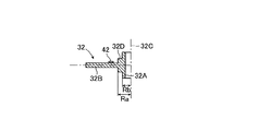
ハブ部材20はブレーキロータディスク22の円板部22Aと共働してホイール支持部材として機能し、フランジ部28は円板部22Aと共働してホイール支持部を郭定している。円板部16Aと円板部22Aとの間には回転軸線14と同軸にて円環状の弾性体32が配置されている。弾性体32は回転軸線14の周りに互いに90°隔置された四つの実質的に円筒状の柱状部32Aと、柱状部32Aと一体をなし柱状部の周りに延在する板状部32Bとを有している。板状部32Bは柱状部32Aの長手方向の両端の端面の間の中央部に設けられている。
The
尚ハブ部材20及びブレーキロータディスク22は鉄合金の如き高強度且つ高剛性の金属材料にて形成され、ホイール16はアルミニウム合金や鉄合金の如き強度及び剛性が比較的高い金属材料にて形成され、弾性体32はアルミニウム合金の如き弾性が比較的高い金属材料にて形成されていてよい。
The
柱状部32Aの軸線32Cは回転軸線14と平行に延在し、柱状部32Aは両端の端面にて円板部16A及び円板部22Aに当接している。板状部32Bは回転軸線14の周りに環状に且つ回転軸線14に垂直に延在し、四つの柱状部32Aを一体に接続している。また板状部32Bはハブ部材20の軸部26よりも大きい内径を有し、ブレーキロータディスク22の円板部22Aよりも小さい外径を有している。
The
また円板部16Aと円板部22Aとの間にはカバー部材34が配置されている。カバー部材34は互いに一体をなす円板部34A及び円筒部34Bを有している。円板部34Aは柱状部32Aを密に受ける孔34Cを有し、円板部16Aに当接している。円筒部34Bは弾性体32の周りにて回転軸線14と平行に延在し、円板部34Aとは反対側の端部にて円板部22Aに当接している。円筒部34Bの端面には円板部22Aとの間を経てカバー部材34の内部へ泥水や粉塵が侵入することを阻止するOリングシール35が配設されている。
A
各柱状部32Aには軸線32Cに沿って延在する断面円形の孔36が設けられており、各孔36には連結手段としてのボルト38が挿通されている。各ボルト38の軸線は軸線32Cに沿ってこれに整合して延在している。各ボルト38のヘッド部はフランジ部28の内面に固定されている。図示の実施例に於いては、孔36はボルト38を遊嵌状態にて受け入れる大径部と、ボルト38を実質的に密に受け入れる小径部とを有している。
Each
各ボルト38はハブ部材20のフランジ部28、ブレーキロータディスク22の円板部22A、弾性体32の柱状部32A、ホイール16の円板部16Aを貫通して円板部16Aの外部まで延在している。弾性体32及びカバー部材34はボルト38及びそれに螺合するナット40により、円板部16Aと円板部22Aとの間に圧縮され、円板部16Aはフランジ部28及びブレーキロータディスク22と強固に一体的に連結されている。
Each
弾性体32の板状部32Bは円板部22A及び円板部34Aより隔置されており、板状部32Bの外側の表面には柱状部32Aに近接して検出素子42が固定されている。図2に示されている如く、各柱状部32Aについて見て、検出素子42は軸線32Cに対し車輪の径方向に垂直な方向の位置、即ち回転軸線14及び軸線32Cを通る平面44に垂直な直線46上の位置に設けられている。図示の実施例に於いては、検出素子42は板状部32Bの厚さの中心に対し同一の側にて直線46に沿う方向の各柱状部32Aの両側に設けられている。
The plate-
図3に変形を誇張して示されている如く、車輪10とハブ部材20との間に作用するトルクに起因して円板部16A及び円板部22Aが回転軸線14の周りに相対回転すると、弾性体32の柱状部32Aは剪断応力を受け、軸線32Cは円板部16A及び22Aに対し傾斜する。そのため柱状部32Aの周方向両側の板状部32Bは弾性的に湾曲変形し、凹状の表面部は圧縮変形するのに対し凸状の表面部は引張り変形する。
As the deformation is exaggerated in FIG. 3, when the
板状部32Bの弾性変形量は柱状部32Aが受ける剪断応力に比例し、柱状部32Aが受ける剪断応力はボルト38を介して車輪10とハブ部材20との間に伝達されるトルクに比例する。よって柱状部32Aの両側に於ける板状部32Bの弾性変形量を検出することにより、柱状部32Aの位置に於いてボルト38が円板部16Aと円板部22Aとの間に伝達する周方向の力を推定することができる。
The amount of elastic deformation of the
各検出素子42は抵抗線式の歪ゲージの如く板状部32Bの直線46に沿う方向の弾性歪に応じた電流値の電流信号を出力し、これにより各ボルト38の周方向両側に於いて直線46に沿って板状部32Bの表面部に作用する応力を検出する応力検出手段として機能する。カバー部材34は回転軸線14に整合する小径部48を有し、小径部48にはハブ部材20の軸部26の外端が部分的に嵌合している。カバー部材34の中央部内には演算手段としての電子回路装置50が配置されている。各検出素子42より出力される電流信号は導線52を経て電子回路装置50へ供給される。
Each
尚板状部32Bの表面部を凹状に圧縮変形させる応力及び凸状に伸び変形させる応力は大きさが同一で方向が逆の応力であると考えられる。また板状部32Bの表裏の変形は互いに逆の関係にある。よって各柱状部32Aに対応して設けられた一対の検出素子42は、板状部32Bの同一の側の面について直線46に沿う互いに逆の方向を正の方向として弾性歪を検出する。
In addition, it is thought that the stress which compresses and deforms the surface part of the plate-shaped
電子回路装置50は、後に説明する如く、各検出素子42より入力される電流信号に基づいて各ボルト38の位置に於いて円板部16Aと円板部22Aとの間に作用する周方向の力Fx1〜Fx4を演算し、それらの力に基づいてタイヤ18の接地点の中心Pに於いて路面56よりタイヤ18に作用する回転軸線14に垂直な前後方向の応力(前後力)Fxtを演算し、応力Fxtを示す信号を図には示されていない車両の制御装置へ出力する。
As will be described later, the
図4は第一の実施例に於いて各検出素子42により検出される応力を車輪10のアウトボード側より見た状態にて示す説明図である。図4に示されている如く、四つのボルト38を38a〜38dとし、ボルト38a〜38dに対し反時計廻り方向の側に配置された検出素子42により検出される応力をそれぞれfx11、fx21、fx31、fx41とする。またボルト38a〜38dに対し時計廻り方向の側に配置された検出素子42により検出される応力をそれぞれfx12、fx22、fx32、fx42とする。
FIG. 4 is an explanatory view showing the stress detected by each
電子回路装置50は、ボルト38a〜38dの中心に車輪10の回転方向に作用する応力Fx1〜Fx4をそれぞれ下記の式1〜4に従って演算する。
Fx1=(fx11+fx12)/2 ……(1)
Fx2=(fx21+fx22)/2 ……(2)
Fx3=(fx31+fx32)/2 ……(3)
Fx4=(fx41+fx42)/2 ……(4)
The
Fx1 = (fx11 + fx12) / 2 (1)
Fx2 = (fx21 + fx22) / 2 (2)
Fx3 = (fx31 + fx32) / 2 (3)
Fx4 = (fx41 + fx42) / 2 (4)
車輪10の回転半径、回転軸線14と軸線38Cとの間の距離等により決定される係数をAx(正の定数)とすると、タイヤ18の接地点の中心Pに於いて路面56よりタイヤ18に作用する前後力Fxtは下記の式5により表される。よって電子回路装置50は下記の式5に従ってタイヤ18に作用する前後力Fxtを演算する。
Fxt=Ax(Fx1+Fx2+Fx3+Fx4) ……(5)
Assuming that the coefficient determined by the rotation radius of the
Fxt = Ax (Fx1 + Fx2 + Fx3 + Fx4) (5)
尚車輪10に作用する上下方向の力により柱状部32Aは上下方向の剪断力を受け、各検出素子42より検出される力fx11〜fx41及びfx12〜fx42には上下方向の剪断力による誤差成分が含まれる。しかし上下方向の剪断力による誤差成分の方向は車輪10の回転軸線14に対し水平方向の両側に於いて互いに逆の方向であるので、上記式5の演算により上下方向の剪断力による誤差成分を消去することができる。
The
また車輪10に作用する横力により柱状部32Aは上下方向の曲げ応力を受け、各検出素子42より検出される力fx11〜fx41及びfx12〜fx42には上下方向の曲げ応力による誤差成分が含まれる。しかし上下方向の曲げ応力による誤差成分の方向は車輪10の回転軸線14に対し上下方向の両側に於いて互いに逆の方向であるので、上記式1〜5の演算により上下方向の曲げ応力による誤差成分を消去することができる。
Further, the
よって車輪10に作用する上下方向の力や横力の影響を受けることなくタイヤ18に作用する前後力Fxtを正確に演算することができ、この作用効果は後述の他の実施例に於いても同様に得られる。
Therefore, the longitudinal force Fxt acting on the
かくして図示の第一の実施例によれば、ホイール16若しくはハブ部材20にトルクが作用すると、弾性体32の柱状部32Aに剪断応力が作用し、その際の板状部32Bの弾性変形に伴う歪に基づいて各ボルト38の位置に作用する車輪10の回転方向の応力Fx1〜Fx4を求めることができ、またこれらの応力に基づいて路面56よりタイヤ18に作用する前後力Fxtを正確に演算することができる。
Thus, according to the first embodiment shown in the drawing, when a torque acts on the
特に第一の実施例によれば、円板部16Aと円板部22Aとの間にはカバー部材34が配置され、カバー部材34は円板部16A及び22Aより受ける圧縮応力の少なくとも一部を担持し、弾性体32の柱状部32Aに作用する圧縮応力を制限する圧縮応力制限手段として機能する。
In particular, according to the first embodiment, the
従ってカバー部材34によって柱状部32Aに作用する圧縮応力が制限されない場合に比して、ホイール16の円板部16Aとハブ部材20のフランジ部28との強固な連結を確保しつつ弾性体32の剛性を低くすることができ、これにより車輪10の良好な支持剛性を確保しつつタイヤ作用力の検出精度を高くすることができる。尚この作用効果は後述の第四及び第五の実施例に於いても同様に得られる。
Therefore, as compared with the case where the compressive stress acting on the
また第一の実施例によれば、一対の検出素子42が各柱状部32Aに対し車輪10の周方向の両側にて板状部32Bの同一の側の表面に設けられており、ボルト38a〜38dの中心に車輪10の回転方向に作用する応力Fx1〜Fx4は上記式1〜4に従って各一対の検出素子42により検出される応力の平均値として演算される。
Further, according to the first embodiment, a pair of
従って各柱状部32Aの近傍に一つの検出素子42しか設けられていない場合に比して、各柱状部32Aの位置にて弾性体32に作用する応力Fx1〜Fx4を正確に求めることができ、また検出素子42が一部の柱状部32Aにしか設けられていない場合に比して、タイヤ18に作用する前後力Fxtを正確に演算することができる。尚この作用効果は後述の他の実施例に於いても同様に得られる。
Therefore, compared with the case where only one
また第一の実施例によれば、各柱状部32Aは板状部32Bにより互いに一体に接続されており、弾性体32は一つの部品である。従って板状部32Bが柱状部32Aの周りに部分的にしか延在せず、四つの柱状部32Aが板状部32Bにより一体に接続されていない場合に比して、弾性体32の部品点数を低減することができると共に、弾性体32の組み付けを容易に行うことができる。この作用効果は第四の実施例を除く後述の他の実施例に於いても同様に得られる。
Further, according to the first embodiment, the
また第一の実施例によれば、各柱状部32Aは孔36の小径部にてボルト38に実質的に密に係合している。従って各柱状部32Aの軸線32Cをボルト38の軸線に容易に且つ確実に整合させることができ、これにより弾性体32を円板部16A及び22Aに対し容易に且つ確実に位置決めすることができると共に、各柱状部32Aの位置にて弾性体32に作用する応力Fx1〜Fx4を正確に求めることができる。
Further, according to the first embodiment, each
尚図示の第一の実施例に於いては、カバー部材34は弾性体32の柱状部32Aに作用する圧縮応力を制限する圧縮応力制限手段としても機能するようになっているが、圧縮応力制限手段として機能しないよう修正されてもよい。即ち各柱状部32Aがカバー部材34の円板部34Aを貫通して延在することにより、カバー部材34が円板部16A及び22Aより受ける圧縮応力を担持しないよう修正されてもよい。
[第二の実施例]
In the illustrated first embodiment, the
[Second Example]
図5は本発明によるタイヤ作用力検知装置の第二の実施例を車輪の回転軸線を通る切断面(図6の線V−V)にて切断して示す断面図、図6は第二の実施例の要部を図5の線VI−VIにて切断して示す断面図、図7は第二の実施例の弾性体を図6の線VII−VIIにて切断して示す断面図である。 FIG. 5 is a sectional view showing a tire working force detection device according to a second embodiment of the present invention cut along a cutting plane (line V-V in FIG. 6) passing through the rotation axis of the wheel, and FIG. FIG. 7 is a cross-sectional view showing the main part of the embodiment cut along line VI-VI in FIG. 5, and FIG. 7 is a cross-sectional view showing the elastic body in the second embodiment cut along line VII-VII in FIG. is there.
尚図5乃至図7に於いて図1及び図2に示された部材と同一の部材には図1及び図2に於いて付された符号と同一の符号が付されており、この第二の実施例について説明する点以外の構造は、上述の第一の実施例の構造と同一である。このことは後述の他の実施例についても同様である。 5 to 7, the same members as those shown in FIGS. 1 and 2 are denoted by the same reference numerals as those shown in FIGS. The structure other than that described in this embodiment is the same as that in the first embodiment described above. The same applies to other embodiments described later.
この第二の実施例に於いては、上述の第一の実施例に於けるカバー部材34に相当する部材は設けられていない。また弾性体32の柱状部32Aに設けられた孔36はその全長に亘り一定の直径を有し、その直径はボルト38の直径よりも大きく、これにより孔36は遊嵌状態にてボルト38を受け入れるようになっている。
In the second embodiment, no member corresponding to the
弾性体32の柱状部32Aは車輪10の径方向に沿って延在する断面長円形をなし、長径以外の領域に於いては断面円形の台座部32Dを介して板状部32Bに接続されている。台座部32Dの厚さは柱状部32Aの軸線32Cに沿う長さよりも小さく且つ板状部32Bの厚さよりも大きい。また台座部32Dの半径Raは柱状部32Aの長径の2分の1の長さと同一であり、従って柱状部32Aの短径の2分の1の長さRbよりも大きい値に設定されている。
The
各柱状部32Aは径方向内側の端部に位置決め突起58を有し、位置決め突起58は柱状部32Aより径方向内方へ延在している。位置決め突起58の先端は内部に電子回路装置50を収容するキャップ部材60の外周面に当接し、これにより弾性体32の軸線が回転軸線14に整合し且つ各孔36が対応するボルト38に整合した状態に位置決めされるようになっている。
Each
更に板状部32Bは円板部16A及び円板部22Aより隔置されており、板状部32Bには周方向に互いに隣接する二つの柱状部32Aの間の位置にスリット62が設けられている。スリット62は孔36の軸線32Cを通る仮想の円弧線に対する接線に平行に検出素子42に近接する位置まで直線的に延在している。またスリット62は板状部32Bの全厚に亘り板状部32Bの厚さ方向に延在し、スリット62の両端は二等辺三角形の形状をなしている。
Furthermore, the plate-
従って弾性体32に応力が作用し、板状部32Bが弾性変形する際に、細長い六角形をなすスリット62、特にその両端の部分に応力が集中し、検出素子42が設けられた領域に於ける板状部32Bの弾性変形量が増大する。よってスリット62は板状部32Bに作用する応力を集中させることにより検出素子42が設けられた領域に於ける板状部32Bの歪を増大させる応力集中部を構成している。
Therefore, when the stress is applied to the
尚スリット62は細長い六角形に限定されるものではなく、検出素子42が設けられた領域に於ける板状部32Bの歪を増大させることができる限り、ひし形や三角形の如き任意の形状であってよい。また周方向に互いに隣接する二つの柱状部32Aの間に設けられるスリット62の数は一つに限定されるものではなく、例えば各検出素子42に近接してスリット62が一つずつ設けられてもよい。更に板状部32Bの厚さは第一の実施例に於ける厚さよりも大きい値に設定されていてよい。
The
かくして図示の第二の実施例によれば、上述の第一の実施例の場合と同様に、板状部32Bの歪に基づいて各ボルト38の位置に作用する車輪10の回転方向の応力Fx1〜Fx4を求め、これらの応力に基づいて路面56よりタイヤ18に作用する前後力Fxtを正確に演算することができる。
Thus, according to the second embodiment shown in the drawing, as in the case of the first embodiment described above, the stress Fx1 in the rotational direction of the
特に図示の第二の実施例によれば、柱状部32Aは車輪10の径方向に沿って延在する断面長円形をなし、長径以外の領域に於いては断面円形の台座部32Dを介して板状部32Bに接続されている。従って台座部32Dが設けられていない場合に比して板状部32Bの弾性変形量が小さいので、他の実施例の場合に比して弾性体32に要求される剛性を低くすることができる。
In particular, according to the second embodiment shown in the figure, the
また第二の実施例によれば、板状部32Bには周方向に互いに隣接する二つの柱状部32Aの間の位置にスリット62が設けられ、スリット62は板状部32Bに作用する応力を集中させる応力集中部として機能する。
Further, according to the second embodiment, the plate-
従って検出素子42が設けられた領域に於ける板状部32Bの歪がスリット62によって増大されるので、スリット62が設けられていない場合に比して板状部32Bの板厚を大きい値に設定することができる。よって弾性体32を輸送したり組み付けたりする際の板状部32Bの余分な変形を低減することができる。
Accordingly, since the distortion of the plate-
また第二の実施例によれば、位置決め突起58の先端はキャップ部材60の外周面に当接し、これにより弾性体32の位置決めが行われる。従って位置決め突起58が設けられていない場合に比して、弾性体32の軸線が回転軸線14に整合し且つ各孔36が対応するボルト38に整合した状態になるよう、弾性体32を容易に且つ正確に位置決めすることができる。
[第三の実施例]
Further, according to the second embodiment, the distal end of the
[Third embodiment]
図8は本発明によるタイヤ作用力検知装置の第三の実施例を車輪の回転軸線を通る切断面(図9の線VIII−VIII)にて切断して示す断面図、図9は第三の実施例の弾性体の要部を図8の線IX−IXにて切断して示す断面図である。 FIG. 8 is a cross-sectional view showing a third embodiment of the tire acting force detection device according to the present invention cut along a cutting plane (line VIII-VIII in FIG. 9) passing through the rotation axis of the wheel, and FIG. It is sectional drawing which cut | disconnects and shows the principal part of the elastic body of an Example by the line IX-IX of FIG.
この第三の実施例は上述の第二の実施例の修正例として構成されており、この第三の実施例に於いては、弾性体32の柱状部32Aは円筒形をなしている。また弾性体32の板状部32Bは上述の第一の実施例の場合と同様に円環板状をなし、内部に電子回路装置50を収容するキャップ部材60の外径よりも大きい内径を有している。
This third embodiment is configured as a modification of the above-described second embodiment, and in this third embodiment, the
各柱状部32Aに設けられた孔36は上述の第二の実施例の場合と同様にその全長に亘り一定の直径を有し、その直径はボルト38の直径と実質的に同一又はこれよりも僅かに大きく、これにより孔36は圧入状態になることなくボルト38を実質的に密に受け入れるようになっている。
The
また板状部32Bには上述の第二の実施例に於けるスリット62の如き応力集中部が設けられておらず、板状部32Bの厚さは第二の実施例に於ける厚さよりも小さい値に設定されている。尚第二の実施例の場合と同様、板状部32Bは円板部16A及び円板部22Aより隔置されている。
Further, the plate-
かくして図示の第三の実施例によれば、上述の第一及び第二の実施例の場合と同様に、板状部32Bの歪に基づいて各ボルト38の位置に作用する車輪10の回転方向の応力Fx1〜Fx4を求め、これらの応力に基づいて路面56よりタイヤ18に作用する前後力Fxtを正確に演算することができる。
Thus, according to the third embodiment shown in the drawing, the rotation direction of the
特に第三の実施例によれば、柱状部32Aは単純な円柱状であり、板状部32Bは単純な円環状であってよい。従って他の実施例の場合に比して弾性体32の形状を単純化し、弾性体32を低廉に製造することができる。
In particular, according to the third embodiment, the
また第三の実施例によれば、各柱状部32Aが対応するボルト38に実質的に密に嵌合するので、特別な位置決め手段を要することなく、弾性体32の軸線を回転軸線14に整合させると共に、柱状部32Aの軸線32Cをボルト38の軸線に整合させることができる。尚弾性体32は各柱状部32Aが対応するボルト38に少なくとも部分的に遊嵌合するよう修正されてもよい。
[第四の実施例]
Further, according to the third embodiment, each
[Fourth embodiment]
図10は本発明によるタイヤ作用力検知装置の第四の実施例を車輪の回転軸線を通る切断面(図11の線X−X)にて切断して示す断面図、図11は第四の実施例の要部を図10の線XI−XIにて切断して示す断面図、図12は第四の実施例の要部を図10の線XII−XIIにて切断して示す部分断面図である。 FIG. 10 is a cross-sectional view showing a fourth embodiment of the tire acting force detection device according to the present invention cut along a cutting plane (line X-X in FIG. 11) passing through the rotation axis of the wheel. FIG. FIG. 12 is a partial cross-sectional view showing the main part of the embodiment cut along line XI-XI in FIG. 10, and FIG. 12 is a partial cross-sectional view showing the main part of the fourth embodiment cut along line XII-XII in FIG. It is.
この第四の実施例は上述の第一の実施例の修正例として構成されており、この第四の実施例に於いては、上述の第一の実施例の場合と同様にカバー部材34が設けられている。しかし弾性体32は回転軸線14の周りに延在する環状をなしておらず、車輪10の回転軸線14の周りに互いに90°周方向に隔置された位置に四つの弾性体32が配置されている。
The fourth embodiment is configured as a modification of the first embodiment described above. In the fourth embodiment, the
弾性体32の柱状部32Aはカバー部材34の円板部34Aを貫通しておらず、円板部34Aとブレーキロータディスク22の円板部22Aとの間に僅かに圧縮された状態にて配置されている。柱状部32Aは円筒形をなしているが、板状部32Bは柱状部32Aの周りの狭い範囲にのみ延在している。尚第一の実施例の場合と同様、板状部32Bは円板部22A及び円板部34Aより隔置されている。
The
また各弾性体32の板状部32Bはそれと一体をなし直線46に沿って延在する一対の帯状の支持部64を有し、各弾性体32は径方向の直線44に対し対称形をなしている。カバー部材34の円板部34Aの内面には柱状部32Aより直線46に沿って隔置された位置に支持台座66が一体に設けられている。
The plate-shaped
支持部64の先端は支持台座66に設けられた溝に圧入式に嵌め込まれており、これにより各弾性体32は柱状部32Aの孔36がブレーキロータディスク22の円板部22A及びカバー部材34の円板部34Aに設けられたボルト38を受ける孔に整合した状態で支持台座66により支持されている。円板部22A及び34Aの孔はボルト38を密に受け入れる直径を有しているが、孔36はボルト38を遊嵌状態にて受け入れる直径を有している。
The tip of the
更に電子回路装置50はカバー部材34内には収容されておらず、電子回路装置50を収容するキャップ部材60が部分的にハブ部材20の軸部26に嵌入した状態にてカバー部材34の円板部34Aと軸部26との間に配置されている。
Further, the
かくして図示の第四の実施例によれば、上述の第一乃至第三の実施例の場合と同様に、板状部32Bの歪に基づいて各ボルト38の位置に作用する車輪10の回転方向の応力Fx1〜Fx4を求め、これらの応力に基づいて路面56よりタイヤ18に作用する前後力Fxtを正確に演算することができる。
Thus, according to the fourth embodiment shown in the drawing, the rotation direction of the
特に第四の実施例によれば、各弾性体32は支持部64の先端が支持台座66に設けられた溝に圧入式に嵌め込まれることによりカバー部材34の円板部34Aに固定されている。従って各弾性体32の柱状部32Aの孔36を円板部22A及び34Aに設けられたボルト38を受ける孔に確実に整合させることができ、これにより柱状部32Aの軸線32Cを確実にボルト38の軸線に整合させることができる。
In particular, according to the fourth embodiment, each
また第四の実施例によれば、各柱状部32Aはその全長に亘りボルト38に遊嵌合しているので、柱状部32Aが少なくとも部分的にボルト38に密に嵌合している場合に比して、ボルト38が柱状部32A及び板状部32Bの弾性変形を阻害することを確実に防止することができる。
Further, according to the fourth embodiment, each
また第四の実施例によれば、四つの弾性体32が設けられ、それらが互いに独立している。従って四つの柱状部32Aが一つの円環板状の板状部32Bにより一体に接続されている他の実施例の場合に比して、互いに隣接する柱状部32Aがその周囲の板状部32Bの弾性変形に影響を及ぼすことを確実に防止することができる。
[第五の実施例]
According to the fourth embodiment, four
[Fifth embodiment]
図13は本発明によるタイヤ作用力検知装置の第五の実施例を車輪の回転軸線を通る切断面(図14の線XIII−XIII)にて切断して示す断面図、図14は第五の実施例の要部を図13の線XIV−XIVにて切断して示す断面図である。 FIG. 13 is a cross-sectional view showing a fifth embodiment of the tire acting force detection device according to the present invention cut along a cutting plane (line XIII-XIII in FIG. 14) passing through the rotational axis of the wheel, and FIG. It is sectional drawing which cut | disconnects and shows the principal part of an Example by the line XIV-XIV of FIG.
この第五の実施例は上述の第三の実施例の修正例として構成されており、この第五の実施例に於いては、上述の第三の実施例の場合と同様に弾性体32の柱状部32Aは円筒形をなしている。また弾性体32の板状部32Bは上述の第一の実施例の場合と同様に円環板状をなし、内部に電子回路装置50を収容するキャップ部材60の外径よりも大きい内径を有している。尚柱状部32Aは筒形ではなく、充実の柱状をなしていてもよい。
This fifth embodiment is configured as a modification of the above-described third embodiment. In this fifth embodiment, the
また上述の第三の実施例の場合と同様に柱状部32Aは車輪10の回転軸線14の周りに互いに90°周方向に隔置された位置に設けられているが、ボルト38を遊嵌状態にて受ける孔68は柱状部32Aに対し回転軸線14の周りに互いに45°周方向に隔置された位置に設けられている。
Further, as in the case of the third embodiment described above, the
また第四の実施例の場合と同様、各柱状部32Aは端部の端面にて円板部22A及び円板部34Aに当接し、板状部32Bは円板部22A及び円板部34Aより隔置されている。
Similarly to the case of the fourth embodiment, each
かくして図示の第五の実施例によれば、上述の第一乃至第四の実施例の場合と同様に、板状部32Bの歪に基づいて各柱状部32Aの位置に作用する車輪10の回転方向の応力Fx1〜Fx4を求め、これらの応力に基づいて路面56よりタイヤ18に作用する前後力Fxtを正確に演算することができる。
Thus, according to the illustrated fifth embodiment, as in the first to fourth embodiments described above, the rotation of the
特に第五の実施例によれば、各柱状部32Aはボルト38に嵌合せず、ボルト38より車輪10の周方向に隔置されている。従って各柱状部32Aの位置がボルト38の位置の制約を受けることなく、路面56よりタイヤ18に作用する前後力Fxtを演算することができる。
In particular, according to the fifth embodiment, each
また第五の実施例によれば、ボルト38は板状部32Bに設けられた孔に密に嵌合しているので、弾性体32の軸線を確実に回転軸線14に整合させることができると共に、各柱状部32Aを容易に且つ正確に所定の位置に位置決めすることができる。
Further, according to the fifth embodiment, since the
以上に於いては本発明を特定の実施例について詳細に説明したが、本発明は上述の実施例に限定されるものではなく、本発明の範囲内にて他の種々の実施例が可能であることは当業者にとって明らかであろう。 Although the present invention has been described in detail with reference to specific embodiments, the present invention is not limited to the above-described embodiments, and various other embodiments are possible within the scope of the present invention. It will be apparent to those skilled in the art.
例えば上述の第二及び第三の実施例に於いては、カバー部材は設けられていないが、第一の実施例等に於けるカバー部材34と同様のカバー部材が設けられてもよく、逆に第一、第四及び第五の実施例に於いてカバー部材34が省略されてもよい。
For example, in the second and third embodiments described above, the cover member is not provided, but a cover member similar to the
また上述の第一の実施例に於いては、柱状部32Aがカバー部材34を貫通して延在しているが、第四及び第五の実施例の場合と同様に、柱状部32Aの対応する端部の端面がカバー部材34の円板部34Aに当接していてもよい。逆に第四及び第五の実施例に於いて、第一の実施例の場合と同様に、柱状部32Aがカバー部材34を貫通して延在していてもよい。
Further, in the first embodiment described above, the
また上述の第二及び第三の実施例に於いては、弾性体32の柱状部32Aに作用する圧縮応力を制限する圧縮応力制限手段は設けられていないが、これらの実施例に於いても圧縮応力制限手段は設けられていてもよい。例えばキャップ部材60にホイール16の円板部16Aに当接する肩部を設けることにより、キャップ部材60が弾性体32の柱状部32Aに作用する圧縮応力を制限する圧縮応力制限手段として機能するよう構成されてもよい。
In the second and third embodiments described above, no compressive stress limiting means for limiting the compressive stress acting on the
また上述の各実施例に於いては、柱状部32Aの断面形状は円形又は長円形を成しているが、多角形や楕円の如き任意の形状であってよい。同様に第四の実施例を除く各実施例に於いては、板状部32Bは円環板状をなしているが、多角形の如き任意の形状であってよい。
In each of the above-described embodiments, the cross-sectional shape of the
また上述の各実施例に於いては、弾性体32の温度に基づく応力の補正は行われないようになっているが、弾性体32の温度、特に板状部32Bの温度が検出されると共に、検出された温度に基づいて応力Fx11等又は車輪10の回転方向に作用する応力Fx1〜Fx4が補正されるよう修正されてもよい。
In each of the embodiments described above, stress correction based on the temperature of the
また上述の各実施例に於いては、路面56よりタイヤ18に作用する上下力は演算されないようになっているが、各柱状部32Aの両側に設けられた一対の検出素子42により検出される応力の差は車輪10の回転に伴って正弦波状に変化するので、応力の差の正弦波状に変化に基づいて行列演算により路面56よりタイヤ18に作用する上下力が演算されてもよい。
In each of the above-described embodiments, the vertical force acting on the
10…車輪、12…タイヤ作用力検知装置、14…回転軸線、16…ホイール、18…タイヤ、20…ハブ部材、22…ブレーキロータディスク、32…弾性体、32A…柱状部、32B…板状部、34…カバー部材、38…ボルト、42…検出素子、50…電子回路装置、56…路面、60…キャップ部材、62…スリット、66…支持台座
DESCRIPTION OF
Claims (8)
前記円板部と前記ホイール支持部との間に配置された弾性体であって、前記回転軸線と平行に延在し両端の端面にて前記円板部及び前記ホイール支持部に当接する柱状部と、前記両端の端面の間にて前記柱状部と一体をなし前記柱状部の周りに延在する板状部とを備え、前記板状部は前記円板部及び前記ホイール支持部より隔置された弾性体と、
前記板状部の歪を検出することにより前記弾性体に作用する応力を検出する応力検出手段と、
検出された応力に基づいてタイヤ作用力を演算する演算手段と、
を有することを特徴とするタイヤ作用力検出装置。 A wheel having a disc portion perpendicular to the rotation axis, a wheel having a tire held on the outer periphery of the wheel, and a wheel support portion that is supported by the vehicle body so as to be rotatable around the rotation axis and is perpendicular to the rotation axis A vehicle comprising: a wheel support member that rotatably supports the wheel around the rotation axis; and a connecting unit that connects the disk portion of the wheel and the wheel support portion of the wheel support member. In the tire action force detection device for detecting the tire action force acting on the contact point of the tire,
A columnar portion disposed between the disk portion and the wheel support portion, the columnar portion extending in parallel with the rotation axis and contacting the disk portion and the wheel support portion at both end faces . And a plate-like part that is integrated with the columnar part between the end faces of the both ends and extends around the columnar part , the plate-like part being spaced apart from the disk part and the wheel support part and an elastic body that is,
Stress detecting means for detecting stress acting on the elastic body by detecting strain of the plate-like portion;
A computing means for computing the tire acting force based on the detected stress ;
A tire acting force detection device comprising:
Priority Applications (6)
| Application Number | Priority Date | Filing Date | Title |
|---|---|---|---|
| JP2008308305A JP4860680B2 (en) | 2008-12-03 | 2008-12-03 | Tire acting force detection device |
| EP09801250A EP2352980A1 (en) | 2008-12-03 | 2009-12-01 | Tire force detection apparatus |
| RU2011122470/11A RU2471162C1 (en) | 2008-12-03 | 2009-12-01 | Device for determining force on tyre |
| US13/132,450 US8567240B2 (en) | 2008-12-03 | 2009-12-01 | Tire force detection apparatus |
| PCT/IB2009/007621 WO2010064123A1 (en) | 2008-12-03 | 2009-12-01 | Tire force detection apparatus |
| CN200980148779.9A CN102239398B (en) | 2008-12-03 | 2009-12-01 | Tire force detection apparatus |
Applications Claiming Priority (1)
| Application Number | Priority Date | Filing Date | Title |
|---|---|---|---|
| JP2008308305A JP4860680B2 (en) | 2008-12-03 | 2008-12-03 | Tire acting force detection device |
Publications (2)
| Publication Number | Publication Date |
|---|---|
| JP2010133760A JP2010133760A (en) | 2010-06-17 |
| JP4860680B2 true JP4860680B2 (en) | 2012-01-25 |
Family
ID=41820321
Family Applications (1)
| Application Number | Title | Priority Date | Filing Date |
|---|---|---|---|
| JP2008308305A Expired - Fee Related JP4860680B2 (en) | 2008-12-03 | 2008-12-03 | Tire acting force detection device |
Country Status (6)
| Country | Link |
|---|---|
| US (1) | US8567240B2 (en) |
| EP (1) | EP2352980A1 (en) |
| JP (1) | JP4860680B2 (en) |
| CN (1) | CN102239398B (en) |
| RU (1) | RU2471162C1 (en) |
| WO (1) | WO2010064123A1 (en) |
Cited By (3)
| Publication number | Priority date | Publication date | Assignee | Title |
|---|---|---|---|---|
| WO2016158587A1 (en) * | 2015-03-30 | 2016-10-06 | Ntn株式会社 | Vehicle wheel fastening status determination device |
| WO2016186030A1 (en) * | 2015-05-19 | 2016-11-24 | Ntn株式会社 | Device for determining wheel fastening state using server |
| JP2017047837A (en) * | 2015-09-04 | 2017-03-09 | Ntn株式会社 | Wheel fastening state determination device |
Families Citing this family (6)
| Publication number | Priority date | Publication date | Assignee | Title |
|---|---|---|---|---|
| CN102393309B (en) * | 2011-08-25 | 2014-04-16 | 吉林大学 | Tyre coupling stiffness testing machine |
| JP6084893B2 (en) * | 2013-05-08 | 2017-02-22 | 富士重工業株式会社 | Wheel component detection device |
| WO2016135994A1 (en) * | 2015-02-25 | 2016-09-01 | 東日本旅客鉄道株式会社 | Structure for strain detection |
| EP3671141B1 (en) * | 2018-12-20 | 2022-08-03 | Bizerba SE & Co. KG | Load cell and weighing foot |
| CN110646075A (en) * | 2019-10-08 | 2020-01-03 | 中信戴卡股份有限公司 | Deformation sensor and device for measuring vehicle hub load and automobile |
| FR3104251B1 (en) | 2019-12-09 | 2023-06-09 | Commissariat Energie Atomique | Wireless electronic detonator comprising a power switch controlled by an optical signal, wireless detonation system and method for activating such a detonator. |
Family Cites Families (23)
| Publication number | Priority date | Publication date | Assignee | Title |
|---|---|---|---|---|
| DE2856453A1 (en) | 1978-12-28 | 1980-07-10 | Volkswagenwerk Ag | MEASURING HUB |
| JPS5597542A (en) * | 1979-01-18 | 1980-07-24 | Daikin Mfg Co Ltd | Damper disk |
| JPS5793833A (en) * | 1980-11-28 | 1982-06-11 | Iseki & Co Ltd | Apparatus of grain dryer |
| JPS5793833U (en) | 1980-12-01 | 1982-06-09 | ||
| JP2731856B2 (en) * | 1989-02-17 | 1998-03-25 | 株式会社共和電業 | Wheel side force measuring device |
| DE4133418C2 (en) * | 1991-10-09 | 1993-11-04 | Daimler Benz Ag | MULTI-COMPONENT DISC WHEEL |
| US5445036A (en) | 1994-06-15 | 1995-08-29 | The University Of British Columbia | Torque sensor |
| DE4435160A1 (en) * | 1994-09-30 | 1996-04-04 | Continental Ag | Device for determining the peripheral force of a vehicle wheel |
| JPH1048072A (en) * | 1996-08-01 | 1998-02-20 | Ono Sokki Co Ltd | Torque measuring instrument |
| DE19650477C1 (en) * | 1996-12-05 | 1998-04-30 | Daimler Benz Ag | Vehicle braking torque measuring device for disc brakes in automobile |
| ATE381004T1 (en) | 1998-04-07 | 2007-12-15 | Pirelli | METHOD FOR DETERMINING THE ROAD BEHAVIOR OF A VEHICLE TIRE |
| JP3669421B2 (en) * | 2000-04-25 | 2005-07-06 | 日産自動車株式会社 | Torque measuring device |
| JP4779246B2 (en) | 2001-06-28 | 2011-09-28 | トヨタ自動車株式会社 | Tire acting force detection device |
| EP1275949B1 (en) | 2001-07-10 | 2008-09-24 | Société de Technologie Michelin | Tyre incorporating a measuring device |
| JPWO2003008246A1 (en) * | 2001-07-19 | 2004-11-04 | 株式会社ブリヂストン | Road friction coefficient estimation method, signal multiplex transmission method, and signal multiplex transmission device |
| US6943674B2 (en) * | 2003-11-26 | 2005-09-13 | Ching-Song Tsai | Tire pressure indicator |
| FR2863205B1 (en) * | 2003-12-08 | 2006-02-17 | Michelin Soc Tech | PNEUMATIC INFLATION METHOD, DEVICE AND MACHINE FOR IMPLEMENTING THE METHOD |
| JP2005241470A (en) | 2004-02-26 | 2005-09-08 | Denso Corp | Detector and method for detecting force acting on tire |
| JP4072688B2 (en) | 2004-03-03 | 2008-04-09 | トヨタ自動車株式会社 | Tire acting force detection device |
| US7140242B1 (en) * | 2004-07-22 | 2006-11-28 | Akron Special Machinery | Lateral load tire testing system |
| CN2757113Y (en) * | 2004-12-01 | 2006-02-08 | 旭东机械(昆山)有限公司 | Tyre detector |
| JP2007040782A (en) * | 2005-08-02 | 2007-02-15 | Toyota Motor Corp | Wheel acting force detection system and wheel acting force detection method |
| CN101669017B (en) * | 2007-04-25 | 2012-06-27 | 丰田自动车株式会社 | Tire action force detecting device |
-
2008
- 2008-12-03 JP JP2008308305A patent/JP4860680B2/en not_active Expired - Fee Related
-
2009
- 2009-12-01 CN CN200980148779.9A patent/CN102239398B/en not_active Expired - Fee Related
- 2009-12-01 US US13/132,450 patent/US8567240B2/en not_active Expired - Fee Related
- 2009-12-01 RU RU2011122470/11A patent/RU2471162C1/en not_active IP Right Cessation
- 2009-12-01 WO PCT/IB2009/007621 patent/WO2010064123A1/en active Application Filing
- 2009-12-01 EP EP09801250A patent/EP2352980A1/en not_active Withdrawn
Cited By (7)
| Publication number | Priority date | Publication date | Assignee | Title |
|---|---|---|---|---|
| WO2016158587A1 (en) * | 2015-03-30 | 2016-10-06 | Ntn株式会社 | Vehicle wheel fastening status determination device |
| JP2016187977A (en) * | 2015-03-30 | 2016-11-04 | Ntn株式会社 | Wheel fastening state determining device |
| WO2016186030A1 (en) * | 2015-05-19 | 2016-11-24 | Ntn株式会社 | Device for determining wheel fastening state using server |
| JP2016215787A (en) * | 2015-05-19 | 2016-12-22 | Ntn株式会社 | Server use determination device of wheel fastening state |
| US10408709B2 (en) | 2015-05-19 | 2019-09-10 | Ntn Corporation | Device for determining wheel fastening state using server |
| JP2017047837A (en) * | 2015-09-04 | 2017-03-09 | Ntn株式会社 | Wheel fastening state determination device |
| WO2017038803A1 (en) * | 2015-09-04 | 2017-03-09 | Ntn株式会社 | Wheel fastening state assessing device |
Also Published As
| Publication number | Publication date |
|---|---|
| WO2010064123A1 (en) | 2010-06-10 |
| CN102239398A (en) | 2011-11-09 |
| JP2010133760A (en) | 2010-06-17 |
| US8567240B2 (en) | 2013-10-29 |
| CN102239398B (en) | 2014-04-09 |
| RU2471162C1 (en) | 2012-12-27 |
| US20110239752A1 (en) | 2011-10-06 |
| EP2352980A1 (en) | 2011-08-10 |
Similar Documents
| Publication | Publication Date | Title |
|---|---|---|
| JP4860680B2 (en) | Tire acting force detection device | |
| WO2007066482A1 (en) | Sensor-equipped bearing for wheel | |
| WO2007066593A1 (en) | Sensor-equipped bearing for wheel | |
| CN101326431A (en) | Wheel bearing with sensor | |
| US7793556B2 (en) | Torque sensor for a steering wheel | |
| JP4925624B2 (en) | Wheel bearing with sensor | |
| JP2007071280A (en) | Wheel bearing with sensor | |
| JP5455357B2 (en) | Tire acting force detection device | |
| JP6692691B2 (en) | Measuring device | |
| JP2008051283A (en) | Wheel bearing with sensor | |
| JP2007057300A (en) | Wheel bearing with sensor | |
| WO2009119068A1 (en) | Sensor-equipped bearing for wheel | |
| JP2007078615A (en) | Bearing with sensor for wheel | |
| JP2007153226A (en) | Bearing device for wheel | |
| JP2008303892A (en) | Wheel bearing with sensor | |
| JP5072551B2 (en) | Wheel bearing with sensor | |
| JP2008213561A (en) | Wheel bearing with sensor | |
| JP6385215B2 (en) | Wheel force detection device | |
| JP4911967B2 (en) | Wheel bearing with sensor | |
| JP2007057301A (en) | Wheel bearing with sensor | |
| JP2008249566A (en) | Sensor-attached wheel bearing | |
| JP4925770B2 (en) | Wheel bearing with sensor | |
| JP4493569B2 (en) | Wheel bearing with sensor | |
| JP5224805B2 (en) | Wheel bearing with sensor | |
| JP2007078597A (en) | Bearing with sensor for wheel |
Legal Events
| Date | Code | Title | Description |
|---|---|---|---|
| A977 | Report on retrieval |
Free format text: JAPANESE INTERMEDIATE CODE: A971007 Effective date: 20101224 |
|
| A131 | Notification of reasons for refusal |
Free format text: JAPANESE INTERMEDIATE CODE: A131 Effective date: 20110111 |
|
| A521 | Request for written amendment filed |
Free format text: JAPANESE INTERMEDIATE CODE: A523 Effective date: 20110208 |
|
| A131 | Notification of reasons for refusal |
Free format text: JAPANESE INTERMEDIATE CODE: A131 Effective date: 20110705 |
|
| A521 | Request for written amendment filed |
Free format text: JAPANESE INTERMEDIATE CODE: A523 Effective date: 20110901 |
|
| TRDD | Decision of grant or rejection written | ||
| A01 | Written decision to grant a patent or to grant a registration (utility model) |
Free format text: JAPANESE INTERMEDIATE CODE: A01 Effective date: 20111018 |
|
| A01 | Written decision to grant a patent or to grant a registration (utility model) |
Free format text: JAPANESE INTERMEDIATE CODE: A01 |
|
| A61 | First payment of annual fees (during grant procedure) |
Free format text: JAPANESE INTERMEDIATE CODE: A61 Effective date: 20111102 |
|
| FPAY | Renewal fee payment (event date is renewal date of database) |
Free format text: PAYMENT UNTIL: 20141111 Year of fee payment: 3 |
|
| LAPS | Cancellation because of no payment of annual fees |