JP4854582B2 - Image processing apparatus and image processing method - Google Patents
Image processing apparatus and image processing method Download PDFInfo
- Publication number
- JP4854582B2 JP4854582B2 JP2007115989A JP2007115989A JP4854582B2 JP 4854582 B2 JP4854582 B2 JP 4854582B2 JP 2007115989 A JP2007115989 A JP 2007115989A JP 2007115989 A JP2007115989 A JP 2007115989A JP 4854582 B2 JP4854582 B2 JP 4854582B2
- Authority
- JP
- Japan
- Prior art keywords
- image
- eye
- chroma key
- pixel
- virtual space
- Prior art date
- Legal status (The legal status is an assumption and is not a legal conclusion. Google has not performed a legal analysis and makes no representation as to the accuracy of the status listed.)
- Expired - Fee Related
Links
Images


Classifications
-
- H—ELECTRICITY
- H04—ELECTRIC COMMUNICATION TECHNIQUE
- H04N—PICTORIAL COMMUNICATION, e.g. TELEVISION
- H04N9/00—Details of colour television systems
- H04N9/64—Circuits for processing colour signals
- H04N9/74—Circuits for processing colour signals for obtaining special effects
- H04N9/75—Chroma key
-
- H—ELECTRICITY
- H04—ELECTRIC COMMUNICATION TECHNIQUE
- H04N—PICTORIAL COMMUNICATION, e.g. TELEVISION
- H04N13/00—Stereoscopic video systems; Multi-view video systems; Details thereof
- H04N13/10—Processing, recording or transmission of stereoscopic or multi-view image signals
Landscapes
- Engineering & Computer Science (AREA)
- Multimedia (AREA)
- Signal Processing (AREA)
- Studio Circuits (AREA)
- Processing Of Color Television Signals (AREA)
- Processing Or Creating Images (AREA)
- Image Processing (AREA)
- Editing Of Facsimile Originals (AREA)
Description
本発明は、クロマキー合成技術に関するものである。 The present invention relates to a chroma key composition technique.
クロマキー合成とは、特定色を有する領域以外の領域を抜き出した画像を、もう一つの画像上に上書きすることにより、画像同士を合成する技術である。 The chroma key composition is a technique for compositing images by overwriting an image obtained by extracting an area other than an area having a specific color on another image.
クロマキー合成を正確に行うためには、特定色を有する領域を正確に検出することが必要である。特に特定色を有する領域の輪郭線は、合成した画像を美しく見せるためには正確に検出することが求められる。 In order to accurately perform chroma key composition, it is necessary to accurately detect a region having a specific color. In particular, it is necessary to accurately detect the contour line of a region having a specific color in order to make the synthesized image look beautiful.
従来、クロマキー合成の為に、輪郭線を正確に検出するための技術として、特許文献1に開示されているように、特定色を有する領域の大体の位置を色情報から求め、その輪郭を輝度情報から求めるような手法が提案されていた。
しかしながら、従来のクロマキー合成では、特定色を有する領域を含む画像にノイズが無いことを仮定しており、ノイズのある場合には適用が難しかった。 However, in the conventional chroma key composition, it is assumed that there is no noise in an image including a region having a specific color, and it is difficult to apply when there is noise.
画像にノイズが生じる例としては、画像を無線で転送する場合が挙げられる。画像を無線で伝送した場合、伝送中に空電ノイズを拾ってしまうと、画像に欠損(ノイズ)が生じてしまう。 An example where noise occurs in an image is when the image is transferred wirelessly. When an image is transmitted wirelessly, if static noise is picked up during transmission, a defect (noise) occurs in the image.
しかも、画像中にノイズがあると、画像の色が本来の色と異なってしまい、クロマキー合成時に特定色を有する領域を検出する際、この検出に失敗してしまうことがある。そのため、正常にクロマキー合成を行うことができないことがあった。 Moreover, if there is noise in the image, the color of the image is different from the original color, and this detection may fail when detecting a region having a specific color during chroma key composition. For this reason, the chroma key composition may not be performed normally.
本発明は以上の問題に鑑みてなされたものであり、クロマキー色を有する領域を含む画像にノイズ等が生じても、この画像を他の画像を用いて補正することで、このノイズ等を除去し、正確なクロマキー合成を実現する為の技術を提供することを目的とする。 The present invention has been made in view of the above problems, and even when noise or the like occurs in an image including a region having a chroma key color, the noise or the like is removed by correcting the image using another image. The object is to provide a technique for realizing accurate chroma key composition.
本発明の目的を達成するために、例えば、本発明の画像処理装置は以下の構成を備える。 In order to achieve the object of the present invention, for example, an image processing apparatus of the present invention comprises the following arrangement.
即ち、現実空間画像を取得する現実空間画像の取得手段と、
予め設定されたクロマキー色を有する画素群で構成されているクロマキー領域を含む仮想空間画像を取得する仮想空間画像の取得手段と、
前記仮想空間画像に含まれるクロマキー色に基づいて、前記現実空間画像に対する前記仮想空間画像のクロマキー合成を行う合成手段と、
前記合成手段によるクロマキー合成処理で生成した合成画像を、表示装置に対して出力する出力手段と
を備える画像処理装置であって、
前記仮想空間画像中の前記クロマキー領域と非クロマキー領域との境界部分にエラー箇所が存在するか否かを、前記仮想空間画像の取得手段が前記仮想空間画像の他に取得した他仮想空間画像を用いて判断する判断手段と、
前記エラー箇所が存在すると前記判断手段が判断したエラー箇所を、前記他仮想空間画像のクロマキー領域を用いて補正する補正手段と
を備えることを特徴とする。
That is, a real space image acquisition means for acquiring a real space image,
A virtual space image acquisition means for acquiring a virtual space image including a chroma key region composed of a group of pixels having a preset chroma key color;
Synthesis means for performing chroma key composition of the virtual space image with respect to the real space image based on a chroma key color included in the virtual space image;
An image processing apparatus comprising: output means for outputting a composite image generated by the chroma key composition processing by the composition means to a display device;
Whether error part exists at the boundary between the chroma key region and non-chroma key region in the virtual space image, the other virtual space image acquired acquiring means of the virtual space image is in addition to the virtual space image Judgment means to judge using ,
Correction means for correcting the error location determined by the determination means that the error location exists using a chroma key region of the other virtual space image .
本発明の目的を達成するために、例えば、本発明の画像処理方法は以下の構成を備える。 In order to achieve the object of the present invention, for example, an image processing method of the present invention comprises the following arrangement.
即ち、現実空間画像を取得する現実空間画像の取得手段と、
予め設定されたクロマキー色を有する画素群で構成されているクロマキー領域を含む仮想空間画像を取得する仮想空間画像の取得手段と、
前記仮想空間画像に含まれるクロマキー色に基づいて、前記現実空間画像に対する前記仮想空間画像のクロマキー合成を行う合成手段と、
前記合成手段によるクロマキー合成処理で生成した合成画像を、表示装置に対して出力する出力手段と
を備える画像処理装置が行う画像処理方法であって、
前記画像処理装置の判断手段が、前記仮想空間画像中の前記クロマキー領域と非クロマキー領域との境界部分にエラー箇所が存在するか否かを、前記仮想空間画像の取得手段が前記仮想空間画像の他に取得した他仮想空間画像を用いて判断する判断工程と、
前記画像処理装置の補正手段が、前記エラー箇所が存在すると前記判断工程で判断したエラー箇所を、前記他仮想空間画像のクロマキー領域を用いて補正する補正工程と
を備えることを特徴とする。
That is, a real space image acquisition means for acquiring a real space image,
A virtual space image acquisition means for acquiring a virtual space image including a chroma key region composed of a group of pixels having a preset chroma key color;
Synthesis means for performing chroma key composition of the virtual space image with respect to the real space image based on a chroma key color included in the virtual space image;
An image processing method performed by an image processing apparatus comprising: output means for outputting a composite image generated by chroma key composition processing by the composition means to a display device;
The determination unit of the image processing apparatus determines whether or not there is an error location at a boundary portion between the chroma key region and the non-chroma key region in the virtual space image, and the acquisition unit of the virtual space image A determination step of determining using other acquired virtual space images ;
The correction unit of the image processing apparatus includes a correction step of correcting the error location determined in the determination step when the error location exists using a chroma key region of the other virtual space image .
本発明の構成によれば、クロマキー色を有する領域を含む画像にノイズ等が生じても、この画像を他の画像を用いて補正することで、このノイズ等を除去したクロマキー合成を実現することができる。 According to the configuration of the present invention, even if noise or the like occurs in an image including an area having a chroma key color, the chroma key composition can be realized by removing the noise or the like by correcting the image using another image. Can do.
以下、添付図面を参照し、本発明の好適な実施形態について詳細に説明する。 Hereinafter, preferred embodiments of the present invention will be described in detail with reference to the accompanying drawings.
[第1の実施形態]
本実施形態で用いるCG(コンピュータグラフィックス)画像(仮想空間画像)には、予め設定されたクロマキー色を有する画素群で構成されている領域(クロマキー領域)が存在している。そして本実施形態では、ユーザの右目に提示するために生成したCG画像(仮想空間画像)と現実空間画像とをクロマキー合成したものを、このユーザの右目に対して提示する。更に、左目に提示するために生成したCG画像(仮想空間画像)と現実空間画像とをクロマキー合成したものを、このユーザの左目に対して提示する。
[First Embodiment]
In a CG (computer graphics) image (virtual space image) used in the present embodiment, there is an area (chroma key area) configured by a pixel group having a preset chroma key color. In this embodiment, a chroma key composition of a CG image (virtual space image) generated for presentation to the right eye of the user and a real space image is presented to the right eye of the user. Further, a CG image (virtual space image) generated for presentation to the left eye and a real space image, which are subjected to chroma key composition, are presented to the user's left eye.
そして本実施形態では、係る構成を前提として、次のような構成を有していることを特徴とする。即ち、一方の目に提示する為に生成したCG画像中のクロマキー領域と非クロマキー領域との境界部分に、クロマキー処理時にエラー箇所が生じても、それぞれの目に提示するCG画像は類似しているという性質を利用し、それぞれの目に対して良好なクロマキー合成結果を提示する。 The present embodiment is characterized by having the following configuration on the premise of such a configuration. That is, even if an error occurs at the boundary between the chroma key area and the non-chroma key area in the CG image generated for presentation to one eye, the CG image presented to each eye is similar. Using this property, a good chroma key composition result is presented for each eye.
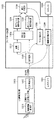
図1は、本実施形態に係るシステムを、ユーザが使用している様子を示す図である。係るシステムの構成自体は、周知のMR(Mixed Reality)システムである。 FIG. 1 is a diagram illustrating a state in which a user is using the system according to the present embodiment. The system configuration itself is a well-known MR (Mixed Reality) system.
図1において1000は、画像処理装置としてのビデオシースルー型のHMD(ヘッドマウントディスプレイ)であり、周知の頭部装着型表示装置で構成することができる。2000は、係るHMD1000を頭部に装着しているユーザである。HMD1000の詳細な構成については後述するが、HMD1000には、ユーザ2000の右目に画像を提示するための画面、左目に画像を提示するための画面が設けられている。従ってユーザ2000は、右目、左目でそれぞれの画面を見ることで、それぞれの目に対応した画像を眼前に見ることができる。
In FIG. 1,
3000はコンピュータ(計算機)であり、ユーザ2000の右目に提示する為のCG画像(右目用CG画像)、左目に提示する為のCG画像(左目用CG画像)を生成する。そして生成したそれぞれのCG画像を無線でHMD1000に送信する。なお、CG画像を送信する際、無線帯域を小さくするために、送信するそれぞれのCG画像を圧縮してから送信する。圧縮されたCG画像はHMD1000側で伸張してから用いる。
A computer (computer) 3000 generates a CG image (right-eye CG image) for presentation to the right eye of the
ここで、計算機3000によって圧縮された状態で右目用CG画像、左目用CG画像を、無線でHMD1000に送信し、HMD1000側でこれらのCG画像を受信して取り扱う場合、取り扱うCG画像にノイズが重畳されている(画像情報の欠損も含む)ケースが生じうる。これは上述の通り、無線でCG画像を送信したり、圧縮されたCG画像を伸張したりすることに起因する。特に、CG画像中には上述の通り、クロマキー領域が存在している。従って、係るクロマキー領域と非クロマキー領域との境界部分にノイズが生じる(境界部分にエラー箇所が生じる)と、このCG画像を現実空間画像とクロマキー合成しても、係る境界部分における合成結果にもノイズが生じてしまう。
Here, when the CG image for the right eye and the CG image for the left eye are wirelessly transmitted to the HMD 1000 in a state compressed by the
本実施形態では、右目用CG画像と左目用CG画像とが類似した画像であるという性質を利用し、例え一方側のCG画像におけるクロマキー領域と非クロマキー領域との境界部分にエラー箇所が生じても、他方のCG画像を用いて係るエラー箇所を補正する。これにより、良好なクロマキー合成結果を得ることにある。 In the present embodiment, using the property that the right-eye CG image and the left-eye CG image are similar to each other, for example, an error portion is generated at the boundary portion between the chroma key region and the non-chroma key region in the CG image on one side. Also, the error location is corrected using the other CG image. This is to obtain a good chroma key composition result.
図3は、一般的なクロマキー合成処理を説明する図である。図3において300は現実空間画像である。301はCG画像で、斜線部分はクロマキー領域である。302は、CG画像301と現実空間画像300とをクロマキー合成したことで得られる画像(合成画像)である。即ち、CG画像301を現実空間画像300上に重ね合わせる場合に、クロマキー領域については透過させて合成させたものが、合成画像302となる。
FIG. 3 is a diagram for explaining a general chroma key composition process. In FIG. 3, 300 is a real space image.
図4は、HMD1000の機能構成を示すブロック図である。図4に示す如く、HMD1000は大まかにはCG画像受信部1010、左目カメラ1001、右目カメラ1002、クロマキー合成部1100、左目LCD(液晶画面)1003、右目LCD1004により構成されている。
FIG. 4 is a block diagram showing a functional configuration of the HMD 1000. As shown in FIG. As shown in FIG. 4, the HMD 1000 roughly includes a CG
図2は、HMD1000の外観例を示す図である。図2に示す如く、左目LCD1003、右目LCD1004のそれぞれの近傍位置にはそれぞれ、左目カメラ1001、右目カメラ1002が装着されている。左目カメラ1001、右目カメラ1002はそれぞれ、現実空間の動画像を撮像するものであり、撮像した各フレームの画像は、図4に示すクロマキー合成部1100に入力される。
FIG. 2 is a diagram showing an example of the appearance of the
先ず、図4に示したHMD1000の構成のうち、CG画像受信部1010について説明する。
First, the CG
図4に示す如く、CG画像受信部1010は、無線画像受信部1011、左目伸張部1012、右目伸張部1013により構成されている。
As shown in FIG. 4, the CG
計算機3000(外部装置)から無線で送信された、右目用CG画像(圧縮済み)、左目用CG画像(圧縮済み)は、無線画像受信部1011で受信される。無線画像受信部1011は受信した右目用CG画像、左目用CG画像をそれぞれ、右目伸張部1013、左目伸張部1012に転送する。
The right-eye CG image (compressed) and the left-eye CG image (compressed) transmitted wirelessly from the computer 3000 (external device) are received by the wireless
ここで、上述の通り、無線画像受信部1011が受信した右目用CG画像、左目用CG画像には、無線通信に起因したノイズが重畳されている可能性がある。また、無線画像受信部1011は、無線通信によって受信した情報に欠損が生じた場合には、周知の技術で係る欠損を補間したりするので、計算機3000から送信したCG画像と、無線画像受信部1011から送出されるCG画像とには差が生じうる。
Here, as described above, noise due to wireless communication may be superimposed on the right-eye CG image and the left-eye CG image received by the wireless
左目伸張部1012は、圧縮済みの左目用CG画像を伸張し、伸張後の左目用CG画像を、後段の左目色判定部1101、左目画像切り替え部1109に送出する。右目伸張部1013も同様に、圧縮済みの右目用CG画像を伸張し、伸張後の右目用CG画像を、後段の右目色判定部1102、右目画像切り替え部1111に送出する。
The left-
ここで、上述の通り、左目伸張部1012、右目伸張部1013のそれぞれが伸張したCG画像には、画像伸張に起因するノイズが重畳されている可能性がある。
Here, as described above, there is a possibility that noise due to image expansion is superimposed on the CG image expanded by each of the left
次に、クロマキー合成部1100について説明する。図4に示す如く、クロマキー合成部1100は、左目色判定部1101、右目色判定部1102、対応点検出部1103、左目傾き検出部1104、右目傾き検出部1105、誤り判定部1106、補正箇所判定部1107を有している。更に、クロマキー合成部1100は、左目マスク補正部1108、左目画像切り替え部1109、右目マスク補正部1110、右目画像切り替え部1111を有する。
Next, the chroma
最初に、クロマキー合成部1100の基本的な動作、即ち、CG画像に対するノイズを考慮せずに、従来通りのクロマキー合成処理を行う場合の、クロマキー合成部1100の動作について、図4,5を用いて説明する。図5は、クロマキー合成部1100が行うクロマキー合成処理を示す図である。
First, the basic operation of the chroma
左目伸張部1012から送出された伸張済みの左目用CG画像は上述の通り、左目色判定部1101、左目画像切り替え部1109に対して送出される。
The stretched left-eye CG image sent from the left-
左目色判定部1101は、伸張済みの左目用CG画像を構成する各画素の画素値を参照し、参照した画素値が、予め設定されたクロマキー色を示すか否かをチェックする。そして、クロマキー色を示す画素値を有する画素に対してはビット「1」を割り当て、クロマキー色を示さない画素値を有する画素に対してはビット「0」を割り当てる。
The left eye
例えば、画素値が8ビットで構成されている場合、クロマキー色をR=0,G=0,B>250と規定しても良い。この場合、左目色判定部1101は、左目用CG画像を構成する各画素のうち、R=0、G=0、B>250を満たす画素値を有する画素に対してはビット「1」を割り当て、満たさない画素値を有する画素に対してはビット「0」を割り当てる。即ち、左目色判定部1101は、左目用CG画像においてクロマキー領域内の画素の画素値を「1」、クロマキー領域外の画素の画素値を「0」に置き換えた2値画像を生成することになる。以下ではこの2値画像を「マスク画像」と呼称する。尚、このマスク画像は、必ずしも1画面分持つ必要は無く、処理に必要な数ライン分のバッファに選択用画像として記憶することでも充分である。
For example, when the pixel value is composed of 8 bits, the chroma key color may be defined as R = 0, G = 0, B> 250. In this case, the left-eye
図5において500はCG画像であり、斜線部分がクロマキー領域である。従ってこの場合、斜線部分を構成する各画素に対してはビット「1」を割り当て、斜線部分以外を構成する各画素に対してはビット「0」を割り当てる。503は、係るビットの集合で構成されているマスク画像である。
In FIG. 5,
一方、右目色判定部1102には、右目伸張部1013から送出された、伸張済みの右目用CG画像が入力されるので、右目色判定部1102は左目色判定部1101と同様の処理を行い、右目用CG画像に対応するマスク画像を生成する。
On the other hand, since the expanded right-eye CG image sent from the right-
左目色判定部1101が生成したマスク画像は対応点検出部1103、左目マスク補正部1108に入力され、右目色判定部1102が生成したマスク画像(マスク画像)は対応点検出部1103、右目マスク補正部1110に入力される。ここではクロマキー合成処理の基本的な説明を行っているので、左目マスク補正部1108、右目マスク補正部1110による補正処理は行わないものとする。従って、左目マスク補正部1108は、受けたマスク画像をそのまま左目画像切り替え部1109に送出するし、右目マスク補正部1110は、受けたマスク画像をそのまま右目画像切り替え部1111に送出する。
The mask image generated by the left eye
一方、左目カメラ1001は上述の通り、ユーザ2000の左目に対して提示する現実空間の動画像を撮像するためのものであり、撮像した各フレームの画像(現実空間画像)は順次、左目画像切り替え部1109に入力される。また、右目カメラ1002は上述の通り、ユーザ2000の右目に対して提示する現実空間の動画像を撮像するためのものであり、撮像した各フレームの画像(現実空間画像)は順次、右目画像切り替え部1111に入力される。図5において、501は、カメラによって撮像された現実空間画像である。
On the other hand, as described above, the left-
左目画像切り替え部1109は、左目色判定部1101から受けたマスク画像を用いて、左目伸張部1012から受けた左目用CG画像と、左目カメラ1001から受けた現実空間画像とのクロマキー合成を行う。即ち、クロマキー合成によって生成する合成画像のx(1≦x≦X)番目の画素として、左目用CG画像のx番目の画素を用いるのか、現実空間画像のx番目の画素を用いるのかを、マスク画像のx番目の画素に対するビット値に基づいて決定する。ここでXは左目用CG画像(右目用CG画像、合成画像についても同じ)の全画素数を示す。
The left-eye
マスク画像におけるx番目の画素のビット値が「1」である場合には、合成画像におけるx番目の画素として、現実空間画像におけるx番目の画素を用いる。一方、マスク画像におけるx番目の画素のビット値が「0」である場合には、合成画像におけるx番目の画素として、左目用CG画像におけるx番目の画素を用いる。このようにして、マスク画像を構成する各ビット値に応じて、左目用CG画像、現実空間画像から選択的に画素を選択し、合成画像における画素とすることで、合成画像を生成することができる。なお、係るクロマキー合成処理については周知のものであるので、これ以上の説明は省略する。 When the bit value of the xth pixel in the mask image is “1”, the xth pixel in the real space image is used as the xth pixel in the composite image. On the other hand, when the bit value of the xth pixel in the mask image is “0”, the xth pixel in the left-eye CG image is used as the xth pixel in the composite image. In this manner, a composite image can be generated by selectively selecting a pixel from the left-eye CG image and the real space image according to each bit value constituting the mask image, and using the pixel as a pixel in the composite image. it can. Since the chroma key composition process is well known, further explanation is omitted.
図5において504はクロマキー合成による合成画像である。
In FIG. 5,
一方、右目画像切り替え部1111は左目画像切り替え部1109と同様の処理を行う。即ち、右目色判定部1102から受けたマスク画像を用いて、右目伸張部1013から受けた右目用CG画像と、右目カメラ1002から受けた現実空間画像とのクロマキー合成を行う。
On the other hand, the right eye
そして、左目画像切り替え部1109によって生成した合成画像は左目LCD1003に送出し、右目画像切り替え部1111によって生成した合成画像は右目LCD1004に送出する。これによりユーザ2000の左目、右目の眼前に、それぞれの目に対応する合成画像が表示されることになる。そして係る合成画像は、右目用、左目用の何れであっても、CG画像におけるクロマキー領域が、現実空間画像において対応する領域に置き換わったものとなる。
The composite image generated by the left-eye
次に、クロマキー領域と非クロマキー領域との境界部分にエラー箇所が発生しても、右目用CG画像と左目用CG画像とは類似した画像であるという性質を利用し、良好なクロマキー合成結果を得る為のクロマキー合成部1100の動作について説明する。
Next, even if an error occurs at the boundary between the chroma key area and the non-chroma key area, a good chroma key composition result is obtained by utilizing the property that the right-eye CG image and the left-eye CG image are similar images. The operation of the chroma
図6は、CG画像(左目用CG画像、右目用CG画像の何れでも良い)中の画像情報が欠損したことにより、このCG画像上にノイズが重畳された例を示す図である。図6に示す如く、CG画像中のポット600の取っ手の一部分近傍を拡大すると、クロマキー領域の一部(黒塗り部分)における画像情報が欠損しており、欠損した部分を構成する各画素の画素値は、R=0、G=0、B>250とはなっていない。即ち、係る部分は、クロマキー領域ではなくなっている。
FIG. 6 is a diagram illustrating an example in which noise is superimposed on the CG image due to loss of image information in the CG image (which may be either a left-eye CG image or a right-eye CG image). As shown in FIG. 6, when the vicinity of a part of the handle of the
従って、係るCG画像と現実空間画像とのクロマキー合成を行うと、この黒塗り部分の部分は、CG画像の画素値がそのまま残り、合成画像上でノイズ(エラー箇所)として残ることになる。本実施形態では、係るエラー箇所を補正し、良好なクロマキー合成結果を得ることを目的とする。より具体的には、左目用CG画像と右目用CG画像とを比較し、一方側にエラー箇所があれば、他方のCG画像を用いてこのエラー箇所を補正する。 Therefore, when the chroma key composition between the CG image and the real space image is performed, the pixel value of the CG image remains as it is in this black portion, and it remains as noise (error part) on the composite image. An object of the present embodiment is to correct such an error part and obtain a good chroma key composition result. More specifically, the left-eye CG image and the right-eye CG image are compared, and if there is an error location on one side, the error location is corrected using the other CG image.
ここで、本実施形態に係るエラー箇所の補正方法について簡単に説明する。図7は、エラー箇所の補正について説明する図である。図7において790は左目用CG画像から生成したマスク画像(左目用マスク画像)において、クロマキー領域と隣接する非クロマキー領域の一部分(画素群)である。また、780は右目用CG画像から生成したマスク画像(右目用マスク画像)において、クロマキー領域と隣接する非クロマキー領域の一部分(画素群)である。画素群780中において斜線部分で示している画素群は、エラー箇所である。
Here, a method for correcting an error location according to the present embodiment will be briefly described. FIG. 7 is a diagram for explaining correction of an error location. In FIG. 7,
先ず、画素群790のうちクロマキー領域と接する画素720における、境界部分の傾き(700で示す直線の傾き)を求める。そして、画素群780において、画素720と位置的に対応する画素(対応画素)における、境界部分の傾き(701で示す直線の傾き)を求める。ここで、左目用CG画像と右目用CG画像とは類似している画像であるので、それぞれの傾きはほぼ同じであると考えるのが自然である。従って、それぞれの傾きに大きな差がある場合、左目用CG画像、右目用CG画像の何れかにエラー箇所があると考えるのが自然である。
First, the inclination of the boundary portion (inclination of a straight line indicated by 700) in the
更に、左目用CG画像、右目用CG画像の何れにエラー箇所があるのかを判定するためには、画素720よりも前に、画素群790のうちクロマキー領域と接する画素として選択された1以上の画素のそれぞれについて求めた傾きを参照する。そして、画素720について求めた傾きと、画素720より1つ前に選択された画素について求めた傾きとの差、画素720について求めた傾きと、画素720より2つ前に選択された画素について求めた傾きとの差、というように、幾つかの差を求める。そして、差の変化が予め定めた変化以上であるのかをチェックする。
Further, in order to determine which of the left-eye CG image and the right-eye CG image has an error location, one or more pixels selected as pixels in contact with the chroma key region in the
同様に、対応画素よりも前に、画素群780のうちクロマキー領域と接する画素として選択された1以上の画素のそれぞれについて求めた傾きを参照する。そして、対応画素について求めた傾きと、対応画素より1つ前に選択された画素について求めた傾きとの差、対応画素について求めた傾きと、対応画素より2つ前に選択された画素について求めた傾きとの差、というように、幾つかの差を求める。そして、差の変化が予め定めた変化以上であるのかをチェックする。
Similarly, the slope obtained for each of one or more pixels selected as pixels in contact with the chroma key area in the
そして、画素群790側でのチェックと、画素群780側でのチェックとを行った結果、差の変化が予め定めた変化以上であると判定した方に、エラー箇所があると判断する。図7では、画素群780側にエラー箇所がある。従ってこの場合、対応画素における傾きが、直線700の傾きとなるように、エラー箇所を補正する。
Then, as a result of performing the check on the
以下では、係る処理をより具体的に説明する。なお、以下説明する動作は、上記基本的な動作に加えて行うものである。 Hereinafter, the processing will be described more specifically. The operation described below is performed in addition to the above basic operation.
対応点検出部1103は、左目色判定部1101、右目色判定部1102からそれぞれ送出された左目用マスク画像、右目用マスク画像を受ける。そして、一方のマスク画像上の非クロマキー領域(ビット値が「0」の領域)において、クロマキー領域(ビット値が「1」の領域)と隣接する部分を構成している各画素と位置的に対応する、他方のマスク画像上の画素位置(対応位置)を特定する。対応点検出部1103が行う画素位置特定処理については従来から様々な手法が提案されており、本実施形態では何れの手法を用いても良いのであるが、例えば、以下説明するような手法を用いても良い。
The corresponding
先ず、以下の点を仮定する。 First, assume the following points.
・ 左目カメラ1001、右目カメラ1002は理想的に並行に配置されており、エピポーラ線は左右の画像の同じライン上にある。
The left-
・ CG画像においてクロマキー領域以外の領域(即ち仮想物体の画像)は画面の端にかからない。 In the CG image, the area other than the chroma key area (that is, the image of the virtual object) does not reach the edge of the screen.
このような仮定を前提とすることで、左目用マスク画像、右目用マスク画像をライン毎に比較するだけで、対応する画素の検出を行うことができる。 Based on this assumption, it is possible to detect the corresponding pixels only by comparing the left-eye mask image and the right-eye mask image for each line.
対応点検出部1103は、右目用マスク画像、左目用マスク画像を受けると先ず、それぞれのマスク画像で同じラインを参照し、ライン上における非クロマキー領域を特定する。
When the corresponding
図8は、右目用マスク画像、左目用マスク画像のそれぞれで同じラインを参照した場合に、ライン上における非クロマキー領域を特定する処理を説明する図である。なお、図8を用いて後述する処理は右目用マスク画像、左目用マスク画像の何れに対しても同じであるので、係る説明では右目用マスク画像を例に取り説明する。 FIG. 8 is a diagram illustrating processing for specifying a non-chroma key region on a line when the same line is referenced in each of the right-eye mask image and the left-eye mask image. Note that the processing described later with reference to FIG. 8 is the same for both the right-eye mask image and the left-eye mask image. Therefore, in the description, the right-eye mask image will be described as an example.
図8(a)は、右目用マスク画像800の一例を示す図である。図8(a)では、右目用マスク画像800は横サイズを640画素としている。右目用マスク画像800において810,820はそれぞれ非クロマキー領域(ビット値が「0」の領域)であり、それ以外の領域はクロマキー領域(ビット値が「1」の領域)である。
FIG. 8A shows an example of the right-
対応点検出部1103は、右目用マスク画像800中のライン830を処理する場合、先ず、ライン830を構成する各画素を一方から順に参照する。そして、非クロマキー領域の開始位置、終了位置(画素値が「0」である画素が連続して配されている画素列の開始位置、終了位置)を検出する。
When the corresponding
図8(b)は、ライン830を構成する各画素の分布を示す図である。図8(b)に示す如く、非クロマキー領域を構成する画素群は、x=60〜180、340〜500に分布している。従って、図8(c)に示す如く、ライン830上では、x=60〜180に非クロマキー領域が存在していることを示すために、開始位置の欄には「60」を登録し、対応する終了位置の欄には「180」を登録する。同様に、もう1つの非クロマキー領域がx=340〜500に存在していることを示すために、開始位置の欄には「340」を登録し、対応する終了位置の欄には「500」を登録する。
FIG. 8B is a diagram showing the distribution of each pixel constituting the
このように、非クロマキー領域毎に、その開始位置と終了位置とをセットにして登録する。係るテーブルは、ライン毎に生成されるものであるので、例えば、右目用マスク画像800のライン数が480であったとすると、係るテーブルは480個生成されることになる。しかし、非クロマキー領域が存在しないラインについては係るテーブルは作成されないので、この場合には、作成されるテーブルの数は480よりも少なくなる。
Thus, for each non-chroma key area, the start position and end position are registered as a set. Since such a table is generated for each line, for example, if the number of lines in the right-
なお、図8(c)では、テーブル形式で開始位置と終了位置とを登録しているが、データの管理形態についてはこれに限定するものではない。 In FIG. 8C, the start position and end position are registered in a table format, but the data management form is not limited to this.
上述の通り、対応点検出部1103は、係る処理を左目用マスク画像についても行うので、結果として、図8(c)に例示したテーブルが、左目用マスク画像に対しても生成されることになる。ここで、右目用マスク画像について生成したテーブルを右目用テーブル、左目用マスク画像について生成したテーブルを左目用テーブルと呼称する。
As described above, the corresponding
この場合、右目用テーブルにおいてm(m≧1)行目に登録されている開始位置、終了位置で特定される非クロマキー領域と、左目用テーブルにおいてm行目に登録されている開始位置、終了位置で特定される非クロマキー領域とは対応しているものとして扱う。そして、対応点検出部1103は、左目用テーブルのm行目に登録されている開始位置、終了位置を左目傾き検出部1104に送出すると共に、右目用テーブルのm行目に登録されている開始位置、終了位置を右目傾き検出部1105に送出する。
In this case, the non-chroma key area specified by the start position and end position registered in the m (m ≧ 1) line in the right eye table, and the start position and end registered in the m line in the left eye table. The non-chroma key area specified by the position is handled as corresponding. Then, the corresponding
以下の説明ではm=nの場合について説明する。 In the following description, a case where m = n will be described.
左目傾き検出部1104は、左目用テーブルのn行目に登録されている開始位置、終了位置を受けると、開始位置、終了位置における、クロマキー領域と非クロマキー領域との境界部分の傾きを求める。ここで、左目傾き検出部1104が行う処理の詳細について、図9を用いて説明する。
When the left eye
図9は、非クロマキー領域(斜線で示した部分)を構成する各画素と、クロマキー領域を構成する各画素と、を示す図である。同図において900は、左目用テーブルのn行目に登録されている開始位置で特定される画素位置であるとする。901は、画素900とx座標値が同じ1ライン上の位置からx座標値が小さい方向に画素値を参照した場合に、参照した画素値が「1」となる1つ手前の位置における画素である。902は、画素900とx座標値が同じ2ライン上の位置からx座標値が小さい方向に画素値を参照した場合に、参照した画素値が「1」となる1つ手前の位置における画素である。
FIG. 9 is a diagram illustrating each pixel constituting a non-chroma key area (a portion indicated by oblique lines) and each pixel constituting a chroma key area. In the figure, 900 is a pixel position specified by the start position registered in the nth row of the left eye table.
ここで、画素900の位置における傾きを求めるためには、先ず、画素900の位置と画素901の位置とを通る直線の傾きを求めると共に、画素900の位置と画素902の位置とを通る直線の傾きを求める。そしてそれぞれの傾きの平均値を求め、求めた平均値を、画素900の位置における傾きとしている。このようにして、左目傾き検出部1104は、開始位置における傾きを求めることができる。
Here, in order to obtain the inclination at the position of the
次に、終了位置における傾きを求める処理について説明する。先ず、左目用テーブルのn行目に登録されている終了位置で特定される画素(画素P)とx座標値が同じ1ライン上の位置からx座標値が大きい方向に画素値を参照した場合に、参照した画素値が「1」となる1つ手前の位置における画素(画素Q)を特定する。次に、画素Pとx座標値が同じ2ライン上の位置からx座標値が大きい方向に画素値を参照した場合に、参照した画素値が「1」となる1つ手前の位置における画素(画素R)を特定する。そして、画素Pの位置と画素Qの位置とを通る直線の傾きを求めると共に、画素Pの位置と画素Rの位置とを通る直線の傾きを求める。そしてそれぞれの傾きの平均値を求め、求めた平均値を、画素Pの位置における傾きとする。 Next, a process for obtaining the inclination at the end position will be described. First, when the pixel value is referred to in the direction where the x coordinate value is larger from the position on the same line as the pixel (pixel P) specified at the end position registered in the nth row of the left eye table, the x coordinate value is the same. Next, the pixel (pixel Q) at the position immediately before the referenced pixel value is “1” is specified. Next, when the pixel value is referred to in the direction in which the x-coordinate value is larger from the position on the two lines where the pixel P and the x-coordinate value are the same, the pixel at the position immediately before the referenced pixel value becomes “1” ( Pixel R) is identified. Then, the inclination of the straight line passing through the position of the pixel P and the position of the pixel Q is obtained, and the inclination of the straight line passing through the position of the pixel P and the position of the pixel R is obtained. And the average value of each inclination is calculated | required and let the calculated | required average value be the inclination in the position of the pixel P. FIG.
ここで、図9における画素901,902や、上記画素Q、画素Rといった、開始位置から求める2画素、終了位置から求める2画素の特定方法について、図10を用いて説明する。
Here, a method for specifying two pixels obtained from the start position and two pixels obtained from the end position, such as the
図10(a)は、左目用テーブルのn行目に登録されている開始位置で特定される画素位置とx座標値が同じ1ライン上の位置、終了位置で特定される画素位置とx座標値が同じ1ライン上の位置が共に、クロマキー領域内の画素である場合を示す図である。図10(a)において1091は、左目用テーブルのn行目に登録されている開始位置で特定される画素位置、1093は、左目用テーブルのn行目に登録されている終了位置で特定される画素位置を示す。 FIG. 10A shows a position on the same line as the pixel position specified at the start position registered in the n-th row of the left-eye table and the x-coordinate value, and a pixel position and x-coordinate specified at the end position. It is a figure which shows the case where the position on one line with the same value is a pixel in a chroma key area | region. In FIG. 10A, 1091 is the pixel position specified by the start position registered in the nth row of the left eye table, and 1093 is specified by the end position registered in the nth row of the left eye table. Indicates the pixel position.
図10(b)は、左目用テーブルのn行目に登録されている開始位置で特定される画素位置とx座標値が同じ1ライン上の位置、終了位置で特定される画素位置とx座標値が同じ1ライン上の位置が共に、非クロマキー領域内の画素である場合を示す図である。図10(b)において1081は、左目用テーブルのn行目に登録されている開始位置で特定される画素位置、1083は、左目用テーブルのn行目に登録されている終了位置で特定される画素位置を示す。
FIG. 10B shows a pixel position specified at the start position registered in the nth row of the left eye table and a position on the same line as the x coordinate value, and a pixel position specified at the end position and the x coordinate. It is a figure which shows the case where the position on 1 line with the same value is a pixel in a non chroma key area | region. In FIG. 10B,
左目傾き検出部1104は先ず、左目用マスク画像において、左目用テーブルのn行目に登録されている開始位置で特定される画素位置とx座標値が同じ1ライン上の位置の画素の画素値が「1」であるか「0」であるのかをチェックする。係るチェックの結果、「1」である場合、即ち、左目用テーブルのn行目に登録されている開始位置で特定される画素位置とx座標値が同じ1ライン上の位置の画素がクロマキー領域に含まれている場合には、次の処理を行う。即ち、図10(a)に示す如く、先ず、画素位置1091とx座標値が同じ1ライン上の位置からx座標値が大きい方向に画素値を参照する。そして、参照した画素値が「0」となった最初の位置1092における画素を、「画素S1」として特定する。一方、係るチェックの結果、「0」である場合、即ち、左目用テーブルのn行目に登録されている開始位置で特定される画素位置とx座標値が同じ1ライン上の位置の画素が非クロマキー領域に含まれている場合には、次の処理を行う。即ち、図10(b)に示す如く、先ず、画素位置1081とx座標値が同じ1ライン上の位置からx座標値が小さい方向に画素値を参照する。そして、参照した画素値が「1」となる1つ手前の位置1082における画素を、「画素S1」として特定する。
First, the left-eye
次に左目傾き検出部1104は先ず、左目用マスク画像において、左目用テーブルのn行目に登録されている終了位置で特定される画素位置とx座標値が同じ1ライン上の位置の画素の画素値が「1」であるか「0」であるのかをチェックする。係るチェックの結果、「1」である場合、即ち、左目用テーブルのn行目に登録されている終了位置で特定される画素位置とx座標値が同じ1ライン上の位置の画素がクロマキー領域に含まれている場合には、次の処理を行う。即ち、図10(a)に示す如く、画素位置1093とx座標値が同じ1ライン上の位置からx座標値が小さい方向に画素値を参照した場合に、参照した画素値が「0」となった最初の位置1094における画素を、「画素E1」として特定する。一方、係るチェックの結果、「0」である場合、即ち、左目用テーブルのn行目に登録されている終了位置で特定される画素位置とx座標値が同じ1ライン上の位置の画素が非クロマキー領域に含まれている場合には、次の処理を行う。即ち、図10(b)に示す如く、画素位置1083とx座標値が同じ1ライン上の位置からx座標値が大きい方向に画素値を参照した場合に、参照した画素値が「1」となる1つ手前の位置1084における画素を、「画素E1」として特定する。
Next, the left-eye
同様にして、左目用テーブルのn行目に登録されている開始位置で特定される画素位置とx座標値が同じ2ライン上の位置の画素の画素値が「1」であるか「0」であるのかに応じて、x座標値が小さい方向、大きい方向の何れかの方向に画素値を参照する。そして同様にして画素S2を特定する。また、左目用テーブルのn行目に登録されている終了位置で特定される画素位置とx座標値が同じ2ライン上の位置の画素の画素値が「1」であるか「0」であるのかに応じて、x座標値が小さい方向、大きい方向の何れかの方向に画素値を参照する。そして同様にして画素E2を特定する。 Similarly, the pixel value of the pixel on the two lines where the x coordinate value is the same as the pixel position specified at the start position registered in the nth row of the left eye table is “1” or “0”. Depending on whether or not the pixel value is, the pixel value is referred to in either the small or large direction of the x coordinate value. Similarly, the pixel S2 is specified. Also, the pixel value of the pixel on the two lines where the x coordinate value is the same as the pixel position specified at the end position registered in the nth row of the left eye table is “1” or “0”. Depending on whether or not the pixel value is referred to in either the small or large direction of the x-coordinate value. Similarly, the pixel E2 is specified.
そして、左目傾き検出部1104は、左目用テーブルのn行目に登録されている開始位置で特定される画素と画素S1とを通る直線の傾きVSL1を求める。更に左目傾き検出部1104は、左目用テーブルのn行目に登録されている開始位置で特定される画素と画素S2とを通る直線の傾きVSL2を求める。そして、傾きVSL1と傾きVSL2との平均値VSL3を、左目用テーブルのn行目に登録されている開始位置(注目位置)におけるクロマキー領域と非クロマキー領域との境界部分の傾きとして求める。
Then, the left eye
同様に、左目傾き検出部1104は、左目用テーブルのn行目に登録されている終了位置で特定される画素と画素E1とを通る直線の傾きVEL1を求める。更に左目傾き検出部1104は、左目用テーブルのn行目に登録されている終了位置で特定される画素と画素E2とを通る直線の傾きVEL2を求める。そして、傾きVEL1と傾きVEL2との平均値VEL3を、左目用テーブルのn行目に登録されている終了位置におけるクロマキー領域と非クロマキー領域との境界部分の傾きとして求める。
Similarly, the left eye
そして、VSL1〜VSL3、VEL1〜VEL3を誤り判定部1106に対して出力する。
Then, VSL1 to VSL3 and VEL1 to VEL3 are output to the
一方、右目傾き検出部1105は、左目傾き検出部1104と同様の処理を行い、右目用マスク画像から、それぞれ傾きVSL1〜VSL3に対応する傾きVSR1〜VSR3、傾きVEL1〜VEL3に対応する傾きVER1〜VER3を求める。そして求めた傾きVSR1〜VSR3、傾きVER1〜VER3を、誤り判定部1106に送出する。
On the other hand, the right-eye
誤り判定部1106は、傾きVSL3と傾きVSR3との差が閾値(ここでは例として10度)以上であるか否かをチェックする。係るチェックの結果、差が10度以上であれば、左目用CG画像、右目用CG画像の何れかにエラー箇所が存在するものと判断する。一方、傾きVSL3と傾きVSR3との差が閾値よりも小さければ、左目用CG画像、右目用CG画像の何れにもエラー箇所は存在しないものと判断する。
The
もちろん、右目用CG画像、左目用CG画像の何れかにエラー箇所が存在するか否かをチェックするための基準については係るものに限定するものではなく、様々なものが考え得る。また、他の基準を用いる場合、そのために求めるべき情報についてはもちろん、適宜求める必要がある。 Of course, the criteria for checking whether or not there is an error location in either the right-eye CG image or the left-eye CG image is not limited to this, and various things can be considered. In addition, when using other criteria, it is necessary to appropriately obtain information to be obtained for that purpose.
誤り判定部1106は、右目用CG画像、左目用CG画像の何れかにエラー箇所が存在したか否かを示すフラグ情報と共に、VSL1〜VSL3,VSR1〜VSR3を補正箇所判定部1107に送出する。
The
補正箇所判定部1107は、係るフラグ情報を参照し、右目用CG画像、左目用CG画像の何れにエラー箇所が存在しているのかをチェックする。本実施形態では、クロマキー領域と非クロマキー領域との境界部分を曲線(直線を含む)と見なした場合に、曲線の形状が滑らかな方が、エラー箇所のない画像であると判断する。もちろん、係る判断基準は一例であり、他の判断基準を用いても良い。
The correction
本実施形態に係る補正箇所判定部1107は、誤り判定部1106から受けたフラグ値を参照し、係るフラグ値が「エラー箇所は存在しない」旨を示している場合には、何も処理は行わない。
The correction
一方、補正箇所判定部1107は、誤り判定部1106から受けたフラグ値が「エラー箇所は存在する」旨を示している場合には、傾きVSL1と傾きVSL2とがなす角度を求めると共に、傾きVSR1と傾きVSR2とがなす角度を求める。そして求めたそれぞれの角度のうち、角度が大きい方のマスク画像にエラー箇所が存在すると判断する。係る判断の結果、左目用マスク画像にエラー箇所が存在すると判断した場合には、傾きVSR1(VSR2でも良い)を、左目マスク補正部1108に送出する。一方、右目用マスク画像にエラー箇所が存在すると判断した場合には、傾きVSL1(VSL2でも良い)を、右目マスク補正部1110に送出する。
On the other hand, when the flag value received from the
左目マスク補正部1108は、補正箇所判定部1107から傾きVSR1を受けると、左目用マスク画像において、画素S1のラインの1つ下のライン上における画素群のうち画素S1を通り、傾きVSR1を有する直線が通る画素(補正開始画素)を特定する。そして補正開始画素のx座標値が、左目用テーブルのn行目に登録されている開始位置のx座標値よりも小さい場合には、補正開始画素、補正開始画素と左目用テーブルのn行目に登録されている開始位置の画素との間の各画素、の画素値を「0」にする。一方、補正開始画素のx座標値が、左目用テーブルのn行目に登録されている開始位置のx座標値よりも大きい場合には、左目用テーブルのn行目に登録されている開始位置における画素、及びこの画素と補正開始画素との間の各画素の画素値を「1」にする。
When the left eye
図11は、左目用テーブルのn行目に登録されている開始位置のラインを補正する処理を説明する図である。同図において1192は画素S1、1199は、左目用テーブルのn行目に登録されている開始位置で特定される画素である。1198は補正開始画素である。上述の通り、左目用テーブルのn行目に登録されている開始位置のラインを構成する各画素のうち、画素1192を通り、傾きVSR1を有する直線が通る画素が、補正開始画素1198となっている。従ってこの場合、補正開始画素1198から画素1199までの間(補正開始画素1198を含む)の画素値を「0」とする。
FIG. 11 is a diagram for explaining processing for correcting the line at the start position registered in the nth row of the left eye table. In the figure,
一方、右目マスク補正部1110は、用いる傾きが異なるのみで、基本的には左目マスク補正部1108と同様の処理を行う。
On the other hand, the right-eye
また、誤り判定部1106は、傾きVEL3と傾きVER3との差が10度以上であるか否かをチェックする。係るチェックの結果、差が10度以上であれば、左目用CG画像、右目用CG画像の何れかにエラー箇所が存在するものと判断する。もちろん、右目用CG画像、左目用CG画像の何れかにエラー箇所が存在するか否かをチェックするための基準については係るものに限定するものではなく、様々なものが考え得る。また、他の基準を用いる場合、そのために求めるべき情報についてはもちろん、適宜求める必要がある。
Further, the
誤り判定部1106は、右目用CG画像、左目用CG画像の何れかにエラー箇所が存在したか否かを示すフラグ情報と共に、VEL1〜VEL3,VER1〜VER3を補正箇所判定部1107に送出する。
The
補正箇所判定部1107は、右目用CG画像、左目用CG画像の何れにエラー箇所が存在しているのかをチェックする。本実施形態では、クロマキー領域と非クロマキー領域との境界部分を曲線(直線を含む)と見なした場合に、曲線の形状が滑らかな方が、エラー箇所のない画像であると判断する。もちろん、係る判断基準は一例であり、他の判断基準を用いても良い。
The correction
本実施形態に係る補正箇所判定部1107は、誤り判定部1106から受けたフラグ値を参照し、係るフラグ値が「エラー箇所は存在しない」旨を示している場合には、何も処理は行わない。
The correction
一方、補正箇所判定部1107は、誤り判定部1106から受けたフラグ値が「エラー箇所は存在する」旨を示している場合には、傾きVEL1と傾きVEL2とがなす角度を求めると共に、傾きVER1と傾きVER2とがなす角度を求める。そして求めたそれぞれの角度のうち、角度が大きい方のマスク画像にエラー箇所が存在すると判断する。係る判断の結果、左目用マスク画像にエラー箇所が存在すると判断した場合には、傾きVER1(VER2でも良い)を、左目マスク補正部1108に送出する。一方、右目用マスク画像にエラー箇所が存在すると判断した場合には、傾きVEL1(VEL2でも良い)を、右目マスク補正部1110に送出する。
On the other hand, when the flag value received from the
また左目マスク補正部1108は、補正箇所判定部1107から傾きVER1を受けると、左目用マスク画像において、画素E1のラインの1つ下のライン上の画素群のうち画素E1を通り、傾きVER1を有する直線が通る画素(補正開始画素)を特定する。
When the left eye
そして補正開始画素のx座標値が、左目用テーブルのn行目に登録されている終了位置のx座標値よりも小さい場合には、左目用テーブルのn行目に登録されている終了位置における画素、及びこの画素と補正開始画素との間の各画素の画素値を「1」にする。一方、補正開始画素のx座標値が、左目用テーブルのn行目に登録されている終了位置のx座標値よりも大きい場合には、補正開始画素、補正開始画素と左目用テーブルのn行目に登録されている終了位置の画素との間の各画素の画素値を「0」にする。 If the x-coordinate value of the correction start pixel is smaller than the x-coordinate value of the end position registered in the nth row of the left eye table, the end position registered in the nth row of the left eye table. The pixel value of the pixel and each pixel between this pixel and the correction start pixel is set to “1”. On the other hand, when the x coordinate value of the correction start pixel is larger than the x coordinate value of the end position registered in the nth row of the left eye table, the correction start pixel, the correction start pixel, and the nth row of the left eye table. The pixel value of each pixel between the pixel at the end position registered in the eye is set to “0”.
一方、右目マスク補正部1110は、用いる傾きが異なるのみで、基本的には左目マスク補正部1108と同様の処理を行う。
On the other hand, the right-eye
以上の処理によりマスク画像におけるエラー箇所を補正することができるので、後は上述したように、このマスク画像を用いてクロマキー合成処理を行っても、合成結果にエラー箇所が生じることはない。 Since the error portion in the mask image can be corrected by the above processing, as described above, even if the chroma key composition processing is performed using this mask image, no error portion is generated in the composition result.
そして以上説明した処理を、左目用テーブル、右目用テーブルの全ての行について行うと、次のラインについて、同様の処理を繰り返す。 When the processing described above is performed for all the rows in the left-eye table and the right-eye table, the same processing is repeated for the next line.
なお、本実施形態では、マスク画像についてのみ補正したが、係る補正の段階で、CG画像についても補正すると、より好ましい。例えば、左目用マスク画像に対して画素値を補正した画素が、係る補正の結果、非クロマキー領域に含まれた場合には、係る画素に対応する左目用CG画像中の画素(左画素)に対応する右目用CG画像中の画素の画素値を、左画素の画素値にコピーする。 In the present embodiment, only the mask image is corrected. However, it is more preferable to correct the CG image at the correction stage. For example, when a pixel whose pixel value is corrected with respect to the left-eye mask image is included in the non-chroma key region as a result of the correction, the pixel (left pixel) in the left-eye CG image corresponding to the pixel is included. The pixel value of the pixel in the corresponding right-eye CG image is copied to the pixel value of the left pixel.
図21は、HMD1000が、現実空間画像とCG画像とをクロマキー合成したものを、ユーザ2000の右目、左目に対して提示する為に行うメインの処理のフローチャートである。
FIG. 21 is a flowchart of main processing that the
先ず、ステップS2101では、左目画像切り替え部1109、右目画像切り替え部1111はそれそれ、左目カメラ1001、右目カメラ1002から送出された、左目用の現実空間画像、右目用の現実空間画像を取得する。
First, in step S2101, the left-eye
次にステップS2102では、無線画像受信部1011が、圧縮された右目用CG画像、左目用CG画像を受信(取得)する。
In step S2102, the wireless
ステップS2103では、右目伸張部1013は、圧縮された右目用CG画像を伸張し、左目伸張部1012は、圧縮された左目用CG画像を伸張する。
In step S2103, the right
ステップS2104では、左目色判定部1101は、左目用マスク画像を生成し、右目色判定部1102は、右目用マスク画像を生成する。
In step S2104, the left eye
ステップS2105では、マスク画像の補正に係る一連の処理を行う。ステップS2105における処理の詳細については後述する。 In step S2105, a series of processes relating to the correction of the mask image is performed. Details of the processing in step S2105 will be described later.
ステップS2106では、右目画像切り替え部1111は、右目用マスク画像を用いて、ステップS2101で取得した右目用の現実空間画像と、ステップS2103で伸張した右目用CG画像とのクロマキー合成を行う。係る右目用マスク画像は、右目マスク補正部1110により補正されたマスク画像、若しくは補正されていないマスク画像である。更にステップS2106では、左目画像切り替え部1109は、左目用マスク画像を用いて、ステップS2101で取得した左目用の現実空間画像と、ステップS2103で伸張した左目用CG画像とのクロマキー合成を行う。係る左目用マスク画像は、左目マスク補正部1108により補正されたマスク画像、若しくは補正されていないマスク画像である。
In step S2106, the right-eye
次にステップS2107では、左目画像切り替え部1109は、クロマキー合成後の合成画像を左目LCD1003に送出することで、左目LCD1003にこの合成画像を表示させる。更にステップS2107では、右目画像切り替え部1111は、クロマキー合成後の合成画像を右目LCD1004に送出することで、右目LCD1004にこの合成画像を表示させる。
In step S <b> 2107, the left-eye
そして、本処理の終了条件が満たされない限りは処理はステップS2108を介してステップS2101に戻り、次のフレームについて以降の処理を行う。 As long as the end condition of this process is not satisfied, the process returns to step S2101 via step S2108 to perform the subsequent processes for the next frame.
図22は、上記ステップS2105における処理の詳細を示すフローチャートである。なお、図22のフローチャートに従った処理の詳細については上述したとおりであるので、以下では簡単に説明する。 FIG. 22 is a flowchart showing details of the processing in step S2105. The details of the process according to the flowchart of FIG. 22 are as described above, and will be described briefly below.
先ず、ステップS2201では、以下の処理で用いる変数nを1にセットする。係る変数nは、右目用テーブル、左目用テーブルにおいて処理対象とする行を指し示す為のものであるので、ステップS2201における処理は、対応点検出部1103が行うのが好ましい。しかし本ステップにおける処理の主体は、対応点検出部1103に限定するものではない。
First, in step S2201, a variable n used in the following processing is set to 1. Since the variable n is for indicating a row to be processed in the right-eye table and the left-eye table, the corresponding
次に、ステップS2202では、以下の処理で用いる変数lを1にセットする。係る変数lは、右目用マスク画像、左目用マスク画像を構成する各ラインのうち、処理対象とするラインを指し示すためのものであるので、ステップS2202における処理は、対応点検出部1103が行うのが好ましい。しかし、本ステップにおける処理の主体は、対応点検出部1103に限定するものではない。
Next, in step S2202, a variable l used in the following processing is set to 1. Since the variable l is for indicating a line to be processed among the lines constituting the right-eye mask image and the left-eye mask image, the corresponding
次にステップS2203では、対応点検出部1103は、左目用マスク画像のlライン目について、左目用テーブルを作成すると共に、右目用マスク画像のlライン目について、右目用テーブルを作成する。
In step S2203, the corresponding
次にステップS2204では、対応点検出部1103は、右目用テーブル、左目用テーブルにおいてn行目に登録している開始位置、終了位置を取得する。そして、右目用テーブルから取得した開始位置、終了位置を右目傾き検出部1105に送出すると共に、左目用テーブルから取得した開始位置、終了位置を左目傾き検出部1104に送出する。
In step S2204, the corresponding
次にステップS2205では、左目傾き検出部1104は上述した処理を行い、傾きVSL1〜VSL3、VEL1〜VEL3を求める。そして求めた傾きVSL1〜VSL3、VEL1〜VEL3を誤り判定部1106に対して出力する。また、本ステップでは更に、右目傾き検出部1105は上述した処理を行い、傾きVSR1〜VSR3、VER1〜VER3を求める。そして求めた傾きVSR1〜VSR3、VER1〜VER3を誤り判定部1106に対して出力する。
In step S2205, the left eye
次にステップS2206では、誤り判定部1106は、傾きVSL3と傾きVSR3との差が10度以上であるか否かをチェックする。係るチェックの結果、差が10度以上であれば、誤り判定部1106は、右目用CG画像、左目用CG画像の何れかにエラー箇所が存在したか否かを示すフラグ情報と共に、VSL1〜VSL3,VSR1〜VSR3を補正箇所判定部1107に送出する。そして、処理をステップ2207に進める。一方、差が10度未満であれば、処理をステップS2210に進める。
In step S2206, the
ステップS2207では、補正箇所判定部1107は、傾きVSL1と傾きVSL2とがなす角度θ1を求めると共に、傾きVSR1と傾きVSR2とがなす角度θ2を求める。
In step S2207, the correction
次にステップS2208では、補正箇所判定部1107は、θ1とθ2との大小比較を行い、θ1>θ2である場合には、傾きVSR1(VSR2でも良い)を、左目マスク補正部1108に送出し、処理をステップS2208に進める。一方、θ1≦θ2である場合には、補正箇所判定部1107は傾きVSL1(VSL2でも良い)を、右目マスク補正部1110に送出し、処理をステップS2209に進める。
In step S2208, the correction
ステップS2208では、左目マスク補正部1108は、左目用マスク画像において、画素S1のラインの1つ下のライン上における画素群のうち、画素S1を通り、傾きVSR1を有する直線が通る画素(補正開始画素)を特定する。そして補正開始画素のx座標値が、左目用テーブルのn行目に登録されている開始位置のx座標値よりも小さい場合には、補正開始画素、補正開始画素と左目用テーブルのn行目に登録されている開始位置の画素との間の各画素の画素値を「0」にする。一方、補正開始画素のx座標値が、左目用テーブルのn行目に登録されている開始位置のx座標値よりも大きい場合には、左目用テーブルのn行目に登録されている開始位置における画素、及びこの画素と補正開始画素との間の各画素の画素値を「1」にする。このようにして、ステップS2208では、左目用マスク画像を補正する。
In step S2208, the left-eye
一方、ステップS2209では、右目マスク補正部1110は、用いる傾きが異なるのみで、基本的には左目マスク補正部1108と同様の処理を行う。これにより、右目用マスク画像を補正する。
On the other hand, in step S2209, the right-eye
次にステップS2210では、誤り判定部1106は、傾きVEL3と傾きVER3との差が10度以上であるか否かをチェックする。係るチェックの結果、差が10度以上であれば、誤り判定部1106は、右目用CG画像、左目用CG画像の何れかにエラー箇所が存在したか否かを示すフラグ情報と共に、VEL1〜VEL3,VER1〜VER3を補正箇所判定部1107に送出する。そして、処理をステップS2211に進める。一方、差が10度未満である場合には、処理をステップS2215に進める。
In step S2210, the
ステップS2211では、補正箇所判定部1107は、傾きVEL1と傾きVEL2とがなす角度θ3を求めると共に、傾きVER1と傾きVER2とがなす角度θ4を求める。
In step S2211, the correction
次にステップS2212では、補正箇所判定部1107は、θ3とθ4との大小比較を行い、θ3>θ4である場合には、傾きVER1(VER2でも良い)を、左目マスク補正部1108に送出し、処理をステップS2213に進める。一方、θ3≦θ4である場合には、補正箇所判定部1107は傾きVEL1(VEL2でも良い)を、右目マスク補正部1110に送出し、処理をステップS2214に進める。
In step S2212, the correction
ステップS2213では、左目マスク補正部1108は、左目用マスク画像において、画素E1のラインの1つ下のライン上における画素群のうち、画素E1を通り、傾きVER1を有する直線が通る画素(補正開始画素)を特定する。そして補正開始画素のx座標値が、左目用テーブルのn行目に登録されている終了位置のx座標値よりも小さい場合には、左目用テーブルのn行目に登録されている終了位置における画素、及びこの画素と補正開始画素との間の各画素の画素値を「1」にする。一方、補正開始画素のx座標値が、左目用テーブルのn行目に登録されている終了位置のx座標値よりも大きい場合には、補正開始画素、補正開始画素と左目用テーブルのn行目に登録されている終了位置の画素との間の各画素の画素値を「0」にする。このようにして、ステップS2213では、左目用マスク画像を補正する。
In step S2213, the left-eye
一方、ステップS2214では、右目マスク補正部1110は、用いる傾きが異なるのみで、基本的には左目マスク補正部1108と同様の処理を行う。これにより、右目用マスク画像を補正する。
On the other hand, in step S2214, the right-eye
次にステップS2215では、対応点検出部1103は、n=N(Nは右目用テーブル、左目用テーブルにおける全行数)である、即ち、右目用テーブル、左目用テーブルの全ての行についてステップS2204以降の処理を行ったか否かをチェックする。係るチェックの結果、n=Nである場合には、処理をステップS2217に進める。一方、n<Nである場合には、処理をステップS2216に進める。
In step S2215, the corresponding
ステップS2216では、対応点検出部1103は、変数nの値を1つインクリメントする。そして、ステップS2204以降の処理を行う。
In step S2216, the corresponding
一方、ステップS2217では、対応点検出部1103は、l=L(Lは右目用マスク画像、左目用マスク画像の総ライン数)である。即ち、右目用マスク画像、左目用マスク画像の全てのラインについてステップS2203以降の処理を行ったか否かをチェックする。係るチェックの結果、l=Lである場合には、図22に示したフローチャートに従った処理を終了し、上記ステップS2106にリターンする。一方、l<Lである場合には、処理をステップS2218に進める。
On the other hand, in step S2217, the corresponding
ステップS2218では、対応点検出部1103は、変数lの値を1つインクリメントする。そして、ステップS2203以降の処理を行う。
In step S2218, the corresponding
以上の説明により、本実施形態によれば、左右のCG画像の類似性を利用し、一方のCG画像にエラー箇所があっても、クロマキー領域と非クロマキー領域との境界線を正しく検出し、クロマキー合成に必要なクロマキー色の検出を良好に行うことが出来る。 As described above, according to the present embodiment, the boundary between the chroma key area and the non-chroma key area is correctly detected using the similarity between the left and right CG images, even if there is an error in one CG image. It is possible to satisfactorily detect the chroma key color necessary for chroma key composition.
なお、本実施形態では、マスク画像を補正することで、クロマキー合成の補正を実現した。だがクロマキー合成の補正は、必ずしもマスク画像を補正して行う必要はない。即ち、エラー箇所が存在するCG画像を補正することや、クロマキー合成の結果得られる画像を補正することでも、エラー箇所が存在するCG画像から、欠損を補正したクロマキー合成を行うことが出来る。 In the present embodiment, the correction of chroma key composition is realized by correcting the mask image. However, it is not always necessary to correct the chroma key composition by correcting the mask image. That is, it is possible to perform chroma key composition in which a defect is corrected from a CG image in which an error part exists by correcting a CG image in which an error part exists or correcting an image obtained as a result of chroma key composition.
なお、CG画像を直接補正する手法や、クロマキー合成の結果得られる画像を補正する手法においても、本実施形態は同じように適用可能であり、同様にエラー箇所を補正したクロマキー合成を行うことが出来る。 Note that the present embodiment can be similarly applied to a method of directly correcting a CG image and a method of correcting an image obtained as a result of chroma key composition, and chroma key composition in which error portions are similarly corrected can be performed. I can do it.
[第2の実施形態]
本実施形態では、右目用CG画像、左目用CG画像の視差を用いて、エラー箇所を補正する。なお、本実施形態以下で説明する様々な判断基準については一例であり、当業者であれば、適宜変形しうるものである。
[Second Embodiment]
In the present embodiment, the error part is corrected using the parallax of the right-eye CG image and the left-eye CG image. It should be noted that various determination criteria described below in the present embodiment are examples, and those skilled in the art can appropriately modify them.
図12は、右目用CG画像と左目用マスク画像との間の視差について説明する図である。図12において12010は左目用マスク画像、12020は右目用マスク画像である。それぞれのマスク画像には非クロマキー領域1298,1299が含まれており、それぞれマスク画像中における位置は若干ずれている。係るずれが視差である。12030は、左目用マスク画像12010と右目用マスク画像12020とを重ね合わせた場合に得られる画像である。係る画像12030に示す如く、左目用マスク画像12010中における非クロマキー領域1298、右目用マスク画像12020中における非クロマキー領域1299のそれぞれの位置は若干ずれてる。
FIG. 12 is a diagram illustrating the parallax between the right-eye CG image and the left-eye mask image. In FIG. 12,
本実施形態では、右目用マスク画像におけるクロマキー領域と非クロマキー領域との境界部分と、左目用マスク画像においてこの境界部分に対応する対応境界部分と、の位置的な差をライン毎に検出することで、エラー箇所が存在するか否かをチェックする。 In the present embodiment, a positional difference between the boundary portion between the chroma key region and the non-chroma key region in the right eye mask image and the corresponding boundary portion corresponding to the boundary portion in the left eye mask image is detected for each line. Then, check if there is an error part.
図14は、本実施形態に係るHMD1000の機能構成を示すブロック図である。なお、図14において、図4と同じ部分については同じ番号を付けており、その説明は省略する。
FIG. 14 is a block diagram showing a functional configuration of the
視差計算部1201は、対応点検出部1103から左目用テーブルのn行目に登録されている開始位置、終了位置、右目用テーブルのn行目に登録されている開始位置、終了位置、を受ける。
The
そして、左目用テーブルのn行目に登録されている開始位置から、右目用テーブルのn行目に登録されている開始位置を引いた値(位置差)を「視差DSi」として求める。また、第1の実施形態で説明したような処理を行うことで、左目用マスク画像、右目用マスク画像における画素S1,S2を求める。そして、左目用マスク画像における画素S1の位置から、右目用マスク画像における画素S1の位置を引いた値を「視差DS(i−1)」として求める。更に、左目用マスク画像における画素S2の位置から、右目用マスク画像における画素S2の位置を引いた値を「視差DS(i−2)」として求める。 Then, a value (positional difference) obtained by subtracting the start position registered in the nth row of the right eye table from the start position registered in the nth row of the left eye table is obtained as “parallax DSi”. In addition, the pixels S1 and S2 in the left-eye mask image and the right-eye mask image are obtained by performing the processing described in the first embodiment. Then, a value obtained by subtracting the position of the pixel S1 in the right-eye mask image from the position of the pixel S1 in the left-eye mask image is obtained as “parallax DS (i−1)”. Further, a value obtained by subtracting the position of the pixel S2 in the right-eye mask image from the position of the pixel S2 in the left-eye mask image is obtained as “parallax DS (i−2)”.
また、視差計算部1201は、左目用テーブルのn行目に登録されている終了位置から、右目用テーブルのn行目に登録されている終了位置を引いた値を「視差DEi」として求める。また、第1の実施形態で説明したような処理を行うことで、左目用マスク画像、右目用マスク画像における画素E1,E2を求める。そして、左目用マスク画像における画素E1の位置から、右目用マスク画像における画素E1の位置を引いた値を「視差DE(i−1)」として求める。更に、左目用マスク画像における画素E2の位置から、右目用マスク画像における画素E2の位置を引いた値を「視差DE(i−2)」として求める。
Also, the
そして視差計算部1201は、求めたDSi、DS(i−1)、DS(i−2)、DEi、DE(i−1)、DE(i−2)のデータを、後段の誤り判定部1202に送出する。
Then, the
また、視差計算部1201は、上記左目傾き検出部1104,右目傾き検出部1105が行うものとして第1の実施形態で説明した処理を行う。即ち、視差計算部1201は、VSL1〜VSL3、VEL1〜VEL3、VSR1〜VSR3、VER1〜VER3、を求める。そして、求めたこれらを補正箇所判定部1203に対して出力する。
Further, the
誤り判定部1202は、受けた視差のデータに基づいて、左目用CG画像と右目用CG画像の何れかにエラー箇所があるのか否かをチェックする。
Based on the received parallax data, the
本実施形態では、図13に示す如く、右目用CG画像と左目用CG画像とにおいて、ライン毎の視差は滑らかに変化するものであるという前提に基づき、もしあるラインで急激に視差が変化している場合には、係るラインにエラー箇所があるものと判断する。図13は、視差に基づいてマスク画像を補正する処理を説明する図である。 In the present embodiment, as shown in FIG. 13, the parallax changes abruptly in a certain line on the premise that the parallax for each line changes smoothly in the right-eye CG image and the left-eye CG image. If there is an error, it is determined that there is an error in the line concerned. FIG. 13 is a diagram illustrating processing for correcting a mask image based on parallax.
より詳しくは、誤り判定部1202は、DSiとDS(i−1)との差の値x、DS(i−1)とDS(i−2)との差の値y、を求め、値xと値yとの差の値(変化量)の絶対値が10以上であるのか否かをチェックする。そして、この絶対値が10以上であれば、左目用CG画像、右目用CG画像の何れかにエラー箇所が存在するものと判断する。
More specifically, the
そしてエラー箇所が存在したか否かの判断結果を示すフラグ情報を作成し、補正箇所判定部1203に送出する。
Then, flag information indicating a determination result as to whether or not an error location exists is created and sent to the correction
補正箇所判定部1203は、誤り判定部1202からのフラグ情報を参照し、係るフラグ情報が「左目用CG画像、右目用CG画像の何れかにエラー箇所が存在する」という旨を示している場合には、何れのCG画像にエラー箇所があるのかをチェックする。係るチェック処理は、第1の実施形態と同様にして行う。従って補正箇所判定部1203は、視差計算部1201から受けたVSL1〜VSL3、VSR1〜VSR3、のデータを用いて、補正箇所判定部1107が行った処理と同様の処理を行う。
When the correction
そして、補正箇所判定部1203は、左目用マスク画像にエラー箇所があると判断した場合には、DS(i−1)、DS(i−2)のデータを視差計算部1201から取得する。そして取得したデータを用いて、2×DS(i−1)−DS(i−2)を求め、求めた値を補正視差のデータとして左目マスク補正部1208に送出する。一方、右目用マスク画像にエラー箇所があると判断した場合には、2×DS(i−1)−DS(i−2)の値を補正視差のデータとして右目マスク補正部1210に送出する。
If the correction
左目マスク補正部1208は、対応点検出部1103から右目用テーブルのn行目に登録されている開始位置(p)を取得し、左目用マスク画像上のp+2×DS(i−1)−DS(i−2)の位置における補正開始画素として求める。そして補正開始画素のx座標値が、左目用テーブルのn行目に登録されている開始位置のx座標値よりも小さい場合には、補正開始画素、補正開始画素と左目用テーブルのn行目に登録されている開始位置の画素との間の各画素の画素値を「0」にする。一方、補正開始画素のx座標値が、左目用テーブルのn行目に登録されている開始位置のx座標値よりも大きい場合には、左目用テーブルのn行目に登録されている開始位置における画素、及びこの画素と補正開始画素との間の各画素の画素値を「1」にする。
The left eye
一方、右目マスク補正部1210は、対応点検出部1103から左目用テーブルのn行目に登録されている開始位置(p)を取得し、右目用マスク画像上のp−2×DS(i−1)+DS(i−2)の位置における補正開始画素として求める。そして補正開始画素のx座標値が、右目用テーブルのn行目に登録されている開始位置のx座標値よりも小さい場合には、補正開始画素、補正開始画素と右目用テーブルのn行目に登録されている開始位置の画素との間の各画素の画素値を「0」にする。一方、補正開始画素のx座標値が、左目用テーブルのn行目に登録されている開始位置のx座標値よりも大きい場合には、右目用テーブルのn行目に登録されている開始位置における画素、及びこの画素と補正開始画素との間の各画素の画素値を「1」にする。
On the other hand, the right eye
また、誤り判定部1202は、DEiとDE(i−1)との差の値x、DE(i−1)とDE(i−2)との差の値y、を求め、値xと値yとの差の値の絶対値が10以上であるのか否かをチェックする。そして、この絶対値が10以上であれば、左目用CG画像、右目用CG画像の何れかにエラー箇所が存在するものと判断する。
Further, the
そしてエラー箇所が存在したか否かの判断結果を示すフラグ情報を作成し、補正箇所判定部1203に送出する。
Then, flag information indicating a determination result as to whether or not an error location exists is created and sent to the correction
補正箇所判定部1203は、誤り判定部1202からのフラグ情報を参照し、係るフラグ情報が「左目用CG画像、右目用CG画像の何れかにエラー箇所が存在する」という旨を示している場合には、何れのCG画像にエラー箇所があるのかをチェックする。係るチェック処理は、第1の実施形態と同様にして行う。従って補正箇所判定部1203は、視差計算部1201から受けたVSL1〜VSL3、VSR1〜VSR3、のデータを用いて、補正箇所判定部1107が行った処理と同様の処理を行う。
When the correction
そして、補正箇所判定部1203は、左目用マスク画像にエラー箇所があると判断した場合には、DE(i−1)、DE(i−2)のデータを視差計算部1201から取得する。そして取得したデータを用いて、2×DE(i−1)−DE(i−2)を求め、求めた値を補正視差のデータとして左目マスク補正部1208に送出する。一方、右目用マスク画像にエラー箇所があると判断した場合には、2×DE(i−1)−DE(i−2)の値を補正視差のデータとして右目マスク補正部1210に送出する。
If the correction
左目マスク補正部1208は、図15に示す如く、対応点検出部1103から右目用テーブルのn行目に登録されている終了位置(q)を取得し、左目用マスク画像上のq+2×DE(i−1)−DE(i−2)の位置における補正開始画素として求める。そして補正開始画素のx座標値が、左目用テーブルのn行目に登録されている終了位置のx座標値よりも小さい場合には、左目用テーブルのn行目に登録されている終了位置における画素、及びこの画素と補正開始画素との間の各画素の画素値を「1」にする。一方、補正開始画素のx座標値が、左目用テーブルのn行目に登録されている終了位置のx座標値よりも大きい場合には、補正開始画素、補正開始画素と左目用テーブルのn行目に登録されている終了位置の画素との間の各画素の画素値を「0」にする。
As shown in FIG. 15, the left-eye
一方、右目マスク補正部1210は、対応点検出部1103から左目用テーブルのn行目に登録されている開始位置(p)を取得し、右目用マスク画像上のp−2×DS(i−1)+DS(i−2)の位置における補正開始画素として求める。そして補正開始画素のx座標値が、左目用テーブルのn行目に登録されている終了位置のx座標値よりも小さい場合には、左目用テーブルのn行目に登録されている終了位置における画素、及びこの画素と補正開始画素との間の各画素の画素値を「1」にする。一方、補正開始画素のx座標値が、左目用テーブルのn行目に登録されている終了位置のx座標値よりも大きい場合には、補正開始画素、補正開始画素と左目用テーブルのn行目に登録されている終了位置の画素との間の各画素の画素値を「0」にする。
On the other hand, the right eye
以上のようにして、左目用マスク画像、右目用マスク画像を補正する。 As described above, the left-eye mask image and the right-eye mask image are corrected.
そして以降の処理については第1の実施形態と同様である。 The subsequent processing is the same as in the first embodiment.
第1の実施形態では、左右の画像の輪郭線の傾きを比較し、欠損を発見してクロマキー合成時に補正を行っていた。視差の少ない左右の画像が似通ったものである時には、良好に動作する。しかし視差の比較的大きい左右の画像が比較的異なったものであるときには、必ずしも正常に動作しない。 In the first embodiment, the inclinations of the contour lines of the left and right images are compared, a defect is found, and correction is performed at the time of chroma key composition. It works well when the left and right images with little parallax are similar. However, when the left and right images with relatively large parallax are relatively different, they do not always operate normally.
本実施形態では、視差の連続性を利用しているため、左右の輪郭線が異なって見えるようなときも(例えば片目の正面に物体があるようなときも)ある程度までは補正を行える。その点で、第1の実施形態よりも優れた特性を発揮する。 In this embodiment, since continuity of parallax is used, correction can be performed to some extent even when the left and right contour lines look different (for example, when there is an object in front of one eye). In that respect, the characteristics superior to those of the first embodiment are exhibited.
しかし物体が重なり合っているような場合には視差の不連続が生じており、必ずしも正常に動作しない。そのような画像を扱う場合には、本実施形態は不適である。 However, when objects overlap each other, disparity of parallax occurs and the operation does not always work normally. When dealing with such an image, this embodiment is not suitable.
本実施形態では、マスク画像を補正することで、クロマキー合成の補正を実現した。だがクロマキー合成の補正は、必ずしもマスク画像を補正して行う必要はない。 In the present embodiment, the correction of the chroma key composition is realized by correcting the mask image. However, it is not always necessary to correct the chroma key composition by correcting the mask image.
欠損のあるCG画像を補正することや、クロマキー合成の結果得られる画像を補正することでも、欠損のある入力画像から、欠損を補正したクロマキー合成を行うことが出来る。 By correcting a CG image having a defect or correcting an image obtained as a result of the chroma key composition, it is possible to perform a chroma key composition in which a defect is corrected from an input image having a defect.
CG画像を直接補正する手法や、クロマキー合成の結果得られる画像を補正する手法においても、本実施形態は同じように適用可能であり、同様に欠損を補正したクロマキー合成を行うことが出来る。 The present embodiment can be similarly applied to a method of directly correcting a CG image and a method of correcting an image obtained as a result of chroma key composition, and chroma key composition in which defects are corrected can be similarly performed.
[第3の実施形態]
本実施形態では、各フレームの左目用CG画像を用いて、注目フレームにおける左目用CG画像におけるエラー箇所を補正する。同様に、各フレームの右目用CG画像を用いて、注目フレームにおける右目用CG画像におけるエラー箇所を補正する。
[Third Embodiment]
In this embodiment, the error location in the left-eye CG image in the frame of interest is corrected using the left-eye CG image of each frame. Similarly, using the right-eye CG image of each frame, the error portion in the right-eye CG image in the frame of interest is corrected.
本実施形態では、図16に示す如く、隣接(連続)するフレームの画像同士は比較的類似しているという前提の元に、前フレームの画像と大きく異なる箇所が生じた注目フレームの画像にはエラー箇所が存在すると判断する。そして、係る注目フレームの画像に対するマスク画像を補正する。 In the present embodiment, as shown in FIG. 16, on the premise that the images of adjacent (continuous) frames are relatively similar to each other, the image of the frame of interest in which a portion greatly different from the image of the previous frame is generated. Judge that there is an error location. Then, the mask image for the image of the target frame is corrected.
第1,2の実施形態では、ステレオ画像の類似性を利用してエラー箇所の有無を判断していたので、近くの物体を撮影している場合には、右目に対する画像と左目に対する画像とでは大きく異なる箇所が発生することが考えられる。従ってこのような場合には、良好な補正を行えないことがあった。 In the first and second embodiments, the presence or absence of an error portion is determined using the similarity of stereo images. Therefore, when shooting a nearby object, the image for the right eye and the image for the left eye It is conceivable that greatly different points are generated. Therefore, in such a case, good correction may not be performed.
本実施形態では、隣接する各フレームの画像を用いてエラー箇所の有無を判断するために、そのような制約は無く、近くの物体を撮影している場合にも、問題なく入力画像の欠損を補正したクロマキー合成を行うことが出来る。 In the present embodiment, there is no such restriction in order to determine the presence or absence of an error location using the images of adjacent frames, and even if a nearby object is photographed, the input image can be deleted without any problem. Corrected chroma key composition can be performed.
ただし、隣接する各フレームの画像に類似性が期待できるのはカメラが大きな移動をしない場合であり、カメラの位置姿勢が変化している場合には、必ずしもステレオ画像の類似性を利用した補正よりよい結果が得られるとは限らない。 However, similarities can be expected in the images of adjacent frames when the camera does not move greatly. When the position and orientation of the camera has changed, it is not always necessary to make corrections using the similarity of stereo images. Good results may not always be obtained.
図17は、観察者の左目の目に対してクロマキー合成結果の画像を提示するためのHMD1000の機能構成例を示すブロック図である。なお、以下の説明では、観察者の左目に対してクロマキー合成結果の画像を提示するための一連の処理について説明するので、右目に対してクロマキー合成結果の画像を提示するための構成は図17では省略している。しかし本実施形態でも観察者の右目、左目に対して同じ一連の処理によりクロマキー合成結果の画像を提示するので、以下の説明より、観察者の右目に対してクロマキー合成結果の画像を提示するための構成、及び処理については当業者であれば容易に相当し得る。
FIG. 17 is a block diagram illustrating a functional configuration example of the
CG画像受信部1010は、図4に示したものと同じである。しかし、上述の通り、以下では左目に対してクロマキー合成結果の画像を提示するための処理について説明するので、図17では、CG画像受信部1010の構成のうち、左目に対する構成しか図示していない。
The CG
次に、クロマキー合成部1300について説明する。上述の通り、クロマキー合成部1300についても、図17では、左目に対してクロマキー合成結果の画像を提示するための構成しか図示していない。右目に対してもクロマキー合成結果の画像を提示するためには、図17に示したクロマキー合成部1300の構成と同じものを右目用として更にクロマキー合成部1300に追加する必要がある。その場合、もちろん、カメラ、LCDについても第1の実施形態と同様に、右目用に用意し、クロマキー合成部1300に接続する必要がある。
Next, the chroma
クロマキー合成部1300には、伸張された左目用CG画像が入力され、入力された左目用CG画像は、色判定部1301、画像切り替え部1309に入力される。
The chroma
色判定部1301は、図4に示した左目色判定部1101や右目色判定部1102が行う処理と同様の処理を行い、マスク画像を生成する。生成したマスク画像は、後段の画像FIFO1312、対応点検出部1303、マスク補正部1308に入力される。画像FIFO1312は、1フレーム分のマスク画像を保持するものであり、周知の通り、先に保持したものから順に出力する。従って、画像FIFO1312からは、1フレーム前のマスク画像が出力されることになる。画像FIFO1312から出力された1フレーム前のマスク画像は、対応点検出部1303に入力される。
The
対応点検出部1303は、色判定部1301から出力されたマスク画像(現在フレームマスク画像)と、画像FIFO1312から出力されたマスク画像(前フレームマスク画像)を受ける。そして、図4に示した対応点検出部1103が行うものとして第1の実施形態で説明した処理において、左目用マスク画像、右目用マスク画像を、現在フレームマスク画像、前フレームマスク画像に置き換えた処理を行う。もちろん、一方のマスク画像上の非クロマキー領域において、クロマキー領域と隣接する部分を構成している各画素と位置的に対応する、他方のマスク画像上の画素位置を特定する為の処理についてはこれに限定するものではない。
The corresponding
前フレーム傾き検出部1304、現在フレーム傾き検出部1305は何れも、図4に示した左目傾き検出部1104、右目傾き検出部1105と同様の処理を行う。即ち、前フレーム傾き検出部1304は、対応点検出部1303が前フレームマスク画像について生成したテーブル(前フレームマスク画像テーブル)を用いて、左目傾き検出部1104や右目傾き検出部1105と同様の処理を行う。これにより、クロマキー領域と非クロマキー領域との境界部分の傾きを求める。一方、現在フレーム傾き検出部1305は、対応点検出部1303が現在フレームマスク画像について生成したテーブル(現在フレームマスク画像テーブル)を用いて、左目傾き検出部1104や右目傾き検出部1105と同様の処理を行う。これにより、クロマキー領域と非クロマキー領域との境界部分の傾きを求める。
Both the previous frame
誤り判定部1306は、前フレーム傾き検出部1304、現在フレーム傾き検出部1305から受けた傾きのデータを用いて、図4に示した誤り判定部1106と同様の処理を行う。即ち、前フレームマスク画像、現在フレームマスク画像の何れかにエラー箇所が存在するか否かをチェックする。
The
また、誤り判定部1306は、現在フレームマスク画像についてエラー箇所の数をカウントする。そして、現在フレームマスク画像の全てのラインについてエラー箇所の数をカウントした結果、あるカウント値以上(例えば10以上)である場合は、現在フレームマスク画像に対する最終的な判断結果として「エラー無し」と判断する。そして、その旨を示すフラグ情報を後段のマスク補正部1308に送出する。これは、シーンチェンジ等、1フレーム前の画像から現在のフレームが大きく変化した場合に対応するためである。
In addition, the
マスク補正部1308は、図4に示した左目マスク補正部1108や右目マスク補正部1110と同様の処理で、色判定部1301から受けた現在フレームマスク画像に対するエラー箇所の補正処理を行う。
The
画像切り替え部1309は、用いるマスク画像が現在フレームマスク画像である以外は、図4に示した左目画像切り替え部1109や右目画像切り替え部1111と同様の処理を行う。
The
以上の処理により、各フレームの画像の類似性を利用し、欠損のある入力画像においても、クロマキー色とCGオブジェクトの境界線を正しく検出し、クロマキー合成に必要なクロマキー色の検出を良好に行うことが出来る。 Through the above processing, the similarity between the images of each frame is used, and even in a missing input image, the boundary between the chroma key color and the CG object is correctly detected, and the chroma key color necessary for chroma key composition is detected well. I can do it.
第1,2の実施形態では、ステレオ画像の類似性を利用して、欠損のある入力画像におけるクロマキー合成時に補正を行っていた。そのため近くの物体を撮影しているような場合には、ステレオ画像に類似性が乏しくなるため良好な結果を得られない。本実施形態では、近くの物体を撮影しているような場合にも、各フレームの画像の類似性を利用しているため、良好な補正を行うことができる。 In the first and second embodiments, the stereo image similarity is used to perform correction at the time of chroma key composition in a defective input image. For this reason, when a nearby object is photographed, the similarity is poor with the stereo image, so that a good result cannot be obtained. In the present embodiment, even when a nearby object is photographed, since the similarity between the images of the respective frames is used, it is possible to perform good correction.
但し、本実施形態は、カメラの位置姿勢が変化している場合など、各フレームの画像に類似性が乏しい場合には良好な結果を得ることはできない。 However, this embodiment cannot obtain a good result when the image of each frame is not similar, such as when the position and orientation of the camera changes.
[第4の実施形態]
本実施形態では、上記実施形態のように必ずマスク画像の補正を行うものではなく、無線による圧縮済みのCG画像の受信時にエラーが検出されたか否か、視差の量はいかほどか等の情報を用いて、マスク画像の補正を行うか否かを判断する。なお、本実施形態ではマスク画像の補正は、第1の実施形態で説明した方法により行うものとする。
[Fourth Embodiment]
In this embodiment, the mask image is not necessarily corrected as in the above embodiment, but information such as whether or not an error has been detected during reception of a wirelessly compressed CG image and the amount of parallax are displayed. It is used to determine whether or not to correct the mask image. In the present embodiment, the mask image is corrected by the method described in the first embodiment.
本実施形態の特徴の1つに、無線で圧縮済みのCG画像を受信した場合に、係る受信のための通信時にエラーが生じたか否かにより、マスク画像の補正を行うか否かを判断することにある。 One of the features of the present embodiment is that, when a compressed CG image is received wirelessly, whether or not to correct the mask image is determined based on whether or not an error has occurred during communication for reception. There is.
上記実施形態のように、必ずマスク画像の補正を行うようにすると、副作用が生じて悪影響が出ることがある。従って、通信にエラーが生じた場合にマスク画像の補正を行うことにより、不要な補正を避けることができ、副作用の少ない補正を実現することが出来る。 If the mask image is always corrected as in the above embodiment, side effects may occur and adverse effects may occur. Therefore, by correcting the mask image when an error occurs in communication, unnecessary correction can be avoided and correction with fewer side effects can be realized.
本実施形態のもう1つの特徴は、視差の量を考慮して、マスク画像の補正を行うか否かを判断する。補正の際には、左右の画像の類似性を利用している。しかし左右の画像は視差があるため、少しずつ異なっている。一般的には、遠くに見えるものほど左右の画像は同じように見え、近くのものほど異なって見えることが多い。そこで、輪郭線の傾きを比較して補正するか判断する際、遠くの物体については傾きが少し異なっていても補正が必要と判断し、近くの物体については傾きが大きく異なっていなければ補正しないと判断した方が適切な補正ができる。近くの物体か遠くの物体かは、視差が大きいか小さいかで判断できる。そこで視差の量を考慮して補正を行うかどうか判断することで、不要な補正を避けることができ、副作用の少ない補正を実現することが出来る。 Another feature of the present embodiment is to determine whether to correct the mask image in consideration of the amount of parallax. In the correction, the similarity between the left and right images is used. However, the left and right images are slightly different due to parallax. In general, the left and right images look the same as the object that appears farther away, and often appear differently as the object appears closer. Therefore, when determining whether to correct by comparing the inclination of the contour line, it is determined that correction is necessary even if the inclination is slightly different for a distant object, and correction is not performed unless the inclination is greatly different for a nearby object. It is possible to make an appropriate correction. Whether the object is near or far away can be determined by whether the parallax is large or small. Therefore, by determining whether to perform correction in consideration of the amount of parallax, unnecessary correction can be avoided and correction with fewer side effects can be realized.
図18は、本実施形態に係るHMD1000の機能構成を示すブロック図である。図18において、図4と同じ部分については同じ番号を付けており、その説明は省略する。
FIG. 18 is a block diagram showing a functional configuration of the
無線画像受信部1911は、無線画像受信部1011と同様に、計算機3000から無線で送信された圧縮済みの左目用CG画像と圧縮済みの右目用CG画像を受信し、それぞれを左目伸張部1012、右目伸張部1013に送出する。そして更に無線画像受信部1911は、係る受信の為の通信にエラーが生じたか否かをチェックする。係るチェックについては周知の技術であるので、これについての説明は省略する。無線画像受信部1911によるチェック結果を示すフラグ情報(通信エラーが生じているか否かを示すフラグ情報)は左目マスク補正部1408、右目マスク補正部1410に送出される。
Similarly to the wireless
左目マスク補正部1408、右目マスク補正部1410は、係るフラグ情報を受け、受けたフラグ情報が、通信にエラーが生じている旨を示している場合にはそれぞれ、左目マスク補正部1108、右目マスク補正部1110が行う上述の処理を行う。一方、係るフラグ情報が、通信にエラーは生じていない旨を示している場合には、左目マスク補正部1408、右目マスク補正部1410の動作を禁止する。
The left eye
これにより、通信エラーがないにもかかわらず、不要なマスク画像の補正を行うことを避けることが出来る。 As a result, it is possible to avoid unnecessary mask image correction even though there is no communication error.
更に、視差計算部1401は、上記視差計算部1201と同様の処理を行い、現在処理対象としているラインに対する視差を求める。そして、「求めた視差の値の絶対値+3」を誤り判定部1406に送出する。
Furthermore, the
誤り判定部1106は、傾きVSL3と傾きVSR3との差が係る閾値(求めた視差の値の絶対値+3)以上であるか否かをチェックする。そして係るチェックの結果、差が閾値以上であれば、左目用CG画像、右目用CG画像の何れかにエラー箇所が存在するものと判断する。もちろん、視差を用いた閾値の算出方法については係る式に限定するものではないが、視差が大きいほど閾値を大きくし、視差が小さいほど閾値が小さくなるように、閾値の増減を制御することが好ましい。
The
これにより、視差の少ない遠距離の物体に関しては輪郭線の傾きが少しでも異なっていたら欠損があると判定し、視差の大きい近距離の物体に関しては輪郭線の傾きがある程度あっても欠損がないと判定する。 As a result, it is determined that there is a defect if the inclination of the outline is slightly different for a distant object with little parallax, and there is no defect even if there is a certain degree of inclination of the outline for a short distance object with a large parallax. Is determined.
以上の処理を行うことにより、通信時にエラーが検出されたかどうか、視差の量がどのくらいあるかの情報を使って、クロマキー合成の際に補正を行うかどうか判断することができる。そのため不要な補正を避けることができ、副作用の少ない補正を実現することが出来る。 By performing the above processing, it is possible to determine whether or not to perform correction at the time of chroma key composition using information on whether or not an error has been detected during communication and how much the amount of parallax is. Therefore, unnecessary correction can be avoided, and correction with few side effects can be realized.
なお、本実施形態では、補正にステレオ画像の類似性を利用したが、補正に各フレームの画像の類似性を利用しても良い。 In this embodiment, the similarity of stereo images is used for correction. However, the similarity of images of each frame may be used for correction.
[第5の実施形態]
本実施形態では、HMD1000の動きを検出する。そして係る検出の結果、動きがあると判断される場合には第1の実施形態に係る構成でマスク画像を補正する処理を行い、動きがないと判断される場合には第3の実施形態に係る構成でマスク画像を補正する処理を行う。
[Fifth Embodiment]
In the present embodiment, the movement of the
HMD1000の動きを検出する方法には様々なものがあるが、本実施形態では、HMD1000には加速度センサを取り付ける。そして、係る加速度センサによる計測結果が示す加速度がある閾値以上であれば、「動いている」と判断し、閾値よりも小さければ、「動いていない」と判断する。
There are various methods for detecting the movement of the
第1の実施形態で説明したステレオ画像の類似性を利用した補正は、左右の画像を同時に撮影しているため、HMDが速い動きをしても問題なく補正を行うことが出来る。しかし、左右の画像は同一ではないため、場合によっては正しく補正できない問題がある。 The correction using the stereo image similarity described in the first embodiment can be performed without any problem even if the HMD moves fast because the left and right images are taken simultaneously. However, since the left and right images are not the same, there is a problem in that they cannot be corrected correctly.
第3の実施形態において説明した、各フレームの画像の類似性を利用した補正は、HMDが動いていない場合には隣接する各フレームの画像の類似性が高く、正しく補正できることが期待できる。しかしHMDが動いている場合には、前のフレームと現在のフレームに類似性が低くなり、正しく補正できない問題がある。 The correction using the similarity between the images of the frames described in the third embodiment has high similarity between the images of the adjacent frames when the HMD is not moving, and can be expected to be corrected correctly. However, when the HMD is moving, the similarity between the previous frame and the current frame is low, and there is a problem that correction cannot be performed correctly.
そこでHMDに動きがあるかどうかで上記2つの補正方法を切り換えることで、よりよい精度で補正を行う。 Therefore, the correction is performed with better accuracy by switching between the two correction methods depending on whether or not the HMD is moving.
図19は、本実施形態に係るHMD1000の外観例を示す図である。同図に示す如く、本実施形態に係るHMD1000には、加速度センサ1905が取り付けられている。
FIG. 19 is a diagram illustrating an external appearance example of the
図20は、本実施形態に係るHMD1000の機能構成を示すブロック図である。図20において、図4と同じ部分については同じ番号を付けており、その説明は省略する。
FIG. 20 is a block diagram showing a functional configuration of the
クロマキー合成部1501は、図4に示したクロマキー合成部1100に相当する。クロマキー合成部1502、1503はそれぞれ、図17に示したクロマキー合成部1300の構成を有する左目用のもの、右目用のものに相当する。
The chroma
画像切り替え部1504は、加速度センサ1905による計測結果(加速度)を受けると、係る加速度と、予め設定されている閾値との大小比較処理を行う。そして係る大小比較処理の結果、加速度が閾値以上であれば、「動いている」と判断し、クロマキー合成部1501から出力される画像を後段の左目LCD1003,右目LCD1004に送出する。一方、加速度が閾値よりも小さければ、「動いていない」と判断し、クロマキー合成部1502,1503から出力される画像を後段の左目LCD1003、右目LCD1004に送出する。
When the
以上の処理を行うことにより、HMDに動きがある時にはステレオ画像の類似性を用いて欠損のある画像を補正したクロマキー合成を行い、HMDの動きがない場合には各フレームの画像の類似性を用いて補正を行うことが出来る。 By performing the above processing, the chroma key composition is performed by correcting the image having a defect using the similarity of the stereo image when the HMD is moving, and the image similarity of each frame is determined when the HMD is not moving. Can be used to correct.
このような構成をとることで、近くの物体を撮影しているときにも適用可能な各フレームの画像を利用した補正と、撮像系に動きがある場合にも適用可能なステレオ画像を利用した補正の両方の利点を活かした補正を行うことが出来る。 By adopting such a configuration, correction using each frame image that can be applied even when shooting a nearby object, and a stereo image that can be applied even when there is movement in the imaging system are used. It is possible to perform a correction that takes advantage of both of the corrections.
[その他の実施形態]
また、本発明の目的は、以下のようにすることによって達成されることはいうまでもない。即ち、前述した実施形態の機能を実現するソフトウェアのコンピュータプログラムを記録した記録媒体(または記憶媒体)を、システムあるいは装置に供給する。係る記憶媒体は言うまでもなく、コンピュータ読み取り可能な記憶媒体である。そして、そのシステムあるいは装置のコンピュータ(またはCPUやMPU)が記録媒体に格納されたプログラムコードを読み出し実行する。この場合、記録媒体から読み出されたプログラムコード自体が前述した実施形態の機能を実現することになり、そのプログラムコードを記録した記録媒体は本発明を構成することになる。
[Other Embodiments]
Needless to say, the object of the present invention can be achieved as follows. That is, a recording medium (or storage medium) that records a software computer program that implements the functions of the above-described embodiments is supplied to a system or apparatus. Needless to say, such a storage medium is a computer-readable storage medium. Then, the computer (or CPU or MPU) of the system or apparatus reads and executes the program code stored in the recording medium. In this case, the program code itself read from the recording medium realizes the functions of the above-described embodiment, and the recording medium on which the program code is recorded constitutes the present invention.
また、コンピュータが読み出したプログラムコードを実行することにより、そのプログラムコードの指示に基づき、コンピュータ上で稼働しているオペレーティングシステム(OS)などが実際の処理の一部または全部を行う。その処理によって前述した実施形態の機能が実現される場合も含まれることは言うまでもない。 Further, by executing the program code read by the computer, an operating system (OS) or the like running on the computer performs part or all of the actual processing based on the instruction of the program code. Needless to say, the process includes the case where the functions of the above-described embodiments are realized.
さらに、記録媒体から読み出されたプログラムコードが、コンピュータに挿入された機能拡張カードやコンピュータに接続された機能拡張ユニットに備わるメモリに書込まれたとする。その後、そのプログラムコードの指示に基づき、その機能拡張カードや機能拡張ユニットに備わるCPUなどが実際の処理の一部または全部を行い、その処理によって前述した実施形態の機能が実現される場合も含まれることは言うまでもない。 Furthermore, it is assumed that the program code read from the recording medium is written in a memory provided in a function expansion card inserted into the computer or a function expansion unit connected to the computer. After that, based on the instruction of the program code, the CPU included in the function expansion card or function expansion unit performs part or all of the actual processing, and the function of the above-described embodiment is realized by the processing. Needless to say.
本発明を上記記録媒体に適用する場合、その記録媒体には、先に説明したフローチャートに対応するプログラムコードが格納されることになる。 When the present invention is applied to the recording medium, program code corresponding to the flowchart described above is stored in the recording medium.
Claims (14)
予め設定されたクロマキー色を有する画素群で構成されているクロマキー領域を含む仮想空間画像を取得する仮想空間画像の取得手段と、
前記仮想空間画像に含まれるクロマキー色に基づいて、前記現実空間画像に対する前記仮想空間画像のクロマキー合成を行う合成手段と、
前記合成手段によるクロマキー合成処理で生成した合成画像を、表示装置に対して出力する出力手段と
を備える画像処理装置であって、
前記仮想空間画像中の前記クロマキー領域と非クロマキー領域との境界部分にエラー箇所が存在するか否かを、前記仮想空間画像の取得手段が前記仮想空間画像の他に取得した他仮想空間画像を用いて判断する判断手段と、
前記エラー箇所が存在すると前記判断手段が判断したエラー箇所を、前記他仮想空間画像のクロマキー領域を用いて補正する補正手段と
を備えることを特徴とする画像処理装置。 A real space image acquisition means for acquiring a real space image;
A virtual space image acquisition means for acquiring a virtual space image including a chroma key region composed of a group of pixels having a preset chroma key color;
Synthesis means for performing chroma key composition of the virtual space image with respect to the real space image based on a chroma key color included in the virtual space image;
An image processing apparatus comprising: output means for outputting a composite image generated by the chroma key composition processing by the composition means to a display device;
Whether error part exists at the boundary between the chroma key region and non-chroma key region in the virtual space image, the other virtual space image acquired acquiring means of the virtual space image is in addition to the virtual space image Judgment means to judge using ,
An image processing apparatus comprising: correction means for correcting an error location determined by the determination means that the error location exists using a chroma key region of the other virtual space image .
前記判断手段は、前記マスク画像と、前記他仮想空間画像のマスク画像である他マスク画像とを用いて、前記判断を行うことを特徴とする請求項1に記載の画像処理装置。 The virtual space using the chroma key color included in the image, further comprising a generation means for generating a mask image composed of a set of bits indicating a bit and non-chroma key region showing a chroma key region,
The image processing apparatus according to claim 1, wherein the determination unit performs the determination using the mask image and another mask image that is a mask image of the other virtual space image .
前記マスク画像の中のクロマキー領域と非クロマキー領域との境界部分における注目位置における境界部分の傾きと、前記他マスク画像の中のクロマキー領域と非クロマキー領域との境界部分において前記注目位置に対応する対応位置における境界部分の傾きとの差を求める手段と、
前記差が予め設定された閾値以上である場合、前記マスク画像、前記他マスク画像の何れかにエラー箇所が存在すると判断し、前記差が予め設定された閾値よりも小さい場合、エラー箇所は存在しないと判断する手段と、
前記エラー箇所が存在すると判断した場合、前記注目位置の近傍における境界部分の傾きの変化、前記対応位置の近傍における境界部分の傾きの変化を求める手段と、
前記注目位置の近傍における境界部分の傾きの変化が、前記対応位置の近傍における境界部分の傾きの変化よりも小さい場合、前記対応位置がエラー箇所であると判断し、
前記注目位置の近傍における境界部分の傾きの変化が、前記対応位置の近傍における境界部分の傾きの変化よりも大きい場合、前記注目位置がエラー箇所であると判断する手段と
を備えることを特徴とする請求項2に記載の画像処理装置。 The determination means includes
Corresponding to the target position in the boundary part between the chroma key area and the non-chroma key area in the other mask image and the inclination of the boundary part in the target position in the boundary part between the chroma key area and the non-chroma key area in the mask image. Means for determining the difference between the slope of the boundary portion at the corresponding position;
If the difference is greater than or equal to a preset threshold, it is determined that there is an error location in either the mask image or the other mask image , and if the difference is less than a preset threshold, an error location exists Means to decide not to,
If it is determined that the error location exists, a means for obtaining a change in the inclination of the boundary portion in the vicinity of the target position, a change in the inclination of the boundary portion in the vicinity of the corresponding position
If the change in the inclination of the boundary portion in the vicinity of the position of interest is smaller than the change in the inclination of the boundary portion in the vicinity of the corresponding position, it is determined that the corresponding position is an error location;
Means for determining that the attention position is an error location when the change in the inclination of the boundary portion in the vicinity of the position of interest is larger than the change in the inclination of the boundary portion in the vicinity of the corresponding position. The image processing apparatus according to claim 2.
前記対応位置がエラー箇所である場合、前記対応位置における境界部分の傾きが、前記注目位置の近傍における境界部分の傾きとなるように、前記他マスク画像を補正し、
前記注目位置がエラー箇所である場合、前記注目位置における境界部分の傾きが、前記対応位置の近傍における境界部分の傾きとなるように、前記マスク画像を補正する
ことを特徴とする請求項3に記載の画像処理装置。 The correction means includes
When the corresponding position is an error location, the other mask image is corrected so that the inclination of the boundary portion at the corresponding position becomes the inclination of the boundary portion in the vicinity of the target position,
The mask image is corrected so that an inclination of a boundary portion at the attention position becomes an inclination of a boundary portion in the vicinity of the corresponding position when the attention position is an error location. The image processing apparatus described.
前記マスク画像の中のクロマキー領域と非クロマキー領域との境界部分の当該マスク画像の中における位置と、前記他マスク画像の中のクロマキー領域と非クロマキー領域との境界部分の当該他マスク画像の中における位置との位置差を、ライン毎に求め、求めたライン毎の位置差の変化量を求める手段と、
前記変化量が予め設定された閾値以上である場合、前記マスク画像、前記他マスクの何れかにエラー箇所が存在すると判断し、前記変化量が予め設定された閾値よりも小さい場合、エラー箇所は存在しないと判断する手段と、
前記エラー箇所が存在すると判断した場合、前記マスク画像の中のクロマキー領域と非クロマキー領域との境界部分における注目位置の近傍における境界部分の傾きの変化、前記他マスク画像の中のクロマキー領域と非クロマキー領域との境界部分において前記注目位置に対応する対応位置の近傍における境界部分の傾きの変化を求める手段と、
前記注目位置の近傍における境界部分の傾きの変化が、前記対応位置の近傍における境界部分の傾きの変化よりも小さい場合、前記対応位置がエラー箇所であると判断し、
前記注目位置の近傍における境界部分の傾きの変化が、前記対応位置の近傍における境界部分の傾きの変化よりも大きい場合、前記注目位置がエラー箇所であると判断する手段と
を備えることを特徴とする請求項2に記載の画像処理装置。 The determination means includes
A position in within the mask image at the boundary between the chroma key region and non-chroma key region in the mask image, among the other mask image boundary between a chroma key region and non-chroma key region in the other mask image A position difference from the position in each line is obtained for each line, and a means for obtaining a change amount of the obtained position difference for each line;
When the amount of change is equal to or greater than a preset threshold, it is determined that an error location exists in either the mask image or the other mask , and when the amount of change is smaller than a preset threshold, the error location is Means to determine that it does not exist,
When it is determined that the error location exists, a change in the inclination of the boundary portion in the vicinity of the target position in the boundary portion between the chroma key region and the non-chroma key region in the mask image, and the non-existence of the chroma key region in the other mask image. Means for obtaining a change in inclination of the boundary portion in the vicinity of the corresponding position corresponding to the target position in the boundary portion with the chroma key region;
If the change in the inclination of the boundary portion in the vicinity of the position of interest is smaller than the change in the inclination of the boundary portion in the vicinity of the corresponding position, it is determined that the corresponding position is an error location;
Means for determining that the attention position is an error location when the change in the inclination of the boundary portion in the vicinity of the position of interest is larger than the change in the inclination of the boundary portion in the vicinity of the corresponding position. The image processing apparatus according to claim 2.
前記対応位置がエラー箇所である場合、前記対応位置のラインにおける前記境界部分の位置が、当該ラインよりも前のラインについて求めた位置差に応じた位置差だけ、前記注目位置からずれた位置となるように、前記他マスク画像を補正し、
前記注目位置がエラー箇所である場合、前記注目位置のラインにおける前記境界部分の位置が、当該ラインよりも前のラインについて求めた位置差に応じた位置差だけ、前記対応位置からずれた位置となるように、前記マスク画像を補正する
ことを特徴とする請求項5に記載の画像処理装置。 The correction means includes
When the corresponding position is an error location, the position of the boundary portion in the line of the corresponding position is shifted from the target position by a position difference corresponding to the position difference obtained for the line before the line. So that the other mask image is corrected,
When the position of interest is an error location, the position of the boundary portion in the line of the position of interest is shifted from the corresponding position by a position difference corresponding to the position difference obtained for the line before the line. The image processing apparatus according to claim 5, wherein the mask image is corrected as follows.
前記他マスク画像は、前記仮想空間画像の取得手段が取得したユーザの他方の目に対する仮想空間画像から前記生成手段が生成したものである
ことを特徴とする請求項2乃至6の何れか1項に記載の画像処理装置。 The mask image is generated by the generation unit from a virtual space image for one eye of the user acquired by the acquisition unit of the virtual space image,
The said other mask image is a thing produced | generated by the said production | generation means from the virtual space image with respect to the user's other eye which the said acquisition means of the virtual space image acquired. The one of the Claims 2 thru | or 6 characterized by the above-mentioned. An image processing apparatus according to 1.
前記他のマスク画像は、前記仮想空間画像の取得手段が取得した、前記注目フレームよりも前の仮想空間画像から前記生成手段が生成したものである
ことを特徴とする請求項2乃至6の何れか1項に記載の画像処理装置。 The mask image is generated by the generation unit from the virtual space image of the frame of interest acquired by the acquisition unit of the virtual space image,
7. The other mask image is generated by the generation unit from a virtual space image before the frame of interest acquired by the acquisition unit of the virtual space image. The image processing apparatus according to claim 1.
前記仮想空間画像の取得手段は、
外部装置から無線で送信された仮想空間画像を、圧縮された状態で受信する受信手段と、
前記受信手段が受信した、圧縮された仮想空間画像を伸張する伸張手段と
を備えることを特徴とする請求項1乃至8の何れか1項に記載の画像処理装置。 The image processing device is a head-mounted display device,
The virtual space image acquisition means includes:
Receiving means for receiving a virtual space image transmitted wirelessly from an external device in a compressed state;
The image processing apparatus according to claim 1, further comprising: a decompressing unit that decompresses the compressed virtual space image received by the receiving unit.
前記受信手段による受信のための通信にエラーが生じたか否かを判断する手段と、
前記通信にエラーが生じていない場合には、前記補正手段による補正を禁止する手段と
を備えることを特徴とする請求項9に記載の画像処理装置。 Furthermore,
Means for determining whether an error has occurred in communication for reception by the receiving means;
The image processing apparatus according to claim 9, further comprising: a unit that prohibits correction by the correction unit when no error has occurred in the communication.
前記注目位置と、前記対応位置との位置差に応じて前記閾値の増減を制御する手段を備えることを特徴とする請求項3又は5に記載の画像処理装置。 Furthermore,
The image processing apparatus according to claim 3, further comprising a unit that controls increase / decrease of the threshold according to a positional difference between the position of interest and the corresponding position.
予め設定されたクロマキー色を有する画素群で構成されているクロマキー領域を含む仮想空間画像を取得する仮想空間画像の取得手段と、
前記仮想空間画像に含まれるクロマキー色に基づいて、前記現実空間画像に対する前記仮想空間画像のクロマキー合成を行う合成手段と、
前記合成手段によるクロマキー合成処理で生成した合成画像を、表示装置に対して出力する出力手段と
を備える画像処理装置が行う画像処理方法であって、
前記画像処理装置の判断手段が、前記仮想空間画像中の前記クロマキー領域と非クロマキー領域との境界部分にエラー箇所が存在するか否かを、前記仮想空間画像の取得手段が前記仮想空間画像の他に取得した他仮想空間画像を用いて判断する判断工程と、
前記画像処理装置の補正手段が、前記エラー箇所が存在すると前記判断工程で判断したエラー箇所を、前記他仮想空間画像のクロマキー領域を用いて補正する補正工程と
を備えることを特徴とする画像処理方法。 A real space image acquisition means for acquiring a real space image;
A virtual space image acquisition means for acquiring a virtual space image including a chroma key region composed of a group of pixels having a preset chroma key color;
Synthesis means for performing chroma key composition of the virtual space image with respect to the real space image based on a chroma key color included in the virtual space image;
An image processing method performed by an image processing apparatus comprising: output means for outputting a composite image generated by chroma key composition processing by the composition means to a display device;
The determination unit of the image processing apparatus determines whether or not there is an error location at a boundary portion between the chroma key region and the non-chroma key region in the virtual space image, and the acquisition unit of the virtual space image A determination step of determining using other acquired virtual space images ;
And a correction step of correcting the error location determined in the determination step when the error location exists using a chroma key region of the other virtual space image. Method.
Priority Applications (3)
| Application Number | Priority Date | Filing Date | Title |
|---|---|---|---|
| JP2007115989A JP4854582B2 (en) | 2007-04-25 | 2007-04-25 | Image processing apparatus and image processing method |
| US12/108,887 US8045825B2 (en) | 2007-04-25 | 2008-04-24 | Image processing apparatus and method for composition of real space images and virtual space images |
| EP08155168.1A EP1986446B1 (en) | 2007-04-25 | 2008-04-25 | Image processing apparatus and image processing method |
Applications Claiming Priority (1)
| Application Number | Priority Date | Filing Date | Title |
|---|---|---|---|
| JP2007115989A JP4854582B2 (en) | 2007-04-25 | 2007-04-25 | Image processing apparatus and image processing method |
Publications (3)
| Publication Number | Publication Date |
|---|---|
| JP2008276318A JP2008276318A (en) | 2008-11-13 |
| JP2008276318A5 JP2008276318A5 (en) | 2010-06-17 |
| JP4854582B2 true JP4854582B2 (en) | 2012-01-18 |
Family
ID=39736896
Family Applications (1)
| Application Number | Title | Priority Date | Filing Date |
|---|---|---|---|
| JP2007115989A Expired - Fee Related JP4854582B2 (en) | 2007-04-25 | 2007-04-25 | Image processing apparatus and image processing method |
Country Status (3)
| Country | Link |
|---|---|
| US (1) | US8045825B2 (en) |
| EP (1) | EP1986446B1 (en) |
| JP (1) | JP4854582B2 (en) |
Families Citing this family (35)
| Publication number | Priority date | Publication date | Assignee | Title |
|---|---|---|---|---|
| JP5113426B2 (en) * | 2007-05-29 | 2013-01-09 | キヤノン株式会社 | Head-mounted display device and control method thereof |
| WO2011039990A1 (en) | 2009-10-02 | 2011-04-07 | パナソニック株式会社 | Playback device that can play stereoscopic video, integrated circuit, playback method and program |
| US20110080462A1 (en) * | 2009-10-02 | 2011-04-07 | Panasonic Corporation | Playback device, integrated circuit, playback method, and program for stereoscopic video playback |
| CN102014291B (en) * | 2010-09-30 | 2012-07-04 | 杭州镭星科技有限公司 | Method for generating left-eye and right-eye picture pair at horizontal view angle of camera larger than 180 degrees |
| US11493998B2 (en) | 2012-01-17 | 2022-11-08 | Ultrahaptics IP Two Limited | Systems and methods for machine control |
| US9501152B2 (en) | 2013-01-15 | 2016-11-22 | Leap Motion, Inc. | Free-space user interface and control using virtual constructs |
| US8693731B2 (en) * | 2012-01-17 | 2014-04-08 | Leap Motion, Inc. | Enhanced contrast for object detection and characterization by optical imaging |
| US20150253428A1 (en) | 2013-03-15 | 2015-09-10 | Leap Motion, Inc. | Determining positional information for an object in space |
| US12260023B2 (en) | 2012-01-17 | 2025-03-25 | Ultrahaptics IP Two Limited | Systems and methods for machine control |
| US10691219B2 (en) | 2012-01-17 | 2020-06-23 | Ultrahaptics IP Two Limited | Systems and methods for machine control |
| US9679215B2 (en) | 2012-01-17 | 2017-06-13 | Leap Motion, Inc. | Systems and methods for machine control |
| US8638989B2 (en) | 2012-01-17 | 2014-01-28 | Leap Motion, Inc. | Systems and methods for capturing motion in three-dimensional space |
| US9070019B2 (en) | 2012-01-17 | 2015-06-30 | Leap Motion, Inc. | Systems and methods for capturing motion in three-dimensional space |
| JP5884576B2 (en) * | 2012-03-16 | 2016-03-15 | セイコーエプソン株式会社 | Head-mounted display device and method for controlling head-mounted display device |
| JP6008086B2 (en) * | 2012-03-26 | 2016-10-19 | セイコーエプソン株式会社 | Head-mounted display device |
| JP6066037B2 (en) * | 2012-03-27 | 2017-01-25 | セイコーエプソン株式会社 | Head-mounted display device |
| TWI478146B (en) * | 2013-01-15 | 2015-03-21 | Au Optronics Corp | Method for reducing crosstalk of stereoscopic image and display system thereof |
| US9459697B2 (en) | 2013-01-15 | 2016-10-04 | Leap Motion, Inc. | Dynamic, free-space user interactions for machine control |
| US9916009B2 (en) | 2013-04-26 | 2018-03-13 | Leap Motion, Inc. | Non-tactile interface systems and methods |
| US10281987B1 (en) | 2013-08-09 | 2019-05-07 | Leap Motion, Inc. | Systems and methods of free-space gestural interaction |
| US9721383B1 (en) | 2013-08-29 | 2017-08-01 | Leap Motion, Inc. | Predictive information for free space gesture control and communication |
| US9632572B2 (en) | 2013-10-03 | 2017-04-25 | Leap Motion, Inc. | Enhanced field of view to augment three-dimensional (3D) sensory space for free-space gesture interpretation |
| US9996638B1 (en) | 2013-10-31 | 2018-06-12 | Leap Motion, Inc. | Predictive information for free space gesture control and communication |
| US9679197B1 (en) | 2014-03-13 | 2017-06-13 | Leap Motion, Inc. | Biometric aware object detection and tracking |
| US9785247B1 (en) | 2014-05-14 | 2017-10-10 | Leap Motion, Inc. | Systems and methods of tracking moving hands and recognizing gestural interactions |
| US9741169B1 (en) | 2014-05-20 | 2017-08-22 | Leap Motion, Inc. | Wearable augmented reality devices with object detection and tracking |
| CN204480228U (en) | 2014-08-08 | 2015-07-15 | 厉动公司 | motion sensing and imaging device |
| US10656720B1 (en) | 2015-01-16 | 2020-05-19 | Ultrahaptics IP Two Limited | Mode switching for integrated gestural interaction and multi-user collaboration in immersive virtual reality environments |
| KR20180061956A (en) * | 2016-11-30 | 2018-06-08 | 삼성전자주식회사 | Method and apparatus for estimating eye location |
| CN107730433A (en) * | 2017-09-28 | 2018-02-23 | 努比亚技术有限公司 | One kind shooting processing method, terminal and computer-readable recording medium |
| JP6732716B2 (en) * | 2017-10-25 | 2020-07-29 | 株式会社ソニー・インタラクティブエンタテインメント | Image generation apparatus, image generation system, image generation method, and program |
| US11120632B2 (en) * | 2018-10-16 | 2021-09-14 | Sony Interactive Entertainment Inc. | Image generating apparatus, image generating system, image generating method, and program |
| JP7134060B2 (en) * | 2018-10-18 | 2022-09-09 | 株式会社ソニー・インタラクティブエンタテインメント | Image generation device and image generation method |
| US10841552B2 (en) * | 2018-12-05 | 2020-11-17 | Electro-Luminx Lighting Corporation | Chroma keying illumination system |
| CN117119125B (en) * | 2023-07-27 | 2025-05-09 | 神力视界(深圳)文化科技有限公司 | Picture generation method and device, electronic equipment and storage medium |
Family Cites Families (11)
| Publication number | Priority date | Publication date | Assignee | Title |
|---|---|---|---|---|
| JPH0435279A (en) * | 1990-05-25 | 1992-02-06 | Sharp Corp | chroma key processing device |
| US5400081A (en) * | 1994-02-15 | 1995-03-21 | The Grass Valley Group, Inc. | Chroma keyer with correction for background defects |
| JP3332575B2 (en) * | 1994-05-23 | 2002-10-07 | 三洋電機株式会社 | 3D video playback device |
| US6064749A (en) * | 1996-08-02 | 2000-05-16 | Hirota; Gentaro | Hybrid tracking for augmented reality using both camera motion detection and landmark tracking |
| DE10204500A1 (en) * | 2002-02-03 | 2003-08-14 | Fraunhofer Ges Forschung | Real-time detection and compensation method for lighting fluctuations in digital color image signals |
| JP3992533B2 (en) * | 2002-04-25 | 2007-10-17 | シャープ株式会社 | Data decoding apparatus for stereoscopic moving images enabling stereoscopic viewing |
| US7574070B2 (en) * | 2003-09-30 | 2009-08-11 | Canon Kabushiki Kaisha | Correction of subject area detection information, and image combining apparatus and method using the correction |
| JP2006190207A (en) * | 2005-01-07 | 2006-07-20 | Toshiba Corp | Image generation method, image generation apparatus, image generation program, image processing method, image processing apparatus, and image processing program |
| JP2007219082A (en) * | 2006-02-15 | 2007-08-30 | Canon Inc | Mixed reality display system |
| JP4847192B2 (en) * | 2006-04-14 | 2011-12-28 | キヤノン株式会社 | Image processing system, image processing apparatus, imaging apparatus, and control method thereof |
| JP5074777B2 (en) * | 2006-05-22 | 2012-11-14 | キヤノン株式会社 | Display device with imaging function, image processing device, image processing method, and image display system |
-
2007
- 2007-04-25 JP JP2007115989A patent/JP4854582B2/en not_active Expired - Fee Related
-
2008
- 2008-04-24 US US12/108,887 patent/US8045825B2/en not_active Expired - Fee Related
- 2008-04-25 EP EP08155168.1A patent/EP1986446B1/en not_active Not-in-force
Also Published As
| Publication number | Publication date |
|---|---|
| JP2008276318A (en) | 2008-11-13 |
| EP1986446A3 (en) | 2012-04-25 |
| US20080267523A1 (en) | 2008-10-30 |
| US8045825B2 (en) | 2011-10-25 |
| EP1986446A2 (en) | 2008-10-29 |
| EP1986446B1 (en) | 2014-09-24 |
Similar Documents
| Publication | Publication Date | Title |
|---|---|---|
| JP4854582B2 (en) | Image processing apparatus and image processing method | |
| US10497140B2 (en) | Hybrid depth sensing pipeline | |
| JP5917017B2 (en) | Image processing apparatus, control method therefor, and program | |
| US12034908B2 (en) | Stereoscopic-image playback device and method for generating stereoscopic images | |
| US9313473B2 (en) | Depth video filtering method and apparatus | |
| US10678325B2 (en) | Apparatus, system, and method for accelerating positional tracking of head-mounted displays | |
| KR20180002607A (en) | Pass-through display for captured images | |
| JP2012212428A (en) | Parallax calculating device, distance calculating device, and parallax calculating method | |
| US20090244262A1 (en) | Image processing apparatus, image display apparatus, imaging apparatus, and image processing method | |
| JP2007533022A (en) | Ghost artifact reduction for rendering 2.5D graphics | |
| JP2018191098A (en) | Image display system, image display apparatus, and image display method | |
| CN103634519A (en) | Image display method and device based on dual-camera head | |
| JP2008146109A (en) | Image processing method and image processing apparatus | |
| JP4912224B2 (en) | Image display system and control method thereof | |
| WO2011125461A1 (en) | Image generation device, method, and printer | |
| JP2011120233A (en) | 3d video special effect apparatus, 3d video special effect method, and, 3d video special effect program | |
| JP2020167600A (en) | Image processing methods, image processing devices, and head-mounted displays | |
| JP4819834B2 (en) | 3D image processing apparatus and 3D image processing method | |
| US20150288949A1 (en) | Image generating apparatus, imaging apparatus, and image generating method | |
| CN107820071A (en) | Mobile terminal and its stereoscopic imaging method, device and computer-readable recording medium | |
| US8976171B2 (en) | Depth estimation data generating apparatus, depth estimation data generating method, and depth estimation data generating program, and pseudo three-dimensional image generating apparatus, pseudo three-dimensional image generating method, and pseudo three-dimensional image generating program | |
| JP5891645B2 (en) | Imaging apparatus and program | |
| JP6016180B2 (en) | Image processing method and image processing apparatus | |
| JP6089383B2 (en) | Image processing apparatus, image processing method, and program | |
| JP5464129B2 (en) | Image processing apparatus and parallax information generating apparatus |
Legal Events
| Date | Code | Title | Description |
|---|---|---|---|
| A521 | Written amendment |
Free format text: JAPANESE INTERMEDIATE CODE: A523 Effective date: 20100423 |
|
| A621 | Written request for application examination |
Free format text: JAPANESE INTERMEDIATE CODE: A621 Effective date: 20100423 |
|
| A977 | Report on retrieval |
Free format text: JAPANESE INTERMEDIATE CODE: A971007 Effective date: 20110926 |
|
| TRDD | Decision of grant or rejection written | ||
| A01 | Written decision to grant a patent or to grant a registration (utility model) |
Free format text: JAPANESE INTERMEDIATE CODE: A01 Effective date: 20110930 |
|
| A01 | Written decision to grant a patent or to grant a registration (utility model) |
Free format text: JAPANESE INTERMEDIATE CODE: A01 |
|
| A61 | First payment of annual fees (during grant procedure) |
Free format text: JAPANESE INTERMEDIATE CODE: A61 Effective date: 20111025 |
|
| FPAY | Renewal fee payment (event date is renewal date of database) |
Free format text: PAYMENT UNTIL: 20141104 Year of fee payment: 3 |
|
| FPAY | Renewal fee payment (event date is renewal date of database) |
Free format text: PAYMENT UNTIL: 20141104 Year of fee payment: 3 |
|
| LAPS | Cancellation because of no payment of annual fees |