JP4820487B2 - Techniques for protecting data communication networks - Google Patents
Techniques for protecting data communication networks Download PDFInfo
- Publication number
- JP4820487B2 JP4820487B2 JP2000536156A JP2000536156A JP4820487B2 JP 4820487 B2 JP4820487 B2 JP 4820487B2 JP 2000536156 A JP2000536156 A JP 2000536156A JP 2000536156 A JP2000536156 A JP 2000536156A JP 4820487 B2 JP4820487 B2 JP 4820487B2
- Authority
- JP
- Japan
- Prior art keywords
- network
- data
- destination
- origin
- intermediate node
- Prior art date
- Legal status (The legal status is an assumption and is not a legal conclusion. Google has not performed a legal analysis and makes no representation as to the accuracy of the status listed.)
- Expired - Lifetime
Links
- 238000000034 method Methods 0.000 title claims abstract description 74
- 238000004891 communication Methods 0.000 title description 26
- 238000012546 transfer Methods 0.000 claims description 16
- 230000005540 biological transmission Effects 0.000 claims description 9
- 230000004044 response Effects 0.000 claims description 8
- 230000000737 periodic effect Effects 0.000 claims description 7
- 230000008569 process Effects 0.000 claims description 6
- 101000927793 Homo sapiens Neuroepithelial cell-transforming gene 1 protein Proteins 0.000 description 44
- 101001124937 Homo sapiens Pre-mRNA-splicing factor 38B Proteins 0.000 description 44
- 101000631937 Homo sapiens Sodium- and chloride-dependent glycine transporter 2 Proteins 0.000 description 44
- 101000639975 Homo sapiens Sodium-dependent noradrenaline transporter Proteins 0.000 description 44
- 102100028886 Sodium- and chloride-dependent glycine transporter 2 Human genes 0.000 description 44
- 238000010586 diagram Methods 0.000 description 36
- 230000006870 function Effects 0.000 description 10
- 238000012545 processing Methods 0.000 description 7
- 238000005516 engineering process Methods 0.000 description 6
- 239000003990 capacitor Substances 0.000 description 5
- 238000001514 detection method Methods 0.000 description 5
- 238000001914 filtration Methods 0.000 description 5
- 230000004048 modification Effects 0.000 description 5
- 238000012986 modification Methods 0.000 description 5
- 238000000926 separation method Methods 0.000 description 4
- 238000012937 correction Methods 0.000 description 3
- 241001181114 Neta Species 0.000 description 2
- 241000700605 Viruses Species 0.000 description 2
- 230000004888 barrier function Effects 0.000 description 2
- 230000008901 benefit Effects 0.000 description 2
- 230000009977 dual effect Effects 0.000 description 2
- 238000005538 encapsulation Methods 0.000 description 2
- 230000007246 mechanism Effects 0.000 description 2
- 230000001360 synchronised effect Effects 0.000 description 2
- 238000012795 verification Methods 0.000 description 2
- 206010020400 Hostility Diseases 0.000 description 1
- 230000006399 behavior Effects 0.000 description 1
- 230000002457 bidirectional effect Effects 0.000 description 1
- 230000008859 change Effects 0.000 description 1
- 238000006243 chemical reaction Methods 0.000 description 1
- 238000007596 consolidation process Methods 0.000 description 1
- 230000007547 defect Effects 0.000 description 1
- 230000007123 defense Effects 0.000 description 1
- 238000013461 design Methods 0.000 description 1
- 239000000835 fiber Substances 0.000 description 1
- 238000007667 floating Methods 0.000 description 1
- 230000008676 import Effects 0.000 description 1
- 238000002347 injection Methods 0.000 description 1
- 239000007924 injection Substances 0.000 description 1
- 230000003993 interaction Effects 0.000 description 1
- 230000005055 memory storage Effects 0.000 description 1
- 230000008520 organization Effects 0.000 description 1
- 238000002360 preparation method Methods 0.000 description 1
- 230000000644 propagated effect Effects 0.000 description 1
- 239000004065 semiconductor Substances 0.000 description 1
- 239000000243 solution Substances 0.000 description 1
Images


Classifications
-
- H—ELECTRICITY
- H04—ELECTRIC COMMUNICATION TECHNIQUE
- H04L—TRANSMISSION OF DIGITAL INFORMATION, e.g. TELEGRAPHIC COMMUNICATION
- H04L63/00—Network architectures or network communication protocols for network security
- H04L63/14—Network architectures or network communication protocols for network security for detecting or protecting against malicious traffic
Landscapes
- Engineering & Computer Science (AREA)
- Computer Security & Cryptography (AREA)
- Computer Hardware Design (AREA)
- Computing Systems (AREA)
- General Engineering & Computer Science (AREA)
- Computer Networks & Wireless Communication (AREA)
- Signal Processing (AREA)
- Data Exchanges In Wide-Area Networks (AREA)
- Emergency Protection Circuit Devices (AREA)
- Communication Control (AREA)
- Small-Scale Networks (AREA)
Abstract
Description
【0001】
本発明は、"Offline Firewall"と題して、1998年3月12日に出願された仮特許出願番号60/077,697および"Method Of Transferring Data-Communication And A Device For Use Therewith"と題して、1998年10月29日に出願された仮特許出願番号60/106,111による優先権を主張し、以下に、その全開示を、引用により組み込む。
【0002】
<技術分野>
本発明は、データ通信ネットワークにおいて、機密保護を与えるための技術に関する。より詳細には、本発明は、異なるネットワーク間に保護された連結性を与えて、侵入者が、ネットワークプロトコル(プロトコルズ)の弱点を利用するにを防ぐ技術を目指すものである。
【0003】
<発明の背景>
現在、大衆全般は、情報源としての、また、通信のためのインターネットをますます利用している。したがって、多くのネットワーク(これは、高いレベルの機密保護を維持することが、他の点から見て、必要である)では、限られたデータ/資源を共有あるいは開示すること、あるいは、それらの敏感な資源に「穴」を明けることなく、信じられない関係者からデータを移入することが必要である。例えば、電子コマース(eコマース)アプリケーションでは、「インターネットストア」を維持する会社は、「インターネットストア」を開示することは望んでも、そうすることによってその会社の社内アカウンティングデータベースを危険に曝すつもりはないことは、明らかであろう。別の例では、電気通信会社は、その顧客にオンラインの月例ステートメントを供給することは望んでも、「ハッカー」が、このオンライン接続を通して、その会社の電気通信スイッチに侵入する危険を冒すつもりはないであろう。またさらに別の例では、機密扱いの軍事ベースは、天気予報の情報の移入は望んでも、センシティブな情報が外部に漏れる危険は冒さないであろう。
【0004】
ネットワークを接続する今日の方法は、一般的な連結のために開発された技術を利用する。これら技術は、異なるソフトウェアおよびハードウェア要素間で相互運用性を許し、かつ、フレキシビリティー、ダイバーシティー、ロバストネスおよび透明性を与えるよう開発された複雑な通信プロトコルからなる。このようなプロトコルの重要な例は、TCP/IP(Transmission Control Protocol/Internet Protocol)である。プロトコルの他の例は、DECnet、SNAおよびNovell である。機密保護は、一般的な連結のための技術を開発する際には、重要な問題ではなかった。さらに、機密保護とロバストネスは、本来、少なくとも部分的には、互いに他と相容れない。より詳細には、システムの複雑さのレベルが高ければ高いほど、ハッカーに襲撃された時のバルネラビリティーをある程度システムが含む危険性は、それだけ大きくなる。
【0005】
一般的な連結方法における機密保護の欠陥に取り組むため、一般に複雑なソフトウェアで実施されている防火壁が導入された。防火壁は、一般に、別のネットワーク等の外部ソースからネットワークに入る全ての通信を監視するネットワークノードに配置されている。図1は、内部ネットワークNET2を外部ネットワークNET1に接続するのに使用される防火壁(FW)の一例を示す。この例では、外部ネットワークNET1は、インターネット等のWAN(Wide Area Network)であり、NET2は、LAN(Local Area Network)であるが、本発明の原理は、ネットワーク一般に適用される。
【0006】
防火壁FWの重要な目的は、敵対性の疑いの有るNET1からの通信を阻止することである。しかしながら、これは、問題に対する継ぎ当てであり、真の解決策ではない。その理由は、下記の通りである。
【0007】
1. 防火壁は、内部ネットワークNET2のノードである。すなわち、防火壁は、ハッカーによるそのオペレーティングシステム、プロトコルあるいはアプリケーションに対する攻撃に弱い。防火壁がひとたび接収されると、防火壁の機能全体が、ハッカーによって、オーバライドおよびディスエーブル可能となる。防火壁は、ネットワークへの侵入に対する最後の防衛ラインであるため、防火壁が壊れると、内部ネットワークは、露出状態になる。
【0008】
2. 防火壁は、アプリケーションに対しては透明であり、また、NET2の組織が必要とする可能性のある全ての構成に対して十分フレキシブルであろうとする。防火壁はまた、全面的に人間に依存して、防火壁を構成して「良い」通信と「悪い」通信とを分ける。NET2を用いる組織のニーズは、絶えず変化するため、防火壁のソフトウェア構成は、変化するニーズに適合するよう絶えず変更される。頻繁な変更の結果として、ネットワークの機密保護を危うくする恐れのあるミスの可能性が増大する。
【0009】
3. 防火壁それ自体は、それを通過する通信を「理解する」ため、複雑なシステムでなければならない。すなわち、防火壁は、ハッカーが利用し得るソフトウェアバグや設計上の欠陥あるいは扱ったことのないケースを含む可能性がある。おまけに、防火壁が利用できない場合があるより広いコンテキストにアクセスすることなしには、通信が有効かどうか判定するのが不可能な場合がある。
【0010】
4. 防火壁は、正規のそして透明な連結に適合するため、一般に、あらゆる種類の管理および内部プロトコルを通すことが許されている。クライアントは、これに気が付かないことが多いため、このことを考慮せずに防火壁を用いる危険を冒す場合がある。例えば、ファイルをネットワークにインポートする場合、防火壁は、一般に、FTP(File Transfer Protocol)、TCP、DNS(Domain Nature System)、ICMP(Internet Control Message Protocol)および他の制御メッセージが、通過することを許すよう構成しなければならない。
【0011】
従って、最初から機密保護を念頭に置いて構築され、かつ、内部ネットワークと外部ネットワークの間に、非常に特定的で重要な種類の連結を与える新しい技術が必要である。
【0012】
<発明の要約>
「ネットワーク」の語は、本発明では、物理的および電子的相互接続を用いて、共に接続されたノードのグループ(例えば、コンピュータ、記憶装置、プリンタ等)として、用いられ、この場合、全てのノードが、一般に「プロトコル」と呼ばれるある予め合意されたルールに準拠して、各ノードが、少なくとも一つの他のノードに、直接にあるいは中間リンクおよび(または)装置を通して、接続される。ネットワークの関与ノードは、ネットワークプロトコルに準拠することによって、ネットワークの他のノードに情報を転送し得る。ソースとターゲットの間の接続は、一般に、情報をその宛先に経路指定するネットワークの他の関与ノードを通過する。
【0013】
本発明の一つの局面は、内部ネットワークを外部ネットワークから分離することを含む。理想的には、機密保護の観点から、二つのネットワークは、切り離すべきである。実際には、何かのトランスポートがないと、選択された情報をネットワーク間で運ぶことはできない。機密保護のリスクを最小限にするには、このトランスポートは、できるだけ「無口」かつ簡単あるいは「プリミティブ」であるべきである。したがって、本発明は、内部ネットワークと外部ネットワークの間の「バリヤー」である「プリミティブネットワーク」の思想を導入する。
【0014】
「プリミティブネットワーク」は、フロントエンドノードおよびオプションとしての中間ノードからなるネットワークを意味すると理解すべきである。フロントエンドノードは、一つまたはそれ以上のコンピュータまたは専用ハードウェアを含み得る。プリミティブネットワークは(その関連プロトコル、および物理的および電子的接続と併せて)、一つのフロントエンドノードが、何か他のフロントエンドノード(以下、フロントエンドまたはFEと略記)に情報を転送するための機構を備えている。オプションの中間ノードは、一つのフロントエンドから別のフロントエンドまでの情報の機密保護あるいは流れを助けるのに使用し得る。
【0015】
本発明のいくつかの実施例においては、プリミティブネットワークは、保護されているネットワークの内部と外部の間には、いかなる任意の時点でも電気的接続がない、すなわち、内部と外部は、互いに他から電気的に分離されている、というルールに従う。
【0016】
プリミティブネットワークバリヤーの重要な特徴は、両側(すなわち、内部ネットワークと外部ネットワーク)で、プロトコルの全ての層を「ブレークすること」であり、一方、それらプロトコルにより運ばれる選択的データが、渡されることを許すことである。プリミティブネットワークは、内部および外部ネットワークで使用されるフルプロトコルスタックをサポートしないが、完全に異なるプロトコルをサポートすることがある。
【0017】
本発明の様々な利点および特徴は、以下の本発明の説明から、特に、付図を併用した場合には、この技術に長じた人々には、より容易に明らかになるであろう。
【0018】
<図面の簡単な説明>
付属の図面を参照する場合、同じ引用符号を有する要素は、どの図面でも同様な要素を表すのに注意されたい。
【0019】
図1は、防火壁を用いて外部ネットワークに接続された内部ネットワークの説明図である。
【0020】
図2は、本発明によるプリミティブネットワークで外部ネットワークに接続された内部ネットワークの説明図である。
【0021】
図3は、図2のクライアント‐サーバアプリケーション接続の説明図である。
【0022】
図4は、図3のクライアント‐サーバアプリケーション通信フローの例である。
【0023】
図5は、内部および外部ネットワークのプロトコルとプリミティブネットワークの間のプロトコルの違いの説明図である。
【0024】
図6は、RS232プロトコルに基づくプリミティブネットワークの説明図である。
【0025】
図7は、中間ノードを含むプリミティブネットワークの説明図である。
【0026】
図8は、メモリ媒体としての図7の中間ノードの説明図である。
【0027】
図9は、磁気記憶媒体としての図7の中間ノードの説明図である。
【0028】
図10は、コンピュータとしての図7の中間ノードの説明図である。
【0029】
図11は、切換可能装置としての図7の中間ノードの説明図である。
【0030】
図11Aは、プリミティブネットワークと一緒に接続された複数のネットワークが、切換可能な中間ノードを有する場合の説明図である。
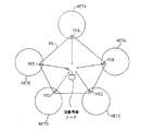
【0031】
図12は、ディスクドライブとしての図11の切換可能装置の説明図である。
【0032】
図12Aは、二つの切換え記憶装置としての図11の切換可能装置の説明図である。
【0033】
図13は、追加の機密保護特徴を有する切換可能な記憶装置としての図7の中間ノードの説明図である。
【0034】
図14は、デュアルポート記憶装置としての図7の中間ノードの説明図である。
【0035】
図15は、プリミティブネットワークのフロントエンドにおけるデータの濾過/修正の説明図である。
【0036】
図16は、二つのプリミティブネットワークを用いて内部ネットワークおよび外部ネットワークを接続する場合の説明図である。
【0037】
図17は、一方向のデータフローを有するプリミティブネットワークの説明図である。
【0038】
図18は、一方向のデータフローを有するプリミティブネットワークの別の説明図である。
【0039】
図19は、図11の切換可能な装置の導通チェックの説明図である。
【0040】
図20は、図11の切換可能な装置の導通チェックの別の説明図である。
【0041】
図21は、切換可能な記憶装置としての本発明の実施例を示すブロック図である。
【0042】
図21Aは、図21の第1の変形例を示すブロック図である。
【0043】
図21Bは、図21の第2の変形例を示すブロック図である。
【0044】
図22Aおよび22Bは、一方向モードにおける受信器ドライバおよび送信器ドライバの動作を示すフロー図である。
【0045】
図23は、図21の記憶装置の一例を示すブロック図である。
【0046】
図24は、図21の論理回路の一例を示すブロック図である。
【0047】
図25は、図21、21Aおよび21Bのスイッチの一例を示すブロック図である。
【0048】
図26は、導通チェックのための回路の図である。
【0049】
図27は、図26の検出器の一例の回路図である。
【0050】
図28は、導通チェックのための別の回路例の図である。
【0051】
<図面の詳細な説明>
図2は、本発明のプリミティブネットワークPNを用いて外部ネットワークNET1(例えばインターネット)に接続された内部ネットワークNET2(例えばLAN)を示す。NET1およびNET2は、共に、各種の既知のおよび(または)標準化された通信プロトコル(その一例はTCP/IPファミリーのプロトコルである)をサポート可能である。本説明の残りの部分については、簡単のため、NET1およびNET2は、共に、 TCP/IPプロトコルを使用する、と仮定するが、NET1およびNET2は、他の種類のプロトコルで運用できること、また、NET1を運用するプロトコルは、NET2を運用するプロトコルと同じでなくてもよいことを理解すべきである。また、説明のため、NET1は、インターネットであり、NET2は、LANであると仮定するが、他の種類のネットワーク構成も普通であり、予想されることを理解すべきである。
【0052】
前述したように、TCP/IPプロトコルは、異なるソフトウェアおよびハードウェア要素間の相互運用が可能となるよう、また、フレキシビリティー、ダイバーシティー、ロバストネスおよび透明性が与えられるよう開発されたため、複雑である。これらプロトコルは、複雑であるため、NET1に接続し得るハッカーは、これらプロトコルを「悪用する」(すなわち、これらプロトコルを操作して、正常な動作を無効にする)方法を発見して、NET2への不法な侵入を成し遂げるかもしれない。図2に示したように、NET1およびNET2のプロトコルのかかる悪用に対抗するため、NET1に接続されたフロントエンドFE1およびNET2に接続された別のフロントエンドFE2を有する第3のネットワーク、すなわち、本発明による保護ネットワークPNを提供する。保護ネットワークPNは、一般に、NET1またはNET2どちらの通信プロトコルとも異なる通信プロトコルを使用する。例えば、SCSI(Small Computer Systems Interface)、SCSI-2、SCSI-3、パラレルデータポート、シリアルデータポートUSB、RS-232、イーザネット(IEEE802.3)、トークンリング(IEEE802.5)、FDDI、ATM、ファイバーチャンネル等、あるいは専用プロトコルが使用可能である。望ましくは、PNに使用されるプロトコルは、できるだけ簡単で「プリミティブ」(複雑でない)であるべきであるが、それは、必要事ではない。例えば、PNがSNA(System Network Architecture)プロトコル(これは複雑なプロトコルである)を使用することは、可能である。必要な全てのことは、プリミティブネットワークが、PN内のいかなる他のノードからも、いかなるフロントエンドも実質的に接収することができないように設計され、かつ(あるいは)、構成されていることである。本説明の残りの部分については、PNは、SCSIプロトコルを使用する、と仮定する。
【0053】
FE1およびFE2は、それぞれ、プリミティブネットワーク上のノード並びに一つまたはそれ以上の隣接ネットワーク上のノードを含んでおり、すなわち、それぞれは、二つのネットワーク上に位置するゲートウェイであり、また、それぞれは、普通に利用できるコンピュータまたは専用機またはハードウェアを含むことができる。ドライバは、プリミティブネットワークにオペラティブアクセスを行う。通信が、FE1からFE2に流れている場合、FE1のコンピュータにおけるドライバの一つの機能は、NET2に送信すべきデータからTCP/IPプロトコルを剥奪して、そのデータをPNに与え、PNのプロトコル(例えばSCSIプロトコル)を用いて送信することである。FE2のドライバの一つの機能は、 SCSIプロトコルを剥奪して、そのデータを与え、(代表的な)TCP/IPプロトコルを用いてエンキャプシュレートし、NET2を越えて宛先に送信することである。図2におけるNET1とNET2の間の通信は、双方向性であることが意図されている以上、FE2におけるコンピュータも、NET1に送信すべきデータからTCP/IPプロトコルを剥奪して、そのデータをSCSIプロトコルのエンベロープに挿入し、また、FE1におけるコンピュータも、そのドライバを用いて、SCSIプロトコルを剥奪し、データをTCP/IPプロトコルにフォーマット化し、NET1を越えて宛先に送信する。
【0054】
図3は、図2の実施例を用いたクライアント‐サーバアプリケーション接続を示し、図4は、図3のクライアント‐サーバ接続のための通信フローの一例である。我々は、説明のため、NET1は、インターネットであり、NET2は、保護されたLANであることを、多くの例の説明で、仮定した。これらは、本発明の説明で使用されるOSI(Open Systems Interconnection)モデルを用いて説明できる。OSIフレームワークにおいては、プロトコルのグループは、層状に配列され、各層は、特定のデータ通信機能を果たす。概念的には、OSIモデルは、最高層がアプリケーション層である層(7層)の縦スタックと見なすことができる。最低層には、物理層(PHY)が有り、これは、ラインを越えてデータを送るためのハードウェアの物理的相互接続特性を指定するものである。これら層の間には、五つの他の層が有り、これらのそれぞれは、ある機能を指定する。これらの層の一つが、ネットワーク層であり、これは、ネットワークを越えたデータパケットの経路指定を行う。
【0055】
図3を参照して、電子コマースWEBに基づくアプリケーションを仮定すると、クライアントは、商人のカタログを漫読し、最後にクライアントブラウザを通して、ある品物を買う。WEBサーバWSは、地理学上、その商人の事務所に存在しているが、実際にはインターネット(NET1)に(恐らく、図示されていない防火壁を通して)接続されており、TCP/IP(インターネットのバックボーンプロトコル)を越えて、HTTP(Hyper Text Transfer Protocol)を介し、インターネット人口全体にアクセス可能である。商人のカタログは、WEBサーバに格納されており、したがって、クライアントは、カタログを漫読し、正規のWEBに基づく技術を用いて、彼の選択を行うことができ、クライアントは、いくつかの高いレベルのトピックを示され、その一つを選択する。クライアントの選択は、ブラウザ(アプリケーションレベル)により、HTTPリクエストにエンコードされ、クライアントのコンピュータのTCP/IPスタックを用いてTCPパケットに変換される。パケットは、その道を、プロトコルスタックを下って物理層まで移動し、そこからある隣接のコンピュータ(恐らくはクライアントのInternet Service Provider(ISP))まで移動する。そのノードにおいて、パケットは、経路指定層(ネットワーク層)にまでしか上がらず、この層により、再び物理層に戻され、この時点でのみ、別のインタフェースを通して、ある他の隣接ノードに移される。パケットは、この道を前進し続けて、WEBサーバノードに達し、そこで、経路指定層は、パケットがその行き先に達したことを検出し、パケットをより高いレベルに渡す。最後に、HTTPリクエストからのデータが、内在するプロトコルから剥奪され、WEBサーバアプリケーションは、(アプリケーション層における)ユーザの選択を受け入れる。WEBサーバは、次いで、適当なカタログ頁を取り込み、フォーマット化されたアイテムを含むHTTPレスポンスを作り上げる。 WEBサーバは、次いで、そのレスポンスを、上述したのと同じやり方で、クライアントのリクエストにより生成されたその同じTCP/IPリンクを越えて、クライアントに送る。クライアントのブラウザは、HTTPエンベロープ(アプリケーション層)を剥奪し、その情報をクライアントの画面に表示する。
【0056】
上記の機構は、クライアントが特定のアイテムを購入する決定を下すまで続く。その特定のアイテムを購入することについての決定は、クライアントの識別ディテールと共に、通常通りフォーマット化されたHTTPリクエストでサーバに転送される。しかしながら、クライアントのアカウントを含むデータベースは、その会社の内部ネットワーク(NET2)に存在し、TCP/IPに基づくプロトコルのいずれかを介して、外部ネットワークに(WEBサーバにすら)アクセスすることはできない。これは、この重要なデータベースおよび他の内部資源が、許されたプロトコルの一つの弱点を利用して内部ネットワークに侵入するハッカーによって悪用されるのを防ぐためである。もちろん、WEBサーバそれ自体は、インターネット上において、未知のクライアントとのTCP/IPセッションに参加することができなければならない。これは、WEBサーバノードを、ハッカーによる乗っ取り企図に対して有り得る標的にすることである。したがって、WEBサーバでも、内部ネットワークを信じるべきではなく、また、インバウンドTCP/IP機能を持つべきではない。
【0057】
WEBサーバは、ひとたび購入注文を受信すると、(アプリケーション層における)その購入注文からデータをフロントエンドの(FE1)ドライバに渡す。フロントエンドドライバは、もし有れば、プリミティブネットワークのプロトコル(プロトコルズ)を用いて、プリミティブネットワークを越えて、この情報を渡す。このデータは、内部ネットワークのフロントエンド(FE2)によって(先ずその物理層によって)拾い上げられ、最後に、ドライバを介して、特定のアプリケーションに渡され、それにより、そのデータが有効なクライアントおよびアイテム情報に対応していることが確認される。データがひとたび確認されると、その特定のアプリケーションは、内部データベースに接触し、標準のプロトコル(例えばTCP/IPを超えるSQLネット)を用いて、クライアントのアカウントを借り方に入れる。パケットは、上記と同じやり方で、クライアントからWEBサーバまで、内部ネットワークを流れる。最後に、その特定のアプリケーションは、肯定応答を返し、肯定応答は、反対方向を流れ流れて、クライアントのブラウザに受信されて表示される。
【0058】
別の実施例においては、WEBサーバは、内部ネットワークに配置される。HTTPリクエスト情報は、プリミティブネットワークを通して、専用のアプリケーションに渡され、専用のアプリケーションは、その有効性を確認する。予め指定されたリストによる特定のリクエストのみが、内部処理を承認される。確認が成功すると、リクエスト情報は、内部WEBサーバに渡され、内部WEBサーバは、リクエストを、それが通常処理するように処理する(必要なら、データベースにアクセスするユーザリトゥンコードを呼び出す)。内部WEBサーバの出力は、次いで、内部ネットワークのフロントエンドに渡され、そこから、プリミティブネットワークを介して、外部ネットワークのフロントエンドに運ばれる。外部WEBサーバは、出力を、処理全体については知らなかったクライアントのブラウザに返す。
【0059】
本発明は、内部ネットワークを外の外部ネットワークに接続する際に生ずるリスクを特定の周知のアプリケーションレベルのリスクに限定することを含む。いかなる他の通信も、承認されたネットワークを除くネットワーク間で渡される(これはリスクを増大する)ことがないのを確認するために、プリミティブネットワーク(もしくは内部ネットワークFE)は、インバウンド通信の全てを暗号化して、適当な対応する暗号解読キーを有する許可された内部サーバのみが、到来データを使用できるようにすることが可能である。さらに、プリミティブネットワーク(もしくは内部ネットワークFE )は、送出通信の全てについて、それらの承認された出所を証明し、かつ、全ての他の送信を阻止する有効なディジタル署名が有るか確認することが可能である。このやり方では、承認された内部処理のみが、プリミティブネットワークPNを通して通信でき、かつ、プリミティブネットワークを通して渡された送信の宛先となることができる。
【0060】
図5は、プリミティブネットワークを越えて、ネットワークNET2に接続されたネットワークNET1を示す。図5に示したプリミティブネットワークは、本質的に、二つのネットワークを接続して、本発明による所望の機密保護分離を与えるのに利用できる幾つかの種類のプリミティブネットワークの一般的な表現である。NET1とNET2の間のプリミティブネットワークPNは、その最も簡単な形態では、データがNET1またはNET2をトラバース中、データをエンキャプシュレートしていたTCP/IPエンベロープからデータがひとたび取り出されると、データが流れる簡単なワイヤ接続にすることができる。一般にハッカーによって利用可能で有り得る TCP/IPプロトコルコードの弱点は、データがひとたびプリミティブネットワークに達すると(そのエンキャプシュレーションから取り出されると)、利用不能となる。
【0061】
図6は、NET1およびNET2を接続するプリミティブネットワークの別の例を示す。この組合せでは、プリミティブネットワークは、NET1およびNET2のフロントエンド間のRS232リンクで構成される。RS232リンクは、TCP/IPエンキャプシュレーションから取り出されたデータを渡す直接接続のような機能を有する。RS232仕様の簡単さは、ハッカーによって利用されて、NET2リンクを越えてNET2に伝播し得るNET1における TCP/IPプロトコルの弱点を許さない。
【0062】
図7は、プリミティブネットワークが、中間ノードを含んでいる好適な実施例である。この中間ノードは、幾つかの形態を取り得る。
【0063】
図8に示した実施例では、中間ノードは、メモリ媒体である。この実施例では、NET1から到来するデータは、このメモリ媒体に書き込まれ、次いで、NET2に接続されたフロントエンドにより読み出される。この方法は、プリミティブネットワークPNによって与えられる分離を可能にするばかりでなく、分離を時間内に可能にする。
【0064】
図9に示したように、プリミティブネットワークの中間ノードにおけるメモリ媒体が、ハードドライブ等の磁気記憶媒体の形態を取る場合には、ディスクの性能は、ディスクへの書込みおよびディスクからの読出しが、ただ一つのセクターに(から)行われれば、改良可能である。この配列では、トラックを捜し、読出しまたは書込みヘッドをデータが書き込まれたトラックの端から端まで移動することに伴う待ち時間が、排除されている。もっと正確に言えば、読出し/書込みヘッド(ヘッズ)は、一個所に留まり、読出しおよび書込み動作は、ただ一つのトラックあるいはセクターで連続的に行われる。
【0065】
さらによりよい性能を出すためには、読出し/書込みブロックを調整して、各サイズに対応させ、磁気媒体に対する読出しおよび書込み動作を不要にすることができる。これは、装置内の部品の移動が減ることになるので、記憶装置の寿命が増大することになる。別法として、動く部品の全くない電子メモリ記憶装置が、使用可能である。
【0066】
図10に示されているように、プリミティブネットワークの中間ノードは、コンピュータそれ自体にすることができる。この場合は、NET1のフロントエンドは、フロントエンドからの情報を中間ノードのコンピュータにロードし、請求に応じて、NET2のフロントエンドに送信されるかあるいはNET2のフロントエンドによって検索されるまで、そこに格納することが可能である。
【0067】
図11においては、プリミティブネットワークの中間ノードは、NET1のフロントエンドに、また、NET2のフロントエンドに選択的に接続できる切換可能な装置として、一般的に示されている。これは、二つのネットワークを常時電子的に切り離された状態に保ち、内部ネットワークFEが、外部FE、すなわち、信頼できないノードの干渉なしに、信頼できる宛先(中間ノード)と常時通信することを保証するものである。
【0068】
図11Aは、切換可能なノード(例えば記憶装置)を有するプリミティブネットワークPNを用いて接続された複数のネットワーク(NETA、NETB、NETC、NETD、NETE)を示す。この図では、NETEのフロントエンドFEEは、切換可能な中間ノードに接続されており、一方、残りの全てのフロントエンド(FEA、FEB、FEC、FED)から切り離されている。次いで、NETEのフロントエンドFEEは、切換可能な中間ノードから切り離され、フロントエンドのうちの別のものが、切換可能な中間ノードに接続され、他のフロントエンドから切り離される。このようにして、一度にただ一つの(ネットワークNETA、NETB、NETC、NETD、NETEの)フロントエンドが、切換可能な中間ノードに接続される。
【0069】
図12においては、切換可能な装置は、ディスクドライブである。NET1のフロントエンドに接続されると、情報は、フロントエンドからディスクに、また、ディスクからフロントエンドに転送可能となる。 NET2のフロントエンドに接続されると、ディスクに格納された情報は、NET2のフロントエンドによって読出し可能となり、また、NET2からの情報は、ディスクに書込み可能となる。望ましくは、ディスクへの、また、ディスクからの転送は全て、直接メモリアクセス(DMA)を用いて行うことができる。
【0070】
図12Aは、切換可能な装置を二つの切換え記憶装置として示すものである。図12に示すように接続された場合は、FE1は、情報を記憶装置1から読み出し、また、記憶装置1に書き込み、一方、FE2は、情報を記憶装置2から読み出し、また、記憶装置2に書き込む。次いで、接続は、切り換えられて、FE1は、記憶装置2に接続され、FE2は、記憶装置1に接続され、それぞれは、他の(書き込まれた)データを読出し可能となり、したがって新しいデータを書込み可能となる。
【0071】
図13は、図12に示した思想の延長で、追加の機密保護機能を有するものを示す。図13の記憶装置は、制御装置、例えば、ハードディスク制御装置を有するハードディスクの制御下で動作する。ハードディスク制御装置は、選択的にリセットされる機能を有する。ディスク制御装置がリセットされると、制御装置メーカによって、あるいはディスクをシステムに組み込むオリジナル・エクイップメント・マニュファクチャラー(OEM)によって予め決められたデフォルト状態にリセットされる。図13に示したリセット位置は、ディスクをNET1のフロントエンドに、また、NET2のフロントエンドに、それぞれ接続するのに利用される二つの状態の間に、ハードディスク制御装置のリセッティングが有るという事実を記号的に示すものである。このリセッティングは、メモリに格納された情報のいずれにも影響を与えない。NET1のフロントエンドが、情報をハードディスクに書き込み、ハードディスクから情報を受け取る場合、ハードディスクは、NET1のフロントエンドに接続され、NET2のフロントエンドから切り離される。ハードディスク接続は、次いで、NET2のフロントエンドに切り換えられ、したがって、情報は、NET2のフロントエンドとハードディスクの間で転送可能となる。NET1またはNET2上のハッカーが、ハードディスクドライブの制御装置に達して制御を取る可能性を防ぐため、制御装置は、スイッチの状態が変わるごとにリセットされる。このやり方では、たとえハッカーが、万一、ハードドライブの制御装置の制御を取っても、ハッカーが故意に改悪した設定は全て、制御装置がリセットされると、消去されてしまう。したがって、制御装置は、その動作に悪意で干渉しようとする外部からの企図とは無関係に、常に正常な状態にあり、また、このようにして機密保護が維持されるのを保証することができる。この方法は、中間ノードとして使用されているいかなるノードにも適用可能であるが、ハードディスクだけには、適用できない。ハードウェアの全ては、メモリの内容がリセットされない限り、リセット可能である。このリセッティングは、中間ノードが、PNプロトコルに適合することを保証する。
【0072】
図11〜13においては、NET1とNET2の間に、物理的または電子的接続が有るいかなる瞬間もない。以下、これがいかにして成し遂げられるかを示す一つの方法を論じる。しかしながら、これは、スイッチの一方の側への接続は、スイッチの次の側への接続が行われる前に、壊されることを保証することだけで成し遂げられる。
【0073】
しかしながら、図14においては、ラインは、両フロントエンドからのデュアル記憶装置(例えばハードディスク)への接続を示すが、NET1のフロントエンドとNET2のフロントエンドの間の信号経路は、信号経路がNET1のフロントエンドとNET2のフロントエンドの間で決して電子的に連続的ではないものである。もっと正確に言えば、この図では、NET1のフロントエンドからの信号経路からのデータは、プリミティブネットワークのハードディスクに書き込まれ、次いで、時間的にずれた点において、NET2のフロントエンドによって磁気媒体から読み出される。この時間的なずれおよび読出し/書込みヘッドの(ハードディスクの)磁気媒体からの物理的分離は、NET1のフロントエンドとNET2のフロントエンドの間の信号経路において、いかなる電気的な接続も行われないことを保証する。
【0074】
データが内部のフロントエンドに到着すると、内部のフロントエンドは、それに渡された情報を検査して、情報をそのままで、あるいは修正して渡す、あるいは完全に阻止するかどうかを決定することが可能となる。明確な決定が自動的にできない場合は、情報は、機密保護オフィサーのコンソールに経路指定して、手動決定することが可能である。内部フロントエンドの機械(もしくは他のデレゲートノード)において行うことができるチェックのいくつかには、ビールスの検出およびディジタル署名の証明(共にインバウンド通信の場合)、およびキーワードの捜索(アウトバウンド通信の場合)等がある。データに対して行われ得る修正の例には、次のもの、すなわち、送出通信の暗号化およびディジタル署名、到来通信の暗号解読、アプリケーションレベルの処理およびフォーマットの変換等がある。
【0075】
内容を濾過する技術が有る場合は、一実施例において述べた本発明の重要な利点は、全ての濾過は、内部(保障された)フロントエンドで行われ、したがって、たとえ外部フロントエンドがハッカーに接収されても、オーバライドできない、という事実である。さらに、全ての暗号キーは、内部(保障された)ネットワーク上で安全に格納され、外部に露出されない。これらのキーは、ハッカーが、外部フロントエンドを越えて制御を取っても検索できない。
【0076】
図15は、データの濾過および修正が、フロントエンドFE1およびFE2の両方で起こり得るという思想を説明するものである。例えば、到来データは、ビールスについて試験でき、かつ(あるいは)FE2で暗号解読できる。しかしながら、時によると、FE1は、内部ネットワークであり、FE2は、外部ネットワークであるため、アウトバウンドで(FE1からFE2に)転送すべきデータは、内部FE、例えば、暗号化、キーワード検出等で、濾過あるいは修正される場合がある。したがって、FE1およびFE2は、共に通信を濾過および修正可能である。FEノードを代表するデレゲートノードは、濾過(および修正)処理を行うことができる。しかしながら、デレゲートノードは、FEと同じネットワーク(すなわち、FE1ではNET1、FE2ではNET2)上に存在する。
【0077】
図16は、二つのプリミティブネットワーク(PN1、PN2)を用いて、NET1と NET2の間で追加の機密保護を行うネットワークアーキテクチャを示す。前述の例のうちの多くのものにおいては、NET2は、安全であると仮定し、一方、NET1、すなわち、一般にインターネットは、明らかに安全ではない。しかしながら、NET2も安全ではあり得ないことは、珍しくはない。そのような状況においては、内部ネットワークを両方のネットワーク上でユーザから保護するのが望ましい場合がある。これを行う一つの方法は、図16のアーキテクチャに示されている。NET1のフロントエンドは、PN1を越えて中間ノードに接続されている。中間ノードからの情報の流れは、次いで、PN2を越えて、NET2に渡すことができる。この様式においては、データを濾過する中間ノードは、両方のネットワークから保護され、内部ネットワーク(NET2)に駐在するハッカーでも、そのノードで行われる機密保護濾過をオーバライドすることはできない。
【0078】
データが一方向にのみ流れることが保証されることが望まれる場合もある。そのような状況は、データを、一つのネットワークから一方向にのみ送信したい場合、および情報を送信しつつある相手の他のネットワークといかなる相互作用も起こるべきではない場合に、生じ得る。図17は、これを行うための一つの方法を示す。図17においては、RS232リンクは、データが一方向にのみ流れるように仕切られている。具体的には、反対方向のリンクは、RS232コネクタに配線を装備しないことによって、あるいはスイッチを投入することによって不能にする。
【0079】
図18には、記憶装置が、例えば、ハードディスクである異なる実施例が示してある。図18においては、情報の一方向の流れは、スイッチを一方のフロントエンドへの接続から他方のフロントエンドへの接続に切り換えた時、ハードディスクに書込み保護モードを加えることによって成し遂げられる。図17に示すように、ハードディスク(記憶装置)が、NET2のフロントエンドに接続されると、書込み保護ラインが起動し、NET2のフロントエンドからの情報は、ハードディスクに書き込みできなくなる。情報は、NET1のフロントエンドからしかハードディスクに書き込みできなくなり、したがって、情報は、NET1からNET2への方向でしか流れることができなくなる(NET2が内部ネットワークである例では、この構成によれば、(機密性が高い)内部ネットワークからのどんな情報でも漏れないことが保証される)。機密安全性が増大した場合は、記憶装置のデフォルトモードは、読出し専用モードであり、制御信号に応答する場合のみ、読出し/書込みモードに変わる。
【0080】
図19は、切り換えられた装置の入力と出力の間の導通(すなわち短絡)をチェックすることによって、NET1のフロントエンドとNET2のフロントエンドの間の信号経路において、いかなる電気的接続も行われないことを保証するという思想を示す。
【0081】
図20は、切り換えられた経路両端の間の導通をチェックする実施例を示す。特に、周期波(例えば、正弦波)が、バス接続の一方の側で全ての信号線に注入され、バス接続の他方の側は、注入された周期波が、その信号線のいずれにも存在するかどうか判定する。周期波の存在は、切り換えられた経路両端の間の導通を示す。
【0082】
図21は、本発明の実施例を示すブロック図であり、二つのネットワークのフロントエンドとして働く二つのコンピュータ(COMP AおよびCOMP B)、および切換可能な記憶装置を含む。コンピュータAは、SCSIバス20を介してSCSIスイッチ200に接続されており、コンピュータBは、SCSIバス30を介してスイッチ200に接続されている。SCSIバス20および30両方からのバス信号は、バス信号50として、ロジック400に与えられ、これは、コントロール60をスイッチ200に与える。スイッチ200は、記憶装置300にも接続されており、これは、例えば、別のSCSIバス400を介した、磁気ディスクまたは電子メモリ装置であり得る。本説明においては、スイッチ200は、記憶装置300をSCSIバス30またはSCSIバス20のどちらかに接続するアナログ切換装置(後述)として実施されている。しかしながら、スイッチ200の他の実施例も可能である。スイッチ200のトグリングを制御する信号は、記憶装置300に現在接続されているコンピュータに存在するドライバに源を発し、好適な一実施例においては、各コンピュータによる、ディスクにアクセスして完了する指示であり得る。この指示は、ロジック400に与えられ、これは、コントロール60を発行して、スイッチ200に命令し、記憶装置への接続を一方のSCSIバスから他方のSCSIバスに切り換える。フロントエンドにより送られた信号は、別の実施例においては、非存在装置への書き込み指令であり得る。
【0083】
ロジック400はまた、記憶装置300に書込み可信号を与え、記憶装置300を読出し/書込みモードまたは読出し専用モードのどちらかにする選択を可能にする。本発明のユーザは、これらのモードが選択できる。例えば、記憶装置300のモードは、コンピュータAに接続する場合、読出し専用モードに、また、スイッチ200が、コンピュータBをそれに接続する場合、読出し/書込みモードに選択可能である。したがって、いかなるデータも、コンピュータAで表されるネットワークからコンピュータBで表されるネットワークに、プリミティブネットワークを通して流れることはできない。前述のように、機密保護の目的のため、記憶装置300のデフォルトモードは、読出し専用モードである。これは、ロジック400が、当該FEがデータを渡すことを実際に可能にしていることを保証するものである。
【0084】
記憶装置300が、例えば、コンピュータAに接続されて、読出し専用モード(一方向モード)に設定される場合は、データの読出しが成功して、データが処理されたことを示すいかなる肯定応答も記憶装置に書き込むことはできない。
【0085】
図22Aおよび22Bは、読出し専用モード(一方向モード)における受信器ドライバおよび送信器ドライバのこの問題と取り組むための動作を示すフローダイヤグラムである。図22Aを参照すると、(データの)受信器は、先ず、記憶装置300が、取り付けられているかどうかを判定し、取り付けられていない場合は、取り付けられるまで待機する。記憶装置300が、取り付けられている場合は、記憶装置の内容は、読み出され、確認される。次いで、内容が、(恐らくは、それをその最終の宛先に送って処理することによって)処理される。処理が成功裡に完了した場合は、スイッチ200が接続を切り換えるべきことを示す「トグル」信号が送られる。データの処理が成功しなかった場合は、内部コンテキストは、リセットされ、次いで、(遅延後)「トグル」信号が送られる。遅延は、送信器により、負の肯定応答として解釈される。
【0086】
図22Bを参照すると、送信器は、記憶装置に送られるべき情報の小さなチャンクを用意し、次いで、記憶装置300が取り付けられているかどうかを問い合わせる。答えがNOの場合は、情報の準備は、記憶装置300が取り付けられるまで継続する。記憶装置300が取り付けられている場合(YESの場合)は、タイマーからの時間が、≧δ(図22Aの遅延時間)であり、かつ(あるいは)、最初の時間ではないかどうかについて、問い合わせが行われる。応答がNOの場合は、処理された情報のブロックは、記憶装置に書き込まれ、タイマーが起動し、「トグル」信号が発行される。
【0087】
しかしながら、応答がYESの場合は、次いで、内部コンテキストがリセットされ(送られる次のブロックが送信の開始を表すことを意味する)、データのブロックが記憶装置に書き込まれ、タイマーが、再起動し、「トグル」信号が初期化される。したがって、もし受信器が記憶装置300を遅延時間(δ秒)保持している場合は、送信器は、タイマーの時間がδより長い(これは情報を再送信すべきことを示す)、と判定する。遅延時間δは、不必要なリセットを避けるため、通常のサイクルタイムより相当長く取るべきである。
【0088】
図21Aは、図21の変形例で、記憶装置300を解放する信号が、FE1およびFE2からの特殊指令により、スイッチ200とSCSIバス40のスイッチ接続を介して、記憶装置300に送られる。記憶装置300は、次いで、制御信号をロジック400に発行し、これは、コントロール60を発行して、スイッチ200に命令し、接続を一方のSCSIバスから他方のSCSIバスに切り換える。
【0089】
図21Bは、図21のさらに別の変形例を示し、記憶装置300を解放する信号が、フロントエンドから直接ロジック400に送られる。ロジック400は、次いで、コントロール60を発行して、スイッチ200に命令し、接続を一方のSCSIバスから他方のSCSIバスに切り換える。
【0090】
図23は、図21の記憶装置300を示すブロック図である。データは、制御装置310により、SCSIバス40から受信される。SCSIターミネータ350は、SCSIバスの適切な成端を保証する。制御装置310はまた、マイクロプロセッサ320にも接続されており、これは、コントロール、アドレスおよびデータ信号を制御装置310に与える。補助バスが、マイクロプロセッサを、CPLD330(Complex Programmable Logic Device)に接続し、これは、制御信号およびDMA(Direct Memory Access)アドレスをメモリ340に与える。DMA制御信号はまた、制御装置310とCPLD330の間で双方向的に与えられる。メモリ340に格納すべきデータは、DMAデータバスを越えて与えられる。ロジック400からの書込み可信号(メモリ340を読出し/書込みモードあるいは読出し専用モードにするのに使用される)は、CPLD330に与えられ、メモリ340への制御信号の一部を形成する。上述のように、メモリ340のデフォルトモードは、読出し専用モードである。
【0091】
図24は、図21のロジック400を示すブロック図である。ロジック400には、 Complex Programmable Logic Device(CPLD)440が含まれており、これは、フロントパネル(図示せず)の構成要素を駆動するのに、また、制御信号60および書込み可信号を与えるのに使用される。CPLDはまた、上記の非存在装置への企図された接続を検出するのにも使われる。また、バス50で受信された生のバス信号から必要なディジタル信号を与えるためのアナログ処理回路450、導通チェック回路410、注入器発生器430および導通チェック回路410と注入器発生器430の同期を取るためのクロック420が含まれている。注入器発生器430からの信号は、制御信号60を与えられる。導通チェック回路410と注入器発生器430(後で詳述)は、上述の接続の導通をチェックするのに使用される。
【0092】
図25は、図21のスイッチ200の説明図である。スイッチ200は、一方の側に二つのSCSIポート(一つはCOMP Aのラベル付き、他はCOMP Bのラベル付き)および他方の側に二つのSCSIポート(一つはTERMのラベル付き、他はDISKのラベル付き)を有している。スイッチ200は、COMP AをDISKに、かつ、COMP BをTERMに、あるいはCOMP AをTERMに、かつ、COMP BをDISKに、接続可能である。どちらの場合にも、これは、両SCSIバスに対して透明である。本発明の一実施例においては、DISKは、終端されたSCSI記憶装置に接続されており、TERMは、SCSIターミネータに接続されている。さらなる性能を求める場合には、TERMは、第2の終端されたSCSI記憶装置に接続可能である。この方式においては、各FEは、常時それ自体に取り付けられているが、フロントエンドを依然として切り離している記憶装置を有している。三つの同じチップ210A、210Bおよび210C(それぞれ12組のアナログスイッチを有している)は、図25において実際の切換を行う。チップは、3個示してあるが、ただ1個のアナログチップまたは3個以上のチップを使用することが可能である。必要な切換機能を果たす何か他の種類のスイッチ(例えばリレー)を使用することも可能である。
【0093】
注入器発生器430から与えられた信号は、注入器220(後で詳述)に入力されて、コンピュータBからのラインに信号を注入する。この図の場合には、検出器(図26および27参照)が、コンピュータAのラインに設けられている。図25は、コンピュータBからのラインにおける信号の注入を示すが、これは、逆にすることもでき、すなわち、検出器をコンピュータBからのラインに接続して、コンピュータAからのラインに信号を注入することもできる。
【0094】
図26は、発生器430、クロック420、および注入器220および導通チェック回路410(これらは導通チェックに使用する)の代表的な接続を示す図である。クロック420からのCLK信号は、注入器発生器回路430および導通チェック回路410の両方に与えられる。CLK信号は、ジッター回路291に入力され、これは、注入器発生器の同期を保ち、ジッター回路291の出力は、分圧器を通してNPNトランジスタ292のベースに与えられるが、これは、ベースが直列に接続された抵抗器293と295の間のノードに接続されているためである。これは、注入器と併用されて、温度が変動した場合のトランジスタの挙動の変化を補償する。VCCは、抵抗器295の別の端に、また、トランジスタ292のコレクタに与えられる。トランジスタ292のエミッタは、出力ノードに接続されており、これはまた、抵抗器297を通して大地に接続されている。したがって、トランジスタ292の出力ノードに接続される信号は、振動電圧であり、これは、注入器220の各注入器のベースに与えられる。各注入器のSCSIバスAは、抵抗器294(例えば294A から294Nまで)を通して、VCCに接続されたトランジスタ296(例えば296A から296Nまで)で形成されている。図の注入器のそれぞれは、電流源であり、各トランジスタ296のベースにおける信号は、特定の線(バスの線)に注入される電流の量を決定する。結果として、各トランジスタ294のベースに与えられる同じ信号が、各線(バスの線)に注入される。SCSIバスBには、導通チェック回路410が接続されており、これは、バスの各信号線用の検出器298(例えば298A から298Nまで)を有している。
【0095】
図27は、代表検出器298の回路図である。各検出器は、バスラインから参照信号CLKおよび検出器信号INを受信し、参照信号CLKの周波数と同じ周波数をIN信号に求める。参照信号CLKは、周波数検出器(またはTone Detector、またはPhase Lock Loop(PLL))に与えられ、これは、一実施例では、National Semiconductor製のLM567であり、これもIN信号を受信する。図27に示したコンデンサおよび抵抗器は、LM567の代表的な構成で使用されているものである。LM567が、検出器IN信号中に参照周波数CLKを見出すと、OUT信号がローになり、見出さない場合は、 OUT信号は、ハイである。したがって、短絡(スイッチ両端の間の回路導通)がある場合は、検出器の出力は、ローであり、短絡がない(回路導通がない)場合は、検出器の出力は、浮動している(コレクタオープン)。
【0096】
SCSIバスは、導通検出に用いられる周波数よりも高い周波数で動作するので、検出周波数も含むことができる。したがって、偽アラームを防ぐ必要がある。これを行う一つの方法は、バスワイヤが空いている時のみ、注入された信号をチェックすることである。SCSIでは、これは、電圧がハイ(ロジカルFALSE)であることを意味する。
【0097】
トランジスタ610、抵抗器612および614は、IN信号が、ロジカル真(0 V)レベルである時には何時でも、そしてその後間もなく検出を不可にするよう設けられている。IN信号は、抵抗器612を通して、PNPトランジスタ610のベースに与えられる。トランジスタ610のコレクタは、ノード620に接続されており、これはまた、検出器OUTに、抵抗器614(LM567の出力に接続されている)に、そしてコンデンサ618の一端にも接続されている。コンデンサ618の他端は、大地に接続されている。この接続では、IN信号がローの時には何時でも、PNPトランジスタ610は、ONであり、コンデンサ618は、充電されており、したがって、検出器信号OUTは、ハイである、すなわち、いかなる短絡も検出されない。IN信号がハイである時は、トランジスタ610は、オフであり、LM567が、IN周波数と参照CLK周波数の一致を発見した場合は、OUTPUT信号は、ローになる。したがって、コンデンサ618は、充電し、検出器のOUT信号は、ローになり、短絡(回路導通)を示すことになる。
【0098】
図28は、図26に示した接続の別の接続例の回路図であり、発生器430’、注入器220’および導通チェック回路410’が、導通チェックで用いられる。各注入器296’は、図26に示した注入器296と同様であるが、発生器430の代わりに、定電圧発生器430’によって与えられる、PNPトランジスタ710のベースに加えられる定電圧を有する点が異なる。したがって、バスの各線には、定電流が加えられる。各検出器は、電圧比較器712(712A〜712N)であり、回路導通がある場合は、比較器712への入力は、Vrefよりも大きく、出力は、「1」になり、短絡があることを示すことになる。図28に示したように、検出器712A〜712Nの出力は、NOTゲート760への入力である。
【0099】
上記の説明において、本発明はその特定の実施例を参照して説明した。しかしながら、それらには、本発明のより広い精神および範囲から逸脱することなく、様々な修正および変更を加えることが可能であるのは、明らかである。例えば、本発明は、二つのネットワークの間の連係を示すことによって説明したが、説明した技術は、三つまたはそれ以上のネットワークのネットワーク相互接続に、ルーチン方式で応用可能であろう。[0001]
The present invention is entitled “Offline Firewall”, provisional
[0002]
<Technical field>
The present invention relates to a technique for providing security protection in a data communication network. More specifically, the present invention is directed to a technique that provides protected connectivity between different networks to prevent intruders from exploiting the weaknesses of network protocols (protocols).
[0003]
<Background of the invention>
Currently, the general public is increasingly using the Internet as a source of information and for communication. Therefore, in many networks (which otherwise requires maintaining a high level of security), sharing or disclosing limited data / resources or their It is necessary to populate the data from unbelievable parties without making “holes” in sensitive resources. For example, in an e-commerce application, a company that maintains an “Internet store” wants to disclose the “Internet store” but does not intend to endanger the company's internal accounting database by doing so. It will be clear. In another example, a telecommunications company wants to supply its customers with an online monthly statement, but does not risk "hackers" entering the company's telecommunications switch through this online connection. Will. In yet another example, a classified military base would like to import weather forecast information, but would not run the risk of sensitive information leaking out.
[0004]
Today's methods of connecting networks utilize technology developed for general connectivity. These technologies consist of complex communication protocols that have been developed to allow interoperability between different software and hardware elements and provide flexibility, diversity, robustness and transparency. An important example of such a protocol is TCP / IP (Transmission Control Protocol / Internet Protocol). Other examples of protocols are DECnet, SNA, and Novell. Security was not an important issue when developing technology for general consolidation. Furthermore, security and robustness are inherently incompatible with each other at least in part. More specifically, the higher the level of system complexity, the greater the risk that the system will contain some degree of barrelability when attacked by hackers.
[0005]
In order to tackle the security flaws in common connection methods, firewalls have been introduced that are typically implemented with complex software. A firewall is typically located at a network node that monitors all communications entering the network from an external source, such as another network. FIG. 1 shows an example of a firewall (FW) used to connect the internal network NET2 to the external network NET1. In this example, the external network NET1 is a WAN (Wide Area Network) such as the Internet, and NET2 is a LAN (Local Area Network). However, the principle of the present invention is generally applied to networks.
[0006]
An important purpose of the firewall FW is to prevent communication from NET1 suspected of hostility. However, this is a splice to the problem and not a true solution. The reason is as follows.
[0007]
1. The firewall is a node of the internal network NET2. That is, the firewall is vulnerable to attacks by hackers on its operating system, protocol or application. Once the firewall is confiscated, the entire function of the firewall can be overridden and disabled by the hacker. Because the firewall is the last line of defense against intrusion into the network, when the firewall breaks, the internal network is exposed.
[0008]
2. The firewall will be transparent to the application and will attempt to be flexible enough for all possible configurations of the NET2 organization. Firewalls also rely entirely on humans to configure firewalls to separate “good” and “bad” communications. As the needs of organizations using NET2 change constantly, the firewall software configuration is constantly changing to meet the changing needs. As a result of frequent changes, the likelihood of mistakes that can compromise the security of the network increases.
[0009]
3. The firewall itself must be a complex system to “understand” the communications that pass through it. That is, the firewall may contain software bugs that can be used by hackers, design defects, or cases that have never been handled. Additionally, it may not be possible to determine whether communication is valid without accessing a wider context where the firewall may not be available.
[0010]
4). Firewalls are generally allowed to pass all kinds of management and internal protocols in order to be compatible with regular and transparent connections. Clients are often unaware of this and may risk using a firewall without taking this into account. For example, when importing a file into a network, firewalls generally prevent FTP (File Transfer Protocol), TCP, DNS (Domain Nature System), ICMP (Internet Control Message Protocol) and other control messages from passing. Must be configured to forgive.
[0011]
Therefore, there is a need for new technologies that are built from the ground up with security in mind and that provide a very specific and important type of connection between internal and external networks.
[0012]
<Summary of invention>
The term “network” is used in the present invention as a group of nodes (eg, computers, storage devices, printers, etc.) connected together using physical and electronic interconnections, in which case all Each node is connected to at least one other node, either directly or through an intermediate link and / or device, in accordance with certain pre-agreed rules, commonly referred to as “protocols”. A participating node in the network may transfer information to other nodes in the network by conforming to the network protocol. The connection between the source and target typically passes through other participating nodes in the network that route information to its destination.
[0013]
One aspect of the present invention involves separating the internal network from the external network. Ideally, for security reasons, the two networks should be separated. In fact, without some transport, the selected information cannot be carried between networks. In order to minimize the risk of security, this transport should be as simple as possible and as simple or “primitive”. Accordingly, the present invention introduces the idea of a “primitive network” that is a “barrier” between an internal network and an external network.
[0014]
"Primitive network" should be understood to mean a network consisting of front-end nodes and optionally intermediate nodes. The front-end node may include one or more computers or dedicated hardware. Primitive networks (in conjunction with their associated protocols, and physical and electronic connections) allow one front-end node to transfer information to some other front-end node (hereinafter abbreviated as front-end or FE) It is equipped with the mechanism. An optional intermediate node can be used to help secure or flow information from one front end to another.
[0015]
In some embodiments of the present invention, the primitive network has no electrical connection between the inside and outside of the protected network at any given time, i.e., the inside and outside are mutually exclusive from each other. Follow the rule of being electrically separated.
[0016]
An important feature of a primitive network barrier is that it “breaks” all layers of the protocol on both sides (ie internal and external networks), while selective data carried by those protocols is passed. Is to forgive. Primitive networks do not support the full protocol stack used in internal and external networks, but may support completely different protocols.
[0017]
Various advantages and features of the present invention will become more readily apparent to those skilled in the art from the following description of the invention, particularly when used in conjunction with the accompanying drawings.
[0018]
<Brief description of drawings>
When referring to the accompanying drawings, it should be noted that elements having the same reference numerals represent similar elements in all the drawings.
[0019]
FIG. 1 is an explanatory diagram of an internal network connected to an external network using a firewall.
[0020]
FIG. 2 is an explanatory diagram of an internal network connected to an external network by a primitive network according to the present invention.
[0021]
FIG. 3 is an explanatory diagram of the client-server application connection of FIG.
[0022]
FIG. 4 is an example of the client-server application communication flow of FIG.
[0023]
FIG. 5 is an illustration of protocol differences between internal and external network protocols and primitive networks.
[0024]
FIG. 6 is an explanatory diagram of a primitive network based on the RS232 protocol.
[0025]
FIG. 7 is an explanatory diagram of a primitive network including intermediate nodes.
[0026]
FIG. 8 is an explanatory diagram of the intermediate node of FIG. 7 as a memory medium.
[0027]
FIG. 9 is an explanatory diagram of the intermediate node of FIG. 7 as a magnetic storage medium.
[0028]
FIG. 10 is an explanatory diagram of the intermediate node of FIG. 7 as a computer.
[0029]
FIG. 11 is an explanatory diagram of the intermediate node of FIG. 7 as a switchable device.
[0030]
FIG. 11A is an explanatory diagram when a plurality of networks connected together with a primitive network have switchable intermediate nodes.
[0031]
FIG. 12 is an explanatory diagram of the switchable device of FIG. 11 as a disk drive.
[0032]
FIG. 12A is an explanatory diagram of the switchable device of FIG. 11 as two switching storage devices.
[0033]
FIG. 13 is an illustration of the intermediate node of FIG. 7 as a switchable storage device with additional security features.
[0034]
FIG. 14 is an explanatory diagram of the intermediate node of FIG. 7 as a dual port storage device.
[0035]
FIG. 15 is an explanatory diagram of data filtering / correction at the front end of the primitive network.
[0036]
FIG. 16 is an explanatory diagram for connecting an internal network and an external network using two primitive networks.
[0037]
FIG. 17 is an explanatory diagram of a primitive network having a one-way data flow.
[0038]
FIG. 18 is another explanatory diagram of a primitive network having a one-way data flow.
[0039]
FIG. 19 is an explanatory diagram of the continuity check of the switchable device of FIG.
[0040]
FIG. 20 is another explanatory diagram of the continuity check of the switchable device of FIG.
[0041]
FIG. 21 is a block diagram showing an embodiment of the present invention as a switchable storage device.
[0042]
FIG. 21A is a block diagram showing a first modification of FIG.
[0043]
FIG. 21B is a block diagram showing a second modification of FIG.
[0044]
22A and 22B are flow diagrams illustrating the operation of the receiver driver and transmitter driver in one-way mode.
[0045]
FIG. 23 is a block diagram illustrating an example of the storage device of FIG.
[0046]
FIG. 24 is a block diagram illustrating an example of the logic circuit of FIG.
[0047]
FIG. 25 is a block diagram illustrating an example of the switches of FIGS. 21, 21A, and 21B.
[0048]
FIG. 26 is a diagram of a circuit for checking continuity.
[0049]
FIG. 27 is a circuit diagram of an example of the detector of FIG.
[0050]
FIG. 28 is a diagram of another circuit example for continuity check.
[0051]
<Detailed description of the drawings>
FIG. 2 shows an internal network NET2 (eg LAN) connected to an external network NET1 (eg Internet) using the primitive network PN of the present invention. Both NET1 and NET2 can support a variety of known and / or standardized communication protocols, an example of which is the TCP / IP family of protocols. For the remainder of this description, for the sake of simplicity, it is assumed that both NET1 and NET2 use the TCP / IP protocol, but NET1 and NET2 can operate with other types of protocols, and NET1 It should be understood that the protocol that operates is not necessarily the same as the protocol that operates NET2. Also, for purposes of explanation, it is assumed that NET1 is the Internet and NET2 is a LAN, but it should be understood that other types of network configurations are common and expected.
[0052]
As previously mentioned, the TCP / IP protocol is complex because it was developed to allow interoperability between different software and hardware elements, and to provide flexibility, diversity, robustness and transparency. is there. Because these protocols are complex, hackers who can connect to NET1 have discovered ways to “exploit” these protocols (ie, manipulate these protocols to disable normal operation) and get to NET2. May have achieved an illegal intrusion. As shown in FIG. 2, a third network with a front end FE1 connected to NET1 and another front end FE2 connected to NET2 to counter such misuse of the NET1 and NET2 protocols, ie, this book A protection network PN according to the invention is provided. The protection network PN generally uses a communication protocol that is different from either the NET1 or NET2 communication protocol. For example, SCSI (Small Computer Systems Interface), SCSI-2, SCSI-3, parallel data port, serial data port USB, RS-232, Ethernet (IEEE802.3), token ring (IEEE802.5), FDDI, ATM Fiber Channel, etc., or a dedicated protocol can be used. Desirably, the protocol used for PN should be as simple and “primitive” (uncomplicated) as possible, but it is not necessary. For example, it is possible for the PN to use the SNA (System Network Architecture) protocol (which is a complex protocol). All that is required is that the primitive network is designed and / or configured such that virtually no front end can be seized from any other node in the PN. . For the remainder of this description, it is assumed that PN uses the SCSI protocol.
[0053]
FE1 and FE2 each include a node on the primitive network and one or more nodes on the neighboring network, ie, each is a gateway located on two networks, and each It can include commonly available computers or special purpose machines or hardware. The driver performs operative access to the primitive network. If communication is flowing from FE1 to FE2, one function of the driver in the FE1 computer strips the TCP / IP protocol from the data to be sent to NET2, gives that data to the PN, For example, the transmission is performed using the SCSI protocol. One function of the FE2 driver is to strip the SCSI protocol, provide the data, encapsulate it using the (typical) TCP / IP protocol, and send it to the destination over NET2. . Because the communication between NET1 and NET2 in Figure 2 is intended to be bidirectional, the computer in FE2 also strips the TCP / IP protocol from the data to be sent to NET1 and passes the data to SCSI. The computer in FE1 also uses the driver to strip the SCSI protocol, format the data into the TCP / IP protocol, and send it to the destination over NET1.
[0054]
FIG. 3 shows a client-server application connection using the embodiment of FIG. 2, and FIG. 4 is an example of a communication flow for the client-server connection of FIG. For the purposes of explanation, we have assumed in many example descriptions that NET1 is the Internet and NET2 is a protected LAN. These can be described using an OSI (Open Systems Interconnection) model used in the description of the present invention. In the OSI framework, groups of protocols are arranged in layers, with each layer performing a specific data communication function. Conceptually, the OSI model can be viewed as a vertical stack of layers (7 layers) where the highest layer is the application layer. At the lowest layer is the physical layer (PHY), which specifies the physical interconnection characteristics of the hardware for sending data across the line. Between these layers are five other layers, each of which specifies a function. One of these layers is the network layer, which routes data packets across the network.
[0055]
Referring to FIG. 3, assuming an application based on e-commerce WEB, the client browses the merchant's catalog and finally buys an item through the client browser. The WEB server WS exists geographically at the merchant's office, but is actually connected to the Internet (NET1) (possibly through a firewall not shown) and TCP / IP (Internet The entire Internet population can be accessed over HTTP (Hyper Text Transfer Protocol). The merchant's catalog is stored on the WEB server, so the client can browse the catalog and make his choices using legitimate WEB-based technology, the client has several high levels Select one of the topics shown. The client selection is encoded into an HTTP request by the browser (application level) and converted into a TCP packet using the TCP / IP stack of the client computer. The packet travels the way down the protocol stack to the physical layer and from there to an adjacent computer (possibly the client's Internet Service Provider (ISP)). At that node, the packet only goes up to the routing layer (network layer), which returns it back to the physical layer, and only at this point is it moved through some other interface to some other neighboring node. The packet continues to advance this way and reaches the WEB server node, where the routing layer detects that the packet has reached its destination and passes the packet to a higher level. Finally, the data from the HTTP request is stripped from the underlying protocol and the web server application accepts the user's choice (at the application layer). The web server then takes the appropriate catalog page and creates an HTTP response containing the formatted item. The WEB server then sends the response to the client over the same TCP / IP link created by the client request in the same manner as described above. The client browser strips the HTTP envelope (application layer) and displays the information on the client screen.
[0056]
The above mechanism continues until the client makes a decision to purchase a particular item. The decision to purchase that particular item is forwarded to the server in a normally formatted HTTP request, along with the client's identification details. However, the database containing the client's account exists on the company's internal network (NET2) and cannot access the external network (even the web server) via any of the TCP / IP based protocols. This is to prevent this critical database and other internal resources from being exploited by hackers who use one weakness of the allowed protocols to penetrate the internal network. Of course, the WEB server itself must be able to participate in TCP / IP sessions with unknown clients on the Internet. This is to make the WEB server node a possible target for hijacking attempts by hackers. Therefore, WEB servers should not trust the internal network and should not have inbound TCP / IP functions.
[0057]
Once the WEB server receives the purchase order, it passes data from the purchase order (in the application layer) to the front end (FE1) driver. The front-end driver passes this information across the primitive network, if any, using the primitive network protocol (protocols). This data is picked up by the internal network front end (FE2) (first by its physical layer) and finally passed through the driver to the specific application, so that the data is valid client and item information It is confirmed that Once the data is verified, that particular application contacts an internal database and debits the client's account using standard protocols (eg, SQL Net over TCP / IP). Packets flow through the internal network from the client to the web server in the same manner as above. Finally, that particular application returns an acknowledgment, which flows in the opposite direction and is received and displayed by the client browser.
[0058]
In another embodiment, the WEB server is located on the internal network. The HTTP request information is passed to the dedicated application through the primitive network, and the dedicated application confirms the validity. Only certain requests from a pre-specified list are approved for internal processing. If the verification is successful, the request information is passed to the internal WEB server, which processes the request as it normally processes (calls a user return code that accesses the database if necessary). The output of the internal WEB server is then passed to the front end of the internal network, from which it is carried via the primitive network to the front end of the external network. The external web server returns the output to the client browser that did not know about the entire process.
[0059]
The present invention includes limiting the risks that arise when connecting an internal network to an external network outside to certain well-known application level risks. In order to ensure that no other communication is passed between networks except authorized networks (which increases the risk), the primitive network (or internal network FE) is responsible for all inbound communication. It can be encrypted so that only authorized internal servers with the appropriate corresponding decryption key can use the incoming data. In addition, the primitive network (or internal network FE) can verify their authorized origin for all outgoing communications and verify that there is a valid digital signature that blocks all other transmissions. It is. In this manner, only approved internal processing can communicate through the primitive network PN and can be the destination for transmissions passed through the primitive network.
[0060]
FIG. 5 shows network NET1 connected to network NET2 over the primitive network. The primitive network shown in FIG. 5 is essentially a general representation of several types of primitive networks that can be used to connect two networks to provide the desired security separation according to the present invention. In its simplest form, the primitive network PN between NET1 and NET2 is traversing NET1 or NET2, and once the data is retrieved from the TCP / IP envelope that was encapsulating the data, It can be a simple wire connection that flows. A weakness in the TCP / IP protocol code that can generally be used by hackers becomes unavailable once the data reaches the primitive network (removed from its encapsulation).
[0061]
FIG. 6 shows another example of a primitive network connecting NET1 and NET2. In this combination, the primitive network consists of RS232 links between the NET1 and NET2 front ends. The RS232 link has a function like a direct connection for passing data extracted from TCP / IP encapsulation. The simplicity of the RS232 specification does not allow the weakness of the TCP / IP protocol in NET1 that can be exploited by hackers and propagated over NET2 links to NET2.
[0062]
FIG. 7 is a preferred embodiment in which the primitive network includes intermediate nodes. This intermediate node can take several forms.
[0063]
In the embodiment shown in FIG. 8, the intermediate node is a memory medium. In this embodiment, data coming from NET1 is written to this memory medium and then read by the front end connected to NET2. This method not only allows the separation provided by the primitive network PN, but also allows the separation in time.
[0064]
As shown in FIG. 9, when the memory medium in the intermediate node of the primitive network takes the form of a magnetic storage medium such as a hard drive, the performance of the disk is only written to the disk and read from the disk. If done in one sector, it can be improved. In this arrangement, the latency associated with searching for the track and moving the read or write head from end to end of the track on which the data was written is eliminated. More precisely, the read / write head (heads) remains in one place, and read and write operations are performed continuously on only one track or sector.
[0065]
For even better performance, the read / write block can be adjusted to accommodate each size, eliminating the need for read and write operations on the magnetic media. This will increase the life of the storage device because the movement of parts in the device will be reduced. Alternatively, an electronic memory storage device with no moving parts can be used.
[0066]
As shown in FIG. 10, the intermediate node of the primitive network can be the computer itself. In this case, the NET1 front-end loads the information from the front-end into the intermediate node's computer and sends it to the NET2 front-end until requested or retrieved by the NET2 front-end, upon request. Can be stored.
[0067]
In FIG. 11, the intermediate nodes of the primitive network are generally shown as switchable devices that can be selectively connected to the front end of NET1 and to the front end of NET2. This keeps the two networks electronically disconnected at all times and ensures that the internal network FE always communicates with the trusted destination (intermediate node) without interference from the external FE, ie untrusted nodes. To do.
[0068]
FIG. 11A shows a plurality of networks (NETA, NETB, NETC, NETD, NETE) connected using a primitive network PN having switchable nodes (for example, storage devices). In this figure, the NETE front end FEE is connected to a switchable intermediate node, while being disconnected from all remaining front ends (FEA, FEB, FEC, FED). The NETE front end FEE is then disconnected from the switchable intermediate node, and another of the front ends is connected to the switchable intermediate node and disconnected from the other front ends. In this way, only one front end (of networks NETA, NETB, NETC, NETD, NETE) is connected to the switchable intermediate node at a time.
[0069]
In FIG. 12, the switchable device is a disk drive. When connected to the NET1 front end, information can be transferred from the front end to the disk and from the disk to the front end. When connected to the NET2 front end, information stored on the disk can be read by the NET2 front end, and information from NET2 can be written to the disk. Preferably, all transfers to and from the disk can be done using direct memory access (DMA).
[0070]
FIG. 12A shows a switchable device as two switching storage devices. When connected as shown in FIG. 12, FE1 reads information from the storage device 1 and writes it to the storage device 1, while FE2 reads information from the storage device 2 and also stores it in the storage device 2. Write. The connection is then switched so that FE1 is connected to storage device 2 and FE2 is connected to storage device 1, each being able to read the other (written) data and thus writing new data. It becomes possible.
[0071]
FIG. 13 shows an extension of the idea shown in FIG. 12 with an additional security function. The storage device of FIG. 13 operates under the control of a control device, for example, a hard disk having a hard disk control device. The hard disk control device has a function of being selectively reset. When the disk controller is reset, it is reset to a default state predetermined by the controller manufacturer or by the original equipment manufacturer (OEM) that incorporates the disk into the system. The reset position shown in FIG. 13 reflects the fact that there is a reset of the hard disk controller between the two states used to connect the disk to the front end of NET1 and to the front end of NET2. It is shown symbolically. This reset does not affect any of the information stored in the memory. When the NET1 front end writes information to the hard disk and receives information from the hard disk, the hard disk is connected to the NET1 front end and disconnected from the NET2 front end. The hard disk connection is then switched to the NET2 front end, so information can be transferred between the NET2 front end and the hard disk. In order to prevent hackers on NET1 or NET2 from reaching the hard disk drive controller and taking control, the controller is reset each time the switch changes state. In this way, even if the hacker takes control of the hard drive controller, all settings that the hacker deliberately altered will be erased when the controller is reset. Thus, the control device can always be in a normal state and thus ensure that security is maintained, regardless of external attempts to maliciously interfere with its operation. . This method can be applied to any node used as an intermediate node, but cannot be applied only to a hard disk. All of the hardware can be reset as long as the contents of the memory are not reset. This resetting ensures that the intermediate node conforms to the PN protocol.
[0072]
In FIGS. 11-13, there is no moment when there is a physical or electronic connection between NET1 and NET2. The following discusses one way to show how this can be accomplished. However, this is accomplished simply by ensuring that the connection to one side of the switch is broken before the connection to the next side of the switch is made.
[0073]
However, in FIG. 14, the lines indicate connections from both front ends to a dual storage device (eg, hard disk), but the signal path between the front end of NET1 and the front end of NET2 is the signal path of NET1. It is never electronically continuous between the front end and the NET2 front end. More precisely, in this figure, the data from the signal path from the NET1 front end is written to the primitive network hard disk and then read from the magnetic medium by the NET2 front end at a time offset. It is. This time shift and physical separation of the read / write head from the magnetic medium (of the hard disk) does not make any electrical connection in the signal path between the NET1 front end and the NET2 front end. Guarantee.
[0074]
When data arrives at the internal front end, the internal front end can examine the information passed to it to determine whether to pass the information as is, modify it, or completely block it. It becomes. If a clear decision cannot be made automatically, the information can be routed to the security officer's console and manually determined. Some of the checks that can be performed on internal front-end machines (or other delegate nodes) include virus detection and digital signature verification (both for inbound communication), and keyword search (for outbound communication). Etc. Examples of modifications that can be made to data include the following: outgoing communication encryption and digital signature, incoming communication decryption, application level processing and format conversion.
[0075]
If there is a technology to filter the content, the important advantage of the present invention described in one embodiment is that all filtration is done at the internal (guaranteed) front end, so even if the external front end is a hacker The fact is that even if it is confiscated, it cannot be overridden. Furthermore, all cryptographic keys are stored securely on the internal (guaranteed) network and are not exposed to the outside. These keys cannot be retrieved if a hacker takes control over the external front end.
[0076]
FIG. 15 illustrates the idea that data filtering and correction can occur at both front ends FE1 and FE2. For example, incoming data can be tested for viruses and / or decrypted with FE2. However, sometimes, since FE1 is an internal network and FE2 is an external network, data to be transferred outbound (from FE1 to FE2) is internal FE, eg, encryption, keyword detection, etc. May be filtered or modified. Thus, FE1 and FE2 can both filter and modify communications. Delegate nodes representing FE nodes can perform filtering (and correction) processing. However, the delegate node exists on the same network as FE (that is, NET1 for FE1 and NET2 for FE2).
[0077]
FIG. 16 illustrates a network architecture that provides additional security between NET1 and NET2 using two primitive networks (PN1, PN2). In many of the above examples, NET2 is assumed to be secure, while NET1, ie the Internet in general, is clearly not secure. However, it is not uncommon for NET2 to be unsafe. In such situations, it may be desirable to protect the internal network from users on both networks. One way to do this is shown in the architecture of FIG. The front end of NET1 is connected to the intermediate node beyond PN1. The information flow from the intermediate node can then pass over PN2 to NET2. In this manner, the intermediate node that filters the data is protected from both networks, and even a hacker residing on the internal network (NET2) cannot override the security filtering performed at that node.
[0078]
It may be desirable to ensure that data flows in only one direction. Such a situation can occur when data is only to be transmitted in one direction from one network, and where no interaction should occur with other networks that are transmitting information. FIG. 17 shows one way to do this. In FIG. 17, the RS232 link is partitioned so that data flows only in one direction. Specifically, the link in the opposite direction is disabled by not providing wiring to the RS232 connector or by turning on the switch.
[0079]
FIG. 18 shows a different embodiment in which the storage device is, for example, a hard disk. In FIG. 18, the one-way flow of information is accomplished by adding a write protection mode to the hard disk when the switch is switched from a connection to one front end to a connection to the other front end. As shown in FIG. 17, when a hard disk (storage device) is connected to the front end of NET2, the write protection line is activated, and information from the front end of NET2 cannot be written to the hard disk. Information can only be written to the hard disk from the front end of NET1, so information can only flow in the direction from NET1 to NET2 (in the example where NET2 is an internal network, this configuration ( It is guaranteed that no information from the internal network will be leaked). When security is increased, the default mode of the storage device is a read-only mode, and changes to the read / write mode only in response to a control signal.
[0080]
FIG. 19 does not make any electrical connections in the signal path between the front end of NET1 and the front end of NET2 by checking the continuity (ie short circuit) between the input and output of the switched device. The idea of guaranteeing this is shown.
[0081]
FIG. 20 shows an embodiment for checking continuity between switched path ends. In particular, a periodic wave (eg a sine wave) is injected into all signal lines on one side of the bus connection, and the injected periodic wave is present on any of the signal lines on the other side of the bus connection. Judge whether to do. The presence of a periodic wave indicates conduction between the switched path ends.
[0082]
FIG. 21 is a block diagram illustrating an embodiment of the present invention, including two computers (COMP A and COMP B) serving as front ends for two networks, and a switchable storage device. The computer A is connected to the
[0083]
The
[0084]
For example, if the
[0085]
Figures 22A and 22B are flow diagrams illustrating the operation of the receiver and transmitter drivers in a read-only mode (one-way mode) to address this issue. Referring to FIG. 22A, the (data) receiver first determines whether the
[0086]
Referring to FIG. 22B, the transmitter prepares a small chunk of information to be sent to the storage device and then queries whether the
[0087]
However, if the response is YES, then the internal context is reset (meaning that the next block sent represents the start of transmission), the block of data is written to storage, and the timer is restarted. , The “toggle” signal is initialized. Therefore, if the receiver holds the
[0088]
FIG. 21A is a modification of FIG. 21, and a signal for releasing the
[0089]
FIG. 21B shows yet another variation of FIG. 21 where a signal to release the
[0090]
FIG. 23 is a block diagram showing the
[0091]
FIG. 24 is a block diagram illustrating the
[0092]
FIG. 25 is an explanatory diagram of the
[0093]
The signal provided from the
[0094]
FIG. 26 shows a typical connection of
[0095]
FIG. 27 is a circuit diagram of the representative detector 298. Each detector receives the reference signal CLK and the detector signal IN from the bus line, and obtains the same frequency as the frequency of the reference signal CLK for the IN signal. The reference signal CLK is provided to a frequency detector (or Tone Detector, or Phase Lock Loop (PLL)), which in one embodiment is a National Semiconductor LM567, which also receives the IN signal. The capacitors and resistors shown in FIG. 27 are used in a typical configuration of the LM567. If the LM567 finds the reference frequency CLK in the detector IN signal, the OUT signal goes low, otherwise the OUT signal is high. Thus, if there is a short circuit (circuit conduction across the switch), the detector output is low; if there is no short circuit (no circuit conduction), the detector output is floating ( Collector open).
[0096]
Since the SCSI bus operates at a higher frequency than that used for continuity detection, it can also include a detection frequency. Therefore, it is necessary to prevent false alarms. One way to do this is to check the injected signal only when the bus wire is free. In SCSI, this means that the voltage is high (logical FALSE).
[0097]
[0098]
FIG. 28 is a circuit diagram of another connection example of the connection shown in FIG. 26, in which the
[0099]
In the foregoing description, the invention has been described with reference to specific embodiments thereof. It will be apparent, however, that various modifications and changes may be made thereto without departing from the broader spirit and scope of the invention. For example, although the present invention has been described by showing the association between two networks, the described techniques may be routinely applied to network interconnection of three or more networks.
Claims (80)
オリジンネットワークを介してオリジンネットワークのフロントエンドで、第1のプロトコルに準拠するデータを受信する工程と、
受信データの一部のみを選択するように受信データから第1のプロトコルの少なくとも一つのプロトコル層を剥奪する工程と、
オリジンネットワークのフロントエンドから、第1のプロトコルと異なる第2のプロトコルを用いて、オリジンネットワークと宛先ネットワークとで使用されるフルプロトコルスタックをサポートせずオリジンネットワークと宛先ネットワーク間をいかなる任意の時点でも電気的に分離する少なくとも一つのプリミティブネットワークを介して、少なくとも一つの宛先ネットワークのフロントエンドまで、選択されたデータを送信する工程と、
送信されたデータの最終宛先が、少なくとも一つの宛先ネットワークのフロントエンドではない場合に、第2のプロトコルと異なる第3のプロトコルを用いて、少なくとも一つの宛先ネットワークを介して宛先に、選択されたデータを送信する工程と、を含み、
前記オリジンネットワークのフロントエンドから少なくとも一つの宛先ネットワークのフロントエンドまで選択されたデータを送信する工程は、
オリジンネットワークのフロントエンドから、記憶装置を含む少なくとも一つの中間ノードまで、データを転送する工程と、
少なくとも一つの中間ノードから、少なくとも一つの宛先ネットワークまで、データを転送する工程と、を含み、
オリジンネットワークのフロントエンドから少なくとも一つの中間ノードまでデータを転送する工程の前に、少なくとも一つの中間ノードは、少なくとも一つの宛先ネットワークのフロントエンドから電気的に分離されており、かつ、少なくとも一つの中間ノードから少なくとも一つの宛先ネットワークまでデータを転送する工程は、
オリジンネットワークのフロントエンドから、少なくとも一つの中間ノードを電子的に分離する工程と、
少なくとも一つの中間ノードを、少なくとも一つの宛先ネットワークのフロントエンドに電子的に接続する工程と、
少なくとも一つの中間ノードから、少なくとも一つの宛先ネットワークのフロントエンドにデータを転送する工程と、
をさらに含むことを特徴とする方法。A method for transmitting data between an origin network and at least one destination network, each network having a network front end, the method comprising:
Receiving data compliant with the first protocol at the front end of the origin network via the origin network;
Stripping at least one protocol layer of the first protocol from the received data to select only a portion of the received data;
From the front end of the origin network, using a second protocol that is different from the first protocol, and not supporting the full protocol stack used by the origin network and the destination network at any time between the origin network and the destination network Transmitting the selected data via at least one primitive network that is electrically isolated to a front end of at least one destination network;
If the final destination of the transmitted data is not the front end of at least one destination network, it was selected as the destination via at least one destination network using a third protocol different from the second protocol and the step of transmitting the data, only including,
Transmitting selected data from a front end of the origin network to a front end of at least one destination network;
Transferring data from a front end of the origin network to at least one intermediate node including a storage device;
Transferring data from at least one intermediate node to at least one destination network, and
Prior to transferring data from the front end of the origin network to the at least one intermediate node, the at least one intermediate node is electrically isolated from the front end of the at least one destination network, and at least one Transferring data from an intermediate node to at least one destination network comprises:
Electronically separating at least one intermediate node from the front end of the origin network;
Electronically connecting at least one intermediate node to a front end of at least one destination network;
Transferring data from at least one intermediate node to a front end of at least one destination network;
The method of further comprising .
記憶装置は、通常は、読出し専用モードであり、かつ、制御信号に応答する場合のみ、読出し/書込みモードに設定されることとする請求項1に記載の方法。The storage device has a read / write mode and a read-only mode; and
The method of claim 1 , wherein the storage device is normally set to a read / write mode only in a read-only mode and only in response to a control signal.
オリジンネットワークのフロントエンドから少なくとも一つの中間ノードまでデータを転送する工程の前に、複数の宛先ネットワークのフロントエンドは、少なくとも一つの中間ノードから電気的に分離されており、かつ、
少なくとも一つの中間ノードから少なくとも一つの宛先ネットワークまでデータを転送する工程は、
少なくとも一つの中間ノードを、オリジンネットワークのフロントエンドから、電子的に分離する工程と、
a)少なくとも一つの中間ノードを、複数の宛先ネットワークの一つ以外のフロントエンドから、電子的に分離する工程と、
b)少なくとも一つの中間ノードから、接続されている宛先ネットワークのフロントエンドまで、データを転送する工程と、
複数の宛先ネットワークのそれぞれに対して、a)およびb)を繰り返す工程と、
をさらに含むこととする請求項1に記載の方法。There are multiple destination networks, each network has a network front end,
Prior to transferring data from the front end of the origin network to at least one intermediate node, the front ends of the plurality of destination networks are electrically isolated from the at least one intermediate node; and
Transferring data from at least one intermediate node to at least one destination network;
Electronically separating at least one intermediate node from the front end of the origin network;
a) electronically separating at least one intermediate node from a front end other than one of a plurality of destination networks;
b) transferring data from at least one intermediate node to the front end of the connected destination network;
Repeating a) and b) for each of a plurality of destination networks;
The method of claim 1 , further comprising:
オリジンネットワークを介してオリジンネットワークのフロントエンドで、第1のプロトコルに準拠するデータを受信する工程と、
受信データの一部のみを選択するように受信データから第1のプロトコルの少なくとも一つのプロトコル層を剥奪する工程と、
オリジンネットワークのフロントエンドから、第1のプロトコルと異なる第2のプロトコルを用いて、第1のプリミティブネットワークを介して、中間ノードまで、選択されたデータを送信する工程と、
中間ノードから、第2のプリミティブネットワークを介して、少なくとも一つの宛先ネットワークのフロントエンドまで、選択されたデータを送信する工程と、
送信宛先が、少なくとも一つの宛先のフロントエンドではない場合に、少なくとも一つの宛先ネットワークを介して、第2のプロトコルと異なる第3のプロトコルを用いて、送信宛先まで、選択されたデータを送信する工程と、
を含み、
第1のプリミティブネットワークと第2のプリミティブネットワークが、オリジンネットワークと宛先ネットワークとで使用されるフルプロトコルスタックをサポートせずオリジンネットワークと宛先ネットワーク間をいかなる任意の時点でも電気的に分離することを特徴とする方法。A method for transmitting data between an origin network and at least one destination network, each network having a network front end, the method comprising:
Receiving data compliant with the first protocol at the front end of the origin network via the origin network;
Stripping at least one protocol layer of the first protocol from the received data to select only a portion of the received data;
Sending selected data from the front end of the origin network to the intermediate node via the first primitive network using a second protocol different from the first protocol;
Transmitting the selected data from the intermediate node via the second primitive network to the front end of the at least one destination network;
When the transmission destination is not the front end of at least one destination, the selected data is transmitted to the transmission destination using the third protocol different from the second protocol via the at least one destination network. Process,
Including
The first primitive network and the second primitive network do not support the full protocol stack used by the origin network and the destination network, and electrically isolate the origin network and the destination network at any given time And how to.
少なくとも一つの宛先ネットワークは、宛先フロントエンドを有して、少なくとも第2のプロトコルに準拠するデータを用いて通信し、かつ、
オリジンネットワークと宛先ネットワークとで使用されるフルプロトコルスタックをサポートせずオリジンネットワークと宛先ネットワーク間をいかなる任意の時点でも電気的に分離する少なくとも一つのプリミティブネットワークは、前記のオリジネーティングフロントエンドに、かつ、前記の宛先フロントエンドに接続されており、かつ、オリジンネットワークのフロントエンドからの選択されたデータを、少なくとも一つの宛先ネットワークのフロントエンドに、少なくとも第1のプロトコル及び第2のプロトコルの何れとも異なるプロトコルを用いて転送するよう構成され、
プリミティブネットワークは、さらに、オリジンネットワークのフロントエンドからのデータを、磁気記憶装置を含む少なくとも一つの中間ノードに転送し、次いで、該データを、少なくとも一つの中間ノードから、少なくとも一つの宛先ネットワークのフロントエンドに転送するよう構成され、
少なくとも一つの中間ノードは、少なくとも一つの中間ノードを、オリジンネットワークのフロントエンドに接続すると同時に、少なくとも一つの宛先ネットワークのフロントエンドから、中間ノードを電気的に分離し、次いで、少なくとも一つの中間ノードを、少なくとも一つの宛先ネットワークのフロントエンドに接続すると同時に、オリジンネットワークのフロントエンドから、中間ノードを電気的に分離するよう構成された切換回路を含む、
ことを特徴とするコンピュータネットワーク。An origin network is configured to receive data conforming to at least a first protocol and to strip at least one protocol layer of the first protocol from the received data to select only a portion of the received data. Has a netting front end,
At least one destination network has a destination front end and communicates with data compliant with at least the second protocol; and
At least one primitive network that does not support the full protocol stack used by the origin and destination networks and electrically isolates the origin and destination networks at any given time, The selected data from the front end of the origin network is connected to the front end of the origin network, and at least one of the first protocol and the second protocol is sent to the front end of the at least one destination network. Configured to transfer using a different protocol ,
The primitive network further forwards data from the origin network's front end to at least one intermediate node including a magnetic storage device, and then forwards the data from the at least one intermediate node to at least one destination network's front end. Configured to forward to the end,
At least one intermediate node connects at least one intermediate node to the front end of the origin network and at the same time electrically isolates the intermediate node from the front end of the at least one destination network, and then at least one intermediate node A switching circuit configured to electrically isolate the intermediate node from the front end of the origin network while simultaneously connecting to the front end of the at least one destination network,
A computer network characterized by that.
磁気記憶装置は、通常は、読出し専用モードであり、かつ、制御信号に応答する場合のみ、読出し/書込みモードに設定されることとする請求項30に記載のコンピュータネットワーク。The magnetic storage device has a read / write mode and a read-only mode, and
31. The computer network of claim 30 , wherein the magnetic storage device is normally set to a read / write mode only in a read only mode and only in response to a control signal.
記憶装置は、通常は、読出し専用モードであり、かつ、制御信号に応答する場合のみ、読出し/書込みモードに設定されることとする請求項38に記載のコンピュータネットワーク。The storage device has a read / write mode and a read-only mode; and
39. The computer network of claim 38 , wherein the storage device is normally set to a read / write mode only in a read-only mode and only in response to a control signal.
少なくとも一つの宛先ネットワークおよびオリジンネットワークの一方のフロントエンドに接続されたラインに周期波を発生させる周期波発生器、および
オリジンネットワークおよび少なくとも一つの宛先ネットワークの一方のフロントエンドに接続されたラインにおける周期波の存在を検出する検出器を含むこととする請求項43に記載のコンピュータネットワーク。A means for constantly verifying that the origin network front end is always electrically isolated from at least one destination network front end is:
A periodic wave generator for generating a periodic wave in a line connected to at least one destination network and one front end of the origin network; and a period in a line connected to one front end of the origin network and at least one destination network 44. The computer network of claim 43 , comprising a detector that detects the presence of a wave.
第1および第2の記憶装置の一方を、オリジンネットワークのフロントエンドに接続すると同時に、第1および第2の記憶装置の前記の一方を、少なくとも一つの宛先ネットワークのフロントエンドから電気的に分離すること、および第1および第2の記憶装置の他方を、少なくとも一つの宛先ネットワークのフロントエンドに接続すると同時に、第1および第2の記憶装置の他方を、オリジンネットワークのフロントエンドから電気的に分離すること、
オリジンネットワークのフロントエンドから、第1および第2の記憶装置の前記の一方まで、データを転送すると同時に、少なくとも一つの宛先ネットワークのフロントエンドから、第1および第2の記憶装置の他方まで、データを転送すること、
第1および第2の記憶装置の前記の一方を、少なくとも一つの宛先ネットワークのフロントエンドに接続すると同時に、第1および第2の記憶装置の前記の一方を、オリジンネットワークのフロントエンドから電気的に分離すること、および第1および第2の記憶装置の他方を、オリジンネットワークのフロントエンドに接続すると同時に、第1および第2の記憶装置の他方を、少なくとも一つの宛先ネットワークのフロントエンドから電気的に分離すること、および
第1および第2の記憶装置の前記の一方から、少なくとも一つの宛先ネットワークのフロントエンドまで、データを転送すると同時に、第1および第2の記憶装置の他方から、オリジンネットワークのフロントエンドまで、データを転送すること
を含むこととする請求項1に記載の方法。The intermediate node includes at least first and second storage devices, and transferring data from the front end of the origin network to the at least one intermediate node comprises:
At the same time one of the first and second storage devices is connected to the front end of the origin network, the one of the first and second storage devices is electrically isolated from the front end of at least one destination network. And electrically connecting the other of the first and second storage devices to the front end of the at least one destination network and at the same time electrically isolating the other of the first and second storage devices from the front end of the origin network To do,
Data is transferred from the front end of the origin network to the one of the first and second storage devices and simultaneously from the front end of at least one destination network to the other of the first and second storage devices. Transferring,
The one of the first and second storage devices is connected to the front end of at least one destination network, while the one of the first and second storage devices is electrically connected from the origin network front end. Separating and connecting the other of the first and second storage devices to the front end of the origin network and at the same time electrically connecting the other of the first and second storage devices from the front end of the at least one destination network And at the same time transferring data from said one of the first and second storage devices to the front end of at least one destination network, while simultaneously transferring data from the other of the first and second storage devices up to the front end, to claim 1, to include the transfer of data The method described.
オリジンネットワークを介してオリジンネットワークのフロントエンドで、第1のプロトコルに準拠するデータを受信する工程と、
受信データの一部のみを選択するように受信データから第1のプロトコルの少なくとも一つのプロトコル層を剥奪する工程と、
オリジンネットワークのフロントエンドから、少なくとも一つの宛先ネットワークまで、オリジンネットワークと宛先ネットワークとで使用されるフルプロトコルスタックをサポートせずオリジンネットワークと宛先ネットワーク間をいかなる任意の時点でも電気的に分離する少なくとも一つのプリミティブネットワークを介して、選択されたデータを送信する工程と、
送信されたデータの最終の宛先が、少なくとも一つの宛先ネットワークのフロントエンドでない場合は、少なくとも一つの宛先ネットワークを介して、第2のプロトコルと異なる第3のプロトコルを用いて宛先に、選択されたデータを送信する工程と、を含み、
オリジンネットワークのフロントエンドから少なくとも一つの宛先ネットワークまで選択されたデータを送信する工程は、
オリジンネットワークのフロントエンドから、記憶装置を含む少なくとも一つの中間ノードまで、データを転送する工程と、
少なくとも一つの中間ノードから、少なくとも一つの宛先ネットワークのフロントエンドまで、データを転送する工程と、
を含み、
オリジンネットワークのフロントエンドから少なくとも一つの中間ノードまでデータを転送する工程の前に、少なくとも一つの中間ノードは、少なくとも一つの宛先ネットワークのフロントエンドから、電気的に分離され、かつ、少なくとも一つの中間ノードから少なくとも一つの宛先ネットワークのフロントエンドまでデータを転送する工程は、
少なくとも一つの中間ノードを、オリジンネットワークのフロントエンドから、電子的に分離する工程と、
少なくとも一つの中間ノードを、少なくとも一つの宛先ネットワークのフロントエンドに、電子的に接続する工程と、
少なくとも一つの中間ノードから、少なくとも一つの宛先ネットワークのフロントエンドまで、データを転送する工程と、を含む、
ことを特徴とするマシンリーダブル記録媒体。Instructions executable by a machine for performing a method of transmitting data between an origin network and at least one destination network are stored therein, each network in a machine readable recording medium having a network front end,
Receiving data compliant with the first protocol at the front end of the origin network via the origin network;
Stripping at least one protocol layer of the first protocol from the received data to select only a portion of the received data;
At least one that electrically isolates the origin network and destination network at any given time without supporting the full protocol stack used by the origin network and destination network, from the front end of the origin network to at least one destination network Sending selected data via two primitive networks;
If the final destination of the transmitted data is not the front end of at least one destination network, the destination is selected via the at least one destination network using a third protocol different from the second protocol and the step of transmitting the data, only including,
Sending selected data from the front end of the origin network to at least one destination network comprises:
Transferring data from a front end of the origin network to at least one intermediate node including a storage device;
Transferring data from at least one intermediate node to a front end of at least one destination network;
Including
Prior to transferring data from the origin network front end to at least one intermediate node, the at least one intermediate node is electrically isolated from the at least one destination network front end and at least one intermediate node. The process of transferring data from the node to the front end of at least one destination network is as follows:
Electronically separating at least one intermediate node from the front end of the origin network;
Electronically connecting at least one intermediate node to a front end of at least one destination network;
Transferring data from at least one intermediate node to a front end of at least one destination network.
A machine-readable recording medium.
記憶装置は、通常は、読出し専用モードであり、制御信号に応答する場合のみ、読出し/書込みモードに設定されることとする請求項53に記載のマシンリーダブル記録媒体。A storage device has a read / write mode and a read-only mode in the method, and
54. The machine-readable medium according to claim 53 , wherein the storage device is normally in a read-only mode and is set to a read / write mode only when responding to a control signal.
オリジンネットワークのフロントエンドから少なくとも一つの中間ノードまでデータを転送する工程の前に、複数の宛先ネットワークのフロントエンドは、少なくとも一つの中間ノードから電気的に分離されており、かつ、
少なくとも一つの中間ノードから少なくとも一つの宛先ネットワークのフロントエンドまでデータを転送する工程は、
少なくとも一つの中間ノードを、オリジンネットワークのフロントエンドから、電子的に分離する工程と、
a)少なくとも一つの中間ノードを、複数の宛先ネットワークの一つ以外のフロントエンドから、電子的に分離する工程と、
b)少なくとも一つの中間ノードから、接続されている宛先ネットワークのフロントエンドまで、データを転送する工程と、
c)複数の宛先ネットワークのそれぞれに対して、a)およびb)を繰り返す工程と、
をさらに含むこととする請求項53に記載のマシンリーダブル記録媒体。The method includes a plurality of destination networks, each network having a network front end;
Prior to transferring data from the front end of the origin network to at least one intermediate node, the front ends of the plurality of destination networks are electrically isolated from the at least one intermediate node; and
Transferring data from at least one intermediate node to a front end of at least one destination network comprises:
Electronically separating at least one intermediate node from the front end of the origin network;
a) electronically separating at least one intermediate node from a front end other than one of a plurality of destination networks;
b) transferring data from at least one intermediate node to the front end of the connected destination network;
c) repeating a) and b) for each of a plurality of destination networks;
54. The machine-readable medium according to claim 53 , further comprising:
第1および第2の記憶装置の一方を、オリジンネットワークのフロントエンドに接続すると同時に、第1および第2の記憶装置の前記の一方を、少なくとも一つの宛先ネットワークのフロントエンドから電気的に分離すること、および第1および第2の記憶装置の他方を、少なくとも一つの宛先ネットワークのフロントエンドに接続すると同時に、第1および第2の記憶装置の他方を、オリジンネットワークのフロントエンドから電気的に分離すること、
オリジンネットワークのフロントエンドから、第1および第2の記憶装置の前記の一方まで、データを転送すると同時に、少なくとも一つの宛先ネットワークのフロントエンドから、第1および第2の記憶装置の他方まで、データを転送すること、
第1および第2の記憶装置の前記の一方を、少なくとも一つの宛先ネットワークのフロントエンドに接続すると同時に、第1および第2の記憶装置の前記の一方を、オリジンネットワークのフロントエンドから電気的に分離すること、および第1および第2の記憶装置の他方を、オリジンネットワークのフロントエンドに接続すると同時に、第1および第2の記憶装置の他方を、少なくとも一つの宛先ネットワークのフロントエンドから電気的に分離すること、および
第1および第2の記憶装置の前記の一方から、少なくとも一つの宛先ネットワークのフロントエンドまで、データを転送すると同時に、第1および第2の記憶装置の他方から、オリジンネットワークのフロントエンドまで、データを転送することを含むこととする請求項53に記載のマシンリーダブル記録媒体。In the method, the intermediate node includes at least first and second storage devices, and transferring data from the origin network front end to the at least one intermediate node comprises:
At the same time one of the first and second storage devices is connected to the front end of the origin network, the one of the first and second storage devices is electrically isolated from the front end of at least one destination network. And electrically connecting the other of the first and second storage devices to the front end of the at least one destination network and at the same time electrically isolating the other of the first and second storage devices from the front end of the origin network To do,
Data is transferred from the front end of the origin network to the one of the first and second storage devices and simultaneously from the front end of at least one destination network to the other of the first and second storage devices. Transferring,
The one of the first and second storage devices is connected to the front end of at least one destination network, while the one of the first and second storage devices is electrically connected from the origin network front end. Separating and connecting the other of the first and second storage devices to the front end of the origin network and at the same time electrically connecting the other of the first and second storage devices from the front end of the at least one destination network And at the same time transferring data from said one of the first and second storage devices to the front end of at least one destination network, while simultaneously transferring data from the other of the first and second storage devices claim 53, up to the front end, and may include transferring data The machine readable recording medium described in 1.
Applications Claiming Priority (5)
| Application Number | Priority Date | Filing Date | Title |
|---|---|---|---|
| US7769798P | 1998-03-12 | 1998-03-12 | |
| US10611198P | 1998-10-29 | 1998-10-29 | |
| US60/077,697 | 1998-10-29 | ||
| US60/106,111 | 1998-10-29 | ||
| PCT/IB1999/000411 WO1999046882A2 (en) | 1998-03-12 | 1999-03-11 | Techniques for protection of data-communication networks |
Publications (2)
| Publication Number | Publication Date |
|---|---|
| JP2002507080A JP2002507080A (en) | 2002-03-05 |
| JP4820487B2 true JP4820487B2 (en) | 2011-11-24 |
Family
ID=26759570
Family Applications (1)
| Application Number | Title | Priority Date | Filing Date |
|---|---|---|---|
| JP2000536156A Expired - Lifetime JP4820487B2 (en) | 1998-03-12 | 1999-03-11 | Techniques for protecting data communication networks |
Country Status (6)
| Country | Link |
|---|---|
| EP (1) | EP1062779B1 (en) |
| JP (1) | JP4820487B2 (en) |
| AT (1) | ATE545261T1 (en) |
| AU (1) | AU2634299A (en) |
| IL (1) | IL138376A (en) |
| WO (1) | WO1999046882A2 (en) |
Families Citing this family (18)
| Publication number | Priority date | Publication date | Assignee | Title |
|---|---|---|---|---|
| IL126148A (en) | 1997-09-09 | 2004-02-19 | Sanctum Ltd | Method and system for maintaining restricted operating environments for application programs or operating systems |
| US6311278B1 (en) | 1998-09-09 | 2001-10-30 | Sanctum Ltd. | Method and system for extracting application protocol characteristics |
| AU2001237696A1 (en) | 2000-03-03 | 2001-09-12 | Sanctum Ltd. | System for determining web application vulnerabilities |
| JP4957934B2 (en) * | 2000-10-31 | 2012-06-20 | ▲高▼野 直人 | Information processing system |
| JP4620267B2 (en) * | 2001-02-16 | 2011-01-26 | 株式会社スカラベ・コーポレーション | Information processing system |
| CN1284184C (en) * | 2000-10-19 | 2006-11-08 | 斯卡雷布株式会社 | Information processing system |
| JP3859490B2 (en) * | 2001-11-13 | 2006-12-20 | 株式会社 イオノス | Communication path switch connection control system |
| CN1305271C (en) * | 2004-04-29 | 2007-03-14 | 上海交通大学 | Network safety isolating and information exchanging system and method based on proxy mapping |
| DE102004034902B3 (en) * | 2004-07-19 | 2005-09-08 | Adrian Degwert | Secure, autonomous data transfer module for e.g. transmitting emails between separate networks, provides read-write access to flash storage medium via separate data connections |
| CN101836212B (en) | 2007-10-25 | 2015-10-14 | 富士通株式会社 | Information providing method, relay method, information holding device, repeater |
| JP2009111758A (en) * | 2007-10-30 | 2009-05-21 | Nippon Telegraph & Telephone East Corp | Transfer system and transfer device |
| US9503422B2 (en) | 2014-05-09 | 2016-11-22 | Saudi Arabian Oil Company | Apparatus, systems, platforms, and methods for securing communication data exchanges between multiple networks for industrial and non-industrial applications |
| US11290462B2 (en) * | 2016-11-30 | 2022-03-29 | Nec Corporation | Communication device, communication method, and program |
| EP3957052B1 (en) * | 2019-06-14 | 2023-04-05 | Siemens Mobility GmbH | Computing system and method for operating a computing system |
| AU2020289930B2 (en) * | 2019-06-14 | 2022-10-13 | Siemens Mobility GmbH | Computing system and method for operating a computing system |
| DE102019209342A1 (en) | 2019-06-27 | 2020-12-31 | Siemens Mobility GmbH | Method and transmission device for data transmission between two or more networks |
| DE102022110393A1 (en) * | 2022-04-28 | 2023-11-02 | Central Solution GmbH | Method and device for data backup |
| JP7436072B1 (en) * | 2022-12-16 | 2024-02-21 | 株式会社インタフェース | Security systems and methods for network-connected computers |
Family Cites Families (7)
| Publication number | Priority date | Publication date | Assignee | Title |
|---|---|---|---|---|
| US5021949A (en) * | 1988-02-29 | 1991-06-04 | International Business Machines Corporation | Method and apparatus for linking an SNA host to a remote SNA host over a packet switched communications network |
| GB2264845B (en) * | 1992-02-28 | 1995-09-20 | Texas Instruments Ltd | Local area network adaptive circuit for multiple network types |
| US5515376A (en) * | 1993-07-19 | 1996-05-07 | Alantec, Inc. | Communication apparatus and methods |
| US5613090A (en) * | 1993-10-05 | 1997-03-18 | Compaq Computer Corporation | Computer system for disparate windowing environments which translates requests and replies between the disparate environments |
| US5706286A (en) * | 1995-04-19 | 1998-01-06 | Mci Communications Corporation | SS7 gateway |
| US5732360A (en) * | 1995-09-08 | 1998-03-24 | At & T Wireless Services And Atmel Corp | Mobile telecommunication device and method used for changing wireless communication between base stations of different kinds |
| US5790541A (en) * | 1996-04-01 | 1998-08-04 | Motorola, Inc. | Apparatus, method, system and system method for distributed routing in a multipoint communication system |
-
1999
- 1999-03-11 JP JP2000536156A patent/JP4820487B2/en not_active Expired - Lifetime
- 1999-03-11 AT AT99906381T patent/ATE545261T1/en active
- 1999-03-11 AU AU26342/99A patent/AU2634299A/en not_active Abandoned
- 1999-03-11 WO PCT/IB1999/000411 patent/WO1999046882A2/en not_active Ceased
- 1999-03-11 IL IL13837699A patent/IL138376A/en not_active IP Right Cessation
- 1999-03-11 EP EP99906381A patent/EP1062779B1/en not_active Expired - Lifetime
Also Published As
| Publication number | Publication date |
|---|---|
| WO1999046882A3 (en) | 1999-11-11 |
| EP1062779A4 (en) | 2005-01-19 |
| WO1999046882A2 (en) | 1999-09-16 |
| HK1034150A1 (en) | 2001-10-12 |
| ATE545261T1 (en) | 2012-02-15 |
| IL138376A (en) | 2005-12-18 |
| JP2002507080A (en) | 2002-03-05 |
| EP1062779A2 (en) | 2000-12-27 |
| AU2634299A (en) | 1999-09-27 |
| EP1062779B1 (en) | 2012-02-08 |
| IL138376A0 (en) | 2001-11-25 |
Similar Documents
| Publication | Publication Date | Title |
|---|---|---|
| US6901075B1 (en) | Techniques for protection of data-communication networks | |
| JP4820487B2 (en) | Techniques for protecting data communication networks | |
| CN1319000C (en) | System and method for controlling transmission of data packets over an information network | |
| CN100530207C (en) | Distributed filesystem network security extension | |
| US9832227B2 (en) | System and method for network level protection against malicious software | |
| US6614800B1 (en) | Method and system for virtual private network administration channels | |
| US8959197B2 (en) | Intelligent integrated network security device for high-availability applications | |
| US20180152479A1 (en) | System and method for providing network and computer firewall protection with dynamic address isolation to a device | |
| US10841281B2 (en) | Methods for preventing or detecting computer attacks in a cloud-based environment and apparatuses using the same | |
| US20210286876A1 (en) | Method for preventing computer attacks in two-phase filtering and apparatuses using the same | |
| US20120185563A1 (en) | Network system, virtual private connection forming method, static nat forming device, reverse proxy server and virtual connection control device | |
| KR20140016992A (en) | Multi-network virus immunization | |
| JP3180054B2 (en) | Network security system | |
| US20140156812A1 (en) | Customized configuration settings for a network appliance | |
| WO2004086719A2 (en) | Secure client/server data transmission system | |
| Fenzi et al. | Linux security HOWTO | |
| HK1034150B (en) | Techniques for protection of data-communication networks | |
| Wong | Classifying and Identifying BGP Hijacking attacks on the internet | |
| JP2004104739A (en) | System for virus and hacker invasion preventive mechanism, invasion prevention method, and information processing apparatus | |
| US20240129206A1 (en) | Systems and methods for automated sd-wan performance rule formation | |
| Chapman et al. | Building internet firewalls | |
| JP2001144755A (en) | Received packet processing device and received packet processing program storage medium | |
| Antoine et al. | Router Security Configuration Guide | |
| US20060004906A1 (en) | Method, system and computer program product for transmitting a media stream between client terminals | |
| CN116208371A (en) | Illegal host detection method, device and nonvolatile storage medium |
Legal Events
| Date | Code | Title | Description |
|---|---|---|---|
| A621 | Written request for application examination |
Free format text: JAPANESE INTERMEDIATE CODE: A621 Effective date: 20060307 |
|
| A977 | Report on retrieval |
Free format text: JAPANESE INTERMEDIATE CODE: A971007 Effective date: 20080821 |
|
| A131 | Notification of reasons for refusal |
Free format text: JAPANESE INTERMEDIATE CODE: A131 Effective date: 20080828 |
|
| A521 | Request for written amendment filed |
Free format text: JAPANESE INTERMEDIATE CODE: A523 Effective date: 20081128 |
|
| A02 | Decision of refusal |
Free format text: JAPANESE INTERMEDIATE CODE: A02 Effective date: 20090326 |
|
| A521 | Request for written amendment filed |
Free format text: JAPANESE INTERMEDIATE CODE: A523 Effective date: 20090714 |
|
| A911 | Transfer to examiner for re-examination before appeal (zenchi) |
Free format text: JAPANESE INTERMEDIATE CODE: A911 Effective date: 20090803 |
|
| A912 | Re-examination (zenchi) completed and case transferred to appeal board |
Free format text: JAPANESE INTERMEDIATE CODE: A912 Effective date: 20090904 |
|
| A521 | Request for written amendment filed |
Free format text: JAPANESE INTERMEDIATE CODE: A523 Effective date: 20110708 |
|
| A01 | Written decision to grant a patent or to grant a registration (utility model) |
Free format text: JAPANESE INTERMEDIATE CODE: A01 |
|
| A61 | First payment of annual fees (during grant procedure) |
Free format text: JAPANESE INTERMEDIATE CODE: A61 Effective date: 20110905 |
|
| FPAY | Renewal fee payment (event date is renewal date of database) |
Free format text: PAYMENT UNTIL: 20140909 Year of fee payment: 3 |
|
| R150 | Certificate of patent or registration of utility model |
Free format text: JAPANESE INTERMEDIATE CODE: R150 |
|
| R250 | Receipt of annual fees |
Free format text: JAPANESE INTERMEDIATE CODE: R250 |
|
| R250 | Receipt of annual fees |
Free format text: JAPANESE INTERMEDIATE CODE: R250 |
|
| R250 | Receipt of annual fees |
Free format text: JAPANESE INTERMEDIATE CODE: R250 |
|
| R250 | Receipt of annual fees |
Free format text: JAPANESE INTERMEDIATE CODE: R250 |
|
| R250 | Receipt of annual fees |
Free format text: JAPANESE INTERMEDIATE CODE: R250 |
|
| EXPY | Cancellation because of completion of term |