JP4815935B2 - Method for producing molded body - Google Patents
Method for producing molded body Download PDFInfo
- Publication number
- JP4815935B2 JP4815935B2 JP2005224244A JP2005224244A JP4815935B2 JP 4815935 B2 JP4815935 B2 JP 4815935B2 JP 2005224244 A JP2005224244 A JP 2005224244A JP 2005224244 A JP2005224244 A JP 2005224244A JP 4815935 B2 JP4815935 B2 JP 4815935B2
- Authority
- JP
- Japan
- Prior art keywords
- metal
- sheet material
- plate
- sheet
- polymer
- Prior art date
- Legal status (The legal status is an assumption and is not a legal conclusion. Google has not performed a legal analysis and makes no representation as to the accuracy of the status listed.)
- Expired - Fee Related
Links
- 238000004519 manufacturing process Methods 0.000 title claims description 21
- 239000002184 metal Substances 0.000 claims description 110
- 229910052751 metal Inorganic materials 0.000 claims description 110
- 229920000642 polymer Polymers 0.000 claims description 78
- 239000000463 material Substances 0.000 claims description 45
- 239000012790 adhesive layer Substances 0.000 claims description 37
- 238000002844 melting Methods 0.000 claims description 29
- 230000008018 melting Effects 0.000 claims description 29
- 239000000853 adhesive Substances 0.000 claims description 23
- 230000001070 adhesive effect Effects 0.000 claims description 22
- 238000000034 method Methods 0.000 claims description 17
- 239000010410 layer Substances 0.000 claims description 12
- 238000010292 electrical insulation Methods 0.000 claims description 4
- 238000007731 hot pressing Methods 0.000 claims 2
- 239000000758 substrate Substances 0.000 claims 1
- 125000006850 spacer group Chemical group 0.000 description 20
- PPBRXRYQALVLMV-UHFFFAOYSA-N Styrene Chemical compound C=CC1=CC=CC=C1 PPBRXRYQALVLMV-UHFFFAOYSA-N 0.000 description 16
- RYGMFSIKBFXOCR-UHFFFAOYSA-N Copper Chemical compound [Cu] RYGMFSIKBFXOCR-UHFFFAOYSA-N 0.000 description 12
- 229910052802 copper Inorganic materials 0.000 description 12
- 239000010949 copper Substances 0.000 description 12
- 238000003825 pressing Methods 0.000 description 12
- 229920005989 resin Polymers 0.000 description 12
- 239000011347 resin Substances 0.000 description 12
- 238000010438 heat treatment Methods 0.000 description 11
- 239000004698 Polyethylene Substances 0.000 description 8
- 125000003118 aryl group Chemical group 0.000 description 8
- 238000000465 moulding Methods 0.000 description 8
- 229920000573 polyethylene Polymers 0.000 description 8
- 229920001955 polyphenylene ether Polymers 0.000 description 8
- 238000001746 injection moulding Methods 0.000 description 7
- 230000004048 modification Effects 0.000 description 7
- 238000012986 modification Methods 0.000 description 7
- 229920001577 copolymer Polymers 0.000 description 6
- 238000002347 injection Methods 0.000 description 6
- 239000007924 injection Substances 0.000 description 6
- 239000011810 insulating material Substances 0.000 description 6
- RNFJDJUURJAICM-UHFFFAOYSA-N 2,2,4,4,6,6-hexaphenoxy-1,3,5-triaza-2$l^{5},4$l^{5},6$l^{5}-triphosphacyclohexa-1,3,5-triene Chemical compound N=1P(OC=2C=CC=CC=2)(OC=2C=CC=CC=2)=NP(OC=2C=CC=CC=2)(OC=2C=CC=CC=2)=NP=1(OC=1C=CC=CC=1)OC1=CC=CC=C1 RNFJDJUURJAICM-UHFFFAOYSA-N 0.000 description 5
- 239000002253 acid Substances 0.000 description 5
- 239000011248 coating agent Substances 0.000 description 5
- 238000000576 coating method Methods 0.000 description 5
- 229920001971 elastomer Polymers 0.000 description 5
- 239000000806 elastomer Substances 0.000 description 5
- 239000003063 flame retardant Substances 0.000 description 5
- 239000002861 polymer material Substances 0.000 description 5
- 238000009413 insulation Methods 0.000 description 4
- 230000008033 biological extinction Effects 0.000 description 3
- 238000010586 diagram Methods 0.000 description 3
- 230000005684 electric field Effects 0.000 description 3
- -1 polyethylene Polymers 0.000 description 3
- 239000004593 Epoxy Substances 0.000 description 2
- 239000004697 Polyetherimide Substances 0.000 description 2
- 229920002367 Polyisobutene Polymers 0.000 description 2
- 239000004793 Polystyrene Substances 0.000 description 2
- 230000010062 adhesion mechanism Effects 0.000 description 2
- 230000002411 adverse Effects 0.000 description 2
- 238000001816 cooling Methods 0.000 description 2
- 125000003700 epoxy group Chemical group 0.000 description 2
- 230000007774 longterm Effects 0.000 description 2
- 230000007246 mechanism Effects 0.000 description 2
- 239000007769 metal material Substances 0.000 description 2
- 229920002577 polybenzoxazole Polymers 0.000 description 2
- 229920001601 polyetherimide Polymers 0.000 description 2
- 238000000926 separation method Methods 0.000 description 2
- 239000004831 Hot glue Substances 0.000 description 1
- 239000004677 Nylon Substances 0.000 description 1
- 239000004696 Poly ether ether ketone Substances 0.000 description 1
- 239000004695 Polyether sulfone Substances 0.000 description 1
- 239000004642 Polyimide Substances 0.000 description 1
- 239000004734 Polyphenylene sulfide Substances 0.000 description 1
- 239000004743 Polypropylene Substances 0.000 description 1
- OFOBLEOULBTSOW-UHFFFAOYSA-N Propanedioic acid Natural products OC(=O)CC(O)=O OFOBLEOULBTSOW-UHFFFAOYSA-N 0.000 description 1
- 150000001336 alkenes Chemical class 0.000 description 1
- 230000015572 biosynthetic process Effects 0.000 description 1
- MTAZNLWOLGHBHU-UHFFFAOYSA-N butadiene-styrene rubber Chemical class C=CC=C.C=CC1=CC=CC=C1 MTAZNLWOLGHBHU-UHFFFAOYSA-N 0.000 description 1
- 230000015556 catabolic process Effects 0.000 description 1
- 238000004891 communication Methods 0.000 description 1
- 230000000052 comparative effect Effects 0.000 description 1
- 230000006835 compression Effects 0.000 description 1
- 238000007906 compression Methods 0.000 description 1
- 239000012141 concentrate Substances 0.000 description 1
- 238000007796 conventional method Methods 0.000 description 1
- 238000005520 cutting process Methods 0.000 description 1
- 230000007547 defect Effects 0.000 description 1
- 230000006866 deterioration Effects 0.000 description 1
- 229920000359 diblock copolymer Polymers 0.000 description 1
- 230000000694 effects Effects 0.000 description 1
- 238000003475 lamination Methods 0.000 description 1
- VZCYOOQTPOCHFL-UPHRSURJSA-N maleic acid Chemical compound OC(=O)\C=C/C(O)=O VZCYOOQTPOCHFL-UPHRSURJSA-N 0.000 description 1
- 239000011976 maleic acid Substances 0.000 description 1
- 239000000155 melt Substances 0.000 description 1
- 239000012778 molding material Substances 0.000 description 1
- 229920001778 nylon Polymers 0.000 description 1
- 229920002492 poly(sulfone) Polymers 0.000 description 1
- 239000004417 polycarbonate Substances 0.000 description 1
- 229920000515 polycarbonate Polymers 0.000 description 1
- 229920006393 polyether sulfone Polymers 0.000 description 1
- 229920002530 polyetherether ketone Polymers 0.000 description 1
- 229920001721 polyimide Polymers 0.000 description 1
- 229920000098 polyolefin Polymers 0.000 description 1
- 229920013636 polyphenyl ether polymer Polymers 0.000 description 1
- 229920000069 polyphenylene sulfide Polymers 0.000 description 1
- 229920001155 polypropylene Polymers 0.000 description 1
- 229920002223 polystyrene Polymers 0.000 description 1
- 229920003048 styrene butadiene rubber Polymers 0.000 description 1
- 229920001187 thermosetting polymer Polymers 0.000 description 1
- VZCYOOQTPOCHFL-UHFFFAOYSA-N trans-butenedioic acid Natural products OC(=O)C=CC(O)=O VZCYOOQTPOCHFL-UHFFFAOYSA-N 0.000 description 1
- 239000011800 void material Substances 0.000 description 1
- XLYOFNOQVPJJNP-UHFFFAOYSA-N water Substances O XLYOFNOQVPJJNP-UHFFFAOYSA-N 0.000 description 1
Images


Classifications
-
- B—PERFORMING OPERATIONS; TRANSPORTING
- B29—WORKING OF PLASTICS; WORKING OF SUBSTANCES IN A PLASTIC STATE IN GENERAL
- B29C—SHAPING OR JOINING OF PLASTICS; SHAPING OF MATERIAL IN A PLASTIC STATE, NOT OTHERWISE PROVIDED FOR; AFTER-TREATMENT OF THE SHAPED PRODUCTS, e.g. REPAIRING
- B29C45/00—Injection moulding, i.e. forcing the required volume of moulding material through a nozzle into a closed mould; Apparatus therefor
- B29C45/14—Injection moulding, i.e. forcing the required volume of moulding material through a nozzle into a closed mould; Apparatus therefor incorporating preformed parts or layers, e.g. injection moulding around inserts or for coating articles
- B29C45/14778—Injection moulding, i.e. forcing the required volume of moulding material through a nozzle into a closed mould; Apparatus therefor incorporating preformed parts or layers, e.g. injection moulding around inserts or for coating articles the article consisting of a material with particular properties, e.g. porous, brittle
- B29C45/14811—Multilayered articles
-
- B—PERFORMING OPERATIONS; TRANSPORTING
- B29—WORKING OF PLASTICS; WORKING OF SUBSTANCES IN A PLASTIC STATE IN GENERAL
- B29C—SHAPING OR JOINING OF PLASTICS; SHAPING OF MATERIAL IN A PLASTIC STATE, NOT OTHERWISE PROVIDED FOR; AFTER-TREATMENT OF THE SHAPED PRODUCTS, e.g. REPAIRING
- B29C43/00—Compression moulding, i.e. applying external pressure to flow the moulding material; Apparatus therefor
- B29C43/02—Compression moulding, i.e. applying external pressure to flow the moulding material; Apparatus therefor of articles of definite length, i.e. discrete articles
- B29C43/18—Compression moulding, i.e. applying external pressure to flow the moulding material; Apparatus therefor of articles of definite length, i.e. discrete articles incorporating preformed parts or layers, e.g. compression moulding around inserts or for coating articles
-
- B—PERFORMING OPERATIONS; TRANSPORTING
- B29—WORKING OF PLASTICS; WORKING OF SUBSTANCES IN A PLASTIC STATE IN GENERAL
- B29C—SHAPING OR JOINING OF PLASTICS; SHAPING OF MATERIAL IN A PLASTIC STATE, NOT OTHERWISE PROVIDED FOR; AFTER-TREATMENT OF THE SHAPED PRODUCTS, e.g. REPAIRING
- B29C43/00—Compression moulding, i.e. applying external pressure to flow the moulding material; Apparatus therefor
- B29C43/02—Compression moulding, i.e. applying external pressure to flow the moulding material; Apparatus therefor of articles of definite length, i.e. discrete articles
- B29C43/20—Making multilayered or multicoloured articles
- B29C43/203—Making multilayered articles
-
- B—PERFORMING OPERATIONS; TRANSPORTING
- B29—WORKING OF PLASTICS; WORKING OF SUBSTANCES IN A PLASTIC STATE IN GENERAL
- B29C—SHAPING OR JOINING OF PLASTICS; SHAPING OF MATERIAL IN A PLASTIC STATE, NOT OTHERWISE PROVIDED FOR; AFTER-TREATMENT OF THE SHAPED PRODUCTS, e.g. REPAIRING
- B29C45/00—Injection moulding, i.e. forcing the required volume of moulding material through a nozzle into a closed mould; Apparatus therefor
- B29C45/14—Injection moulding, i.e. forcing the required volume of moulding material through a nozzle into a closed mould; Apparatus therefor incorporating preformed parts or layers, e.g. injection moulding around inserts or for coating articles
- B29C45/1418—Injection moulding, i.e. forcing the required volume of moulding material through a nozzle into a closed mould; Apparatus therefor incorporating preformed parts or layers, e.g. injection moulding around inserts or for coating articles the inserts being deformed or preformed, e.g. by the injection pressure
- B29C45/14221—Injection moulding, i.e. forcing the required volume of moulding material through a nozzle into a closed mould; Apparatus therefor incorporating preformed parts or layers, e.g. injection moulding around inserts or for coating articles the inserts being deformed or preformed, e.g. by the injection pressure by tools, e.g. cutting means
-
- B—PERFORMING OPERATIONS; TRANSPORTING
- B32—LAYERED PRODUCTS
- B32B—LAYERED PRODUCTS, i.e. PRODUCTS BUILT-UP OF STRATA OF FLAT OR NON-FLAT, e.g. CELLULAR OR HONEYCOMB, FORM
- B32B37/00—Methods or apparatus for laminating, e.g. by curing or by ultrasonic bonding
- B32B37/04—Methods or apparatus for laminating, e.g. by curing or by ultrasonic bonding characterised by the partial melting of at least one layer
-
- B—PERFORMING OPERATIONS; TRANSPORTING
- B29—WORKING OF PLASTICS; WORKING OF SUBSTANCES IN A PLASTIC STATE IN GENERAL
- B29K—INDEXING SCHEME ASSOCIATED WITH SUBCLASSES B29B, B29C OR B29D, RELATING TO MOULDING MATERIALS OR TO MATERIALS FOR MOULDS, REINFORCEMENTS, FILLERS OR PREFORMED PARTS, e.g. INSERTS
- B29K2105/00—Condition, form or state of moulded material or of the material to be shaped
- B29K2105/25—Solid
- B29K2105/253—Preform
- B29K2105/256—Sheets, plates, blanks or films
-
- B—PERFORMING OPERATIONS; TRANSPORTING
- B29—WORKING OF PLASTICS; WORKING OF SUBSTANCES IN A PLASTIC STATE IN GENERAL
- B29K—INDEXING SCHEME ASSOCIATED WITH SUBCLASSES B29B, B29C OR B29D, RELATING TO MOULDING MATERIALS OR TO MATERIALS FOR MOULDS, REINFORCEMENTS, FILLERS OR PREFORMED PARTS, e.g. INSERTS
- B29K2705/00—Use of metals, their alloys or their compounds, for preformed parts, e.g. for inserts
-
- B—PERFORMING OPERATIONS; TRANSPORTING
- B29—WORKING OF PLASTICS; WORKING OF SUBSTANCES IN A PLASTIC STATE IN GENERAL
- B29K—INDEXING SCHEME ASSOCIATED WITH SUBCLASSES B29B, B29C OR B29D, RELATING TO MOULDING MATERIALS OR TO MATERIALS FOR MOULDS, REINFORCEMENTS, FILLERS OR PREFORMED PARTS, e.g. INSERTS
- B29K2715/00—Condition, form or state of preformed parts, e.g. inserts
- B29K2715/006—Glues or adhesives, e.g. hot melts or thermofusible adhesives
-
- B—PERFORMING OPERATIONS; TRANSPORTING
- B32—LAYERED PRODUCTS
- B32B—LAYERED PRODUCTS, i.e. PRODUCTS BUILT-UP OF STRATA OF FLAT OR NON-FLAT, e.g. CELLULAR OR HONEYCOMB, FORM
- B32B2307/00—Properties of the layers or laminate
- B32B2307/20—Properties of the layers or laminate having particular electrical or magnetic properties, e.g. piezoelectric
- B32B2307/206—Insulating
-
- B—PERFORMING OPERATIONS; TRANSPORTING
- B32—LAYERED PRODUCTS
- B32B—LAYERED PRODUCTS, i.e. PRODUCTS BUILT-UP OF STRATA OF FLAT OR NON-FLAT, e.g. CELLULAR OR HONEYCOMB, FORM
- B32B2311/00—Metals, their alloys or their compounds
-
- Y—GENERAL TAGGING OF NEW TECHNOLOGICAL DEVELOPMENTS; GENERAL TAGGING OF CROSS-SECTIONAL TECHNOLOGIES SPANNING OVER SEVERAL SECTIONS OF THE IPC; TECHNICAL SUBJECTS COVERED BY FORMER USPC CROSS-REFERENCE ART COLLECTIONS [XRACs] AND DIGESTS
- Y10—TECHNICAL SUBJECTS COVERED BY FORMER USPC
- Y10T—TECHNICAL SUBJECTS COVERED BY FORMER US CLASSIFICATION
- Y10T156/00—Adhesive bonding and miscellaneous chemical manufacture
- Y10T156/10—Methods of surface bonding and/or assembly therefor
- Y10T156/1002—Methods of surface bonding and/or assembly therefor with permanent bending or reshaping or surface deformation of self sustaining lamina
- Y10T156/1043—Subsequent to assembly
- Y10T156/1044—Subsequent to assembly of parallel stacked sheets only
-
- Y—GENERAL TAGGING OF NEW TECHNOLOGICAL DEVELOPMENTS; GENERAL TAGGING OF CROSS-SECTIONAL TECHNOLOGIES SPANNING OVER SEVERAL SECTIONS OF THE IPC; TECHNICAL SUBJECTS COVERED BY FORMER USPC CROSS-REFERENCE ART COLLECTIONS [XRACs] AND DIGESTS
- Y10—TECHNICAL SUBJECTS COVERED BY FORMER USPC
- Y10T—TECHNICAL SUBJECTS COVERED BY FORMER US CLASSIFICATION
- Y10T428/00—Stock material or miscellaneous articles
- Y10T428/23—Sheet including cover or casing
- Y10T428/239—Complete cover or casing
-
- Y—GENERAL TAGGING OF NEW TECHNOLOGICAL DEVELOPMENTS; GENERAL TAGGING OF CROSS-SECTIONAL TECHNOLOGIES SPANNING OVER SEVERAL SECTIONS OF THE IPC; TECHNICAL SUBJECTS COVERED BY FORMER USPC CROSS-REFERENCE ART COLLECTIONS [XRACs] AND DIGESTS
- Y10—TECHNICAL SUBJECTS COVERED BY FORMER USPC
- Y10T—TECHNICAL SUBJECTS COVERED BY FORMER US CLASSIFICATION
- Y10T428/00—Stock material or miscellaneous articles
- Y10T428/24—Structurally defined web or sheet [e.g., overall dimension, etc.]
- Y10T428/24942—Structurally defined web or sheet [e.g., overall dimension, etc.] including components having same physical characteristic in differing degree
-
- Y—GENERAL TAGGING OF NEW TECHNOLOGICAL DEVELOPMENTS; GENERAL TAGGING OF CROSS-SECTIONAL TECHNOLOGIES SPANNING OVER SEVERAL SECTIONS OF THE IPC; TECHNICAL SUBJECTS COVERED BY FORMER USPC CROSS-REFERENCE ART COLLECTIONS [XRACs] AND DIGESTS
- Y10—TECHNICAL SUBJECTS COVERED BY FORMER USPC
- Y10T—TECHNICAL SUBJECTS COVERED BY FORMER US CLASSIFICATION
- Y10T428/00—Stock material or miscellaneous articles
- Y10T428/31504—Composite [nonstructural laminate]
- Y10T428/31678—Of metal
Landscapes
- Engineering & Computer Science (AREA)
- Mechanical Engineering (AREA)
- Manufacturing & Machinery (AREA)
- Injection Moulding Of Plastics Or The Like (AREA)
- Laminated Bodies (AREA)
- Moulds For Moulding Plastics Or The Like (AREA)
- Casting Or Compression Moulding Of Plastics Or The Like (AREA)
- Blow-Moulding Or Thermoforming Of Plastics Or The Like (AREA)
Description
本発明は、複数の板状金属体の電気的絶縁などを目的として、金属体を所定間隔に離間させた状態で各金属体の周りを絶縁性ポリマで覆ってなるモールド成形体の製造方法に関するものである。 The present invention relates to a method for manufacturing a molded body in which a metal body is covered with an insulating polymer in a state where the metal bodies are spaced apart at a predetermined interval for the purpose of electrical insulation of a plurality of plate-like metal bodies. Is.
従来、数百V/mm以上という比較的高い平均電界強度の金属体間を絶縁性ポリマで絶縁する際、長期にわたる信頼性を確保するために、その絶縁性ポリマで構成されるモールド部で金属体をモールド被覆する手法が一般的に用いられている。モールド被覆する手法としては、金属体の露出させたい部位を把持した状態で、目的とする形状に絶縁性ポリマを射出成形(又は押出成形)する手法が最も良く用いられている。 Conventionally, when insulating between metal bodies with a relatively high average electric field strength of several hundred V / mm or more with an insulating polymer, in order to ensure long-term reliability, the metal part is made of the insulating polymer. A technique of coating the body with a mold is generally used. As a mold coating technique, a technique in which an insulating polymer is injection-molded (or extruded) into a target shape while holding a portion of a metal body to be exposed is most often used.
図9(a)に示すように、一般的なモールド成形体100は、複数の端子部101a,102aを有する2枚の板状金属体101,102をモールド部103でモールド被覆したものである。金属体101,102の端子部101a,102aは、モールド部103から露出した状態となっている。金属体101,102は、(図9b)、図9(c)に示すように、所定間隔で離間させた状態で絶縁されている。
As shown in FIG. 9 (a), a general molded
図10に示すように、金属体101,102を射出成形金型110のキャビティ113内にセットされる。金属体101,102は、端子部101a,102aを上金型111及び下金型112間に挟んだ状態でキャビティ113内に固定される。その後、キャビティ113に連通して設けられた少なくとも1箇所の射出ヘッド115から、キャビティ113内に溶融樹脂116を供給する。溶融樹脂116を冷却固化させることでモールド部103が形成され、図9に示したモールド成形体100が得られる。
As shown in FIG. 10 , the
本発明に関連する先行技術文献情報として、以下に示すものが挙げられる。 Examples of prior art document information related to the present invention include the following.
上述のような絶縁モールド成形体を射出成形により成形した場合、主な問題点として以下の3つがある。 When the above-described insulating mold molded body is molded by injection molding, there are the following three main problems.
(a) 溶融粘度が高い樹脂や、板状金属体101,102の面積が大きくなると、金属体間隔(絶縁厚)105を低減するには限界がある。
(A) When the area of the resin having a high melt viscosity or the plate-
金属体101,102の面積に対して、金属体101,102間の隙間105を狭くしていくと、射出成形材料(溶融樹脂116)が金属体101,102間に入り込みにくくなり、金属体101,102間に欠陥のない絶縁層を形成できなくなってしまう。射出成形には、精度よく射出成形を行うために、溶融時の粘度が小さいナイロンなどが用いられるが、1辺が200mm程度の金属体101,102に対して精度良く、良好な成形性で射出成形可能な隙間105は0.5mm程度である。隙間105がそれよりも小さい場合には、溶融樹脂116がキャビティ113の端部(隅々)まで行き渡らなくなり、ボイドが発生するなどといった問題が生じやすくなる。このような材料の流入不足は金属体101,102間の絶縁特性の低下につながる。
When the
(b) 板状金属体101,102における隙間105の均一性が確保できない。
(B) The uniformity of the
厚さが比較的薄い板状金属体101,102を一定間隔で離間させた状態で絶縁し、かつ、金属体101,102の外側をモールド部103でモールド被覆する場合、金属体101,102を把持する部分が少なくなる。その結果、射出された溶融樹脂116の圧力によって金属体101,102が変形し、隙間105の均一性が失われてしまう。隙間105の均一性が失われると、金属体101,102に電圧を印加した際に、間隔が狭い部位に電界が集中してしまい、絶縁構造の欠陥となり長期信頼性が損なわれる可能性がある。
In the case where the plate-
(c) 絶縁材料(絶縁性ポリマ)と金属体101,102を密着させることが難しい。
(C) It is difficult to make the insulating material (insulating polymer) and the
板状金属体101,102の周囲又は隙間105は、金属体101,102に電圧が印加された際に電界が集中する部分となるが、絶縁材料のモールド成形時の"引け"や、通電環境(又は使用環境)の温度変化によって繰り返される加熱、冷却により、金属体101,102と絶縁材料の界面に剥離が生じると、絶縁性能が低下してしまい、絶縁破壊が生じるおそれが高まる。また、金属体101,102と絶縁材料の界面において部分放電が発生し、寿命を著しく低下させるおそれがある。従って、絶縁材料と金属体101,102は強固に接着する必要があるが、絶縁材料に接着剤を含有させた場合、金型離形性が悪化したり、溶融樹脂116の粘度が上昇して成形性が悪化してしまう。また、金属体101,102に接着剤を事前に塗布しておいた場合、絶縁材料の射出圧によって接着剤が流動、移動してしまい、接着力にばらつきが生じるという問題がある。
The periphery of the plate-
以上の事情を考慮して創案された本発明の目的は、複数の金属体間の狭隘な隙間に均一な厚さの絶縁層を形成可能なモールド成形体及びその製造方法を提供することにある。 An object of the present invention created in view of the above circumstances is to provide a molded body capable of forming an insulating layer having a uniform thickness in a narrow gap between a plurality of metal bodies and a method for manufacturing the same. .
上記目的を達成すべく本発明に係るモールド成形体の製造方法は、複数の板状金属体の電気的絶縁などを目的として、板状金属体を面方向にわたって所定間隔で離間させた状態で積層された各板状金属体の周りを絶縁性ポリマで覆ってなるモールド成形体の製造方法において、
面方向にわたって所定間隔に離間された状態で積層された上記各板状金属体の間に、融点がT1の絶縁性ポリマで構成される第1シート材を配置し、最外に位置する各板状金属体の外側に、融点がT2(<T1)の絶縁性ポリマで構成される第2シート材を重ねて配置し、それらの各板状金属体、第1シート材、及び第2シート材で構成される積層体に、T2より高く、かつ、T1より低い温度で加熱加圧成形処理を施し、各板状金属体間の間隔を第1シート材で確保しつつ、第2シート材を溶融させ、各板状金属体及び第1シート材の周りを、融点がT2の絶縁性ポリマで構成されるモールド部で覆うものである。
In order to achieve the above object, a method for producing a molded body according to the present invention is a method in which a plurality of plate-like metal bodies are laminated in a state where the plate-like metal bodies are spaced apart at a predetermined interval in the plane direction. In the manufacturing method of the molded body formed by covering the periphery of each plate-shaped metal body with an insulating polymer,
A first sheet material composed of an insulating polymer having a melting point of T1 is disposed between the plate-like metal bodies stacked in a state of being spaced apart by a predetermined distance over the surface direction, and each plate positioned at the outermost position. A second sheet material made of an insulating polymer having a melting point of T2 (<T1) is placed on the outside of the sheet metal body, and each of the plate metal bodies, the first sheet material, and the second sheet material are arranged. The laminate composed of the above is subjected to heat and pressure forming treatment at a temperature higher than T2 and lower than T1, and the second sheet material is secured while securing the interval between the respective plate-like metal bodies with the first sheet material. It melts, and each plate-like metal body and the first sheet material are covered with a mold part made of an insulating polymer having a melting point of T2.
ここで、各板状金属体の間に、第1シート材を複数枚配置してもよい。 Here, a plurality of first sheet materials may be disposed between the respective plate-like metal bodies.
第1シート材の表面及び第2シート材の金属体側面に、融点T3がT3<T1の関係にある接着剤で構成される第1接着層及び第2接着層をそれぞれ一体に設け、加熱加圧成形処理を施すことによって、第1接着層を介して各第1シート材と各板状金属体とが接着され、第2接着層を介してモールド部と各板状金属体とが接着されるようにしてもよい。また、第1接着層及び第2接着層を構成する各接着剤を相溶させ、第1接着層と第2接着層を接着するようにしてもよい。
A first adhesive layer and a second adhesive layer made of an adhesive having a melting point T3 of T3 <T1 are integrally provided on the surface of the first sheet material and the metal body side surface of the second sheet material, respectively. by performing the molding process, and the first sheet member through the first adhesive layer and each of the plate-shaped metal body is bonded, and the mold portion via a second adhesive layer and each of the plate-shaped metal body is bonded may be that. Alternatively, the adhesives constituting the first adhesive layer and the second adhesive layer may be mixed to bond the first adhesive layer and the second adhesive layer.
第1シート材の表面に、融点T3がT3<T1の関係にある接着剤で構成される第1接着層を一体に設け、加熱加圧成形処理を施すことによって、第1接着層を介して各第1シート材と各板状金属体とが接着されるようにしてもよい。
A first adhesive layer composed of an adhesive having a melting point T3 of T3 <T1 is integrally provided on the surface of the first sheet material, and is subjected to a heat and pressure forming process , thereby allowing the first adhesive layer to pass through the first adhesive layer. each the first sheet material and the plate-shaped metal body may be is bonded.
本発明によれば、複数の板状金属体を絶縁性ポリマでモールド被覆することができ、かつ、複数の板状金属体間を薄くて、厚さが均一な絶縁層を介して絶縁することができるという優れた効果を発揮する。 According to the present invention, a plurality of plate-like metal bodies can be mold-coated with an insulating polymer, and the plurality of plate-like metal bodies are insulated through an insulating layer having a thin and uniform thickness. Demonstrate the excellent effect of being able to.
以下、本発明の好適一実施の形態を添付図面に基づいて説明する。 DESCRIPTION OF EXEMPLARY EMBODIMENTS Hereinafter, a preferred embodiment of the invention will be described with reference to the accompanying drawings.
本発明の好適一実施の形態に係るモールド成形体の構造図を図3に示す。図3(a)は平面図、図3(b)は図3(a)の3B−3B線断面図である。
FIG. 3 shows a structural diagram of a molded product according to a preferred embodiment of the present invention. 3A is a plan view, and FIG. 3B is a cross-sectional view taken along
図3(a),図3(b)に示すように、本実施の形態に係るモールド成形体は、複数枚(図3(b)中では2枚を図示)の板状金属体(金属プレート)31,32の周りをモールド部33で覆ってなるものである。
As shown in FIGS. 3 (a) and 3 (b), the molded body according to the present embodiment has a plurality of plate-like metal bodies (metal plates shown in FIG. 3 (b)). ) 31 and 32 are covered with a
各金属プレート31,32の間には、融点(又は軟化点)がT1の絶縁性ポリマ(後述)と融点がT3(T3<T1)の接着剤(後述)で構成されるスペーサポリマ部34が設けられる。スペーサポリマ部34及び各金属プレート31,32の周りが、融点(又は軟化点)がT2(<T1)の絶縁性ポリマ(後述)で構成されるモールド部33で覆われる。モールド部33からは、突出部(端子部)31a,32aが突出される。
Between each of the
本実施の形態に係るモールド成形体の製造方法を、添付図面に基づいて説明する。 The manufacturing method of the molded object which concerns on this Embodiment is demonstrated based on an accompanying drawing.
先ず、図1に示すように、融点がT1の絶縁性ポリマで構成される第1シート材11の表面(図1中では上下両面)に、融点T3がT3<T1の関係にある接着剤で構成される第1接着層12a,12bを一体に設け、スペーサポリマシート10が構成される。ここで、第1接着層は、第1シート材11の片面のみに設けてもよい。また、第1接着層は必ずしも設ける必要はない。
First, as shown in FIG. 1, an adhesive having a relationship of melting point T3 T3 <T1 is applied to the surface (upper and lower surfaces in FIG. 1) of the
一方、図2に示すように、融点がT2(<T1)の絶縁性ポリマで構成される第2シート材21の金属体側面(図2中では下面)に、融点T3がT3<T1の関係にある接着剤で構成される第2接着層22を一体に設け、モールドポリマシート20が構成される。ここで、第2接着層は必ずしも設ける必要はない。
On the other hand, as shown in FIG. 2, the metal sheet side surface (the lower surface in FIG. 2) of the second sheet material 21 made of an insulating polymer having a melting point T2 (<T1) has a relationship that the melting point T3 is T3 <T1. The molded
次に、図4に示すように、各金属プレート31,32の間にスペーサポリマシート10を挟み、その各金属プレート31,32にモールドポリマシート20,20の第2接着層22側を重ねて積層することで、積層体40が形成される。この時、各金属プレート31,32の一部が積層体40からはみ出るように積層される。積層体40からはみ出た各金属プレート31,32の先端が端子部31a,32aとなる。また、各金属プレート31,32の間に、スペーサポリマシート10を複数枚配置してもよい。このスペーサポリマシート10の配置枚数を調整することによって、後述するモールド成形体30における各金属プレート31,32間の隙間を自在に調整することができる。尚、金属プレートの枚数が3枚以上の場合は、最外に位置する2枚の各金属プレートの外側にのみモールドポリマシート20,20が配置される。
Next, as shown in FIG. 4, the
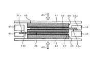
積層体40は、加熱加圧プレス成形機の加熱加圧プレス熱板41,42間に配置される。端子部31aは、図5に示すように、上金型43及び下金型44で挟持され、下金型44の段差部44aに端子部31aが着座される。また、端子部32aは、上金型45及び下金型46で挟持され、上金型45の段差部45aに端子部32aが着座される。プレス熱板41,42の少なくとも一方は、油圧ピストンのシリンダ(図示せず)などに接続されており、矢印A1,A2の方向、つまり積層体40の圧縮方向に移動自在である。
The laminate 40 is disposed between the heating and pressing press
次に、積層体40に、T2より高く、かつ、T1より低い温度で加熱加圧成形処理が施される。また、この加熱加圧成形処理時の圧力は、第2シート材21が溶融してなる溶融ポリマ63(後述)が流動する際に、十分に変形、流動できる程度の圧力であれば特に限定するものではない。
Next, the
この加熱加圧成形処理時、図6に示すように、スペーサポリマシート10の第1シート材11は溶融せず、形状が保持されることから、各金属プレート31,32の間に、ほぼ第1シート材11の厚さ分の間隔(隙間)が確保される。また、この隙間は、各金属プレート31,32の面方向にわたって均一となる。さらに、各モールドポリマシート20の第2シート材21は、加熱加圧成形処理によって溶融して溶融ポリマ63となり、この溶融ポリマ63が加熱加圧プレス熱板41,42、金型43,44、及び金型45,46で構成される空間61を埋めるように流動する。また、第1接着層12a,12b及び第2接着層22,22を構成する各接着剤は、融点T3がT2と同様に<T1の関係にあるため、加熱加圧成形処理によって一部が溶融し、溶融ポリマ63と共に流動する。T3は、T3≦T2、T3≧T2のいずれであってもよい。
As shown in FIG. 6, the
空間61内に行き渡った溶融ポリマ63が冷却、固化されることで、図7に示すように、各金属プレート31,32及び第1シート材11の周りがモールド部33で覆われたモールド成形体30が得られる。第1シート材11と各金属プレート31,32は、残存する第1接着層12a,12bを介して接着される。また、金属プレート31のモールド側面(図7中では下面)の大部分とモールド部33及び金属プレート32のモールド側面(図7中では上面)の大部分とモールド部33は、残存する第2接着層22,22を介して接着される。第1シート材11と残存する第1接着層12a,12bで、スペーサポリマ部34が構成される。尚、第1シート材11に第1接着層を設けていない場合、第1シート材11そのものがスペーサポリマ部34となる。
As the
ここで、第1接着層12a,12bを構成する融点がT1の絶縁性ポリマと、第2接着層22を構成する融点がT2の絶縁性ポリマの融点の差が大きいほど、モールド成形体30の製造が容易、かつ、安定となる。
Here, the larger the difference between the melting points of the insulating polymer having the melting point T1 constituting the first
融点がT1の絶縁性ポリマとしては、芳香族ポリマを主成分とするポリマ材が好適である。また、融点がT2の絶縁性ポリマとしては、ポリオレフィンを主成分とするポリマ材や、各種エラストマが好適である。つまり、融点がT1の絶縁性ポリマとしては、芳香族ポリマ材に対して強固な接着が得られる第1の接着機構を有する第1のポリマを用いることが好ましい。一方、融点がT2の絶縁性ポリマとしては、金属材に対して強固な接着が得られる第2の接着機構を有する第2のポリマを用いることが好ましい。各ポリマは、高い相溶性を有していることがより好ましい。これは、各金属プレート31,32のスペーサポリマシート10側に、第2接着層22を設けた場合、第1接着層12a,12bと第2接着層22,22が隣接することになる。この時、第1のポリマと第2のポリマが高い相溶性を有している場合、第1接着層12a,12bと第2接着層22,22が強固に接着され、延いては、各金属プレート31,32と第1シート材11をより強固に接着することができる。
As the insulating polymer having a melting point of T1, a polymer material mainly composed of an aromatic polymer is suitable. Further, as the insulating polymer having a melting point of T2, polymer materials mainly composed of polyolefin and various elastomers are suitable. That is, as the insulating polymer having a melting point T1, it is preferable to use a first polymer having a first adhesion mechanism that can provide strong adhesion to an aromatic polymer material. On the other hand, as the insulating polymer having a melting point of T2, it is preferable to use a second polymer having a second adhesion mechanism capable of obtaining strong adhesion to a metal material. It is more preferable that each polymer has high compatibility. In this case, when the second
第1の接着機構は、芳香族ポリマとの相溶性が高いスチレンブロックを有するスチレン系エラストマ(ポリマ)を接着剤として用いることで、接着剤と芳香族ポリマ材を加熱加圧すると、接着剤中のスチレンブロック部分と芳香族ポリマが相溶し、接着剤と芳香族ポリマ材が強固に接着される。ここで、芳香族ポリマとは、主鎖に芳香環を有するポリマを意味し、例えば、ポリフェニレンエーテル(PPE)、ポリエーテルイミド(PEI)、ポリカーボネート(PC)、ポリエーテルサルホン、ポリイミド、ポリフェニレンサルファイド、ポリサルホン、ポリエーテルエーテルケトン、などが代表的であるが、これらに限定するものではない。
一方、スチレンブロックを有するスチレン系エラストマとしては、例えば、スチレン−エチレンブチレン−スチレン共重合体(SEBS)、スチレン−エチレンプロピレン−スチレン共重合体(SEPS)、スチレン−ブチレン−スチレン共重合体(SBS)などのトリブロック共重合体、水添したスチレン−ブタジエンゴムなどのジブロック共重合体、などが挙げられる。
The first bonding mechanism uses a styrene-based elastomer (polymer) having a styrene block highly compatible with an aromatic polymer as an adhesive. When the adhesive and the aromatic polymer material are heated and pressurized, The styrene block portion and the aromatic polymer are compatible with each other, and the adhesive and the aromatic polymer material are firmly bonded. Here, the aromatic polymer means a polymer having an aromatic ring in the main chain, for example, polyphenylene ether (PPE), polyether imide (PEI), polycarbonate (PC), polyether sulfone, polyimide, polyphenylene sulfide. Typical examples include, but are not limited to, polysulfone, polyetheretherketone, and the like.
On the other hand, examples of the styrene elastomer having a styrene block include styrene-ethylenebutylene-styrene copolymer (SEBS), styrene-ethylenepropylene-styrene copolymer (SEPS), and styrene-butylene-styrene copolymer (SBS). And the like, and diblock copolymers such as hydrogenated styrene-butadiene rubber.
また、第2の接着機構は、酸変性又はエポキシ変性されたポリマを接着剤として用いることで、ポリマの酸基部位又はエポキシ基部位が金属表面の水分子や酸化物と水素結合し、接着剤と金属材が強固に接着される。ポリマの酸変性のなかで代表的なものとして、マレイン酸変性があり、その酸変性されて得られるポリマとしては、例えば、SBS、SEBS、ポリイソブチレン(PIB)などのエラストマ、ポリエチレン(PE)、ポリプロピレンなどのオレフィン系を始めとするポリマ、が挙げられる。一方、エポキシ基を有するポリマとしては、例えば、ポリエチレンとポリスチレンの共重合体をグリシジル化したもの、エチレン−グリシジルメタクリレート共重合体(EGMA)とポリスチレン(PS)との共重合体をグリシジル化したもの、などが挙げられる。 The second adhesive mechanism uses an acid-modified or epoxy-modified polymer as an adhesive, so that the acid group site or epoxy group site of the polymer is hydrogen-bonded to water molecules or oxides on the metal surface, and the adhesive And the metal material are firmly bonded. Typical examples of acid modification of polymers include maleic acid modification. Examples of polymers obtained by acid modification include elastomers such as SBS, SEBS, and polyisobutylene (PIB), polyethylene (PE), Polymers including olefins such as polypropylene are listed. On the other hand, examples of the polymer having an epoxy group include those obtained by glycidylating a copolymer of polyethylene and polystyrene, or glycidylating a copolymer of ethylene-glycidyl methacrylate copolymer (EGMA) and polystyrene (PS). , Etc.
本実施の形態に係るモールド成形体の製造方法によれば、金属プレート31,32の間にスペーサポリマシート10を配置した状態で、モールド部33のモールド被覆を行うことで、薄い絶縁層であるスペーサポリマ部34(図3(b)参照)を均一に形成することができる。つまり、金属プレート31,32をモールド部33でモールド被覆することができ、かつ、金属プレート31,32間を薄くて、厚さが均一な絶縁層を介して絶縁することができる。このスペーサポリマ部34の形成は、金属プレート31,32の面積の大きさ及び金属プレート31,32の離間距離の大きさに影響されることはない。また、スペーサポリマ部34の厚さ、すなわち金属プレート31,32間の隙間は金属プレート面方向にわたって均一である。
According to the method of manufacturing a molded body according to the present embodiment, a thin insulating layer is obtained by performing mold coating of the
また、本実施の形態に係るモールド成形体のモールド部33及びスペーサポリマ部34は、図11に示した従来のモールド成形体の製造方法のように射出成形で形成されるものではなく、加熱加圧成形により形成することができる。つまり、図6に示した加熱加圧プレス熱板41,42、金型43,44、及び金型45,46で構成される簡易な枠体を用い、モールド部33及びスペーサポリマ部34を製造することができ、射出成形用の高価な金型を用いる必要がない。よって、安価にモールド成形体30を製造することができる。
Further, the
また、本実施の形態に係るモールド成形体30の製造に用いる第2シート材21の形状、厚さは、最終的なモールド部33の体積を勘案し、最低限必要な体積量よりも10〜40%体積が多くなるように調整される。言い換えると、溶融ポリマ63のオーバーフロー量が、モールド部33の実際の体積量の10〜40%となるように、第2シート材21の形状、厚さが調整される。溶融ポリマ63のオーバーフロー量を十分にとることで、モールド部33の形状再現性が高くなる。
In addition, the shape and thickness of the second sheet material 21 used for manufacturing the molded
また、各金属プレート31,32をモールド部33でモールド被覆する際、各金属プレート31,32とモールド部33の間の密着強度、すなわち、各金属プレート31,32とモールド部33の剥離強度の大小が、モールド成形体30の絶縁性能を決定する主要因となる。よって、本実施の形態に係るモールド成形体30においては、各金属プレート31,32とモールド部33を接着剤を介して接着している。具体的には、第1シート材11及び第2シート材21の表面、各金属プレート31,32の表面、又は第1シート材11、第2シート材21、及び各金属プレート31,32の表面に、事前に接着層が形成される。その結果、各金属プレート31,32とモールド部33を均一に、かつ、強固に接着させることができ、延いてはモールド成形体30の絶縁性能を、長期にわたって良好に保持することができる。
Further, when the
また、融点がT2の絶縁性ポリマと各金属プレート31,32の接着強度は、酸変性(又はエポキシ変性)ポリマの酸変性(又はエポキシ変性)量を調整することで、自在に調整することができる。また、融点がT1の絶縁性ポリマと第1シート材11の接着強度は、スチレン系エラストマのスチレンブロック部分のスチレン量を調整することで、自在に調整することができる。
Further, the adhesive strength between the insulating polymer having a melting point of T2 and the
本実施の形態に係るモールド成形体30は、例えば、モールド型電源ブスプレートに好適である。
The molded
また、本実施の形態においては、図6に示したように、加熱加圧プレス熱板41,42、金型43,44、及び金型45,46で構成される枠体を用いてモールド部33を形成する場合について説明を行ったが、これに限定するものではない。例えば、枠体として、図8(a),図8(b)に示す下金枠81及び上金枠(図示せず)を用いてモールド部33を形成するようにしてもよい。下金枠81は、加熱加圧プレス熱板42及び下金型44,46を一体化したものに相当し、下金枠81内の空間部82に、モールドポリマシート20、金属プレート31、及びスペーサポリマシート10が収容される。一方、上金枠は、加熱加圧プレス熱板41及び上金型43,45を一体化したものに相当し、上金枠内の空間部に、金属プレート32及びモールドポリマシート20が収容される。
Further, in the present embodiment, as shown in FIG. 6, the mold part is formed by using a frame constituted by heating and pressing press
以上、本発明は、上述した実施の形態に限定されるものではなく、他にも種々のものが想定されることは言うまでもない。 As described above, the present invention is not limited to the above-described embodiment, and it goes without saying that various other things are assumed.
次に、本発明を実施例に基づいて説明するが、本発明はこの実施例に限定されるものではない。 Next, although this invention is demonstrated based on an Example, this invention is not limited to this Example.
板状金属体として2枚の銅板(200mm×280mm、厚さtが1mm)を準備し、図3(b)に示したようにラップ幅Lを210mm、銅板間の離間距離を0.4mmとして、ラップ領域を含むモールド領域(240mm×250mm)にモールド被覆を行った。 Prepare two copper plates (200mm x 280mm, thickness t is 1mm) as a plate-shaped metal body, and as shown in Fig. 3 (b), the lap width L is 210mm and the distance between the copper plates is 0.4mm. It was mold coating molding area (240 mm × 250 mm) containing wrap region.
(実施例1)
図1に示したように、両面に熱硬化型接着層を塗布形成したPPEシート(旭化成(株)製、ザイロン540Z、厚さtが0.4mm)を準備し、2枚の銅板のラップ領域より縦横が10mm大きいサイズ(220mm×230mm)に切断した。また、図2に示したように、片面にホットメルト接着剤層を塗布形成した難燃PE樹脂シート(宇部興産(株)製、Z555、厚さtが2.5m)を準備し、2枚の難燃PE樹脂シートの体積が、240mm×250mm×5mmのモールド成形体の体積から銅板及びPPEシートの体積を引いた値よりも大きくなるように、難燃PE樹脂シートを切断形成した(220mm×230mm×2.5mm)。さらに、図8に示した下金型81と、この下金枠81と一対の上金枠で構成される枠体を準備した。
Example 1
As shown in FIG. 1, a PPE sheet (manufactured by Asahi Kasei Co., Ltd., Zylon 540Z, thickness t is 0.4 mm) prepared by applying a thermosetting adhesive layer on both sides is prepared. It was cut into a size (220mm x 230mm) larger by 10mm in length and width. Also, as shown in FIG. 2, a flame-retardant PE resin sheet (manufactured by Ube Industries, Z555, thickness t is 2.5 m) having a hot-melt adhesive layer formed on one side is prepared. The flame retardant PE resin sheet was cut and formed so that the volume of the flame retardant PE resin sheet was larger than the value obtained by subtracting the volume of the copper plate and the PPE sheet from the volume of the molded body of 240 mm × 250 mm × 5 mm (220 mm × 230mm x 2.5mm). Further, a
この枠体内に、難燃PE樹脂シート、銅板、PPEシート、銅板、難燃PE樹脂シートの順に重ねた積層体を配置した。この積層体を、枠体ごと加熱加圧プレス熱板間に挟み、130℃に加熱した加熱加圧プレス成形機にセットした。十分な予熱を行った後、0.5MPaの圧力を加えて加熱加圧成形処理を施し、図7に示した構造のモールド成形体(試料1)を作製した。 In this frame, a laminated body in which a flame retardant PE resin sheet, a copper plate, a PPE sheet, a copper plate, and a flame retardant PE resin sheet were stacked in this order was disposed. The laminate was sandwiched between the heating and pressing press hot plates together with the frame and set in a heating and pressing press molding machine heated to 130 ° C. After sufficient preheating, a pressure of 0.5 MPa was applied to perform heat and pressure molding treatment to produce a molded body (sample 1) having the structure shown in FIG.
その結果、試料1においては、1辺が200mm程度、離間距離が0.4mmの銅板間に、非常に薄い均一な絶縁層(スペーサポリマ部)を形成することができた。この試料1の、部分放電発生消滅(10pC)電圧を計測した結果、8kV以上の値が得られ、このモールド成形体の銅板間及び銅板周囲において、電気的絶縁に悪影響を与える大きさのボイドの発生は無かった。
As a result, in
また、この試料1に対し、−25℃〜105℃のヒートサイクルを100回繰り返した後、再度、部分放電開始消滅電圧を測定した結果、ヒートサイクルを加える以前と同じ8kV以上の値が得られた。つまり、ヒートサイクルを加えても、銅板とPPEシートの界面に剥離やボイドは発生しておらず、銅板とPPEシートが強固に接着されていることが確認できた。
In addition, after repeating the heat cycle of −25 ° C. to 105 ° C. 100 times for this
(比較例1)
枠体として図10に示した射出成形金型110を準備した。
(Comparative Example 1)
The
銅板を射出成形金型110のキャビティ113内に配置した後、溶融したポリフェニルエーテル(PPE、旭化成(株)製、ザイロン540Z)をキャビティ113内に射出して射出成型を行い、モールド成形体(試料3)を作製した。
After placing the copper plate in the
この試料3の、部分放電発生消滅(10pC)電圧を計測した結果、1kV以下と非常に低い値となった。このモールド成形体を切断し、断面を観察した結果、銅板間に電気的絶縁に悪影響を与える大きなボイドの発生が確認された。 As a result of measuring the partial discharge occurrence extinction (10 pC) voltage of Sample 3, it was a very low value of 1 kV or less. As a result of cutting this molded body and observing the cross section, generation of large voids that adversely affect the electrical insulation between the copper plates was confirmed.
30 モールド成形体
31,32 金属プレート(板状金属体)
33 モールド部
34 スペーサポリマ部
30 Molded
33
Claims (5)
Priority Applications (4)
| Application Number | Priority Date | Filing Date | Title |
|---|---|---|---|
| JP2005224244A JP4815935B2 (en) | 2005-08-02 | 2005-08-02 | Method for producing molded body |
| US11/497,338 US20070031646A1 (en) | 2005-08-02 | 2006-08-02 | Molded product and manufacturing method thereof |
| CN200610108360A CN100581795C (en) | 2005-08-02 | 2006-08-02 | Molded product and manufacturing method thereof |
| US12/768,794 US8568547B2 (en) | 2005-08-02 | 2010-04-28 | Molded product and manufacturing method thereof |
Applications Claiming Priority (1)
| Application Number | Priority Date | Filing Date | Title |
|---|---|---|---|
| JP2005224244A JP4815935B2 (en) | 2005-08-02 | 2005-08-02 | Method for producing molded body |
Publications (2)
| Publication Number | Publication Date |
|---|---|
| JP2007038490A JP2007038490A (en) | 2007-02-15 |
| JP4815935B2 true JP4815935B2 (en) | 2011-11-16 |
Family
ID=37698997
Family Applications (1)
| Application Number | Title | Priority Date | Filing Date |
|---|---|---|---|
| JP2005224244A Expired - Fee Related JP4815935B2 (en) | 2005-08-02 | 2005-08-02 | Method for producing molded body |
Country Status (3)
| Country | Link |
|---|---|
| US (2) | US20070031646A1 (en) |
| JP (1) | JP4815935B2 (en) |
| CN (1) | CN100581795C (en) |
Families Citing this family (27)
| Publication number | Priority date | Publication date | Assignee | Title |
|---|---|---|---|---|
| JP5446722B2 (en) * | 2009-10-26 | 2014-03-19 | 日立金属株式会社 | Busbar module manufacturing method and busbar module |
| JP2011143711A (en) | 2009-12-16 | 2011-07-28 | Hitachi Cable Ltd | Insert molding method and insert molded product |
| JP5549491B2 (en) * | 2010-09-06 | 2014-07-16 | 日立金属株式会社 | Busbar module manufacturing method and busbar module |
| KR101282627B1 (en) * | 2011-09-07 | 2013-07-12 | 현대자동차주식회사 | End plate for fuel cell having warpage preventing plate |
| JP6082547B2 (en) | 2012-09-04 | 2017-02-15 | 株式会社アテックス | Busbar insert resin molded product manufacturing method |
| JP6183288B2 (en) | 2014-05-07 | 2017-08-23 | 株式会社豊田自動織機 | Electric compressor |
| JP6490465B2 (en) * | 2015-03-23 | 2019-03-27 | 古河電気工業株式会社 | Cable connection structure and manufacturing method thereof |
| JP6487769B2 (en) | 2015-05-18 | 2019-03-20 | サンコール株式会社 | Manufacturing method of laminated busbar unit |
| JP2019084740A (en) * | 2017-11-06 | 2019-06-06 | 株式会社デンソー | Energizing member module and method for manufacturing the same |
| US12062700B2 (en) | 2018-04-04 | 2024-08-13 | Qorvo Us, Inc. | Gallium-nitride-based module with enhanced electrical performance and process for making the same |
| US12046505B2 (en) | 2018-04-20 | 2024-07-23 | Qorvo Us, Inc. | RF devices with enhanced performance and methods of forming the same utilizing localized SOI formation |
| JP6973271B2 (en) * | 2018-04-26 | 2021-11-24 | トヨタ自動車株式会社 | Protector and protector manufacturing method |
| EP3818558A1 (en) | 2018-07-02 | 2021-05-12 | Qorvo US, Inc. | Rf semiconductor device and manufacturing method thereof |
| US11646242B2 (en) | 2018-11-29 | 2023-05-09 | Qorvo Us, Inc. | Thermally enhanced semiconductor package with at least one heat extractor and process for making the same |
| US12057374B2 (en) | 2019-01-23 | 2024-08-06 | Qorvo Us, Inc. | RF devices with enhanced performance and methods of forming the same |
| US12046570B2 (en) | 2019-01-23 | 2024-07-23 | Qorvo Us, Inc. | RF devices with enhanced performance and methods of forming the same |
| US12046483B2 (en) | 2019-01-23 | 2024-07-23 | Qorvo Us, Inc. | RF devices with enhanced performance and methods of forming the same |
| EP3915134A1 (en) | 2019-01-23 | 2021-12-01 | Qorvo US, Inc. | Rf semiconductor device and manufacturing method thereof |
| US12125825B2 (en) | 2019-01-23 | 2024-10-22 | Qorvo Us, Inc. | RF devices with enhanced performance and methods of forming the same |
| US12074086B2 (en) | 2019-11-01 | 2024-08-27 | Qorvo Us, Inc. | RF devices with nanotube particles for enhanced performance and methods of forming the same |
| US11923238B2 (en) * | 2019-12-12 | 2024-03-05 | Qorvo Us, Inc. | Method of forming RF devices with enhanced performance including attaching a wafer to a support carrier by a bonding technique without any polymer adhesive |
| US12129168B2 (en) | 2019-12-23 | 2024-10-29 | Qorvo Us, Inc. | Microelectronics package with vertically stacked MEMS device and controller device |
| EP4260369A2 (en) | 2020-12-11 | 2023-10-18 | Qorvo US, Inc. | Multi-level 3d stacked package and methods of forming the same |
| US12062571B2 (en) | 2021-03-05 | 2024-08-13 | Qorvo Us, Inc. | Selective etching process for SiGe and doped epitaxial silicon |
| JP7007512B1 (en) | 2021-05-31 | 2022-02-10 | 株式会社アテックス | Conductive member and its manufacturing method |
| CN115195158B (en) * | 2022-06-22 | 2024-04-12 | 北京玻钢院复合材料有限公司 | Die and method for preparing composite material and structural member interface compression shear strength test sample |
| TWI846558B (en) * | 2023-08-07 | 2024-06-21 | 薩摩亞商大煜國際有限公司 | Methods of bonding dissimilar metals |
Family Cites Families (14)
| Publication number | Priority date | Publication date | Assignee | Title |
|---|---|---|---|---|
| US3346789A (en) * | 1965-10-22 | 1967-10-10 | Sprague Electric Co | Electrical capacitor with impregnated metallized electrode |
| US3550269A (en) * | 1966-03-26 | 1970-12-29 | Furukawa Electric Co Ltd | Method of manufacturing insulated bus bar |
| US4133101A (en) * | 1972-09-18 | 1979-01-09 | Amp Incorporated | Method of fabricating a laminated bus bar |
| JPH10214521A (en) * | 1997-01-31 | 1998-08-11 | Tokai Kogyo Kk | Multilayer conductive material arrangement structure, multilayer conductive material device and method of manufacturing the same |
| US6059983A (en) * | 1997-09-23 | 2000-05-09 | Hewlett-Packard Company | Method for fabricating an overcoated printed circuit board with contaminant-free areas |
| JP3455116B2 (en) * | 1998-09-30 | 2003-10-14 | 株式会社三井ハイテック | Method for manufacturing semiconductor device |
| JP2000149667A (en) | 1998-11-13 | 2000-05-30 | Furukawa Electric Co Ltd:The | Laminated busbar |
| JP4043640B2 (en) | 1999-04-09 | 2008-02-06 | 古河電気工業株式会社 | Laminated bus bar and manufacturing method thereof |
| US6572723B1 (en) * | 2000-06-30 | 2003-06-03 | Owens Corning Fiberglas Technology, Inc. | Process for forming a multilayer, multidensity composite insulator |
| JP2002288613A (en) * | 2001-03-27 | 2002-10-04 | Osaka Gas Co Ltd | Resonance tag and manufacturing method therefor |
| JP4771348B2 (en) * | 2001-05-14 | 2011-09-14 | 日東電工株式会社 | Manufacturing method of optical path conversion film and liquid crystal display device |
| US20040185237A1 (en) * | 2001-08-07 | 2004-09-23 | Kohichiro Kawate | Sheet for sealing electrical wiring |
| JP3684441B2 (en) * | 2001-10-30 | 2005-08-17 | 株式会社日立製作所 | Inverter device |
| JP2004295163A (en) * | 2003-03-25 | 2004-10-21 | Osaka Gas Co Ltd | Resonance tag and its manufacturing method |
-
2005
- 2005-08-02 JP JP2005224244A patent/JP4815935B2/en not_active Expired - Fee Related
-
2006
- 2006-08-02 CN CN200610108360A patent/CN100581795C/en not_active Expired - Fee Related
- 2006-08-02 US US11/497,338 patent/US20070031646A1/en not_active Abandoned
-
2010
- 2010-04-28 US US12/768,794 patent/US8568547B2/en not_active Expired - Fee Related
Also Published As
| Publication number | Publication date |
|---|---|
| CN100581795C (en) | 2010-01-20 |
| CN1907692A (en) | 2007-02-07 |
| US8568547B2 (en) | 2013-10-29 |
| US20070031646A1 (en) | 2007-02-08 |
| US20100206468A1 (en) | 2010-08-19 |
| JP2007038490A (en) | 2007-02-15 |
Similar Documents
| Publication | Publication Date | Title |
|---|---|---|
| JP4815935B2 (en) | Method for producing molded body | |
| US10907268B2 (en) | Method for producing multi-layer bus bar unit | |
| JP3809491B2 (en) | Fuel cell separator | |
| CN105938910B (en) | Fuel cell single cell and method for manufacturing fuel cell single cell | |
| KR102738454B1 (en) | Packaging material for battery | |
| CN113410552B (en) | Battery packaging material and battery | |
| CN106558658B (en) | Sealant film for exterior member of power storage device, exterior member for power storage device, and power storage device | |
| JP2004055350A (en) | Fuel cell seal structure and method of manufacturing the same | |
| CN112913070A (en) | Exterior material for storage device, method for producing the same, and storage device | |
| CN106558657A (en) | The exterior component encapsulant film of electrical storage device, electrical storage device exterior component and electrical storage device | |
| KR20200010110A (en) | Method for manufacturing fuel cell and fuel cell | |
| CN113646158B (en) | Bonding method and high-frequency dielectric heating adhesive sheet | |
| WO2012132956A1 (en) | Method of manufacturing cladding for laminated battery | |
| JP4618211B2 (en) | Method for producing molded body | |
| KR20230011575A (en) | Film for lead tab of secondary battery | |
| JP2018147700A (en) | Method of manufacturing fuel battery cell | |
| JP2000156215A (en) | Silicone resin-coated metal composite and method for producing the same | |
| JP2011046196A (en) | Mold | |
| US20090280374A2 (en) | Process for sealing plates in a fuel cell | |
| JP2016170961A (en) | Method of manufacturing fuel battery single cell | |
| JP2010274603A (en) | Molded resin molding | |
| EP2686902B1 (en) | Fuel cell plate bonding method and arrangement | |
| JP2010274602A (en) | Molded resin molding | |
| JP2023510422A (en) | Box-in-box structure with thermal clay, its use and method of manufacture | |
| JP7698517B2 (en) | Adhesion method |
Legal Events
| Date | Code | Title | Description |
|---|---|---|---|
| A621 | Written request for application examination |
Free format text: JAPANESE INTERMEDIATE CODE: A621 Effective date: 20070914 |
|
| A977 | Report on retrieval |
Free format text: JAPANESE INTERMEDIATE CODE: A971007 Effective date: 20100309 |
|
| A131 | Notification of reasons for refusal |
Free format text: JAPANESE INTERMEDIATE CODE: A131 Effective date: 20100413 |
|
| A521 | Request for written amendment filed |
Free format text: JAPANESE INTERMEDIATE CODE: A523 Effective date: 20100611 |
|
| A131 | Notification of reasons for refusal |
Free format text: JAPANESE INTERMEDIATE CODE: A131 Effective date: 20110517 |
|
| A521 | Request for written amendment filed |
Free format text: JAPANESE INTERMEDIATE CODE: A523 Effective date: 20110708 |
|
| TRDD | Decision of grant or rejection written | ||
| A01 | Written decision to grant a patent or to grant a registration (utility model) |
Free format text: JAPANESE INTERMEDIATE CODE: A01 Effective date: 20110802 |
|
| A01 | Written decision to grant a patent or to grant a registration (utility model) |
Free format text: JAPANESE INTERMEDIATE CODE: A01 |
|
| A61 | First payment of annual fees (during grant procedure) |
Free format text: JAPANESE INTERMEDIATE CODE: A61 Effective date: 20110815 |
|
| FPAY | Renewal fee payment (event date is renewal date of database) |
Free format text: PAYMENT UNTIL: 20140909 Year of fee payment: 3 |
|
| R150 | Certificate of patent or registration of utility model |
Free format text: JAPANESE INTERMEDIATE CODE: R150 |
|
| S111 | Request for change of ownership or part of ownership |
Free format text: JAPANESE INTERMEDIATE CODE: R313111 |
|
| R350 | Written notification of registration of transfer |
Free format text: JAPANESE INTERMEDIATE CODE: R350 |
|
| LAPS | Cancellation because of no payment of annual fees |