JP4786532B2 - Elevator with cable-driven cage - Google Patents
Elevator with cable-driven cage Download PDFInfo
- Publication number
- JP4786532B2 JP4786532B2 JP2006515668A JP2006515668A JP4786532B2 JP 4786532 B2 JP4786532 B2 JP 4786532B2 JP 2006515668 A JP2006515668 A JP 2006515668A JP 2006515668 A JP2006515668 A JP 2006515668A JP 4786532 B2 JP4786532 B2 JP 4786532B2
- Authority
- JP
- Japan
- Prior art keywords
- cage
- elevator
- cable
- vertical beam
- case
- Prior art date
- Legal status (The legal status is an assumption and is not a legal conclusion. Google has not performed a legal analysis and makes no representation as to the accuracy of the status listed.)
- Expired - Fee Related
Links
- 230000001681 protective effect Effects 0.000 claims description 20
- 230000005540 biological transmission Effects 0.000 claims description 8
- 238000001816 cooling Methods 0.000 claims description 2
- 238000010438 heat treatment Methods 0.000 claims description 2
- 238000007596 consolidation process Methods 0.000 claims 1
- 239000000463 material Substances 0.000 description 7
- 210000000078 claw Anatomy 0.000 description 4
- 238000005452 bending Methods 0.000 description 2
- 238000009434 installation Methods 0.000 description 2
- 238000007789 sealing Methods 0.000 description 2
- XLYOFNOQVPJJNP-UHFFFAOYSA-N water Substances O XLYOFNOQVPJJNP-UHFFFAOYSA-N 0.000 description 2
- 230000002411 adverse Effects 0.000 description 1
- 239000004567 concrete Substances 0.000 description 1
- 230000000694 effects Effects 0.000 description 1
- 238000005516 engineering process Methods 0.000 description 1
- 239000011521 glass Substances 0.000 description 1
- 238000012423 maintenance Methods 0.000 description 1
- 239000002184 metal Substances 0.000 description 1
- 238000000034 method Methods 0.000 description 1
- 230000003068 static effect Effects 0.000 description 1
Images


Classifications
-
- B—PERFORMING OPERATIONS; TRANSPORTING
- B66—HOISTING; LIFTING; HAULING
- B66B—ELEVATORS; ESCALATORS OR MOVING WALKWAYS
- B66B11/00—Main component parts of lifts in, or associated with, buildings or other structures
- B66B11/0035—Arrangement of driving gear, e.g. location or support
- B66B11/004—Arrangement of driving gear, e.g. location or support in the machine room
-
- B—PERFORMING OPERATIONS; TRANSPORTING
- B66—HOISTING; LIFTING; HAULING
- B66B—ELEVATORS; ESCALATORS OR MOVING WALKWAYS
- B66B11/00—Main component parts of lifts in, or associated with, buildings or other structures
- B66B11/0065—Roping
- B66B11/008—Roping with hoisting rope or cable operated by frictional engagement with a winding drum or sheave
-
- B—PERFORMING OPERATIONS; TRANSPORTING
- B66—HOISTING; LIFTING; HAULING
- B66B—ELEVATORS; ESCALATORS OR MOVING WALKWAYS
- B66B7/00—Other common features of elevators
- B66B7/02—Guideways; Guides
- B66B7/021—Guideways; Guides with a particular position in the shaft
-
- B—PERFORMING OPERATIONS; TRANSPORTING
- B66—HOISTING; LIFTING; HAULING
- B66B—ELEVATORS; ESCALATORS OR MOVING WALKWAYS
- B66B7/00—Other common features of elevators
- B66B7/06—Arrangements of ropes or cables
Landscapes
- Engineering & Computer Science (AREA)
- Civil Engineering (AREA)
- Mechanical Engineering (AREA)
- Structural Engineering (AREA)
- Lift-Guide Devices, And Elevator Ropes And Cables (AREA)
- Types And Forms Of Lifts (AREA)
- Forklifts And Lifting Vehicles (AREA)
Abstract
Description
本発明はケーブル駆動のケージを有する、垂直なガイドレールを備えたエレベータに関する。 The present invention relates to an elevator with a vertical guide rail having a cable-driven cage.
通常、エレベータは垂直なシャフト内に設置され、そのシャフトは建築構造の一部であるか又は建築構造に強固に連結しているので、エレベータは建築構造を有するユニットを形成している。シャフトはコンクリート、金属、ガラス又はこれらの材料を組み合わせて製造されており、重厚且つ高価な構造体である。しかし、湿気はケーブルとそれに配置した駆動輪の間の摩擦に悪影響を及ぼすので、ケージに連結したケーブルを風雨、特に湿気の影響から保護するために、シャフトは絶対に必要である。拘束を受けないエレベータにおいてシャフトのコスト高を避けるため、エレベータのケージをピストンで直接に駆動するか又はケーブルと関連付けて2:1の比率で伝道装置を垂直方向に駆動することが実用的に知られている。しかし、このようなエレベータでは揚高はきわめて限定され、速度は1m/秒以上にはできない。 Usually, the elevator is installed in a vertical shaft, which is part of the building structure or is firmly connected to the building structure, so that the elevator forms a unit having the building structure. The shaft is made of concrete, metal, glass or a combination of these materials, and is a heavy and expensive structure. However, since moisture adversely affects the friction between the cable and the drive wheels disposed on it, a shaft is absolutely necessary to protect the cable connected to the cage from the effects of wind and rain, especially moisture. In order to avoid high shaft costs in unrestrained elevators, it is practically known to drive the elevator car directly with a piston or in conjunction with a cable to drive the transmission device in a 2: 1 ratio. It has been. However, in such an elevator, the lifting height is extremely limited, and the speed cannot be higher than 1 m / sec.
本発明の課題は、簡単な構造で、より安全に上述のように拘束を受けずに運転できるエレベータを供給することにある。 An object of the present invention is to provide an elevator that can be operated safely and without being restricted as described above, with a simple structure.
本発明によれば、ケーブルをケージの両側のそれぞれのケースに配置し、共通の駆動輪により駆動させることにより課題が解決できる。 According to the present invention, the problem can be solved by arranging the cables in the respective cases on both sides of the cage and driving them with a common drive wheel.
この処置により、拘束を受けないエレベータを運転する際、ケーブルを風雨、特に湿気から保護するためのシャフトを設置する必要がなくなる。ケーブルをケース内に収納することにより、エレベータの確実な運転が保証される。 This measure eliminates the need to install a shaft to protect the cable from wind and rain, especially moisture, when operating an unconstrained elevator. By storing the cable in the case, reliable operation of the elevator is guaranteed.
目的に適うように、ケージの両側のそれぞれのケーブルは、一端がケージに他端がカウンタウェイトに連結されている。これにより、相互に作用する力が相殺されるので、ケーブルへ均等な負荷が掛かり且つ駆動輪の推進出力を減らすことができる。小型の構造を達成するため、垂直梁のケージ及びガイドレールに面した側とは逆の側にカウンタウェイトを備えている。ケージの両側に配置した垂直梁のみがエレベータを静的に保つ構成要素である。垂直梁は、例えば扉を備えたケージの前面域に配置し且つ建物に連結してもよい。更に、垂直梁を、例えば伸長ケーブルにより保持して、エレベータを自立させることも可能である。このような垂直梁、従ってエレバータの設置方法は、例えば、テント構造、展示用スタンド又は類似の比較的不安定な構築物において使用することもできる。 To suit the purpose, each cable on both sides of the cage is connected at one end to the cage and at the other end to a counterweight. As a result, the forces acting on each other are canceled out, so that an even load is applied to the cable and the propulsion output of the drive wheels can be reduced. In order to achieve a compact structure, a counterweight is provided on the opposite side of the vertical beam facing the cage and guide rail. Only the vertical beams placed on both sides of the cage are the components that keep the elevator static. The vertical beam may for example be arranged in the front area of a cage with a door and connected to the building. Furthermore, it is possible to hold the vertical beam, for example, by an extension cable, so that the elevator is self-supporting. Such vertical beam, and thus ereverta installation methods, can also be used, for example, in tent structures, exhibition stands or similar relatively unstable structures.
垂直梁を曲げ並びに折れに強く且つ圧力に安定であるために、各垂直梁を断面がH字形梁として形成し、ケース内に配置することが好ましい。エレベータ全体を開放された状態、従って追加の支えを必要としないように、垂直梁を例えば少なくとも1つの基礎に固定してもよい。 In order for the vertical beams to be resistant to bending and bending and to be stable in pressure, it is preferable to form each vertical beam as an H- shaped cross section and arrange it in the case. The vertical beam may be fixed to at least one foundation, for example, so that the entire elevator is open, and thus no additional support is required.
空間を節約するようにケーブルを通すため、垂直梁はその上端にケーブル用の駆動輪並びに複数の方向転換輪を設置する水平梁を備え、その水平梁は、架橋するように2つの垂直梁の間を延びている。方向転換輪は、ケーブルが方向転換輪を技術的規制に対応する角度で包むように、駆動輪を配置する。目的に適うように、伝道装置の切換機構の下で駆動輪を駆動するモータを水平梁上に固定する。適切にモータを設計すれば、伝動装置を備える必要はなく、従って駆動装置はギアレスで操作できる。更に、水平梁は電子制御装置を備えている。電子制御装置、モータ及び伝動装置をケージの下に配置して、ケーブルを対応する方向変換輪を介してケージへと通すこともできる。 In order to pass the cable in order to save space, the vertical beam is equipped with a horizontal beam with a driving wheel for the cable and a plurality of turning wheels at its upper end, and the horizontal beam is bridged between the two vertical beams so as to bridge. It extends between. The direction change wheel arranges the drive wheel so that the cable wraps the direction change wheel at an angle corresponding to the technical regulations. To meet the purpose, a motor for driving the driving wheel is fixed on the horizontal beam under the switching mechanism of the transmission device. If the motor is designed properly, it is not necessary to have a transmission, so the drive can be operated without gears. Furthermore, the horizontal beam is equipped with an electronic control unit. It is also possible to place the electronic control device, the motor and the transmission device under the cage and pass the cable through the corresponding turning wheel into the cage.
特に、水平梁とは反対側の垂直梁の端部をシャフトピット中に固定する。例えば、コンクリートで固めたシャフトピットは垂直梁を確実に固定し、ケージの下端の下に開放空間を生成する。垂直梁を更に補強するため、複数の互いに離れたクロスバーを用いて垂直梁を互いに連結する。 In particular, the end of the vertical beam opposite to the horizontal beam is fixed in the shaft pit. For example, a concrete-hardened shaft pit securely fixes a vertical beam and creates an open space under the lower end of the cage. To further reinforce the vertical beams, the vertical beams are connected to each other using a plurality of spaced crossbars.
垂直梁の各々のブリッジはケージと平行に整列し、ケージに向いた側にガイドレールを配置することが好ましい。これにより、ガイドレールは、フランジ及び垂直梁のブリッジにより形成されるU字状の空間内部に配置される。本発明では、制御できないカウンタウェイトの揺動を防ぐため、垂直梁のガイドレールと反対側のフランジに案内手段を備え、カウンタウェイトが垂直梁のU字状の凹所に在るようにしている。垂直梁のブリッジに対して互いにカウンタウェイト及びガイドレールの配置することにより、垂直梁は圧縮荷重を受けることになる。 Each bridge of the vertical beam is preferably aligned parallel to the cage and guide rails are arranged on the side facing the cage. As a result, the guide rail is arranged inside a U-shaped space formed by the bridge of the flange and the vertical beam. In the present invention, in order to prevent the swing of the counterweight that cannot be controlled, the flange on the opposite side to the guide rail of the vertical beam is provided with guide means so that the counterweight is located in the U-shaped recess of the vertical beam. . By arranging the counterweight and the guide rail with respect to the bridge of the vertical beam, the vertical beam receives a compressive load.
カウンタウェイトが余り磨耗しないように、案内手段はフランジと向かい合って固定したアングル材として形成することが好ましく、カウンタウェイトに固定した案内ローラは案内手段に支持されている。この際、例えばアングル材の角はカウンタウェイトの方向を示し、案内ローラをその駆動面がアングル材の脚部上を完全に回転するように配置する。 The guide means is preferably formed as an angle member fixed so as to face the flange so that the counterweight is not worn too much, and the guide roller fixed to the counterweight is supported by the guide means. At this time, for example, the angle of the angle member indicates the direction of the counterweight, and the guide roller is arranged so that the driving surface thereof completely rotates on the leg portion of the angle member.
断面がT字状のガイドレールの脚部が垂直梁のブリッジに平行になり、ケージ側のローラに案内されるブリッジがケージを向くように配置されるように、ガイドレールは保持形材を介して垂直梁のブリッジに固定することが好ましい。ガイドレール及びローラはケージの両側に配置しているので、ケージは安定に支持され、ケージの上下方向のみが可能となっている。 The guide rail is placed through the holding profile so that the legs of the T-shaped guide rail are parallel to the bridge of the vertical beam and the bridge guided by the roller on the cage side faces the cage. And is preferably fixed to a bridge of vertical beams. Since the guide rail and the roller are arranged on both sides of the cage, the cage is stably supported, and only the vertical direction of the cage is possible.
比較的に遅延無くガイドレールを支持するため、例えばガイドレールを保持形材に締付爪により固定して、一方で保持形材を垂直梁に溶接してもよい。更に、本発明によれば、アングル材を介してローラをケージの枠に結合しているU字状形材により保持してもよい。アングル材の代わりに、例えばU字状又は平面状形材の梁も使用でき、例えばU字状形材をアングル材に置き換えてもよい。 In order to support the guide rail with relatively little delay, for example, the guide rail may be fixed to the holding profile with clamping claws while the holding profile is welded to the vertical beam. Furthermore, according to the present invention, the roller may be held by a U-shaped member that is coupled to the cage frame via an angle member. Instead of the angle member, for example, a U-shaped or planar shaped beam can be used. For example, the U-shaped member may be replaced with an angle member.
枠を断面U字状形材から組み立てることが好ましく、各々に対応する垂直梁に向かって配列した脚を有する形材はケージの全高に渉って延びており、形材の一方の脚はアングル材の脚と連結し、他方の脚はU字状形材を保持している。このような比較的堅牢な構造のため、ローラはガイドレールに絶えず接することが確実となる。 It is preferable to assemble the frame from a U-shaped cross section, with the profiles having legs arranged toward the corresponding vertical beams extending along the entire height of the cage, with one leg of the profile being an angle It connects with the leg of the material, and the other leg holds the U-shaped profile. Such a relatively robust structure ensures that the roller is in constant contact with the guide rail.
ケージと垂直梁又はそれに連結したガイドレールの連結領域を風雨の影響から保護するため、ケージ両側に全高に渉って保護ケースを配置することが好ましい。該保護ケースは枠の形材を覆い且つアングル材の脚に配置した形材用の開口部を備え、アングル材は垂直梁を保持しているケースの空隙を貫通している。このため、湿気が入り込む保護ケースの開口部及びケースの空隙を比較的小さくでき、ケージを垂直梁の間に確実に保持できる。開口部をケースの空隙を貫通している保護ケースの2つの突出部の間に形成することが好ましい。このため、ケースと保護ケースが開口領域で重なり合い水の浸入を防いでいる。保護ケースの突出部に接している互いにV字を形成するようにシール片をケースの両側に備えることが好ましい。これにより、保護ケース又はケースに降り注ぐ雨又は雪がケース内部に入り、ケーブル又はガイドへと達するのを防ぐ。 In order to protect the connection area between the cage and the vertical beam or the guide rail connected thereto from the influence of wind and rain, it is preferable to arrange protective cases on both sides of the cage over the entire height. The protective case covers the frame shape and has an opening for the shape arranged on the leg of the angle material, and the angle material penetrates the gap of the case holding the vertical beam. For this reason, the opening of the protective case where moisture enters and the gap of the case can be made relatively small, and the cage can be reliably held between the vertical beams. The opening is preferably formed between the two protrusions of the protective case that penetrates the gap of the case. For this reason, the case and the protective case overlap each other in the opening region to prevent water from entering. It is preferable that seal pieces are provided on both sides of the case so as to form a V shape that is in contact with the protruding portion of the protective case. This prevents rain or snow falling on the protective case or case from entering the case and reaching the cable or guide.
電気ケーブルはガイドレールのケース内部に、安全装置の作動機構は別のガイドレールのケース内部に配置することが好ましい。電気ケーブルはケースの空隙及び保護ケースの開口部を通ってケージの内部へ突出していることが好ましい。これにより、電気ケーブルはケージ内で使用電力並びにエレベータ及びケース内に収納して風雨から保護された2つのガイドレールに作用する最新技術に基づいた安全装置の作動機構を制御する電源を供給することができる。 It is preferable that the electric cable is disposed inside the case of the guide rail and the operating mechanism of the safety device is disposed inside the case of another guide rail. The electrical cable preferably protrudes into the cage through the gap in the case and the opening in the protective case. Thereby, the electric cable supplies the power used to control the working mechanism of the safety device based on the latest technology that acts on the two guide rails housed in the elevator and case and protected from the wind and rain in the cage. Can do.
駆動輪及び方向転換輪をカバーで覆うことが好ましい。当然のことであるが、このカバーの下には、モータ、伝道装置並びに制御装置も配置され、風雨から保護されているので、エレベータを開放空間に設置するのに適している。カバーは保守作業を考慮して旋回可能に取り付けるか、フラップ又は扉を備えてもよい。 It is preferable to cover the driving wheel and the direction changing wheel with a cover. As a matter of course, a motor, a transmission device, and a control device are also arranged under the cover, and are protected from wind and rain, so that the elevator is suitable for installation in an open space. The cover may be pivotably mounted in consideration of maintenance work, or may be provided with a flap or a door.
更に、本発明の好適な構成によれば、一方は対応するカウンタウェイトに他方をケージに固定した複数のワイヤケーブルをケージの両側に備え、ワイヤケーブルは対応する垂直梁の下を巡り伸長錘を有する方向転換輪を保持している。制動装置ではない安全装置を作動させるため、巻上げ機をワイヤケーブルに固定して制動機が作動するとカウンタウェイトがケージを上方又は下方に引っ張ることになる。上昇並びに下降行程においてケージを制動することができる場合には、安全装置が各々の行程で作動することが必要である。下降行程において緊急に制動した後には、ケージは上方へ動かす必要がある。このため、カウンタウェイトに配置したワイヤケーブルの部分に巻上げ機の一端を固定し、他端は伸長錘を有する方向変換輪を備えたシャフト孔の遥か下に固定されている。巻上げ機が伸張されるように負荷を掛けると、カウンタウェイトは下方へ、その結果ケージは上方へ移動し、安全装置が外れる。上方行程中に緊急の制動を掛けた後には、ケージを下方に移動させる必要があり、更に巻上げ機の一端をワイヤケーブルのカウンタウェイトに配置した部分に固定し、他端を遥か上方に固定する。伸長錘は、例えば方向転換輪を固定することにより固定される。結果として、エレベータの駆動制動を解除すると、安全装置が開放されるように、ケージは下方に移動する。 Further, according to a preferred configuration of the present invention, a plurality of wire cables, one of which is fixed to the corresponding counterweight and the other of which is fixed to the cage, are provided on both sides of the cage. Holding the turning wheel. In order to operate a safety device that is not a braking device, the counterweight pulls the cage upward or downward when the hoisting device is fixed to the wire cable and the braking device is operated. If the cage can be braked on the up and down strokes, it is necessary for the safety device to operate on each stroke. After emergency braking on the down stroke, the cage needs to be moved upward. For this reason, one end of the hoisting machine is fixed to the portion of the wire cable arranged on the counterweight, and the other end is fixed far below the shaft hole provided with the direction change wheel having the extension weight. When a load is applied so that the winder is extended, the counterweight moves downward, so that the cage moves upward and the safety device is released. After emergency braking is applied during the upward stroke, the cage needs to be moved downward, and one end of the hoisting machine is fixed to the part of the wire cable counterweight and the other end is fixed far upward. . The extension weight is fixed, for example, by fixing a direction changing wheel. As a result, when the drive braking of the elevator is released, the cage moves downward so that the safety device is released.
エレベータの使用者又はその駆動部材は寒さ及び/又は暑さから保護するように、ケージ及び/又はカバーで覆われた領域を温度制御するように加熱及び/又は冷却設備に連結することが好ましい。 The elevator user or its drive member is preferably connected to heating and / or cooling equipment to control the temperature of the area covered by the cage and / or cover so as to protect it from cold and / or heat.
使用者が、建物の前に設置したエレベータから建物へと快適に移動できるように、エレベータの外側の扉と建物の間の各階の床にバルコニーを設けることが好ましい。バルコニーはその下に庇を備え、上の階のバルコニーが屋根として機能することになる。更に、バルコニーを座席として使用できるように寸法を調整してもよい。 It is preferable to provide a balcony on the floor on each floor between the door outside the elevator and the building so that the user can comfortably move from the elevator installed in front of the building to the building. The balcony will have a fence below it, and the balcony on the upper floor will function as a roof. Further, the dimensions may be adjusted so that the balcony can be used as a seat.
複数のバルコニーを架台で互いに連結することが好ましい。架台は自立式か又は建物及び/又は垂直梁に固定することが好ましい。代わりに、バルコニーを垂直梁に配置してもよい。 It is preferable to connect a plurality of balconies to each other with a frame. The cradle is preferably self-supporting or fixed to the building and / or vertical beam. Alternatively, the balcony may be placed on a vertical beam.
上記の特徴及び以下に述べる特徴は、本明細書に記載した組み合わせばかりでなく、別の組み合わせにも適用可能である。本発明の範囲は請求項の記載に限定されるものではない。 The above features and those described below are applicable not only to the combinations described herein, but also to other combinations. The scope of the present invention is not limited to the description of the claims.
以下添付した図面に基づいて本発明の実施例を詳細に説明する。 Hereinafter, embodiments of the present invention will be described in detail with reference to the accompanying drawings.
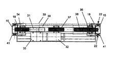
エレベータは多数の人員を運ぶのに適したケージ1を含んで構成され、そのケージは扉2を備え、形材3を組み立てた枠4によって補強されており、枠4はケージ1の扉2を備えている側面領域に配置されている。エレベータは快適な乗降ができるように各階に外部扉52及びバルコニー53を備えている。形材3は断面がU字状を呈し、ケージ1の高さ方向に延びたブリッジ5を有し、形材3の脚部6は外壁7に垂直に延びている。形材3の脚部6はアングル材9の脚部8と強固に連結されており、他方の脚部10は形材3と間隔をおいて延びており、ケージの反対側にU字状形材11を保持している。U字状形材11には、垂直なガイドレール12と共動するローラ13が設置され且つケーブル14の一端が固定されており、ケーブルの他端はカウンタウェイト15に連結している。断面がT字状のガイドレール12は、保持形材16を介して、断面がH字状の垂直梁18のブリッジ17に連結しており、垂直梁18のブリッジ17に平行に延びているガイドレール12の脚19は、締付爪20により垂直梁18に溶接された保持形材16に固定されている。ケージ1の方向を示しているガイドレール12のブリッジ21の長く延びた平行な面はローラ13間を通っている。このような構成をケージ1の両側に備えているので、垂直方向のみに自由度があることになる。
The elevator is configured to include a
カウンタウェイト15を垂直梁18のガイドレール12とは反対側のU字状凹部23に配置できるように、案内手段22を備え、案内手段22は垂直梁18の互いに向き合ったフランジ24に固定しているアングル材25並びにカウンタウェイト15に配置した案内ローラ26を含んで構成されている。垂直梁18のフランジ24に固定されたアングル材25の中央に備えた角はカウンタウェイト15の方向を示している。案内ローラ26はその円周面28がアングル材25の脚29上を回転するように配列されている。
Guide means 22 is provided so that the
伝道装置33を介してモータ32により駆動される駆動輪31を載置している水平梁30は、2つの垂直梁18の上端に嵌合している。ケージ1の左側に配置したケーブル14は、カウンタウェイト15から、第一の方向転換輪34、駆動輪31並びに駆動輪31の下方にあり第一の方向転換輪34に配置した第二の方向転換輪35を通って、U字状形材11まで達してそれに固定されている。エレベータの搬送力に応じて複数のケーブル14をこのように巡らすことが可能なことは明らかである。本発明においては、互いに平行して3本のケーブル14を備えている。ケージ1の右側のケーブル14は、それに割当てたカウンタウェイト15から第三の方向転換輪36達し、そこから駆動輪31並びにその下流に挿入した第四の方向転換輪37及び第五の方向転換輪38を経て、ケージの側方の固定位置に達している。ケーブル14が駆動輪31を所定の角度で囲み、一つの方向転換輪がケーブル14の滑りを防ぎ、他の方向転換輪がケージ1を一様に駆動するように、駆動輪31に対する方向転換輪34、35、36、37、38を決める。
The
風雨、特に湿度に対して防護するため、水平梁30上にエレベータの駆動部40を覆うカバー39を配置している。カバー39はケージ1の両側においてケース41に連結している。そのケースはケーブル14を通し且つ垂直梁18並びにガイドレール12及びカウンタウェイト15も収納し、垂直梁18の全高まで延びている。更に、枠4の形材3を保持するため、ケージ1の両側にケージより高く延びている保護ケースを備えている。ケージ1をガイドレール12と連結するため、保護ケース42は枠4の形材3に配置したアングル材9の脚部8が通る開口部43を備え、その脚部はケース41の空隙44を貫通している。開口部43は保護ケース42の2つの突出部45間に形成され、その形状は楕円であり長径はケージ1の高さ方向に沿っている。2つの突出部45はケース41の空隙44を貫通している。気密を保つため、ケース41の空隙44の両側の保護ケース42の突出部45に接して互いにV字状を成すシール片46を備えている。開口部43が楕円形のためシール片46はそれぞれが開口部43の上部及び下部を構成するか又は突出部45の形状に沿うので、ケース41並びに保護ケース42への水の侵入を効果的に防止する。
In order to protect against wind and rain, particularly humidity, a
ケージ1内の電気設備への電源の供給及びエレベータを制御するためにケージ1の左側に備えたケース41内に電気ケーブル47が配置されている。電気ケーブル47は、最初の水平梁30から別の水平梁へ、そしてケース41の空隙44並び保護ケース42の開口部43を通ってケージ1へと導かれる。ケージ1の右側には、既知の方法によりガイドレール12に作用する安全装置48の伸長ケーブルを備えている。
An
垂直梁18と共動する安全装置48を解放するため、一端が対応するカウンタウェイト15且つ他端がケージ1の床側に固定したワイヤケーブル49がケージ1の両側に備えられている。ワイヤケーブル49は対応する垂直梁18の下を通って、エレベータシャフトのピットへ導かれている。このワイヤケーブルは対応する伸長錘51を有する方向変換輪50を保持している。
In order to release the
1 ケージ
2 扉
3 形材
4 枠
5 ブリッジ
6 脚部
7 外壁
8 脚部
9 アングル材
10 脚部
11 U字状形材
12 ガイドレール
13 ローラ
14 ケーブル
15 カウンタウェイト
16 保持形材
17 ブリッジ
18 垂直梁
19 脚
20 締付爪
21 ブリッジ
22 案内手段
23 U字状凹部
24 フランジ
25 アングル材
26 案内ローラ
27 締付爪
28 円周面
29 脚
30 水平梁
31 駆動輪
32 モータ
33 伝道装置
34、35、36、37、38 方向転換輪
39 カバー
40 駆動部
41 ケース
42 保護ケース
43 開口部
44 空隙
45 突出部
46 シール片
47 電気ケーブル
48 安全装置
49 ワイヤケーブル
50 方向転換輪
51 伸長錘
52 外部扉
53 バルコニー
DESCRIPTION OF
Claims (23)
ケージ(1)の両側に、断面がH字状の垂直梁(18)を備え、
それぞれの垂直梁(18)は、ケージを向いた側にガイドレール(12)が固定されたケージに平行に配列されたブリッジ(17)、並びにケージ(1)とは逆を向いた側に一端がケージ(1)に他端がカウンタウェイト(15)に連結されたケーブル(14)を通すU字状凹部(23)を備え、
ケージ(1)は、ガイドレール(12)に接するローラ(13)を備え、
ケーブル(14)がケージ(1)の両側の各々のケース(41)内に配置された共通の駆動輪(31)により駆動されることを特徴とするエレベータ。An elevator having a cable driven cage (1),
Provided on both sides of the cage (1) with vertical beams (18) having an H -shaped cross section ,
Each vertical beam (18) has a bridge (17) arranged in parallel to the cage with a guide rail (12) fixed on the side facing the cage, and one end on the side facing away from the cage (1). Has a U-shaped recess (23) through which the cable (14) having the other end connected to the counterweight (15) is passed through the cage (1),
The cage (1) includes a roller (13) in contact with the guide rail (12),
An elevator characterized in that the cable (14) is driven by a common drive wheel (31) arranged in each case (41) on both sides of the cage (1).
Applications Claiming Priority (3)
| Application Number | Priority Date | Filing Date | Title |
|---|---|---|---|
| DE10325937A DE10325937B4 (en) | 2003-06-07 | 2003-06-07 | Elevator with a rope-driven cabin |
| DE10325937.6 | 2003-06-07 | ||
| PCT/DE2004/001157 WO2004110914A1 (en) | 2003-06-07 | 2004-06-04 | Lift with a cable-driven cabin |
Publications (2)
| Publication Number | Publication Date |
|---|---|
| JP2006527149A JP2006527149A (en) | 2006-11-30 |
| JP4786532B2 true JP4786532B2 (en) | 2011-10-05 |
Family
ID=33494897
Family Applications (1)
| Application Number | Title | Priority Date | Filing Date |
|---|---|---|---|
| JP2006515668A Expired - Fee Related JP4786532B2 (en) | 2003-06-07 | 2004-06-04 | Elevator with cable-driven cage |
Country Status (10)
| Country | Link |
|---|---|
| US (1) | US7374022B2 (en) |
| EP (1) | EP1641700B1 (en) |
| JP (1) | JP4786532B2 (en) |
| CN (1) | CN1829652A (en) |
| AT (1) | ATE362893T1 (en) |
| AU (1) | AU2004247314B2 (en) |
| CA (1) | CA2528319C (en) |
| DE (2) | DE10325937B4 (en) |
| ES (1) | ES2287737T3 (en) |
| WO (1) | WO2004110914A1 (en) |
Families Citing this family (4)
| Publication number | Priority date | Publication date | Assignee | Title |
|---|---|---|---|---|
| DE102005044978A1 (en) * | 2005-09-20 | 2007-04-19 | Repower Systems Ag | Lattice tower for transport of people and subjects, has driving system with travel cabin, control device and driving device whereby control device is designed closed to window so motion of control device is made relative to travel cabin |
| US20090032340A1 (en) * | 2007-07-31 | 2009-02-05 | Rory Smith | Method and Apparatus to Minimize Re-Leveling in High Rise High Speed Elevators |
| WO2010063650A1 (en) | 2008-12-04 | 2010-06-10 | Inventio Ag | Method for releasing a load receiving means or a compensating weight of a lift from a stopping position |
| CN111392536B (en) * | 2020-04-16 | 2023-05-23 | 施密特电梯有限公司 | Multifunctional communication type automatic calling elevator |
Citations (7)
| Publication number | Priority date | Publication date | Assignee | Title |
|---|---|---|---|---|
| US1782671A (en) * | 1929-05-13 | 1930-11-25 | Jr William P Allred | Storage and parking garage |
| JPS506123Y1 (en) * | 1970-10-14 | 1975-02-21 | ||
| JPH0419571U (en) * | 1990-06-11 | 1992-02-19 | ||
| JPH04138079U (en) * | 1991-06-19 | 1992-12-24 | 大宮木材工業株式会社 | outdoor elevator |
| JPH0725565A (en) * | 1993-07-14 | 1995-01-27 | Takenaka Komuten Co Ltd | Observation elevator device |
| JP2000344307A (en) * | 1999-03-05 | 2000-12-12 | Nippon Yusoki Co Ltd | Hang-up device |
| JP2002173279A (en) * | 2000-12-08 | 2002-06-21 | Toshiba Corp | Elevator |
Family Cites Families (11)
| Publication number | Priority date | Publication date | Assignee | Title |
|---|---|---|---|---|
| US1566491A (en) * | 1925-12-22 | lindquist | ||
| US2088690A (en) * | 1935-08-14 | 1937-08-03 | Inclinator Company Of America | Elevator |
| US3517774A (en) * | 1968-01-17 | 1970-06-30 | Roy E Meyer | Tower elevator |
| US4469198A (en) * | 1982-04-16 | 1984-09-04 | Crump Robert F | Outside rescue elevator system for high-rise buildings |
| JPS5974884A (en) | 1982-10-19 | 1984-04-27 | 三菱電機株式会社 | Elevator for view |
| US4592270A (en) * | 1984-07-16 | 1986-06-03 | Vener Alvin S | Smoke and fire protection system for elevators |
| DE3818856A1 (en) | 1988-06-03 | 1989-12-07 | Francois Remlinger | Passenger lift for two-storey dwelling houses |
| US5355976A (en) * | 1992-07-31 | 1994-10-18 | Daifuku Co., Ltd. | Handling apparatus for automatic warehousing arrangement |
| EP2042462B1 (en) * | 2000-09-12 | 2011-05-18 | Mitsubishi Denki Kabushiki Kaisha | Elevator apparatus |
| DE10212268A1 (en) | 2001-03-24 | 2003-01-23 | Wolfgang T Mueller | Modular-style lift with no machine chamber has integrated front with two columns extending from bottom to top of lift shaft either side of door opening and guiding at least one counter weight |
| DE20310731U1 (en) | 2003-06-07 | 2003-09-11 | Schmitt Aufzüge GmbH, 55218 Ingelheim | Lift with cable-driven cage for people or goods has vertical H-section guide rails with lift cage moving between rails and counterweights moving on sides of rails away from cage |
-
2003
- 2003-06-07 DE DE10325937A patent/DE10325937B4/en not_active Expired - Fee Related
-
2004
- 2004-06-04 AU AU2004247314A patent/AU2004247314B2/en not_active Ceased
- 2004-06-04 DE DE502004003892T patent/DE502004003892D1/en not_active Expired - Lifetime
- 2004-06-04 EP EP04738611A patent/EP1641700B1/en not_active Expired - Lifetime
- 2004-06-04 WO PCT/DE2004/001157 patent/WO2004110914A1/en active IP Right Grant
- 2004-06-04 ES ES04738611T patent/ES2287737T3/en not_active Expired - Lifetime
- 2004-06-04 JP JP2006515668A patent/JP4786532B2/en not_active Expired - Fee Related
- 2004-06-04 CN CNA2004800218701A patent/CN1829652A/en active Pending
- 2004-06-04 CA CA2528319A patent/CA2528319C/en not_active Expired - Fee Related
- 2004-06-04 AT AT04738611T patent/ATE362893T1/en active
- 2004-06-04 US US10/559,771 patent/US7374022B2/en not_active Expired - Fee Related
Patent Citations (7)
| Publication number | Priority date | Publication date | Assignee | Title |
|---|---|---|---|---|
| US1782671A (en) * | 1929-05-13 | 1930-11-25 | Jr William P Allred | Storage and parking garage |
| JPS506123Y1 (en) * | 1970-10-14 | 1975-02-21 | ||
| JPH0419571U (en) * | 1990-06-11 | 1992-02-19 | ||
| JPH04138079U (en) * | 1991-06-19 | 1992-12-24 | 大宮木材工業株式会社 | outdoor elevator |
| JPH0725565A (en) * | 1993-07-14 | 1995-01-27 | Takenaka Komuten Co Ltd | Observation elevator device |
| JP2000344307A (en) * | 1999-03-05 | 2000-12-12 | Nippon Yusoki Co Ltd | Hang-up device |
| JP2002173279A (en) * | 2000-12-08 | 2002-06-21 | Toshiba Corp | Elevator |
Also Published As
| Publication number | Publication date |
|---|---|
| JP2006527149A (en) | 2006-11-30 |
| EP1641700B1 (en) | 2007-05-23 |
| CA2528319A1 (en) | 2004-12-23 |
| CA2528319C (en) | 2012-01-10 |
| WO2004110914A1 (en) | 2004-12-23 |
| AU2004247314B2 (en) | 2009-01-15 |
| CN1829652A (en) | 2006-09-06 |
| DE10325937B4 (en) | 2005-06-23 |
| US20060254863A1 (en) | 2006-11-16 |
| AU2004247314A1 (en) | 2004-12-23 |
| DE10325937A1 (en) | 2005-01-05 |
| ATE362893T1 (en) | 2007-06-15 |
| US7374022B2 (en) | 2008-05-20 |
| DE502004003892D1 (en) | 2007-07-05 |
| EP1641700A1 (en) | 2006-04-05 |
| ES2287737T3 (en) | 2007-12-16 |
Similar Documents
| Publication | Publication Date | Title |
|---|---|---|
| RU2482051C2 (en) | Elevator shaft carcass | |
| US6691833B1 (en) | Elevator without a machine room | |
| JP3014952B2 (en) | Traction sheave elevator | |
| KR100302557B1 (en) | Control system of elevator | |
| US6782975B1 (en) | Pre-assembled elevator shaft | |
| JP4786532B2 (en) | Elevator with cable-driven cage | |
| KR100950991B1 (en) | Traction machine structure for an elevator and cage assembly | |
| US20180327228A1 (en) | Tensioning arrangement for an elevator | |
| PL192954B1 (en) | Lift in particular that with a traction rope pulley | |
| KR100941955B1 (en) | Traction machine structure for an elevator and cage assembly | |
| US20040035647A1 (en) | Elevator car frame with integral controller | |
| JPH01267286A (en) | Home elevator | |
| JP4189382B2 (en) | Rooftop control unit for elevator system with removable cover | |
| AU2010214698A1 (en) | A residential lift | |
| KR100964722B1 (en) | Traction machine structure for an elevator and cage assembly | |
| JP2000007253A (en) | Small sized elevator device | |
| JP2001072351A (en) | elevator | |
| KR19990027217A (en) | Elevator with hoist and control panel arranged in pit of hoistway | |
| KR100923274B1 (en) | Elevator hoisting structure and cage assembly | |
| JP2003155180A (en) | Elevator and its assembling method | |
| KR20100110704A (en) | Traction machine structure for an elevator and cage assembly | |
| JP2002321887A (en) | Installing structure for control panel of elevator and installing structure for safety fence | |
| JP2005206386A (en) | Elevator system |
Legal Events
| Date | Code | Title | Description |
|---|---|---|---|
| A621 | Written request for application examination |
Free format text: JAPANESE INTERMEDIATE CODE: A621 Effective date: 20070524 |
|
| A977 | Report on retrieval |
Free format text: JAPANESE INTERMEDIATE CODE: A971007 Effective date: 20100825 |
|
| A131 | Notification of reasons for refusal |
Free format text: JAPANESE INTERMEDIATE CODE: A131 Effective date: 20100914 |
|
| A521 | Request for written amendment filed |
Free format text: JAPANESE INTERMEDIATE CODE: A523 Effective date: 20101213 |
|
| A131 | Notification of reasons for refusal |
Free format text: JAPANESE INTERMEDIATE CODE: A131 Effective date: 20110308 |
|
| A521 | Request for written amendment filed |
Free format text: JAPANESE INTERMEDIATE CODE: A523 Effective date: 20110310 |
|
| TRDD | Decision of grant or rejection written | ||
| A01 | Written decision to grant a patent or to grant a registration (utility model) |
Free format text: JAPANESE INTERMEDIATE CODE: A01 Effective date: 20110614 |
|
| A01 | Written decision to grant a patent or to grant a registration (utility model) |
Free format text: JAPANESE INTERMEDIATE CODE: A01 |
|
| A61 | First payment of annual fees (during grant procedure) |
Free format text: JAPANESE INTERMEDIATE CODE: A61 Effective date: 20110713 |
|
| R150 | Certificate of patent or registration of utility model |
Free format text: JAPANESE INTERMEDIATE CODE: R150 |
|
| FPAY | Renewal fee payment (event date is renewal date of database) |
Free format text: PAYMENT UNTIL: 20140722 Year of fee payment: 3 |
|
| LAPS | Cancellation because of no payment of annual fees |