JP4775287B2 - Heat exchanger - Google Patents
Heat exchanger Download PDFInfo
- Publication number
- JP4775287B2 JP4775287B2 JP2007054631A JP2007054631A JP4775287B2 JP 4775287 B2 JP4775287 B2 JP 4775287B2 JP 2007054631 A JP2007054631 A JP 2007054631A JP 2007054631 A JP2007054631 A JP 2007054631A JP 4775287 B2 JP4775287 B2 JP 4775287B2
- Authority
- JP
- Japan
- Prior art keywords
- tube
- fluid
- casing
- heat exchanger
- tubes
- Prior art date
- Legal status (The legal status is an assumption and is not a legal conclusion. Google has not performed a legal analysis and makes no representation as to the accuracy of the status listed.)
- Expired - Fee Related
Links
Images


Classifications
-
- F—MECHANICAL ENGINEERING; LIGHTING; HEATING; WEAPONS; BLASTING
- F28—HEAT EXCHANGE IN GENERAL
- F28D—HEAT-EXCHANGE APPARATUS, NOT PROVIDED FOR IN ANOTHER SUBCLASS, IN WHICH THE HEAT-EXCHANGE MEDIA DO NOT COME INTO DIRECT CONTACT
- F28D9/00—Heat-exchange apparatus having stationary plate-like or laminated conduit assemblies for both heat-exchange media, the media being in contact with different sides of a conduit wall
- F28D9/0031—Heat-exchange apparatus having stationary plate-like or laminated conduit assemblies for both heat-exchange media, the media being in contact with different sides of a conduit wall the conduits for one heat-exchange medium being formed by paired plates touching each other
-
- F—MECHANICAL ENGINEERING; LIGHTING; HEATING; WEAPONS; BLASTING
- F02—COMBUSTION ENGINES; HOT-GAS OR COMBUSTION-PRODUCT ENGINE PLANTS
- F02M—SUPPLYING COMBUSTION ENGINES IN GENERAL WITH COMBUSTIBLE MIXTURES OR CONSTITUENTS THEREOF
- F02M26/00—Engine-pertinent apparatus for adding exhaust gases to combustion-air, main fuel or fuel-air mixture, e.g. by exhaust gas recirculation [EGR] systems
- F02M26/11—Manufacture or assembly of EGR systems; Materials or coatings specially adapted for EGR systems
-
- F—MECHANICAL ENGINEERING; LIGHTING; HEATING; WEAPONS; BLASTING
- F02—COMBUSTION ENGINES; HOT-GAS OR COMBUSTION-PRODUCT ENGINE PLANTS
- F02M—SUPPLYING COMBUSTION ENGINES IN GENERAL WITH COMBUSTIBLE MIXTURES OR CONSTITUENTS THEREOF
- F02M26/00—Engine-pertinent apparatus for adding exhaust gases to combustion-air, main fuel or fuel-air mixture, e.g. by exhaust gas recirculation [EGR] systems
- F02M26/13—Arrangement or layout of EGR passages, e.g. in relation to specific engine parts or for incorporation of accessories
- F02M26/22—Arrangement or layout of EGR passages, e.g. in relation to specific engine parts or for incorporation of accessories with coolers in the recirculation passage
- F02M26/23—Layout, e.g. schematics
- F02M26/25—Layout, e.g. schematics with coolers having bypasses
-
- F—MECHANICAL ENGINEERING; LIGHTING; HEATING; WEAPONS; BLASTING
- F02—COMBUSTION ENGINES; HOT-GAS OR COMBUSTION-PRODUCT ENGINE PLANTS
- F02M—SUPPLYING COMBUSTION ENGINES IN GENERAL WITH COMBUSTIBLE MIXTURES OR CONSTITUENTS THEREOF
- F02M26/00—Engine-pertinent apparatus for adding exhaust gases to combustion-air, main fuel or fuel-air mixture, e.g. by exhaust gas recirculation [EGR] systems
- F02M26/13—Arrangement or layout of EGR passages, e.g. in relation to specific engine parts or for incorporation of accessories
- F02M26/22—Arrangement or layout of EGR passages, e.g. in relation to specific engine parts or for incorporation of accessories with coolers in the recirculation passage
- F02M26/29—Constructional details of the coolers, e.g. pipes, plates, ribs, insulation or materials
- F02M26/32—Liquid-cooled heat exchangers
-
- F—MECHANICAL ENGINEERING; LIGHTING; HEATING; WEAPONS; BLASTING
- F28—HEAT EXCHANGE IN GENERAL
- F28D—HEAT-EXCHANGE APPARATUS, NOT PROVIDED FOR IN ANOTHER SUBCLASS, IN WHICH THE HEAT-EXCHANGE MEDIA DO NOT COME INTO DIRECT CONTACT
- F28D7/00—Heat-exchange apparatus having stationary tubular conduit assemblies for both heat-exchange media, the media being in contact with different sides of a conduit wall
- F28D7/16—Heat-exchange apparatus having stationary tubular conduit assemblies for both heat-exchange media, the media being in contact with different sides of a conduit wall the conduits being arranged in parallel spaced relation
- F28D7/1684—Heat-exchange apparatus having stationary tubular conduit assemblies for both heat-exchange media, the media being in contact with different sides of a conduit wall the conduits being arranged in parallel spaced relation the conduits having a non-circular cross-section
-
- F—MECHANICAL ENGINEERING; LIGHTING; HEATING; WEAPONS; BLASTING
- F28—HEAT EXCHANGE IN GENERAL
- F28D—HEAT-EXCHANGE APPARATUS, NOT PROVIDED FOR IN ANOTHER SUBCLASS, IN WHICH THE HEAT-EXCHANGE MEDIA DO NOT COME INTO DIRECT CONTACT
- F28D9/00—Heat-exchange apparatus having stationary plate-like or laminated conduit assemblies for both heat-exchange media, the media being in contact with different sides of a conduit wall
- F28D9/0025—Heat-exchange apparatus having stationary plate-like or laminated conduit assemblies for both heat-exchange media, the media being in contact with different sides of a conduit wall the conduits being formed by zig-zag bend plates
-
- F—MECHANICAL ENGINEERING; LIGHTING; HEATING; WEAPONS; BLASTING
- F28—HEAT EXCHANGE IN GENERAL
- F28F—DETAILS OF HEAT-EXCHANGE AND HEAT-TRANSFER APPARATUS, OF GENERAL APPLICATION
- F28F3/00—Plate-like or laminated elements; Assemblies of plate-like or laminated elements
- F28F3/02—Elements or assemblies thereof with means for increasing heat-transfer area, e.g. with fins, with recesses, with corrugations
- F28F3/04—Elements or assemblies thereof with means for increasing heat-transfer area, e.g. with fins, with recesses, with corrugations the means being integral with the element
- F28F3/042—Elements or assemblies thereof with means for increasing heat-transfer area, e.g. with fins, with recesses, with corrugations the means being integral with the element in the form of local deformations of the element
- F28F3/044—Elements or assemblies thereof with means for increasing heat-transfer area, e.g. with fins, with recesses, with corrugations the means being integral with the element in the form of local deformations of the element the deformations being pontual, e.g. dimples
-
- F—MECHANICAL ENGINEERING; LIGHTING; HEATING; WEAPONS; BLASTING
- F28—HEAT EXCHANGE IN GENERAL
- F28F—DETAILS OF HEAT-EXCHANGE AND HEAT-TRANSFER APPARATUS, OF GENERAL APPLICATION
- F28F9/00—Casings; Header boxes; Auxiliary supports for elements; Auxiliary members within casings
-
- F—MECHANICAL ENGINEERING; LIGHTING; HEATING; WEAPONS; BLASTING
- F28—HEAT EXCHANGE IN GENERAL
- F28D—HEAT-EXCHANGE APPARATUS, NOT PROVIDED FOR IN ANOTHER SUBCLASS, IN WHICH THE HEAT-EXCHANGE MEDIA DO NOT COME INTO DIRECT CONTACT
- F28D21/00—Heat-exchange apparatus not covered by any of the groups F28D1/00 - F28D20/00
- F28D21/0001—Recuperative heat exchangers
- F28D21/0003—Recuperative heat exchangers the heat being recuperated from exhaust gases
-
- F—MECHANICAL ENGINEERING; LIGHTING; HEATING; WEAPONS; BLASTING
- F28—HEAT EXCHANGE IN GENERAL
- F28F—DETAILS OF HEAT-EXCHANGE AND HEAT-TRANSFER APPARATUS, OF GENERAL APPLICATION
- F28F2240/00—Spacing means
-
- F—MECHANICAL ENGINEERING; LIGHTING; HEATING; WEAPONS; BLASTING
- F28—HEAT EXCHANGE IN GENERAL
- F28F—DETAILS OF HEAT-EXCHANGE AND HEAT-TRANSFER APPARATUS, OF GENERAL APPLICATION
- F28F2250/00—Arrangements for modifying the flow of the heat exchange media, e.g. flow guiding means; Particular flow patterns
- F28F2250/06—Derivation channels, e.g. bypass
Landscapes
- Engineering & Computer Science (AREA)
- Mechanical Engineering (AREA)
- General Engineering & Computer Science (AREA)
- Physics & Mathematics (AREA)
- Thermal Sciences (AREA)
- Chemical & Material Sciences (AREA)
- Combustion & Propulsion (AREA)
- Manufacturing & Machinery (AREA)
- Exhaust-Gas Circulating Devices (AREA)
- Heat-Exchange Devices With Radiators And Conduit Assemblies (AREA)
Abstract
Description
本発明は2種類の流体間において熱交換せしめる熱交換器に関するものであり、たとえば、内燃機関に備えられるEGR(排気再循環)システムを構成する一要素である内燃機関の燃焼により発生した排気ガスと冷却水との間で熱交換を行う排気熱交換器として用いて好適な熱交換器に関するものである。 The present invention relates to a heat exchanger for exchanging heat between two kinds of fluids, for example, exhaust gas generated by combustion of an internal combustion engine that is one element constituting an EGR (exhaust gas recirculation) system provided in the internal combustion engine. The present invention relates to a heat exchanger suitable for use as an exhaust heat exchanger for exchanging heat between water and cooling water.
従来の熱交換器として、たとえば、EGRシステム(排気再循環システム)においてエンジンから排出される排気ガスの一部をエンジンの吸気側に循環させる際に、この排気ガスを冷却水によって冷却する排気熱交換器がある(特許文献1参照)。 As a conventional heat exchanger, for example, when part of exhaust gas discharged from the engine is circulated to the intake side of the engine in an EGR system (exhaust gas recirculation system), the exhaust heat is cooled by cooling water. There is an exchanger (see Patent Document 1).
EGRを行うことにより排気ガス中の窒素酸化物(NOx)量を確実に低減させることができ、EGRガスを予め冷却して温度を下げてからエンジンの吸気側に循環させることでNOx低減効果を一層高めることができる。しかしながら、単純にEGRガスを再循環させるだけでは、エンジンの運転条件によっては排気微粒子(パティキュレート・マター、以下PMと呼ぶ)、HC(ハイドロ・カーボン)の排出量が増大する場合がある。すなわち、エンジンの運転条件に応じて、最適なEGRガス温度、つまりNOxの排出量だけでなくPMの排出量をも同時に低減できるようなEGRガス温度が存在する。そこで、特許文献1に示される排気熱交換器は、エンジン冷却水によりEGRガスを冷却するEGR冷却通路と、周囲が空気層でEGRガスが冷却されないバイパス通路とを平行且つ一体的に備え、排気熱交換器と直列に配置された切り替えバルブにより両通路を通過するEGRガス流量を調節することにより、EGRガス温度を最適値に制御可能としている。 By performing EGR, the amount of nitrogen oxide (NOx) in the exhaust gas can be reliably reduced, and the EGR gas is cooled in advance to lower the temperature and then circulated to the intake side of the engine, thereby reducing NOx. It can be further enhanced. However, simply recirculating the EGR gas may increase exhaust particulate matter (particulate matter, hereinafter referred to as PM) and HC (hydrocarbon) depending on engine operating conditions. That is, there exists an EGR gas temperature that can reduce not only the optimum EGR gas temperature, that is, the NOx emission amount but also the PM emission amount at the same time, according to the engine operating conditions. Therefore, the exhaust heat exchanger disclosed in Patent Document 1 includes an EGR cooling passage that cools the EGR gas with engine cooling water and a bypass passage that is surrounded by an air layer and is not cooled by the EGR gas in parallel and integrally. The EGR gas temperature can be controlled to an optimum value by adjusting the flow rate of the EGR gas passing through both passages by a switching valve arranged in series with the heat exchanger.
上述の排気熱交換器は、内部を第1流体であるEGRガスが流れる複数積層されたチューブが筒状のケーシング内部に収容されて、ケーシングの長手方向の両端部に排気熱交換器をEGRガス通路に接続するためのボンネットが接続されている。また、ケーシング内部には、EGR冷却通路を構成するチューブとバイパス通路を構成するチューブとの間に仕切り板が設けられて、ケーシング内部は2つの空間に分離されている。すばわち、2つの空間の内、EGR冷却通路を構成するチューブが内包される空間にはエンジン冷却水が導入され、チューブを介してEGRガスとエンジン冷却水との間で熱交換が行われる。一方、バイパス通路を構成するチューブが内包される空間にはエンジン冷却水に代わりに空気が封入され、つまりチューブの外周には空気層が形成され、EGRガスがバイパス通路を通過する際に温度低下はほとんどない。
ところで、上記の従来の排気熱交換器は、ケーシング内に、EGR冷却通路とバイパス通路とを分離する隔壁である仕切り板を設ける構成するとしている。このため、仕切り板をケーシング内壁全周に完全に密着固定する必要があり、組付け工数、部品点数が増加するという問題がある。 By the way, the above-described conventional exhaust heat exchanger has a configuration in which a partition plate, which is a partition separating the EGR cooling passage and the bypass passage, is provided in the casing. For this reason, it is necessary to closely fix the partition plate to the entire inner wall of the casing, and there is a problem that the number of assembling steps and the number of parts increase.
本発明は、上記問題に鑑みなされたものであり、一体的に備えた冷却通路とバイパス通路とを仕切り板を用いない容易な手段によって隔離可能な熱交換器を提供することを目的とする。 The present invention has been made in view of the above problems, and an object of the present invention is to provide a heat exchanger capable of isolating an integrally provided cooling passage and bypass passage by an easy means that does not use a partition plate.
本発明は上記目的を達成するために、以下の技術的手段を採用する。 In order to achieve the above object, the present invention employs the following technical means.
本発明の請求項1に記載の発明では、積層配置され、内部を第1流体が通過する複数本の偏平状の第1チューブ(210)からなる第1チューブ群と、積層方向において最外側に配される第1チューブの外側に積層配置され、内部を第1流体が通過する第2チューブ(270)と、第1チューブ群と第2チューブ(270)とを内部に納めたケーシング(230)と、ケーシングの内部に形成され、第1チューブ群が配され、第1チューブ群を通過する第1流体と熱交換する第2流体が通過する第2流体通路と、ケーシングの内部に第2チューブ(270)が配され、第2チューブの周囲に断熱空間を形成するバイパス通路と、チューブの端部と連通し、複数のチューブへと第1流体を分配する、または複数のチューブを通過した第1流体を集める接続フランジと、チューブの端部が挿通され、ケーシングの内部と接続フランジとを区画するコアプレートとを有する熱交換器であって、ケーシングは、第1のチューブ(210)の断面長手方向よりも膨出し、第2流体通路の一部をなす第1の膨出部と、積層方向において第2チューブ(270)に隣接して配される第1チューブ(210)の断面長手方向の端面と当接することにより、前記第2流体通路(215)と前記断熱空間(219)とを区画する区画壁面(232)と、を有することを特徴としている。 In the invention according to claim 1 of the present invention, a first tube group comprising a plurality of flat first tubes (210) arranged in a stack and through which the first fluid passes, and on the outermost side in the stacking direction. A casing (230) that is stacked on the outside of the arranged first tube and that houses the second tube (270) through which the first fluid passes, and the first tube group and the second tube (270). And a second fluid passage formed in the casing, in which a first tube group is arranged, a second fluid that exchanges heat with the first fluid that passes through the first tube group, and a second tube in the casing. (270) is disposed, communicates with a bypass passage that forms a heat insulation space around the second tube, and an end of the tube, distributes the first fluid to the plurality of tubes, or passes through the plurality of tubes. 1 fluid A heat exchanger having a connecting flange and a core plate through which an end portion of the tube is inserted to partition the inside of the casing and the connecting flange, wherein the casing is in the longitudinal direction of the cross section of the first tube (210) A first bulging portion that bulges further and forms part of the second fluid passage, and an end face in the longitudinal direction of the cross section of the first tube (210) disposed adjacent to the second tube (270) in the stacking direction and by contact, it is characterized by having a compartment wall surface (232) for partitioning the said insulation space second fluid passage and (215) (219).
上述の構成によれば、従来の熱交換器における仕切り板を設けること無しに、第1流体と第2流体との間で熱交換が行われる第2流体通路と、第1流体と第2流体との間で熱交換が行われないバイパス通路とを隔離可能な熱交換器を提供することができる。 According to the above configuration, the second fluid passage in which heat is exchanged between the first fluid and the second fluid without providing the partition plate in the conventional heat exchanger, and the first fluid and the second fluid. It is possible to provide a heat exchanger that can isolate a bypass passage from which heat exchange is not performed.
本発明の請求項2に記載の発明では、ケーシングに接続され、第2流体を第2流体通路に流入させる流入管と、ケーシングに接続され、第2流体を第2流体通路から流出させる流出管とを有し、膨出部は流入管及び流出管の接続部位に形成されていることを特徴としている。これにより、流入管、流出管および第1の膨出部を介して第2流体通路内に、確実に第2流体を流通させることができる。 According to the second aspect of the present invention, the inflow pipe is connected to the casing and allows the second fluid to flow into the second fluid passage, and the outflow pipe is connected to the casing and allows the second fluid to flow out of the second fluid path. The bulging part is formed in the connection site | part of an inflow pipe and an outflow pipe, It is characterized by the above-mentioned. Thereby, a 2nd fluid can be reliably distribute | circulated in a 2nd fluid channel | path via an inflow pipe, an outflow pipe, and a 1st bulging part.
本発明の請求項3に記載の発明では、ケーシングに接続され、第2流体を前記第2流体通路から流出させる流出管を有し、流出管がケーシングに接続される接続部位には第1膨出部よりも内容積が大きい第2膨出部が形成されていることを特徴としている。 According to a third aspect of the present invention, there is provided an outflow pipe connected to the casing and allowing the second fluid to flow out of the second fluid passage, and the connection portion where the outflow pipe is connected to the casing has a first expansion. A second bulging portion having a larger internal volume than the protruding portion is formed.
熱交換器にいて、第2流体の流れる経路は、流入管、第1膨出部、第2流体通路、第2膨出部、流出管となっている。ここで、第2流体通路の出口側に位置する第2膨出部の内容積を第1膨出部のない容積よりも大きくすると、第2流体通路の背圧をより下げる効果が得られ、それにより、第2流体を第2流体通路中をスムーズに流すことができる。言い換えると、第1流体と第2流体との熱交換効率を高めることができる。 In the heat exchanger, the flow path of the second fluid is an inflow pipe, a first bulge portion, a second fluid passage, a second bulge portion, and an outflow pipe. Here, if the internal volume of the second bulging portion located on the outlet side of the second fluid passage is larger than the volume without the first bulging portion, an effect of lowering the back pressure of the second fluid passage is obtained, Thereby, the second fluid can flow smoothly in the second fluid passage. In other words, the heat exchange efficiency between the first fluid and the second fluid can be increased.
本発明の請求項4に記載の発明では、第1チューブ(210)の内部にインナーフィン(220)が配設されたことを特徴としている。 The invention according to claim 4 of the present invention is characterized in that the inner fin (220) is disposed inside the first tube (210).
これにより、第1流体に対して乱流効果を与えることができるので、熱交換性能を向上させることができる。 Thereby, since a turbulent flow effect can be given to the first fluid, the heat exchange performance can be improved.
請求項5に記載の発明では、扁平状断面を成し複数積層されるチューブ(110)内を流通する第1流体と前記チューブ(110)の外側を流通する第2流体との間で熱交換せしめる熱交換器であって、チューブ(110)が積層される際に互いに対向する対向面(111)の外周に形成されて外方へ突出する凸部(112)と、凸部(112)の対向面(111)の長辺側の2ヶ所以上に形成され且つ凸部(112)に対して凹状となる凹部(113)とを備え、複数のチューブ(110)は凸部(112)を互いに当接させて積層され、隣接する2つのチューブ(110)間において対向面(111)および凸部(112)に囲まれる空間が第2流体の流通する流路(115)となり、チューブ(110)の凹部(113)が形成される側の側面(118)に当接し且つ凹部(113)を包含するように接続板部材(132)が設けられ、接続板部材(132)は外側に張出すように形成された容積室(133)を備え、接続板部材(132)は、複数のチューブ(110)の積層方向における一端側に形成された凹部(113)を塞ぎ且つ残りの凹部(113)を容積室(133)に連通させて側面(118)に固定され、接続板部材(132)により塞がれた凹部(113)に連通する流路(115)は密閉され且つ空気が封入された断熱空間(119)を形成し、容積室(133)は外部の第2流体回路に接続されるジョイント部(141、142)を備え、ジョイント部(141、142)および容積室(133)を介して流路(115)内へ第2流体の流入、あるいは隙間内から第2流体が流出することを特徴としている。 In the invention according to claim 5, heat exchange is performed between the first fluid flowing in the tube (110) having a flat cross section and being stacked in plural and the second fluid flowing outside the tube (110). A heat exchanger, a convex portion (112) formed on the outer periphery of the opposing surface (111) facing each other when the tubes (110) are stacked, and a convex portion (112) projecting outward; The plurality of tubes (110) are formed at two or more locations on the long side of the opposing surface (111) and are concave with respect to the convex portion (112), and the plurality of tubes (110) have the convex portions (112) connected to each other. A space surrounded by the opposed surface (111) and the convex portion (112) between two adjacent tubes (110) that are in contact with each other becomes a flow path (115) through which the second fluid flows, and the tube (110). Recess (113) is formed The connecting plate member (132) is provided so as to abut on the side surface (118) and include the recess (113), and the connecting plate member (132) has a volume chamber (133) formed so as to project outward. The connecting plate member (132) closes the recess (113) formed on one end side in the stacking direction of the plurality of tubes (110), and communicates the remaining recess (113) with the volume chamber (133). The flow path (115) fixed to (118) and communicating with the recess (113) closed by the connecting plate member (132) forms a heat insulating space (119) that is sealed and enclosed with air, and is a volume chamber. (133) includes joint portions (141, 142) connected to an external second fluid circuit, and the second fluid enters the flow path (115) through the joint portions (141, 142) and the volume chamber (133). Inflow, or It is characterized in that the second fluid flows out of the gap.
上述の構成によれば、流路(115)に隣接するチューブ(110)内を流れる第1流体は、チューブ(110)を介して第2流体との間で熱交換が行われ、断熱空間(119)に挟まれたチューブ(110)内を流れる第1流体と第2流体とは熱交換せず、断熱空間(119)に挟まれたチューブ(110)を流れる第1流体の温度低下を抑制できる。 According to the above-described configuration, the first fluid flowing in the tube (110) adjacent to the flow path (115) undergoes heat exchange with the second fluid via the tube (110), so that the heat insulating space ( a first fluid flowing through the sandwiched tubing (110) to 119) without heat exchange with the second fluid, suppress the temperature drop of the first fluid flowing through the tube (110) sandwiched between the heat insulation space (119) I can .
また、凸部(112)によって第1流体と第2流体が流通する領域を区画することができるので、この熱交換器(100)において、従来技術の項で説明したコアプレートを廃止することができる。 Moreover, since the area | region where a 1st fluid and a 2nd fluid distribute | circulate can be divided by the convex part (112), in this heat exchanger (100), the core plate demonstrated in the term of the prior art is abolished. it can.
また、コアプレートを廃止できることから、チューブ(110)をコアプレートに挿通させるための組付け工数を不要とすることができ、総じて熱交換器(100)としてのコストを低減することができる。 Further, since the core plate can be eliminated, the assembly man-hour for inserting the tube (110) through the core plate can be eliminated, and the cost of the heat exchanger (100) can be reduced as a whole.
以上から、従来の熱交換器において第1流体と第2流体との間で熱交換が行われるチューブと第1流体と第2流体との間で熱交換が行われないチューブとを隔離している仕切り板を不要として、コアプレートを不要として、接続板部材に容積室を設けるという容易な手段の採用により、第1流体と第2流体との間で熱交換が行われる冷却通路と、第1流体と第2流体との間で熱交換が行われないバイパス通路とを隔離可能な熱交換器を提供することができる。 As described above, in the conventional heat exchanger, the tube in which heat exchange is performed between the first fluid and the second fluid and the tube in which heat exchange is not performed between the first fluid and the second fluid are isolated. A cooling passage in which heat is exchanged between the first fluid and the second fluid by adopting an easy means of eliminating the need for a partition plate, eliminating the need for a core plate, and providing a volume chamber in the connection plate member; It is possible to provide a heat exchanger capable of isolating a bypass passage where heat is not exchanged between the first fluid and the second fluid.
請求項6に記載の発明では、チューブ(110)の積層方向の両最外方となる2つの最外面(111a)の少なくとも一方には、凸部(112)、および凹部(113)が形成されており、2つの最外面(111a)の少なくとも一方の更に外方から凸部(112)に当接する外方板部材(131)が設けられたことを特徴としている。 In the invention according to claim 6, the convex portion (112) and the concave portion (113) are formed on at least one of the two outermost surfaces (111 a) which are both outermost in the stacking direction of the tube (110). In addition, an outer plate member (131) that comes into contact with the convex portion (112) from the outer side of at least one of the two outermost surfaces (111a) is provided.
これにより、最外面(111a)と外方板部材(131)との間にも流路(115)を形成して第2流体を流通させることができ、第1流体との熱交換面積を増加させて、熱交換性能を向上させることができる。 Thereby, a flow path (115) can also be formed between the outermost surface (111a) and the outer plate member (131) to circulate the second fluid, and the heat exchange area with the first fluid can be increased. Thus, heat exchange performance can be improved.
請求項7に記載の発明では、外方板部材(131)は、2つの最外面(111a)に設けられ、2つの外方板部材(131)は、対向面(111)の一方の長辺側で接続板部材(132)によって接続されてケーシング(130)を形成することを特徴としている。 In the invention according to claim 7, the outer plate member (131) is provided on the two outermost surfaces (111a), and the two outer plate members (131) are one of the long sides of the opposing surface (111). It is characterized in that it is connected on the side by a connecting plate member (132) to form a casing (130).
これにより、2つの外方板部材(131)をケーシング(130)として一体的に形成することができ、また、複数積層されたチューブ(110)に対して挟み込むようにして配設することが可能となり、組付けが容易となる。 As a result, the two outer plate members (131) can be integrally formed as a casing (130), and can be disposed so as to be sandwiched between a plurality of stacked tubes (110). Thus, assembly becomes easy.
請求項8に記載の発明では、凹部(113)のへこみ寸法は、対向面(111)に対する凸部(112)の突出寸法に等しくなるようにしたことを特徴としている。 The invention according to claim 8 is characterized in that the indentation dimension of the recess (113) is made equal to the projecting dimension of the projection (112) with respect to the opposing surface (111).
これにより、第2流体が流入・流出する際の開口面積を対向面(111)に向けて大きく設定できるので、第2流体の流通抵抗を小さくすることができる。 Thereby, since the opening area at the time of the 2nd fluid inflow / outflow can be set large toward the opposing surface (111), the distribution resistance of the 2nd fluid can be made small.
請求項9に記載の発明では、凹部(113)の形成される所定2ヶ所の位置は、対向面(111)において対角の位置となるようにしたことを特徴としている。 The invention according to claim 9 is characterized in that the two predetermined positions where the recesses (113) are formed are diagonal positions on the opposing surface (111).
これにより、チューブ(110)間の流路(115)において、第2流体が停滞する領域をできにくくすることができるので、熱交換性能を高めることができる。 Thereby, in the flow path (115) between the tubes (110), the region where the second fluid stagnates can be made difficult, so that the heat exchange performance can be improved.
請求項10に記載の発明では、対向面(111)の凸部(112)の内側領域には、第1流体流れ上流側に対応する部位において、第2流体の流れが流路(115)内の全体に拡がるように整流する整流手段(117)が形成されていることを特徴としている。
In the invention according to
これにより、第2流体の流通する流路(115)において、第1流体流れの上流側に対応する部位において第2流体流れの淀みの発生を抑制でき、第2流体の沸騰を防止することができる。 Thereby, in the flow path (115) through which the second fluid flows, generation of stagnation of the second fluid flow can be suppressed at a portion corresponding to the upstream side of the first fluid flow, and boiling of the second fluid can be prevented. it can.
請求項11に記載の発明では、チューブ(110)は、2枚の板部材(110a、110b)から形成されたことを特徴としている。 The invention according to claim 11 is characterized in that the tube (110) is formed of two plate members (110a, 110b).
これにより、丸管を形成した後に扁平状断面に成形するよりも、例えば曲げ加工、プレス加工、ロール加工等で板部材(110a、110b)を成形して組み合わせることで、容易に安価にチューブ(110)を成形することができる。 Thus, rather than forming a round tube after forming a round tube, the plate member (110a, 110b) can be formed and combined by, for example, bending, pressing, roll processing, etc., so that the tube ( 110).
請求項12に記載の発明では、チューブ(110)内にインナーフィン(120)が配設されたことを特徴としている。 The invention according to claim 12 is characterized in that the inner fin (120) is disposed in the tube (110).
これにより、第1流体に対して乱流効果を与えることができるので、熱交換性能を向上させることができる。 Thereby, since a turbulent flow effect can be given to the first fluid, the heat exchange performance can be improved.
請求項13に記載の発明では、断熱空間(119)に隣接するチューブ(110)内には前記インナーフィン(120)に替えて空間維持部材(121)を備えることを特徴としている。 The invention according to claim 13 is characterized in that a space maintaining member (121) is provided in the tube (110) adjacent to the heat insulating space (119) instead of the inner fin (120).
上述の構成における空間維持部材(121)は、チューブ(110)内の空間を維持するためのものである。すなわち、熱交換器の製造工程において複数のチューブを積層して押圧保持しながら接合、たとえばろう付けする際に、チューブ(110)が押圧力によりつぶれるように変形することを抑制するためのものである。 The space maintenance member (121) in the above-described configuration is for maintaining the space in the tube (110). That is, in the manufacturing process of the heat exchanger, when a plurality of tubes are stacked and held while being pressed and joined, for example, brazed, the tube (110) is prevented from being deformed so as to be crushed by the pressing force. is there.
したがって、空間維持部材(121)の形状を、上述の変形抑制のために必要十分に小型化すれば、断熱空間(119)に隣接するチューブ(110)内の流路抵抗、すなわち第1流体が流れる際の圧力損失を小さくすることができる。 Therefore, if the shape of the space maintaining member (121) is reduced to a necessary and sufficient size to suppress the deformation, the flow resistance in the tube (110) adjacent to the heat insulating space (119), that is, the first fluid is reduced. The pressure loss when flowing can be reduced.
請求項14に記載の発明では、空間維持部材(121)は対向面(111)にチューブ(110)の内側に向かって突き出すように形成された突起部(111b)であることを特徴としている。 The invention according to claim 14 is characterized in that the space maintaining member (121) is a protrusion (111b) formed on the opposing surface (111) so as to protrude toward the inside of the tube (110).
上述の構成によれば、1つのチューブ(110)内において、突起部(111b)が対向する対向面(111)に当接する、あるいは対向する突起部(111b)同士が当接することにより、熱交換器の製造工程においてチューブ(110)が押圧力によりつぶれるように変形することを抑制できる。したがって、空間維持部材(121)を対向面(111)の一部に一体的に形成して、熱交換器の部品点数増加および組付け工数増加を抑制することができる。 According to the above configuration, in one tube (110), the protrusion (111b) abuts on the opposing surface (111) facing each other, or the opposing protrusions (111b) abut on each other, thereby exchanging heat. It can suppress that a tube (110) deform | transforms so that it may be crushed by pressing force in the manufacturing process of a vessel. Therefore, the space maintaining member (121) can be integrally formed on a part of the opposing surface (111), and the increase in the number of parts and the assembly man-hour of the heat exchanger can be suppressed.
請求項15に記載の発明では、積層配置され、内部を第1流体が流れる偏平状断面を有する複数のチューブ(110)と、外側に膨出するように容積室(133)が形成され、積層された複数本のチューブ(110)の外周に配されるケーシング(130)と、容積室(133)に接続され、ケーシング内部に第2流体を流出入させるジョイント部(141、142)と、を有する熱交換器において、チューブ(110)は、積層される際に互いに対向する対向面(111)の外周に形成されて外方へ突出する凸部(112)と、対向面(111)の長辺側に形成され且つ凸部(112)に対して凹状となる凹部(113)とを備え、複数のチューブ(110)は凸部(112)を互いに当接させて積層されており、ケーシング(130)が、チューブ(110)の凹部(113)が形成される側の側面に当接され、複数のチューブ(110)のうち、凹部(113)が容積室(133)に対向するように配される複数本のチューブ(110)によって冷却通路(C)が形成され、冷却通路(C)を形成する複数本のチューブ(110)の凹部(113)と容積室(133)とが連通し、第2流体が流れる第2流体通路(115)が形成され、冷却通路(C)と隣接して配され、冷却通路(C)を形成するチューブ(110)を除いた残りのチューブ(110)によって形成されるバイパス通路(B)が形成され、バイパス通路(B)のチューブ(110)の凹部(113)がケーシング(130)によって塞がれ、バイパス通路(B)のチューブ(110)の周囲に断熱空間(119)が形成されることを特徴としている。
上述の構成によれば、第2流体通路(115)に隣接するチューブ(110)内を流れる第1流体は、チューブ(110)を介して第2流体との間で熱交換が行われ、バイパス通路(B)内を流れる第1流体と第2流体とは熱交換せず、バイパス通路(B)を流れる第1流体の温度低下を抑制できる。
また、凸部(112)によって第1流体と第2流体が流通する領域を区画することができるので、この熱交換器(100)において、従来技術の項で説明したコアプレートを廃止することができる。
尚、上記各手段の括弧内の符号は、後述する実施形態において説明される具体的手段の符号と一致している。
In the invention according to claim 15, a plurality of tubes (110) having a flat cross section that are arranged in layers and through which the first fluid flows and a volume chamber (133) that bulges outward are formed, A casing (130) disposed on the outer periphery of the plurality of tubes (110), and joint portions (141, 142) connected to the volume chamber (133) and allowing the second fluid to flow into and out of the casing. In the heat exchanger, the tube (110) is formed on the outer periphery of the opposing surface (111) facing each other when stacked, and protrudes outward (112), and the length of the opposing surface (111). A plurality of tubes (110) are formed with the convex portions (112) being brought into contact with each other, and provided with a concave portion (113) that is formed on the side and is concave with respect to the convex portion (112). 130) A plurality of tubes (110) that are in contact with the side surface of the tube (110) where the recess (113) is formed, and are arranged such that the recess (113) faces the volume chamber (133) among the plurality of tubes (110). The tube (110) forms a cooling passage (C), the recesses (113) of the plurality of tubes (110) forming the cooling passage (C) communicate with the volume chamber (133), and the second fluid flows. A bypass is formed by the remaining tube (110) except for the tube (110) which is formed adjacent to the cooling passage (C) and is formed adjacent to the cooling passage (C). The passage (B) is formed, the recess (113) of the tube (110) of the bypass passage (B) is closed by the casing (130), and the heat insulating space (1) is formed around the tube (110) of the bypass passage (B). Is characterized by 9) is formed.
According to the above-described configuration, the first fluid flowing in the tube (110) adjacent to the second fluid passage (115) is heat-exchanged with the second fluid via the tube (110), and bypassed. The first fluid and the second fluid flowing in the passage (B) do not exchange heat, and the temperature drop of the first fluid flowing in the bypass passage (B) can be suppressed.
Moreover, since the area | region where a 1st fluid and a 2nd fluid distribute | circulate can be divided by the convex part (112), in this heat exchanger (100), the core plate demonstrated in the term of the prior art is abolished. it can.
In addition, the code | symbol in the bracket | parenthesis of each said means corresponds with the code | symbol of the specific means demonstrated in embodiment mentioned later.
(第1実施形態)
以下に、本発明に第1実施形態による熱交換器を、内燃機関であるディーゼル機関(以下、エンジンと書く)に備えられるEGR(排気再循環)システムにおいて用いられディーゼル機関の燃焼により発生した排気ガスとエンジン冷却水との間で熱交換を行うEGRガスクーラ100に適用した場合を例に、図1〜図11に基づいて説明する。
(First embodiment)
Hereinafter, the heat exchanger according to the first embodiment of the present invention is used in an EGR (exhaust gas recirculation) system provided in a diesel engine (hereinafter referred to as an engine) that is an internal combustion engine, and exhaust gas generated by combustion of the diesel engine. A case where the present invention is applied to an EGR gas cooler 100 that exchanges heat between gas and engine coolant will be described with reference to FIGS.
EGRシステムは、エンジンの排気ガスの一部を吸気と共に再度燃焼室に導入するものである。EGRガスクーラ100は、エンジンの排気管と吸気管とを連通する管路(EGR通路)の途中に配置されている。EGRガスクーラ100は、吸気管に導入される排気ガス(本発明における第1流体に相当する)とエンジンの冷却水(本発明における第2流体に相当する)との間で熱交換させることにより排気ガスの温度を下げるための冷却通路Cと、排気ガスとエンジンの冷却水との間で熱交換が行われない、言い換えるとEGRガスクーラ100を通過しても排気ガスの温度低下を抑制することが可能なバイパス通路Bとを一体的に備えている。冷却通路Cおよびバイパス通路Bを通過する排気ガス流量は、たとえば、EGRガスクーラの入り口側に設置される制御弁の作動により調節される。このように、冷却通路Cおよびバイパス通路Bを通過する排気ガス流量を調節することにより、EGRガスクーラ100の出口における排気ガス温度、つまりエンジンの吸気管に導入するEGRガス温度を所定値に制御することができる。
The EGR system reintroduces a part of the engine exhaust gas into the combustion chamber together with the intake air. The
以下に、EGRガスクーラ100の構成について説明する。
Below, the structure of the
EGRガスクーラ100は、大きくは、図4に示すように、内部にインナーフィン120が配設される複数のチューブ110と、チューブ110の長手方向両端に設けられたケーシング130(130a、130b)と、同じくチューブ110の長手方向両端に設けられた接続フランジ151等から構成されている。EGRガスクーラ100を構成する各部材は、エンジンの排気ガスおよび冷却水に直接触れるため、耐腐食性および高温強度に優れるステンレス鋼材料から形成されるとともに、ろう付け、あるいは溶接により接合されている。
As shown in FIG. 4, the EGR gas cooler 100 generally includes a plurality of
チューブ110は、図5、図6に示すように、断面が扁平長方形状を成すの管部材として形成され、内部を排気ガスが流れるようになっている。チューブ110は2枚のチューブプレート(本発明における板部材に相当する)110a、110bから形成されている。各チューブプレート110a、110bは、プレス加工またはロール加工によって平板から断面がコの字形状となるように成形されている。コの字形状の開口側はチューブ110の扁平長方形状断面の短辺に対応し、開口側は短辺の略中央で互いに接合されている。両チューブプレート110a、110bにより囲まれた空間が、排気ガスが流れるガス通路114を形成している。尚、チューブプレート110a、110bは、図7に示すように、開口側が短辺の一方端側に偏った位置で接合されるものとしても良い。
As shown in FIGS. 5 and 6, the
チューブ110の内部には、薄肉板材から断面波形状にプレス加工されたインナーフィン120が配設されている。インナーフィン120は、図6に示すように、チューブ120の内面(後述するチューブ基本面111)に接合されている。インナーフィン120は、チューブ110の組付け工程において、チューブプレート110aおよびチューブプレート110bを接合する際に両チューブプレート110a、110b間にインナーフィン120を挟んで同時に接合することにより、チューブ110内に設置される。
Inside the
以下に、チューブ110の構成について詳細に説明する。
Below, the structure of the
ここで、1個のチューブ110においてその扁平長方形状断面の長辺側となる面を、図4に示すように、チューブ基本面111と呼び、扁平長方形状断面の短辺側となる面をチューブ側面118と呼ぶことにする。また、図4に示すように、複数積層されるチューブ110の積層方向の両最外方となる面を、最外面111aと呼ぶことにする。チューブ基本面111は、本発明における対向面に相当し、チューブ側面118は、本発明における対向面の長辺側、あるいは対向面と隣り合う側面に対応する。
Here, as shown in FIG. 4, the surface on the long side of the flat rectangular cross section in one
両プレート110a、110bは、プレス加工により形成される。このプレス加工により、チューブ基本面111に、図5に示すように、凸部112および凹部113が設けられる。なお、本発明に第1実施形態によるEGRガスクーラ100では、積層された複数のチューブ110は、すべて同一の形状・仕様としている。したがって、複数のチューブ110を積層してなる積層体の両端に位置するチューブ110における最外面111aもチューブ基本面111と同一の構成(凸部112、凹部113)となっている。
Both
凸部112は、図6に示すように、チューブ基本面111の表面から外方に向けて突出するようにプレス加工された打出し部であり、チューブ基本面111の外周部において連続する堰のように形成されている。
As shown in FIG. 6, the
凹部113は、図5に示すように、チューブ側面118に沿った凸部112の一部をチューブ基本面111側にへこませて形成されている。本発明に第1実施形態によるEGRガスクーラ100では、凹部113の凸部112からのへこみ寸法をチューブ基本面111に対する凸部112の突出し寸法と等しくなるように設定している。すなわち、凹部113の底部がチューブ基本面111と同一面となっている。実際には、凸部112を、チューブ基本面111の全周に亘り形するのではなく、一部分を除いて突出させて形成することにより、突出せずに残った部分が凹部113を形成している。凹部113は、チューブ基本面111当たり2箇所、つまり、図5に示すように、チューブ基本面111の両長辺上且つ対角線上となる位置に設けられている。複数のチューブ110が積層されると、図9に示すように、隣接するチューブ110間にチューブ基本面111および凸部112に囲まれた空間として、第2流体である冷却水の流路である冷却水流路115が形成される。同時に、図8に示すように、隣接するチューブ110の各凹部113により冷却水流路115をチューブ110の外部と連通指せる開口部、すなわち冷却水流路115の入口および出口(後述する流入部113a、流出部113b)が形成される。言い換えると、冷却水流路115は、凹部113のみを介して外部と連通している。
As shown in FIG. 5, the
凹部113が、上述したように、チューブ側面118に沿って形成されているため、チューブ110のガス通路114の両端部において、冷却水流路115は開口せずに密閉されている。これにより、従来の排気熱交換器において用いられているコアプレートを廃止することができる。
Since the
また、チューブ基本面111には、図5に示すように、チューブ110の外方に向けて突出する複数の円筒状の張出し部116が所定間隔で形成されている。これらの張出し部116のチューブ基本面111からの突出寸法は、凸部112のチューブ基本面111からの突出寸法と同一に設定されている。
Further, as shown in FIG. 5, a plurality of cylindrical projecting
また、チューブ基本面111において、1つの凹部113の近傍には、図5に示すように、チューブ基本面111の短辺と平行に延びる整流張出し部(本発明における整流手段に対応)117が形成されている。チューブ110における排気ガスの上流側(図5中の左側)となる一方の凹部113の近傍には、チューブ基本面111の短辺側に平行となるように延びる整流張出し部(本発明における整流手段に相当する)117が形成されている。整流張出し部117のチューブ基本面111からの突出寸法は、凸部112のチューブ基本面111からの突出寸法と同一に設定されている。整流張出し部117は、冷却水流路115の入り口となる凹部113の近傍に形成されている。また、チューブ110の両チューブプレート110a、110bにより囲まれた空間であるガス通路114において、整流張出し部117がある側が、ガス通路114の入り口となっている。整流張出し部117を設けたことにより、冷却水は、図5中に破線矢印で示す方向に流れる。これにより、冷却水をチューブ基本面111全域に均一に分布させて流すことができ、排気ガスと冷却水との熱交換効率を高めることができる。
Further, in the tube
EGRガスクーラ100においては、図4に示すように、複数個のチューブ110が、扁平長方形状断面の短辺方向に重ねて、言い換えると扁平長方形状断面の長辺同士を重ね且つ凸部112を互いに当接させて積層・接合されることで積層体Lが形成されている。さらに、張出し部116および整流張出し部117も凸部112と同一突出寸法に形成されていることから、対向する張出し部116同士、対向する整流張出し部117同士がそれぞれ当接して接合されている。一方、各チューブ110の内部においては、両チューブプレート110a、110b間にインナーフィン120が挟まれて接合されている。以上から、積層体Lは高い剛性を備えている。また、1つの冷却水流路115に臨んで、一対の凹部113同士によって形成される開口部が2個形成されている。これらの開口部の一方は、チューブ110の外部から冷却水流路115に冷却水が導入される流入部(113a)となり、他方は、冷却水流路115から冷却水が外部へ流出する流出部(113b)とになっている。本発明の第1実施形態によるEGRガスクーラ100では、整流張出し部117を設けた側を流入部113aとし、その反対側を流出部113bとしている。
In the
複数のチューブ110が積層接合されて形成された積層体Lの外周に、図4に示すように、ケーシング130が各チューブ110に接合されている。
As shown in FIG. 4, a casing 130 is joined to each
ケーシング130は、図4に示すように、板材をコ字状に折り曲げることにより形成されている。ケーシング130は、図4に示すように、複数のチューブ110からなる積層体Lの積層方向における両端に位置する各チューブ110の最外面111aと対向する外方板部材である外方部131と、両外方部131の端部同士を接続する接続板部材である接続部132とを備えている。ケーシング130は、接続部132をチューブ側面118に密着させ且つ凹部113を覆うようにするとともに両外方部131をそれぞれ対向するチューブ110に密着させて積層体Lに接合されている。本発明の第1実施形態によるEGRガスクーラ100では、図4に示すように、1つの積層体Lに2つのケーシング130が、コ字の開口部を略対向させて接合されている。すなわち、チューブ110の流入部113aに対応して接合されているのが第1ケーシング130aであり、チューブ110の流出部113bに対応して接合されているのが第2ケーシング130bである。両ケーシング130a、130bは積層体Lの長手方向中間部において、図10に示すように、互いの各外方部131を嵌合させて接合されている。
As shown in FIG. 4, the casing 130 is formed by bending a plate material into a U shape. As shown in FIG. 4, the casing 130 includes an
ここで、第1ケーシング130aと第2ケーシング130bとは、積層体Lに対する取付け位置が異なっているものの基本的な構造は両者同一である。したがって、第1ケーシング130aについて、その構成を詳細に説明する。
Here, although the
第1ケーシング130aにおいて、両外方部131の外周部は、複数のチューブ110からなる積層体Lの積層方向における両端に位置する各チューブ110の最外面111aの凸部112に当接して接合されている。両外方部131における凸部112との当接部の内側領域は、外方部131における凸部112との当接部よりも外側に突き出すように形成されている。そして、この突き出した内側領域には、図1、図2に示すように、チューブ110の張出し部116に当接して接合される凹部135、および整流張出し部117に当接して接合される整流凹部136がそれぞれ形成されている。また、この突き出した内側領域には、図1、図2に示すように、内側領域の外側へ突き出すリブ137が形成されている。リブ137は、外方部131の剛性を高める役目を果たしている。最外面111aと外方部131との間で、且つ、張出し部116、凹部135、整流張出し部117、整流凹部136を除いた領域には、空間が形成され、この空間は複数積層されたチューブ110間と同様の冷却水流路115として形成されている。チューブ110の最外面111aと外方部131との間に形成される冷却水流路115の入口として、チューブ110の凹部113と外方部131とにより流入部113a(第2ケーシング130bにおいては流出部113b)が形成される。
In the
接続部132は、流入部113a(第2ケーシング130bにおいては流出部113b)が形成される側のチューブ側面118に当接して接合されている。接続部132の流入部113aに対向する部分、詳しくは、図11に示すように、複数のチューブ110の積層方向における一端側(図11においては下端側)の3個の流入部113aを除いた残りの流入部113aに対向する部分には、接続部132の外方に膨出する容積室133が形成されている。なお、図11においては、インナーフィン120の表示を省略している。この容積室133とチューブ110の流入部113a(第2ケーシング130bにおいては流出部113b)との間には隙間133aが形成されている。一方、図11中における下端側から3個の流入部113aは、図11に示すように、接続部132により塞がれている。また、第2ケーシング130bにおいても、同様に、図11中における下端側から3個の流出部113bは接続部132により塞がれている。このため、これらの流入部113aに連通する冷却水流路115は、第2流体である冷却水の流入・流出が遮断され且つ空気が封入されて断熱空間119を形成している。したがって、図11中における下端側から2個のチューブ110においては、断熱空間119に囲まれているため、それらのガス通路114を第1流体である排気ガスが通過する際に排気ガスの温度低下を抑制することが可能である。すなわち、図11中における下端側から2個のチューブ110のガス通路114は、本発明の第1実施形態によるEGRガスクーラ100におけるバイパス通路Bを形成している。また、図11中における下端側から2個のチューブ110を除いた残りのチューブ110においては、冷却水流路115に囲まれているため、それらのガス通路114を排気ガスが通過する際に排気ガスと冷却水流路115の冷却水との間で熱交換が行われて排気ガス温度が低下する。すなわち、これらのガス通路114は、本発明の第1実施形態によるEGRガスクーラ100における冷却通路Cを形成している。なお、冷却通路Cを構成するチューブ110のうちバイパス通路Bと隣接するチューブ110においては、図11に示すように、チューブ110の一方の面は冷却水流路115に、他方の面は断熱空間119に接している。
The connecting
接続部132において、容積室133のバイパス通路Bと反対側の端部(図11において上端側)は、図4に示すように、外方部131にも連続して延長形成されており、最外面111aと外方部131との間の冷却水流路115が一部拡大されている。容積室133には、図11に示すように、パイプ穴(本発明における開口部に相当する)134が穿設されており、このパイプ穴134には入口水パイプ141(第2ケーシング130bにおいては出口水パイプ142)が接続されている。これにより、入口水パイプ141と出口水パイプ142とは、第1ケーシング130aの隙間133a、各流入部113a、各冷却水流路115、各流出部113b、第2ケーシング130bの隙間133bを介して連通している。これにより、図示しない、エンジン側冷却水管路途中に入口水パイプ141および出口水パイプ142を接続すれば、EGRガスクーラ100の冷却水流路115を冷却水が流れる。
In the connecting
複数のチューブ110からなる積層体Lの長手方向、つまりチューブ110のガス通路114における排気ガス流通方向の両端には、図1に示すように、接続フランジ151が接合されている。EGRガスクーラ100は、接続フランジ151を介して、エンジンの排気管と吸気管とを連通する図示しないEGR通路に接続されている。接続フランジ151は、図3に示すように、略四角形状に形成されるとともに、その四隅に、ボルト等を挿通させてEGRガスクーラ100を図示しないEGR通路に接続固定するための貫通孔である取付け孔151aを備えている。
As shown in FIG. 1,
次に、以上のように構成された、本発明の第1実施形態によるEGRガスクーラ100の作動、すなわちEGRガスクーラ100における冷却通路Cおよびバイパス通路Bにおける、排気ガスおよび冷却水の流動状態について説明する。
Next, the operation of the EGR gas cooler 100 according to the first embodiment of the present invention configured as described above, that is, the flow state of the exhaust gas and the cooling water in the cooling passage C and the bypass passage B in the
EGRガスクーラ100において、排気ガスは、図1において左端側からチューブ110のガス通路114に流入し、図1において右端側から流出する。一方、冷却水は、入口水パイプ141からEGRガスクーラ100内に流入し、接続部132で塞がれず容積室133に開口している各流入部113aから冷却水流路115へ流入し、接続部132で塞がれず容積室133に開口している各流出部113bおよび出口水パイプ132からEGRガスクーラ100外へ流出する。
In the
冷却通路Cを構成するチューブ110においては、図11に示すように、チューブ110の両側の少なくとも一方に冷却水が流れる冷却水流路115が形成されている。それにより、チューブ110内を流れる排気ガスとチューブ110外を流れる冷却水との間で熱交換が行われ、排気ガスが冷却される。一方、バイパス通路Bを構成するチューブ110においては、図11に示すように、チューブ110の両側に空気が封入された断熱空間119が形成されており、チューブ110内を排気ガスが通過する間に排気ガスの温度はほとんど低下ない。
In the
本発明の本発明の第1実施形態によるEGRガスクーラ100においては、チューブ110の凹部113をケーシング130の容積室133に連通させることにより冷却水流路115を形成するとともに、チューブ110の凹部113をケーシング130の接続部132で塞ぐことにより空気が封入された断熱空間119を形成している。すなわち、従来の排気熱交換器において冷却通路とバイパス通路とを隔離している仕切り板を廃止して、ケーシング130の形状を工夫する、つまり容積室133を形成することにより冷却通路Cおよびバイパス通路Bとを隔離している。これにより、従来の排気熱交換器における仕切り板が不要となり、仕切り板をケーシングに接合する工程が省略できるので、EGRガスクーラ100のコストを低減することができる。
In the EGR gas cooler 100 according to the first embodiment of the present invention, the
また、本発明の第1実施形態によるEGRガスクーラ100においては、チューブ110のチューブ基本面111に凸部112と凹部113とを形成したので、複数のチューブ110を凸部112同士を当接させて積層することにより、隣接するチューブ110間の凸部112に囲まれた領域に冷却水流路115が形成される。すなわち、冷却水通路115は、凸部112のみにより気密的に形成されている。これにより、従来の排気熱交換器に用いられているコアプレートを不要として、チューブ110内のガス流路114と、冷却水流路115とを隔離することができる。そして、コアプレートを廃止できることから、チューブ110をコアプレートに挿通させるための組付け工数を不要とすることができ、総じてEGRガスクーラ(熱交換器)100としてのコストを低減することができる。
Further, in the EGR gas cooler 100 according to the first embodiment of the present invention, since the
また、本発明の第1実施形態によるEGRガスクーラ100では、凹部113のへこみ寸法が凸部112の突出寸法に等しくなるように設定しているので、流入部113a、流出部113bの開口面積をチューブ基本面111に向けて大きく設定することができ、冷却水の流入、流出時の流通抵抗を小さくすることができる。
Further, in the EGR gas cooler 100 according to the first embodiment of the present invention, since the recess size of the
また、本発明の第1実施形態によるEGRガスクーラ100では、凹部113の設定位置をチューブ基本面111の対角の位置となるようにしているので、冷却水流路115において、冷却水が停滞する領域をできにくくすることができ、熱交換性能を高めることができる。
Further, in the EGR gas cooler 100 according to the first embodiment of the present invention, the setting position of the
また、本発明の第1実施形態によるEGRガスクーラ100では、チューブ基本面111に整流張出し部117を形成するようにしているので、流入部113から流入する冷却水を、冷却水流路115の全域に亘り均一に流すことができる。これにより、チューブ基本面111の全域において排気ガスと冷却水との熱交換を行わせて、熱交換性能を一層高めることができる。特に、整流張出し部117は、チューブ基本面111において排気ガス流れ上流側に形成されているので、冷却水流路115内において高温の排気ガスが通過する部位に対応する部位で冷却水が淀むことにより生じる冷却水の沸騰を防止することができる。
Further, in the EGR gas cooler 100 according to the first embodiment of the present invention, since the rectifying overhanging
また、本発明の第1実施形態によるEGRガスクーラ100では、チューブ110を2枚のチューブプレート110a、110bから形成するようにしている。これにより、丸管を形成した後に扁平状断面に成形するよりも、例えば曲げ加工、プレス加工、ロール加工等でチューブプレート110a、110bを成形して組み合わせることで、容易に安価にチューブ110を成形することができる。
In the EGR gas cooler 100 according to the first embodiment of the present invention, the
また、本発明の第1実施形態によるEGRガスクーラ100では、チューブ110内にインナーフィン120を配設するようにしているので、排気ガスに対して乱流効果を与えることができ、熱交換性能を向上させることができる。
Further, in the EGR gas cooler 100 according to the first embodiment of the present invention, the
また、本発明の第1実施形態によるEGRガスクーラ100では、複数積層されたチューブ110の最外面111aにも凸部112、凹部113を設けて、ケーシング130(130a、130b)の外方部131を当接させて接合するようにしているので、最外面111aと外方部131との間にも冷却水流路115を形成して冷却水を流通させることができ、排気ガスとの熱交換面積を増加させて、熱交換性能を向上させることができる。
Further, in the EGR gas cooler 100 according to the first embodiment of the present invention, the
また、本発明の第1実施形態によるEGRガスクーラ100では、2つの外方部151を接続部132によって接続してケーシング130(130a、130b)として形成するようにしているので、2つの外方部131をケーシング130(130a、130b)として一体的に形成することができ、また、複数積層されたチューブ110に対して挟み込むようにして配設することが可能となり、組付けが容易となる。
Further, in the EGR gas cooler 100 according to the first embodiment of the present invention, the two
また、本発明の第1実施形態によるEGRガスクーラ100では、ケーシング130(130a、130b)の接続部132をチューブ側面118に当接させて接合すると共に、接続部132において流入部113a、流出部113bに近接する部位に容積室133を形成して、この容積室133にパイプ穴134を介して水パイプ141、142を接続するようにしている。この容積室133によって流入部113a、流出部113bとパイプ穴134(各水パイプ141、142)との間に所定の隙間133aを形成することができるので、冷却水が冷却水流路115に対して流入・流出する際の拡大ロス、あるいは縮小ロスを低減でき、冷却水の圧力損失を低減して、熱交換性能を向上させることができる。
Further, in the EGR gas cooler 100 according to the first embodiment of the present invention, the connecting
また、本発明の第1実施形態によるEGRガスクーラ100では、ケーシング130を形成する接続部132によって一部の流入部113aおよび流出部113bを塞ぎ断熱空間119を形成している。断熱空間119に挟まれたチューブ110においては、ガス通路114を排気ガスが流れる際に冷却水と熱交換が行われず、排気ガスの温度低下が抑制される。したがって、EGRガスクーラ100において、断熱空間119に挟まれたチューブ110がバイパス通路Bを形成している。すなわち、本発明の第1実施形態によるEGRガスクーラ100では、チューブ110間に形成される冷却水通路115の流入部113aおよび流出部113bを接続部132により塞ぐという容易な手段によりバイパス通路Bを形成している。これにより、従来の排気熱交換器において、バイパス通路を形成するために冷却水タンクを機密的に二分するように設けられている仕切り板を不要として、EGRガスクーラ100の部品点数および組付け工数を低減することができる。
Further, in the EGR gas cooler 100 according to the first embodiment of the present invention, a part of the
なお、以上説明した、本発明の第1実施形態によるEGRガスクーラ100においては、積層されるチューブ110の個数を7個としているが、7個に限定する必要はなく、2個以上幾つでも良い。
In the EGR gas cooler 100 according to the first embodiment of the present invention described above, the number of
また、以上説明した、本発明の第1実施形態によるEGRガスクーラ100においては、バイパス通路Bを形成するチューブ110の個数を2個としているが、2個に限定する必要はなく、1個以上幾つでも良い。
Moreover, in the EGR gas cooler 100 according to the first embodiment of the present invention described above, the number of the
また、以上説明した、本発明の第1実施形態によるEGRガスクーラ100においては、すべてのチューブ110がインナーフィン120を備える構成としているが、バイパス通路Bを形成するチューブ110にはインナーフィン120を装着しない構成としても良い。
In the EGR gas cooler 100 according to the first embodiment of the present invention described above, all the
(第2実施形態)
先に説明した、本発明の第1実施形態によるEGRガスクーラ100においては、すべてのチューブ110がインナーフィン120を備える構成としている。これに対して、本発明の第2実施形態によるEGRガスクーラ100では、排気ガスのバイパス通路Bを形成するチューブ110内に、インナーフィン120に替えて、図12に示すように、空間維持部材121を装着している。すなわち、図12において、下端から2個のチューブ110においては、ガス通路114内に、空間維持部材121を取り付けている。空間維持部材121は、チューブ110を構成する各部材と同様に、ステンレス鋼から形成されている。
(Second Embodiment)
In the EGR gas cooler 100 according to the first embodiment of the present invention described above, all the
複数のチューブ110を積層接合して積層体Lを形成する製造工程において、たとえば、積層された複数のチューブ110を治具により図12の上下方向に押圧した状態で、高温の炉中でろう付けして行われる。そのとき、治具による押圧力は各チューブ110のチューブプレート110a、110bが変形させる用に作用する。しかし、チューブプレート110a、110b間に配置されたインナーフィン120が変形に抗する強度部材としての機能を果たし、チューブプレート110a、110bの変形が抑制されている。
In a manufacturing process in which a plurality of
ところで、インナーフィン120には、排気ガスと冷却水との熱交換の効率を高める効果がある一方、ガス通路114の通気抵抗が増加させるデメリットがある。特に、バイパス通路Bを形成するチューブ110においては、排気ガスと冷却水との熱交換が行われないのでインナーフィン120は不要であり、ガス通路114の通気抵抗低減の観点からもインナーフィン120は省略したいところである。
By the way, the
そこで、本発明の第2実施形態によるEGRガスクーラ100では、空間維持部材121を、積層体Lを形成する製造工程におけるチューブプレート110a、110bの変形を抑制でき且つガス通路114の通気抵抗がインナーフィン120よりも小さくなるように形状仕様を設定している。たとえば、インナーフィン120の材質よりも厚さの薄い板材を用いて高い剛性を得るとともに、ガス通路114における排気ガス流動方向の投影面積がインナーフィン120よりも小さくなるように形成している。
Therefore, in the EGR gas cooler 100 according to the second embodiment of the present invention, the
これにより、積層体Lを形成する製造工程におけるチューブプレート110a、110bの変形を抑制し且つガス通路114の通気抵抗を必要最小限であるようなEGRガスクーラ100を提供することができる。
Thereby, it is possible to provide the EGR gas cooler 100 that suppresses the deformation of the
なお、空間維持部材121として、インナーフィン120よりもピッチをより粗くしたインナーフィンを用いても良い。
As the
また、上述した本発明の第2実施形態によるEGRガスクーラ100では、空間維持部材121を、チューブ110とは別個の部品として形成しているが、チューブプレート110a、110bに、図13に示すように、ガス通路114側に突き出す突起部111bを設け、両突起部111bを当接させて空間維持部材を構成してもよい。
Further, in the EGR gas cooler 100 according to the second embodiment of the present invention described above, the
(第3実施形態)
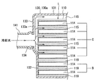
本発明の第3実施形態によるEGRガスクーラ200では、本発明の第1実施形態によるEGRガスクーラ100に対して、チューブおよびケーシングの形状を変更している。すなわち、図14に示すように、チューブとして単純な扁平パイプ状の第1第1チューブ210および第2チューブ270を用いると共に、ケーシングとして略筒状のケーシング230を用いている。以下に、本発明の第3実施形態によるEGRガスクーラ200の構成について簡単に説明する。
(Third embodiment)
In the EGR gas cooler 200 according to the third embodiment of the present invention, the shapes of the tube and the casing are changed with respect to the EGR gas cooler 100 according to the first embodiment of the present invention. That is, as shown in FIG. 14, a simple flat pipe-shaped first
本発明の第3実施形態によるEGRガスクーラ200を構成する各部材は、エンジンの排気ガスおよび冷却水に直接触れため、本発明の第1実施形態によるEGRガスクーラ100と同様に、耐腐食性および高温強度に優れるステンレス鋼材料から形成されるとともに、ろう付け、あるいは溶接により接合されている。 Since each member constituting the EGR gas cooler 200 according to the third embodiment of the present invention directly touches the exhaust gas and cooling water of the engine, the corrosion resistance and high temperature are similar to those of the EGR gas cooler 100 according to the first embodiment of the present invention. It is formed from a stainless steel material having excellent strength, and is joined by brazing or welding.
第1チューブ210は、図14に示すように、内部にインナーフィン220が配設されている。複数の第1チューブ210が、その延設方向(図14中において矢印で示す方向X)と直交する方向(図14中において矢印で示す方向Y)に隙間Dを保ちつつ積層され、且つその両端部をコアプレート260に接合されて、図15に示すように、第1チューブ群Aを形成している。各第1チューブ210は、コアプレート260に第1チューブ210と嵌合可能に設けられた孔部261に嵌合してコアプレート260に接合固定されている。第1チューブ群Aの積層方向において最外側に配置される第1チューブ210Aの外側(図15においては下側)には、図15示すように、第2チューブ270が配置されている。第1チューブ210は、その内部を排気ガス通過中に冷却水と熱交換を行う冷却通路Cを形成している。一方、第2チューブ270は、その内部を排気ガス通過中に冷却水との熱交換が行われず、したがって排気ガスの温度低下を抑制可能なバイパス通路Bを形成している。
As shown in FIG. 14, the
両コアプレート260の外側(第1チューブ210および第2チューブ270と反対側)には、図14に示すように、接続フランジ251が接合固定されている。EGRガスクーラ200は、接続フランジ251を介して、エンジンの排気管と吸気管とを連通する図示しないEGR通路に接続されている。接続フランジ251は、図14に示すように、略四角形状に形成されるとともに、その四隅に、ボルト等を挿通させてEGRガスクーラ200を図示しないEGR通路に接続固定するための貫通孔である取付け孔251aを備えている。
As shown in FIG. 14, a
ケーシング230は、図14に示すように、それぞれコ字状に形成された2つのケーシング部材230A、230Bを、互いの開口端部を重ね合わせて接合し、それにより角筒状に形成されている。すなわち、ケーシング230は、両コアプレート260間にケーシング部材230A、230Bの両端を当接させつつ第1チューブ210および第2チューブ270を覆うように挿入された後、互いの開口端部を重ね合わせて接合されている。なお、ケーシング部材230Aとケーシング部材230Bとの接合部は、本実施例のような重ね合わせ方式に限るものではなく、互いの開口端部を突き当てる方式であってもよい。
As shown in FIG. 14, the
ケーシング230には、第1チューブ210の断面長手方向外側(図15中において左側)に張出す第1膨出部231と、内容積が第1膨出部231よりも大きい第2膨出部235が形成されている。すなわち、第1膨出部231は、ケーシング部材230Aに形成され、第1膨出部231には、図15に示すように、パイプ孔234が設けられ、このパイプ孔234に、流入管である入口水パイプ241が嵌合し接合されている。同様に、第2膨出部235は、ケーシング部材230Bに形成され、第2膨出部235にもパイプ孔234が設けられ、このパイプ孔234に、流出管である出口水パイプ242が嵌合し接合されている。入口水パイプ241および出口水パイプ242は、図示しないエンジン冷却水回路に接続されている。ケーシング230に形成された両膨出部231、235は、図15に示すように、第2流体通路である冷却水流路215に連通している。
The
ケーシング230は、区画壁面としての平面部232を備えている。平面部232は、図15に示すように、第2チューブ270に隣接する第1チューブである第1チューブ210Aの端面に密着接合されている。第2チューブ270の周囲には、図15に示すように、断熱空間219が形成されている。このように、平面部232が第1チューブ210Aに密着接合されることにより、ケーシング230内において、冷却水流路215と、断熱空間219とが完全に隔離されている。すなわち、断熱空間219内には冷却水は流入せずに空気が封入されている。このため、排気ガスが第2チューブ270内を通過中に排気ガスから第2チューブ270を介して外部へ放散される熱量は抑制される。
The
本発明の第3実施形態によるEGRガスクーラ200では、ケーシング230の平面部232は、図15に示すように、第2チューブ270の端面にも密着固定されている。しかし、必ず平面部232を第2チューブ270の端面に密着固定する必要はなく、離れていてもよい。
In the EGR gas cooler 200 according to the third embodiment of the present invention, the
本発明の第3実施形態によるEGRガスクーラ200において、排気ガスは、図14において左端側から第1チューブ210のガス通路214に流入し、図14において右端側から流出する。一方、冷却水は、入口水パイプ241から容積室231を経て冷却水流路215へ流入し、冷却水流路215の対角線上反対側の容積室235へ至り、出口水パイプ242からEGRガスクーラ200外へ流出する。上述したように、EGRガスクーラ200内を排気ガスおよび冷却水が通過することにより、冷却通路Cを構成する第1チューブ210においては、ガス通路214を流れる排気ガスと第1チューブ210外を流れる冷却水との間で熱交換が行われ、排気ガスが冷却される。一方、バイパス通路Bを構成する第2チューブ270は、図15に示すように、空気が封入された断熱空間219に囲まれているため、ガス通路214を流れる排気ガスの温度低下を抑制することが可能である。
In the EGR gas cooler 200 according to the third embodiment of the present invention, the exhaust gas flows into the
本発明の本発明の第3実施形態によるEGRガスクーラ100においては、ケーシング230の平面部232を、第2チューブ270に隣接する第1チューブである第1チューブ210Aの端面に密着接合している。これにより、ケーシング230内において第1チューブ210の周囲に形成された冷却水流路215と、第2チューブ270の周囲に形成された断熱空間219とを隔離することができる。すなわち、従来の排気熱交換器において冷却通路とバイパス通路とを隔離している仕切り板を用いることなく、冷却通路Cとバイパス通路Bとを隔離することができる。以上から、一体的に備えた冷却通路Cとバイパス通路Bとを従来の仕切り板を用いない容易な手段によって隔離可能なEGRガスクーラ200を提供することができる。
In the EGR gas cooler 100 according to the third embodiment of the present invention, the
なお、以上説明した、本発明の第1、第2実施形態に対して、チューブ基本面111に形成される凹部113の形状は種々変更して対応することができる。即ち、凹部113のへこみ寸法は凸部112の突出寸法と同一となるようにしたが、この凹部113によって形成される流入部113a、流出部113bにおける冷却水の流通抵抗に応じて、凸部112の突出部寸法より小さくなるようにしても良い。あるいは、凸部112の突出寸法より大きくなるようにしても良い。
In addition, the shape of the recessed
また、2つの凹部113の設定位置は、チューブ基本面111の対角の位置に限らず、2個ともチューブ基本面111の一方の長辺側に設けるようにしても良い。この場合、入口水パイプ141、出口水パイプ142を同一のチューブ側面118側に設定でき、これに伴ってケーシング130は、第1、第2ケーシング130a、130bの2つに分割することなく、1つのタンクとして形成することができる。
Further, the setting positions of the two
また、チューブ基本面111における整流張出し部117は、チューブ基本面111の短辺に対して平行に延びる張出し部として形成したが、冷却水流路115における冷却水の流通状況に応じて、下流側に向けて短辺側との距離が拡がるものとしたり、曲線を描いて延設されるもの等としても良く、更には、整流張出し部117を廃止したものとしても良い。
In addition, the rectifying overhanging
また、ケーシング130(第1、第2ケーシング130a、130b)の外方部131は、排気ガスに対する熱交換性能に応じて、廃止しても良い。
Further, the
また、上記第1〜第3実施形態では本発明の熱交換器をEGRガスクーラ100に適用したものとして説明したが、これに限定されることなく、他の熱交換器へも広く適用可能であり、例えば外気に排出される排気ガスと冷却水との間で熱交換して、冷却水を加熱する排熱回収熱交換器に適用しても良い。
Moreover, although the said 1st-3rd embodiment demonstrated as what applied the heat exchanger of this invention to the
また、上記第1〜第3実施形態では熱交換器を構成する部材の基本材質をステンレス系材料としたが、これに限らず、用途に応じて、アルミニウム系合金、銅系合金等他の材料を用いるものにも適用できる。 Moreover, in the said 1st-3rd embodiment, although the basic material of the member which comprises a heat exchanger was made into the stainless steel material, according to a use, other materials, such as an aluminum alloy and a copper alloy, It is applicable also to what uses.
100 EGRガスクーラ(熱交換器、排気熱交換器)
110 チューブ
110a、110b チューブプレート
111 チューブ基本面(対向面)
111a 最外面
111b 突起部
112 凸部
113 凹部(流入部、流出部)
114 ガス通路
115 冷却水流路(流路)
117 整流張出し部(整流手段)
119 断熱空間
120 インナーフィン
121 隔壁板(空間維持部材)
130 ケーシング
131 外方部(外方板部材)
132 接続部(接続板部材)
133 膨出部
134 パイプ穴(開口部)
151 接続フランジ
160 隔壁板(板部材)
161a 延出部
200 EGRガスクーラ(熱交換器、排気熱交換器)
210 第1チューブ
210A 第1チューブ
211 隙間
212 流路
214 ガス通路
215 冷却水流路(第2流体通路)
219 断熱空間
220 インナーフィン
230 ケーシング
230A、230B ケーシング部材
231 第1膨出部
232 平面部(区画壁面)
234 パイプ孔
235 第2膨出部
241 入口水パイプ(流入管)
242 出口水パイプ(流出管)
251 接続フランジ
260 コアプレート
261 孔部
270 第2チューブ
A 第1チューブ群
B バイパス通路
C 冷却通路
D 隙間
L 積層体
100 EGR gas cooler (heat exchanger, exhaust heat exchanger)
110
111a
114
117 Rectification overhang (rectification means)
119
130
132 Connection part (connection plate member)
133
151 Connection flange 160 Bulkhead plate (plate member)
210
219
234
242 Outlet water pipe (outflow pipe)
251
Claims (15)
積層方向において最外側に配される前記第1チューブ(210)の外側に積層配置され、内部を第1流体が通過する第2チューブ(270)と、
前記第1チューブ群(A)と前記第2チューブ(270)とを内部に納めたケーシング(230)と、
前記ケーシング(230)の内部に形成され、前記第1チューブ群(A)が配され、前記第1チューブ群(A)を通過する前記第1流体と熱交換する第2流体が通過する第2流体通路(215)と、
前記ケーシング(230)の内部に前記第2チューブ(270)が配され、前記第2チューブ(270)の周囲に断熱空間(219)を形成するバイパス通路(B)と、
前記チューブの端部と連通し、前記複数のチューブへと前記第1流体を分配する、または前記複数のチューブを通過した前記第1流体を集める接続フランジ(251)と、
前記チューブの端部が挿通され、前記ケーシング(230)の内部と前記接続フランジ(251)とを区画するコアプレート(260)とを有する熱交換器であって、
前記ケーシング(230)は、
前記第1のチューブ(210)の断面長手方向よりも膨出し、前記第2流体通路(215)の一部をなす第1膨出部(231)と、
積層方向において前記第2チューブ(270)に隣接して配される前記第1チューブ(210)の断面長手方向の端面と当接することにより、前記第2流体通路(215)と前記断熱空間(219)とを区画する区画壁面(232)と、を有することを特徴とする熱交換器。 A first tube group (A) composed of a plurality of flat first tubes (210) arranged in a stack and through which the first fluid passes;
A second tube (270) disposed on the outer side of the first tube (210) disposed on the outermost side in the stacking direction, and through which the first fluid passes;
A casing (230) in which the first tube group (A) and the second tube (270) are housed;
A second fluid is formed inside the casing (230), the first tube group (A) is disposed, and a second fluid that exchanges heat with the first fluid that passes through the first tube group (A) passes therethrough. A fluid passageway (215);
A bypass passage (B) in which the second tube (270) is arranged inside the casing (230) and forms a heat insulation space (219) around the second tube (270);
A connection flange (251) that communicates with an end of the tube, distributes the first fluid to the plurality of tubes, or collects the first fluid that has passed through the plurality of tubes;
A heat exchanger having a core plate (260) through which an end of the tube is inserted and defining the inside of the casing (230) and the connection flange (251);
The casing (230)
A first bulge portion (231) that bulges from the cross-sectional longitudinal direction of the first tube (210) and forms part of the second fluid passage (215);
The second fluid passage (215) and the heat insulating space (219) are brought into contact with the end surface of the first tube (210) disposed adjacent to the second tube (270) in the stacking direction in the longitudinal direction of the cross section. ) and the heat exchanger and having a, a partition wall (232) partitioning the.
前記ケーシング(230)に接続され、前記第2流体を前記第2流体通路(215)から流出させる流出管(242)とを有し、
前記第1膨出部(231)は前記流入管及び前記流出管(242)の接続部位に形成されていることを特徴とする請求項1記載の熱交換器。 An inflow pipe (241) connected to the casing (230) for allowing the second fluid to flow into the second fluid passage (215);
An outlet pipe (242) connected to the casing (230) and allowing the second fluid to flow out of the second fluid passage (215);
The heat exchanger according to claim 1, wherein the first bulging portion (231) is formed at a connection portion of the inflow pipe and the outflow pipe (242).
前記流出管が前記ケーシング(230)に接続される接続部位には前記第1膨出部(231)よりも内容積が大きい第2膨出部(235)が形成されていることを特徴とする請求項1または2記載の熱交換器。 An outlet pipe (242) connected to the casing (230) for allowing the second fluid to flow out of the second fluid passage (215);
A connecting portion where the outflow pipe is connected to the casing (230) is formed with a second bulging portion (235) having a larger internal volume than the first bulging portion (231). The heat exchanger according to claim 1 or 2.
前記チューブ(110)が積層される際に互いに対向する対向面(111)の外周に形成されて外方へ突出する凸部(112)と、
前記凸部(112)の前記対向面(111)の長辺側の2ヶ所以上に形成され且つ前記凸部(112)に対して凹状となる凹部(113)とを備え、
複数の前記チューブ(110)は前記凸部(112)を互いに当接させて積層され、
隣接する2つの前記チューブ(110)間において前記対向面(111)および前記凸部(112)に囲まれる空間が前記第2流体の流通する流路(115)となり、
前記チューブ(110)の前記凹部(113)が形成される側の側面(118)に当接し且つ前記凹部(113)を包含するように接続板部材(132)が設けられ、
前記接続板部材(132)は外側に張出すように形成された容積室(133)を備え、
前記接続板部材(132)は、複数の前記チューブ(110)の積層方向における一端側に形成された前記凹部(113)を塞ぎ且つ残りの前記凹部(113)を前記容積室(133)に連通させて前記側面(118)に固定され、
前記接続板部材(132)により塞がれた前記凹部(113)に連通する前記流路(115)は密閉され且つ空気が封入された断熱空間(119)を形成し、
前記容積室(133)は外部の第2流体回路に接続されるジョイント部(141、142)を備え、
前記ジョイント部(141、142)および前記容積室(133)を介して前記流路(115)内へ前記第2流体の流入、あるいは前記隙間内から前記第2流体が流出することを特徴とする熱交換器。 A heat exchanger that exchanges heat between a first fluid that flows through a tube (110) that has a flat cross-section and is stacked, and a second fluid that flows outside the tube (110),
A convex portion (112) formed on the outer periphery of the opposing surface (111) facing each other when the tube (110) is laminated, and projecting outward;
A concave portion (113) that is formed at two or more locations on the long side of the opposing surface (111) of the convex portion (112) and is concave with respect to the convex portion (112),
The plurality of tubes (110) are stacked with the convex portions (112) in contact with each other,
A space surrounded by the facing surface (111) and the convex portion (112) between two adjacent tubes (110) becomes a flow path (115) through which the second fluid flows,
A connecting plate member (132) is provided so as to contact the side surface (118) of the tube (110) where the concave portion (113) is formed and to include the concave portion (113),
The connection plate member (132) includes a volume chamber (133) formed so as to project outward,
The connecting plate member (132) closes the concave portion (113) formed on one end side in the stacking direction of the plurality of tubes (110) and communicates the remaining concave portion (113) with the volume chamber (133). Fixed to the side surface (118),
The flow path (115) communicating with the recess (113) blocked by the connection plate member (132) forms a heat insulation space (119) that is sealed and enclosed with air,
The volume chamber (133) includes joint portions (141, 142) connected to an external second fluid circuit,
The second fluid flows into the flow path (115) through the joint portions (141, 142) and the volume chamber (133), or the second fluid flows out of the gap. Heat exchanger.
2つの前記最外面(111a)の少なくとも一方の更に外方から前記凸部(112)に当接する外方板部材(131)が設けられたことを特徴とする請求項5に記載の熱交換器。 The convex portion (112) and the concave portion (113) are formed on at least one of the two outermost surfaces (111a) which are both outermost in the stacking direction of the tube (110),
The heat exchanger according to claim 5, further comprising an outer plate member (131) that abuts against the convex portion (112) from the outer side of at least one of the two outermost surfaces (111a). .
2つの前記外方板部材(131)は、前記対向面(111)の一方の長辺側で前記接続板部材(132)と接続されたことを特徴とする請求項6に記載の熱交換器。 The outer plate member (131) is provided on the two outermost surfaces (111a),
The heat exchanger according to claim 6, wherein the two outer plate members (131) are connected to the connection plate member (132) on one long side of the facing surface (111). .
外側に膨出するように容積室(133)が形成され、積層された前記複数本のチューブ(110)の外周に配されるケーシング(130)と、 A volume chamber (133) formed so as to bulge outward, and a casing (130) disposed on the outer periphery of the plurality of tubes (110) stacked,
前記容積室(133)に接続され、前記ケーシング内部に第2流体を流出入させるジョイント部(141、142)と、を有する熱交換器において、 A heat exchanger connected to the volume chamber (133) and having joint portions (141, 142) for allowing the second fluid to flow into and out of the casing;
前記チューブ(110)は、 The tube (110)
積層される際に互いに対向する対向面(111)の外周に形成されて外方へ突出する凸部(112)と、前記対向面(111)の長辺側に形成され且つ前記凸部(112)に対して凹状となる凹部(113)とを備え、 A convex part (112) formed on the outer circumference of the opposing surface (111) facing each other when stacked, and a convex part (112) protruding outward, and formed on the long side of the opposing surface (111) and the convex part (112 ) And a recess (113) that is concave with respect to
複数の前記チューブ(110)は前記凸部(112)を互いに当接させて積層されており、 The plurality of tubes (110) are stacked such that the convex portions (112) are in contact with each other,
前記ケーシング(130)が、前記チューブ(110)の前記凹部(113)が形成される側の側面に当接され、 The casing (130) is brought into contact with a side surface of the tube (110) on which the concave portion (113) is formed;
前記複数のチューブ(110)のうち、前記凹部(113)が前記容積室(133)に対向するように配される複数本のチューブ(110)によって冷却通路(C)が形成され、 Among the plurality of tubes (110), a cooling passage (C) is formed by a plurality of tubes (110) arranged so that the concave portion (113) faces the volume chamber (133),
前記冷却通路(C)を形成する複数本の前記チューブ(110)の前記凹部(113)と前記容積室(133)とが連通し、前記第2流体が流れる第2流体通路(115)が形成され、 The recesses (113) of the plurality of tubes (110) forming the cooling passage (C) communicate with the volume chamber (133) to form a second fluid passage (115) through which the second fluid flows. And
前記冷却通路(C)と隣接して配され、前記冷却通路(C)を形成するチューブ(110)を除いた残りの前記チューブ(110)によって形成されるバイパス通路(B)が形成され、 A bypass passage (B) formed by the remaining tube (110) excluding the tube (110) that is arranged adjacent to the cooling passage (C) and forms the cooling passage (C) is formed,
前記バイパス通路(B)の前記チューブ(110)の前記凹部(113)が前記ケーシング(130)によって塞がれ、前記バイパス通路(B)の前記チューブ(110)の周囲に断熱空間(119)が形成されることを特徴とする熱交換器。 The recess (113) of the tube (110) of the bypass passage (B) is closed by the casing (130), and a heat insulating space (119) is formed around the tube (110) of the bypass passage (B). A heat exchanger characterized by being formed.
Priority Applications (5)
| Application Number | Priority Date | Filing Date | Title |
|---|---|---|---|
| JP2007054631A JP4775287B2 (en) | 2006-10-18 | 2007-03-05 | Heat exchanger |
| DE102007049665A DE102007049665A1 (en) | 2006-10-18 | 2007-10-17 | Exhaust gas recirculation cooler, for use in e.g. diesel engine, has housing side wall with inner surface which stays in contact with side wall of pipe so that space is separated from connecting chamber and fluid channels |
| US11/975,151 US7984753B2 (en) | 2006-10-18 | 2007-10-17 | Heat exchanger |
| CN2011100209615A CN102062025B (en) | 2006-10-18 | 2007-10-18 | Heat exchanger |
| CN2007101671319A CN101165332B (en) | 2006-10-18 | 2007-10-18 | Heat exchanger |
Applications Claiming Priority (3)
| Application Number | Priority Date | Filing Date | Title |
|---|---|---|---|
| JP2006284190 | 2006-10-18 | ||
| JP2006284190 | 2006-10-18 | ||
| JP2007054631A JP4775287B2 (en) | 2006-10-18 | 2007-03-05 | Heat exchanger |
Publications (2)
| Publication Number | Publication Date |
|---|---|
| JP2008121658A JP2008121658A (en) | 2008-05-29 |
| JP4775287B2 true JP4775287B2 (en) | 2011-09-21 |
Family
ID=39277856
Family Applications (1)
| Application Number | Title | Priority Date | Filing Date |
|---|---|---|---|
| JP2007054631A Expired - Fee Related JP4775287B2 (en) | 2006-10-18 | 2007-03-05 | Heat exchanger |
Country Status (4)
| Country | Link |
|---|---|
| US (1) | US7984753B2 (en) |
| JP (1) | JP4775287B2 (en) |
| CN (2) | CN101165332B (en) |
| DE (1) | DE102007049665A1 (en) |
Families Citing this family (47)
| Publication number | Priority date | Publication date | Assignee | Title |
|---|---|---|---|---|
| CN101688763B (en) * | 2007-04-11 | 2014-08-20 | 贝洱两合公司 | Heat exchanger |
| JP5293077B2 (en) * | 2007-10-30 | 2013-09-18 | 株式会社デンソー | Heat exchanger |
| EP2315995B1 (en) * | 2008-04-17 | 2019-06-12 | Dana Canada Corporation | U-flow heat exchanger |
| FR2933176B1 (en) * | 2008-06-26 | 2017-12-15 | Valeo Systemes Thermiques Branche Thermique Moteur | HEAT EXCHANGER HAVING A HEAT EXCHANGE BEAM AND A HOUSING |
| JP2010048536A (en) * | 2008-08-25 | 2010-03-04 | Denso Corp | Heat exchanger |
| JP2010145014A (en) * | 2008-12-18 | 2010-07-01 | Denso Corp | Heat exchanger |
| IT1393773B1 (en) * | 2009-03-16 | 2012-05-08 | Offidani | AIR AIR HEAT SINK AND PROCEDURE FOR ITS REALIZATION |
| US20100243228A1 (en) * | 2009-03-31 | 2010-09-30 | Price Richard J | Method and Apparatus to Effect Heat Transfer |
| BRPI1013063B1 (en) | 2009-05-18 | 2020-11-17 | Huawei Technologies Co., Ltd. | thermosyphon heat propagation device and method for making a thermosiphon heat propagation device |
| JP2011127819A (en) * | 2009-12-17 | 2011-06-30 | Mahle Filter Systems Japan Corp | Heat exchanger |
| JP5244845B2 (en) * | 2010-03-31 | 2013-07-24 | 株式会社ユタカ技研 | Heat exchanger |
| JP5533715B2 (en) * | 2010-04-09 | 2014-06-25 | 株式会社デンソー | Exhaust heat exchanger |
| EP2515064B1 (en) * | 2011-04-20 | 2014-06-04 | Senior Uk Limited | Heat exchanger |
| FR2977307B1 (en) * | 2011-06-30 | 2013-08-09 | Valeo Systemes Thermiques | STACKED PLATE EXCHANGER HOUSING AND EXCHANGER COMPRISING SUCH A HOUSING |
| JP5904108B2 (en) * | 2011-12-19 | 2016-04-13 | 株式会社デンソー | Exhaust heat exchanger |
| ES2409534B1 (en) * | 2011-12-22 | 2014-09-02 | Valeo Térmico, S. A. | HEAT EXCHANGER FOR GASES, ESPECIALLY OF EXHAUST GASES OF AN ENGINE |
| JP5903911B2 (en) * | 2012-02-02 | 2016-04-13 | トヨタ自動車株式会社 | Heat exchanger |
| DE102012211857A1 (en) * | 2012-07-06 | 2014-01-09 | Behr Gmbh & Co. Kg | Heat exchanger |
| DE102012106782A1 (en) | 2012-07-26 | 2014-01-30 | Halla Visteon Climate Control Corporation | Heat exchanger for exhaust gas cooling in motor vehicles |
| CN102900570B (en) * | 2012-09-20 | 2014-11-12 | 浙江银轮机械股份有限公司 | U-shaped exhaust gas recirculation (EGR) cooler |
| TWI468535B (en) * | 2012-11-20 | 2015-01-11 | Truan Sheng Lui | Method for inhibiting the diffusion of silicon by means of coarse aluminum crystals |
| US9109547B2 (en) * | 2013-04-25 | 2015-08-18 | GM Global Technology Operations LLC | Exhaust gas recirculation cooler, system, and method thereof |
| CN105518855B (en) * | 2013-08-30 | 2018-07-06 | 株式会社电装 | Laminated type cooler |
| JP6341530B2 (en) * | 2013-11-01 | 2018-06-13 | 臼井国際産業株式会社 | Multi-tube heat exchanger |
| DE102014201956A1 (en) * | 2014-02-04 | 2015-08-06 | MAHLE Behr GmbH & Co. KG | Pipe arrangement for a charge air cooler |
| JP6501472B2 (en) * | 2014-09-17 | 2019-04-17 | フタバ産業株式会社 | Exhaust heat recovery system |
| KR102142662B1 (en) * | 2014-10-17 | 2020-08-07 | 현대자동차주식회사 | Egr cooler for vehicle |
| JP6428252B2 (en) * | 2014-12-23 | 2018-11-28 | 株式会社デンソー | Power converter |
| DE102016001391A1 (en) * | 2015-02-23 | 2016-08-25 | Modine Manufacturing Company | HEAT EXCHANGER FOR COOLING ELOZE FLOATING OF DAMAGED AIR USING ANY FLUID COOLANT |
| US20170067416A1 (en) * | 2015-09-04 | 2017-03-09 | Sambo Motors | Manufacturing method for a housing of an exhaust gas recirculation cooler and housing panel structure therefor |
| EP3141861A1 (en) * | 2015-09-09 | 2017-03-15 | Sambo Motors | Method for manufacturing housing of exhaust gas recirculation cooler and housing panel therefor |
| CN107614860B (en) * | 2015-09-25 | 2020-03-03 | 翰昂汽车零部件有限公司 | EGR cooler for vehicle |
| DE102016200284B4 (en) * | 2016-01-13 | 2019-06-13 | Ford Global Technologies, Llc | Exhaust gas temperature regulation in a bypass duct of an exhaust gas recirculation system |
| EP3270085B1 (en) * | 2016-07-12 | 2019-11-06 | Borgwarner Emissions Systems Spain, S.L.U. | Heat exchanger for an egr system |
| DE102017208324A1 (en) * | 2017-05-17 | 2018-11-22 | Mahle International Gmbh | Heat exchanger |
| US10158104B1 (en) * | 2017-07-21 | 2018-12-18 | Swift Engineering, Inc. | Power cell casing |
| KR20190012628A (en) * | 2017-07-28 | 2019-02-11 | 현대자동차주식회사 | Aluminum plate and cooler having this |
| DE102017219433B4 (en) * | 2017-10-30 | 2022-08-11 | Hanon Systems | Heat exchanger for an internal combustion engine |
| EP3489604B1 (en) * | 2017-11-24 | 2020-12-23 | TitanX Holding AB | Vehicle condenser |
| ES2733747B2 (en) * | 2018-05-31 | 2021-10-07 | Valeo Termico Sa | HEAT EXCHANGER FOR GASES, ESPECIALLY FOR EXHAUST GASES FROM AN ENGINE |
| EP3587991A1 (en) * | 2018-06-28 | 2020-01-01 | Valeo Termico S.A. | Exhaust gas recirculation (egr) cooler |
| KR20200006779A (en) * | 2018-07-11 | 2020-01-21 | 현대자동차주식회사 | Exhaust gas recirculation cooler |
| US11255534B2 (en) * | 2018-10-03 | 2022-02-22 | Coretronic Corporation | Thermal module and projector |
| JP7159806B2 (en) * | 2018-11-21 | 2022-10-25 | トヨタ自動車株式会社 | Heat exchanger |
| CN111559218B (en) * | 2019-02-14 | 2022-10-14 | 浙江三花汽车零部件有限公司 | Heat exchanger |
| CN111561795A (en) * | 2019-02-14 | 2020-08-21 | 浙江三花汽车零部件有限公司 | Heat exchanger |
| CN109737782A (en) * | 2019-03-11 | 2019-05-10 | 北京丰联奥睿科技有限公司 | A kind of shell plate type heat exchanger |
Family Cites Families (24)
| Publication number | Priority date | Publication date | Assignee | Title |
|---|---|---|---|---|
| FR2575279B1 (en) * | 1984-12-21 | 1989-07-07 | Barriquand | PLATE HEAT EXCHANGER |
| US5893408A (en) * | 1995-08-04 | 1999-04-13 | Nautica Dehumidifiers, Inc. | Regenerative heat exchanger for dehumidification and air conditioning with variable airflow |
| JP4130512B2 (en) * | 1998-04-24 | 2008-08-06 | ベール ゲゼルシャフト ミット ベシュレンクテル ハフツング ウント コンパニー | Heat exchanger |
| DE19833338A1 (en) * | 1998-07-24 | 2000-01-27 | Modine Mfg Co | Heat exchangers, in particular exhaust gas heat exchangers |
| DE19841927A1 (en) | 1998-09-14 | 2000-03-16 | Wahler Gmbh & Co Gustav | Device for returning an exhaust gas flow to the intake manifold of an internal combustion engine |
| DE19962863B4 (en) | 1999-12-24 | 2013-09-19 | Behr Gmbh & Co. Kg | Heat exchanger |
| EP1343963B1 (en) | 2000-12-19 | 2008-04-09 | Valeo Termico S.A. | Heat-exchanger module, specially designed for an exhaust gas recycling system |
| US6516874B2 (en) * | 2001-06-29 | 2003-02-11 | Delaware Capital Formation, Inc. | All welded plate heat exchanger |
| DE10233407B4 (en) | 2001-07-26 | 2016-02-18 | Denso Corporation | Exhaust gas heat exchanger |
| DE10142539A1 (en) | 2001-08-30 | 2003-03-20 | Behr Gmbh & Co | Exhaust gas heat exchanger |
| DE10203003B4 (en) | 2002-01-26 | 2007-03-15 | Behr Gmbh & Co. Kg | Exhaust gas heat exchanger |
| DE10214467A1 (en) * | 2002-03-30 | 2003-10-09 | Modine Mfg Co | Exhaust gas heat exchanger for motor vehicles |
| DE10218521A1 (en) | 2002-04-25 | 2003-11-06 | Behr Gmbh & Co | Exhaust gas heat exchanger, especially for motor vehicles |
| CN100379971C (en) | 2002-05-15 | 2008-04-09 | 贝洱两合公司 | Controllable waste gas heat exchanger |
| ES2209618B1 (en) * | 2002-05-28 | 2005-08-16 | Estampaciones Noroeste, S.A. | HEAT EXCHANGER FOR AN "EGR" SYSTEM WITH AN INTEGRATED DERIVATION CONDUCT. |
| JP2004124808A (en) * | 2002-10-02 | 2004-04-22 | Hino Motors Ltd | Exhaust gas recirculation cooler |
| JP4140400B2 (en) | 2003-02-27 | 2008-08-27 | 株式会社デンソー | EGR cooling device |
| DE10312788A1 (en) * | 2003-03-21 | 2004-09-30 | Behr Gmbh & Co. Kg | Exhaust gas heat exchanger and sealing device for exhaust gas heat exchanger |
| JP2005036765A (en) * | 2003-07-18 | 2005-02-10 | Hino Motors Ltd | Egr cooler |
| WO2006035986A1 (en) * | 2004-09-28 | 2006-04-06 | T.Rad Co., Ltd. | Egr cooler |
| EP1801532B1 (en) * | 2004-09-28 | 2013-03-06 | T.RAD Co., Ltd. | Heat exchanger |
| US7195060B2 (en) * | 2005-04-01 | 2007-03-27 | Dana Canada Corporation | Stacked-tube heat exchanger |
| JP5145718B2 (en) | 2006-02-03 | 2013-02-20 | 株式会社デンソー | Heat exchanger |
| US7610949B2 (en) * | 2006-11-13 | 2009-11-03 | Dana Canada Corporation | Heat exchanger with bypass |
-
2007
- 2007-03-05 JP JP2007054631A patent/JP4775287B2/en not_active Expired - Fee Related
- 2007-10-17 US US11/975,151 patent/US7984753B2/en not_active Expired - Fee Related
- 2007-10-17 DE DE102007049665A patent/DE102007049665A1/en not_active Withdrawn
- 2007-10-18 CN CN2007101671319A patent/CN101165332B/en not_active Expired - Fee Related
- 2007-10-18 CN CN2011100209615A patent/CN102062025B/en not_active Expired - Fee Related
Also Published As
| Publication number | Publication date |
|---|---|
| DE102007049665A1 (en) | 2008-05-15 |
| CN102062025B (en) | 2012-12-26 |
| JP2008121658A (en) | 2008-05-29 |
| CN102062025A (en) | 2011-05-18 |
| US20080169093A1 (en) | 2008-07-17 |
| CN101165332B (en) | 2012-02-22 |
| US7984753B2 (en) | 2011-07-26 |
| CN101165332A (en) | 2008-04-23 |
Similar Documents
| Publication | Publication Date | Title |
|---|---|---|
| JP4775287B2 (en) | Heat exchanger | |
| JP5145718B2 (en) | Heat exchanger | |
| JP5293077B2 (en) | Heat exchanger | |
| EP2315995B1 (en) | U-flow heat exchanger | |
| JP5533715B2 (en) | Exhaust heat exchanger | |
| JP2015534030A (en) | Heat exchanger | |
| KR100925816B1 (en) | Exhaust gas heat exchanger | |
| US20170205153A1 (en) | Heat exchange device | |
| JP6276054B2 (en) | Heat exchanger | |
| EP2792988B1 (en) | Integrated heat exchanger for a vehicle | |
| WO2008072730A1 (en) | Compound heat exchanger and heat exchanger | |
| US7774937B2 (en) | Heat exchanger with divided coolant chamber | |
| KR101814027B1 (en) | Heat exchanger | |
| KR101775799B1 (en) | Exhaust gas heat exchanger with multiple heat exchanger channels | |
| JP4847162B2 (en) | Laminate heat exchanger | |
| JP2014214955A (en) | Heat exchanger | |
| JP2003106790A (en) | Exhaust heat exchanger | |
| US20130062039A1 (en) | System and method for exchanging heat | |
| JP2019211175A (en) | Multilayered heat exchanger and heat exchange unit with the multilayered heat exchanger | |
| CN116034246A (en) | Heat exchanger | |
| JP4284727B2 (en) | Heat exchanger | |
| JPH07103683A (en) | Heat exchanger | |
| KR20120071335A (en) | Stacked-plate heat exchanger | |
| JP7349821B2 (en) | Heat exchanger | |
| JP2024176321A (en) | Heat exchanger and compressor equipped with same |
Legal Events
| Date | Code | Title | Description |
|---|---|---|---|
| A621 | Written request for application examination |
Free format text: JAPANESE INTERMEDIATE CODE: A621 Effective date: 20090210 |
|
| A977 | Report on retrieval |
Free format text: JAPANESE INTERMEDIATE CODE: A971007 Effective date: 20101105 |
|
| A131 | Notification of reasons for refusal |
Free format text: JAPANESE INTERMEDIATE CODE: A131 Effective date: 20110125 |
|
| A521 | Request for written amendment filed |
Free format text: JAPANESE INTERMEDIATE CODE: A523 Effective date: 20110328 |
|
| TRDD | Decision of grant or rejection written | ||
| A01 | Written decision to grant a patent or to grant a registration (utility model) |
Free format text: JAPANESE INTERMEDIATE CODE: A01 Effective date: 20110531 |
|
| A01 | Written decision to grant a patent or to grant a registration (utility model) |
Free format text: JAPANESE INTERMEDIATE CODE: A01 |
|
| A61 | First payment of annual fees (during grant procedure) |
Free format text: JAPANESE INTERMEDIATE CODE: A61 Effective date: 20110613 |
|
| FPAY | Renewal fee payment (event date is renewal date of database) |
Free format text: PAYMENT UNTIL: 20140708 Year of fee payment: 3 |
|
| R250 | Receipt of annual fees |
Free format text: JAPANESE INTERMEDIATE CODE: R250 |
|
| R250 | Receipt of annual fees |
Free format text: JAPANESE INTERMEDIATE CODE: R250 |
|
| R250 | Receipt of annual fees |
Free format text: JAPANESE INTERMEDIATE CODE: R250 |
|
| LAPS | Cancellation because of no payment of annual fees |