JP4772237B2 - Industrial belt - Google Patents
Industrial belt Download PDFInfo
- Publication number
- JP4772237B2 JP4772237B2 JP2001294029A JP2001294029A JP4772237B2 JP 4772237 B2 JP4772237 B2 JP 4772237B2 JP 2001294029 A JP2001294029 A JP 2001294029A JP 2001294029 A JP2001294029 A JP 2001294029A JP 4772237 B2 JP4772237 B2 JP 4772237B2
- Authority
- JP
- Japan
- Prior art keywords
- warp
- paper
- weft
- surface side
- woven fabric
- Prior art date
- Legal status (The legal status is an assumption and is not a legal conclusion. Google has not performed a legal analysis and makes no representation as to the accuracy of the status listed.)
- Expired - Fee Related
Links
- 239000002759 woven fabric Substances 0.000 claims description 106
- 238000005304 joining Methods 0.000 claims description 31
- 239000000463 material Substances 0.000 claims description 28
- 229920002994 synthetic fiber Polymers 0.000 claims description 25
- 239000012209 synthetic fiber Substances 0.000 claims description 25
- 230000003373 anti-fouling effect Effects 0.000 claims description 18
- 239000000123 paper Substances 0.000 description 264
- 239000010410 layer Substances 0.000 description 70
- 229920000728 polyester Polymers 0.000 description 26
- 230000002829 reductive effect Effects 0.000 description 22
- 239000000126 substance Substances 0.000 description 21
- 230000000052 comparative effect Effects 0.000 description 20
- 230000002441 reversible effect Effects 0.000 description 20
- 239000004734 Polyphenylene sulfide Substances 0.000 description 15
- 239000004744 fabric Substances 0.000 description 15
- 229920000069 polyphenylene sulfide Polymers 0.000 description 15
- 230000036961 partial effect Effects 0.000 description 14
- 230000000694 effects Effects 0.000 description 11
- 230000006866 deterioration Effects 0.000 description 10
- 230000035699 permeability Effects 0.000 description 9
- 230000009467 reduction Effects 0.000 description 9
- 230000007423 decrease Effects 0.000 description 8
- 238000000034 method Methods 0.000 description 8
- 238000012360 testing method Methods 0.000 description 8
- 238000009941 weaving Methods 0.000 description 8
- 208000018747 cerebellar ataxia with neuropathy and bilateral vestibular areflexia syndrome Diseases 0.000 description 6
- 238000005520 cutting process Methods 0.000 description 6
- 239000004696 Poly ether ether ketone Substances 0.000 description 5
- 230000002411 adverse Effects 0.000 description 5
- 230000015556 catabolic process Effects 0.000 description 5
- 238000006731 degradation reaction Methods 0.000 description 5
- 230000006872 improvement Effects 0.000 description 5
- 229920002530 polyetherether ketone Polymers 0.000 description 5
- 229920000139 polyethylene terephthalate Polymers 0.000 description 5
- 239000005020 polyethylene terephthalate Substances 0.000 description 5
- 230000014759 maintenance of location Effects 0.000 description 4
- -1 polyethylene terephthalate Polymers 0.000 description 4
- 238000012545 processing Methods 0.000 description 4
- 239000002994 raw material Substances 0.000 description 4
- 239000002356 single layer Substances 0.000 description 4
- 229920003002 synthetic resin Polymers 0.000 description 4
- 239000000057 synthetic resin Substances 0.000 description 4
- 238000005406 washing Methods 0.000 description 4
- 238000005299 abrasion Methods 0.000 description 3
- 238000009825 accumulation Methods 0.000 description 3
- 238000009530 blood pressure measurement Methods 0.000 description 3
- 238000004140 cleaning Methods 0.000 description 3
- 239000011248 coating agent Substances 0.000 description 3
- 238000000576 coating method Methods 0.000 description 3
- 238000012790 confirmation Methods 0.000 description 3
- 230000008021 deposition Effects 0.000 description 3
- 239000000428 dust Substances 0.000 description 3
- 229920001707 polybutylene terephthalate Polymers 0.000 description 3
- 229920001343 polytetrafluoroethylene Polymers 0.000 description 3
- 239000004810 polytetrafluoroethylene Substances 0.000 description 3
- YCKRFDGAMUMZLT-UHFFFAOYSA-N Fluorine atom Chemical compound [F] YCKRFDGAMUMZLT-UHFFFAOYSA-N 0.000 description 2
- 235000010724 Wisteria floribunda Nutrition 0.000 description 2
- 239000000654 additive Substances 0.000 description 2
- 230000033228 biological regulation Effects 0.000 description 2
- 238000005336 cracking Methods 0.000 description 2
- 238000001035 drying Methods 0.000 description 2
- 230000007613 environmental effect Effects 0.000 description 2
- 239000000835 fiber Substances 0.000 description 2
- 238000007730 finishing process Methods 0.000 description 2
- 229910052731 fluorine Inorganic materials 0.000 description 2
- 239000011737 fluorine Substances 0.000 description 2
- 238000009998 heat setting Methods 0.000 description 2
- 239000007788 liquid Substances 0.000 description 2
- 239000010893 paper waste Substances 0.000 description 2
- 229920003207 poly(ethylene-2,6-naphthalate) Polymers 0.000 description 2
- 239000011112 polyethylene naphthalate Substances 0.000 description 2
- 238000003825 pressing Methods 0.000 description 2
- 230000002265 prevention Effects 0.000 description 2
- 230000008569 process Effects 0.000 description 2
- 229920005989 resin Polymers 0.000 description 2
- 239000011347 resin Substances 0.000 description 2
- XLYOFNOQVPJJNP-UHFFFAOYSA-N water Substances O XLYOFNOQVPJJNP-UHFFFAOYSA-N 0.000 description 2
- 244000043261 Hevea brasiliensis Species 0.000 description 1
- 230000009471 action Effects 0.000 description 1
- 239000000853 adhesive Substances 0.000 description 1
- 230000001070 adhesive effect Effects 0.000 description 1
- 230000001680 brushing effect Effects 0.000 description 1
- 239000011111 cardboard Substances 0.000 description 1
- 239000000356 contaminant Substances 0.000 description 1
- 238000011109 contamination Methods 0.000 description 1
- 230000003247 decreasing effect Effects 0.000 description 1
- 230000003111 delayed effect Effects 0.000 description 1
- 210000005069 ears Anatomy 0.000 description 1
- 235000013305 food Nutrition 0.000 description 1
- 238000010438 heat treatment Methods 0.000 description 1
- 238000012423 maintenance Methods 0.000 description 1
- 238000005259 measurement Methods 0.000 description 1
- 230000000877 morphologic effect Effects 0.000 description 1
- 229920003052 natural elastomer Polymers 0.000 description 1
- 229920001194 natural rubber Polymers 0.000 description 1
- 239000004745 nonwoven fabric Substances 0.000 description 1
- 239000011087 paperboard Substances 0.000 description 1
- 239000002689 soil Substances 0.000 description 1
- 229920003051 synthetic elastomer Polymers 0.000 description 1
- 239000005061 synthetic rubber Substances 0.000 description 1
- 238000010998 test method Methods 0.000 description 1
- 239000004753 textile Substances 0.000 description 1
- 238000004804 winding Methods 0.000 description 1
Images


Landscapes
- Woven Fabrics (AREA)
- Paper (AREA)
- Belt Conveyors (AREA)
Description
【0001】
【発明の属する技術分野】
本発明は、製紙機械用ドライヤーカンバスや製紙機械用搬送ベルトおよび各種工業用の搬送ベルトなどに用いられる工業用ベルトの改良に関する。
【0002】
【従来の技術】
一般に工業用ベルトが各種工業製品や加工物の搬送に用いられているが、例えば、製紙機械すなわち抄紙機のドライパートやカレンダーパート、塗工工程などの仕上工程では、製紙機械用ドライヤーカンバスや製紙機械用搬送ベルトが用いられる。また、不織布熱接着工程などの繊維製品・加工物および食品製品・加工物などの乾燥工程や熱処理工程におけるネットコンベアや搬送ベルトが知られている。
【0003】
例えば、製紙機械においては、抄紙機のドライパートで紙料原料中に含まれる粘着性油分のガム質ピッチ、あるいは製紙用糊剤であるサイズ液、塗工液などが汚れとなってドライヤーカンバスの表面に付着する。この汚れが経時的に堆積すると、カンバスの目詰まりを引き起こし、通気性が著しく低下してその乾燥作用を発揮し得なくなることから、抄紙用ドライヤーカンバスにおける汚れは従来から大きな問題であった。
【0004】
そこで、汚れがカンバス表面に付着し難く、また、汚れが付着してもその汚れを落とし易いように、単層の平織組織に織成した目の粗い多孔性の抄紙用ドライヤーカンバスが、例えば実公昭58−55280号公報において提案されている。
【0005】
この抄紙用ドライヤーカンバスは、太さが直径寸法0.6mmφ〜1.2mmφの合成樹脂モノフィラメントをそれぞれ経糸および緯糸とし、経糸密度および緯糸密度をともに8〜15本/2.54cmの超オープンメッシュにして単層の平織組織に織成し、経糸および緯糸をともにその組織点で同程度に波形状に湾曲固定するように緊張下のヒートセット加工を施し、通気度を30,000cm3/cm2・min以上としたものである。
【0006】
この抄紙用ドライヤーカンバスは、単層の平織組織でその経糸密度および緯糸密度をともに8〜15本/2.54cmと極めて目を粗くしたことから、湿紙と接触する経糸と緯糸との交絡点(交錯点)が少なくなり、汚れ物質がカンバス表面に付着することが少なくなり、また、目が粗いので、たとえ汚れ物質が付着しても、洗浄やブラッシング等によって容易に取り除くことができて防汚性に優れたものである。
【0007】
ところで、近年では、環境保護および資源再利用の観点から、製紙原料に古紙が多量に使われ始めたのに伴い、古紙中に含まれる天然ゴムや合成ゴム等の粘着性物質がカンバス表面に多く付着するという現象が発生している。そのため、ドライヤーカンバスにおける防汚対策は、従来よりもさらに厳しいものが要求されつつあり、前述の実公昭58−55280号公報に開示されたドライヤーカンバスでは、その厳しい要求に対する充分な対応が困難であるというのが現状であった。
【0008】
そこで、本出願人は、前述した状況に基づいてドライヤーカンバスにおける汚れ物質の付着原因および防汚対策を検討し、粘着性物質等の汚れ物質によるカンバス表面の汚れは、汚れ物質が主に経糸と緯糸の交絡点(交錯点)から付着して、経時的に堆積した結果のものであることに注目し、防汚対策として、湿紙と接触するカンバス表面での経糸と緯糸の交絡点(交錯点)を減少させることが有効であること、ならびに、経糸と緯糸の密度を減少させずに強度および寸法安定性を維持しながら、経糸と緯糸の交絡点(交錯点)を減少させるには、経糸と緯糸の密度を変えずに緯糸の太さを異ならせ、太い緯糸と細い緯糸とを交互に配するのが、湿紙と接触する交絡点(交錯点)が減少でき、しかも、ドライヤーカンバスの強力および寸法安定性が良いことを見出して、特開平9−310291号公報に開示の抄紙用ドライヤーカンバスを提案している。
【0009】
この抄紙用ドライヤーカンバスは、断面形状が円形の合成樹脂モノフィラメントを経糸および緯糸として単層の平織組織に織成した抄紙用ドライヤーカンバスであって、前記緯糸に太さが異なるモノフィラメントを交互に配して織成したことを特徴とするものである。さらに、前記合成樹脂モノフィラメントの太さが直径寸法0.6mmφ〜1.2mmφの範囲を望ましい範囲とするものであり、また、望ましい合成樹脂モノフィラメントとして、ポリエステルモノフィラメントを開示している。
【0010】
この抄紙用ドライヤーカンバスは、カンバス表面で湿紙と接触する経糸と緯糸の交絡点(交錯点)を減少させることができるので、汚れ物質のドライヤーカンバスへの付着量を大幅に減少して、汚れ防止に顕著な効果が発揮できる上に、強力および寸法安定性が優れたドライヤーカンバスである。
【0011】
【発明が解決しようとする課題】
ところで、近年では、前述のとおり、環境保護や資源再利用の観点から、製紙原料としての古紙使用量がますます増加しており、特に、板紙やダンボール原紙等の重量物の抄紙では、古紙原料比100%といった操業もごく一般的になっている。その結果、前述の汚れ物質のカンバス織組織への付着・堆積への対策、あるいは、付着した汚れの洗浄性向上に関するユーザー要求が、例えば前述の実公昭58−55280号公報の出願当時と比べると、格段に厳しくなっている。
【0012】
上記、古紙原料比が極めて高い抄紙では、他の抄紙の場合に比べて、原料中の微細繊維による紙紛汚れが多く有り、また内添剤や塗工剤の使用量も多く、填料、夾雑物等も多く含まれるため、それら汚れ物質がドライヤーカンバスの表面や経糸と緯糸の交錯点の付近に付着、堆積する量も多量で、また、それら汚れ物質が紙シートとカンバスとの間に介在するため、ドライヤーカンバスの表面、特に接紙面側表面の摩耗の要因にもなる。
【0013】
また、抄紙機のカレンダーパートや、塗工工程などの仕上工程においても、紙紛、ホワイトピッチ等の内添剤および塗工剤などの汚れ物質が、シートとカンバスや搬送ベルトとの間に介在する状況で紙シートとの間の摩擦が生じると共に、ドクターブレード等との接触による摩耗も重畳するため、カンバスや搬送ベルトの表面、特に接紙面側表面の摩耗が進行し易い。また、ガイドロール等の機械装置との間での接触による、反接紙面側(機械面側)での摩耗も発生する。
【0014】
一方、ドライヤーカンバスに付着、堆積した汚れ物質のオンマシンでの除去方法として、高圧水洗浄や薬品を用いた洗浄方法が一般に行われるが、カンバス表面の付着物を掻き落とすために、金属製のスパイラル線で編成したネットあるいはスクレーパーが設置されて用いられる場合もあり、そのような場合には、それらとの接触によりカンバス表面の摩耗がより一層進展するので、カンバス表面、特に接紙面側表面の耐摩耗性の向上、ならびに、摩耗損傷を受ける条件下での強力や形態保性の維持も、前記防汚性や洗浄性の向上と併せて必要になっている。
【0015】
通常、ドライヤーカンバスは、複数本のドライヤーシリンダーおよびローラー間に無端状に捲回されて抄紙機に装着されて運動するが、そのため、長さ方向の両端部を接続して無端状となすための継手をカンバスの両端部に有している。
【0016】
その継手としては、カンバスの両端部において、カンバス織物を構成する経糸の一部を延長し、折り返して接合用ループを形成の後、カンバス本体内に綴り込んで形成し、このループ列を互いに噛み合わせて成る共通孔に接合芯線を挿通してカンバスを無端状に接続する、いわゆるワープループシームが一般的である。
【0017】
また、他の継手としては、カンバスの両端部において、カンバス織物を構成する経糸の一部を延長し、折り返してループを形成し、このループにスパイラル線をそれぞれ噛み合わせ、この噛み合い部の共通孔に固定芯線を挿通した後、カンバス本体内に綴り込んでおき、さらに2つのスパイラル線を互いに噛み合わせて成るスパイラル線相互の共通孔に接合芯線を挿通してカンバスを無端状に接続する、いわゆるスパイラルシームが一般的である。
【0018】
そして、上記接合用ループを形成する経糸もしくはスパイラル線を噛み合わせるためのループを形成する経糸に、カンバスを駆動する牽引力や張力が集中的に掛かる上に、上記接合用ループおよびスパイラル線を噛み合わせるためのループは、カンバス織物を構成する経糸の一部、例えば1/2もしくは1/4の本数の経糸で形成されるのが通常であるため、それら経糸の摩耗損傷により強力低下が生じると、早期に継手部分の破断を引き起こして、カンバスの使用不能を生じる危険性が高い。さらに、ポリエステルなど素材の特性によっては、高温・高湿の条件下での熱劣化による強力低下も重畳して影響する。
【0019】
そのため、上記接合用ループを形成する経糸もしくはスパイラル線を噛み合わせるためのループを形成する経糸の摩耗対策や、熱劣化および摩耗損傷を受ける条件下での経糸強力の低下対策が、カンバスや搬送ベルトにおける長寿命化(使用期間の延長)のために特に重要となってきている。
【0020】
一方、太い線径や断面積大なるモノフィラメントを経糸に用いて、経糸の厚さ方向寸法および単糸強力を大きくし、経糸の強力低下に対する摩耗の影響度合いを少なくして、早期の破断事故の発生を防ぐ等の工夫も成されているが、その場合でも、上記接合用ループおよびスパイラル線を噛み合わせるためのループを形成する経糸の摩耗損傷ならびに熱劣化による強力低下を、それ以外の経糸よりも減少させる効果を呈するまでには至っていない。
【0021】
したがって、本発明は、各種工業製品や加工物の搬送に用いられる工業用ベルト、例えば、製紙機械用ドライヤーカンバスや製紙機械用搬送ベルトであって、従来のものよりも防汚性ならびに洗浄による汚れ除去性能に優れると同時に、織物表面、特には湿紙と接する接紙面側表面での経糸の摩耗対策を図ること、ならびに、高温・高湿の条件に重畳して摩耗損傷を受ける使用条件下での経糸の強力低下を防止することにより、従来のものより使用期間の長い製紙機械用ドライヤーカンバスや製紙機械用搬送ベルトおよび各種工業用の搬送ベルトなどの工業用ベルトを提供することを目的とする。
【0022】
【課題を解決するための手段】
上記課題を達成するための技術的手段として、本発明は、合成繊維モノフィラメントの経糸および緯糸を用いた織成布から成る工業用ベルトであって、緯糸の層が、接紙面側の緯糸の層および反接紙面側の緯糸の層を含む少なくとも2層の緯糸の層を有し、前記接紙面側の緯糸の層および前記反接紙面側の緯糸の層が何れも太さの異なる緯糸を交互に配して成り、経糸が、接紙面側の1本の細い緯糸および反接紙面側の1本の細い緯糸を内側に織り込んで接紙面側および反接紙面側に経糸ナックルを形成する第1の経糸と、接紙面側の1本の太い緯糸および反接紙面側の1本の太い緯糸を内側に織り込んで接紙面側および反接紙面側に経糸ナックルを形成する第2の経糸を有し、前記第1の経糸が接紙面側および反接紙面側に形成する経糸ナックルが、前記第2の経糸が接紙面側および反接紙面側に形成する経糸ナックルにより規定される接紙面側表面および反接紙面側表面よりも織成布の厚さ方向内側に位置し、さらに、前記第2の経糸に、前記第1の経糸よりも耐熱性および/または耐摩耗性の優れた素材から成る合成繊維モノフィラメントを用いることを特徴とする(請求項1)。
【0023】
参考例は、前記接紙面側の緯糸の層および反接紙面側の緯糸の層が、太さの異なる緯糸を交互に配して成り、前記第2の経糸が反接紙面側に形成する経糸ナックルが、反接紙面側表面よりも織成布の厚さ方向内側に位置することを特徴とする。
【0024】
本発明は、上記のように、前記接紙面側の緯糸の層および反接紙面側の緯糸の層が、太さの異なる緯糸を交互に配して成り、前記第1の経糸が反接紙面側に形成する経糸ナックルが、反接紙面側表面よりも織成布の厚さ方向内側に位置することを特徴とする(請求項1)。
【0025】
参考例は、前記反接紙面側の緯糸の層が太さの等しい緯糸で構成され、前記第1の経糸が反接紙面側に形成する経糸ナックルと、前記第2の経糸が反接紙面側に形成する経糸ナックルとが、反接紙面側表面と同一面になっていることを特徴とする。
【0026】
本発明は、また、前記接紙面側および反接紙面側の緯糸の層のうち、少なくとも接紙面側の緯糸の層における、前記少なくとも太い緯糸に、前記第1の経糸よりも耐熱性の優れた素材から成る合成繊維モノフィラメントを用いることを特徴とする(請求項2)。
【0027】
本発明は、また、前記接紙面側および反接紙面側の緯糸の層のうち、少なくとも接紙面側の緯糸の層における、前記少なくとも太い緯糸に、前記第1の経糸よりも耐熱性および防汚性の優れた素材から成る合成繊維モノフィラメントを用いることを特徴とする(請求項3)。
【0028】
本発明は、また、前記工業用ベルトが、織成布を構成する経糸の一部を延長し、折り返して接合用ループを形成の後、織成布本体の織組織内に綴り込んで、このループ列を互いに噛み合わせて成る共通孔に接合芯線を挿通して織成布を無端状に接続するための継手を、織成布の長さ方向両端部に有する工業用ベルトであって、前記折り返して接合用ループを形成の後、織成布本体の織組織内に綴り込む経糸を、前記第1の経糸の一部または全部を用いて形成することを特徴とする(請求項4)。
【0029】
本発明は、また、前記折り返して接合用ループを形成の後、織成布本体の織組織内に綴り込む経糸の部分が形成する経糸ナックルであって、接紙面側表面および反接紙面側表面に形成する経糸ナックルが、織成布の表面より厚さ方向内側に位置することを特徴とする。
【0030】
本発明は、また、前記工業用ベルトが、織成布を構成する経糸の一部を延長し、折り返してループを形成し、このループにスパイラル線をそれぞれ噛み合わせ、この噛み合い部の共通孔に固定芯線を挿通した後、織成布本体の織組織内に綴り込んでおき、さらに2つのスパイラル線を互いに噛み合わせて成るスパイラル線相互の共通孔に接合芯線を挿通して織成布を無端状に接続するための継手を、織成布の長さ方向両端部に有する工業用ベルトであって、前記スパイラル線をそれぞれ噛み合わせるためのループを形成する経糸を、前記第1の経糸の一部または全部を用いて形成することを特徴とする(請求項5)。
【0031】
本発明は、また、前記折り返して接合用ループを形成し、このループにスパイラル線をそれぞれ噛み合わせ、この噛み合い部の共通孔に固定芯線を挿通した後、織成布本体の織組織内に綴り込む経糸の部分が形成する経糸ナックルであって、接紙面側表面および反接紙面側表面に形成する経糸ナックルが、織成布の表面より厚さ方向内側に位置することを特徴とする。
【0032】
【発明の実施の形態】
本発明の「工業用ベルト」なる用語は、合成繊維モノフィラメントの経糸および緯糸を用いた織成布から成る製紙機械用ドライヤーカンバスや製紙機械用搬送ベルトおよび各種工業用の搬送ベルトなどを総称する広義のものである。
【0033】
本発明においては、経糸および緯糸に合成繊維モノフィラメントを用いるので、マルチフィラメントや紡績糸を用いる場合よりも、糸条表面や内部への汚れ物質の付着、進入を防ぐことができ、防汚性ならびに付着・堆積した汚れ物質の除去性能も向上する。
【0034】
前記「合成繊維モノフィラメント」とは、PET(ポリエチレンテレフタレート)やPBT(ポリブチレンテレフタレート)、PEN(ポリエチレンナフタレート)などのポリエステル、またはPPS(ポリフェニレンサルファイド)、PEEK(ポリエーテルエーテルケトン)などの耐熱性能良好な素材を主体とする合成繊維モノフィラメントを言う。また、例えばPTFE(ポリテトラフルオロエチレン)モノフィラメントやフッ素系樹脂を含有したモノフィラメント等、防汚素材を含有したモノフィラメントを含む。
【0035】
織組織は、緯糸の層が、接紙面側の緯糸の層および反接紙面側の緯糸の層を含む少なくとも2層の緯糸の層を有する織組織とする。接紙面側の緯糸の層および反接紙面側の緯糸の層から成る緯2重の織組織を基本とするが、例えば通気度の設定範囲をより低くするためや織物の剛性を高めるために、接紙面側の緯糸の層と反接紙面側の緯糸の層との間に、さらに1層の追加の緯糸層を有する緯2.5重織もしくは緯3重織の織組織を用いることもできる。紙粉や汚れ物質の付着防止や付着した汚れ除去の観点から、追加する緯糸の層にも、合成繊維モノフィラメントを用いるのを好適とする。
【0036】
また、接紙面側および反接紙面側において、経糸が1本の緯糸を内側に織り込んで経糸ナックルを形成し、経糸の浮きを形成しない織組織を用いて、経糸が緯糸と交錯する箇所(交錯点)での経糸と緯糸の接触度合いを強め、織組織の剛性、形態保持性および走行安定性を良化させるのを好適とする。
【0037】
(第1実施形態)
図1は、第1の実施形態(参考例)における一例に係る工業用送ベルト10の織組織を示した経糸方向の断面図である。
【0038】
本発明の第1の実施形態における一例である工業用ベルト10は、経糸11が第1の経糸12と第2の経糸13とを有し、緯糸の層が接紙面側31の緯糸の層33と、反接紙面側32の緯糸の層34とを有する。前記接紙面側31の緯糸の層33および反接紙面側の緯糸の層34のうち、少なくとも接紙面側31の緯糸の層33を、太さの異なる緯糸21,22、すなわち太い緯糸21と細い緯糸22を交互に配した緯糸の層として構成する。また、反接紙面側32の緯糸の層34は、太さの等しい緯糸23によって構成する。反接紙面側32の緯糸23の太さは、接紙面側31の緯糸21または22と同じ太さまたは異なる太さとすることができる。織組織の形態安定性や剛性の点からは、少なくとも細い緯糸22の太さ以上で、太い緯糸21の太さ以下の範囲の太さとするのが望ましい。
【0039】
前記第1の経糸12は、接紙面側31の1本の細い緯糸22を内側に織り込んで、接紙面側31に経糸ナックル14aを形成すると共に、反接紙面側32の1本の緯糸23を内側に織り込んで反接紙面側32に経糸ナックル16aを形成する。また、前記第2の経糸13は、接紙面側31の1本の太い緯糸21を内側に織り込んで接紙面側31に経糸ナックル15aを形成すると共に、反接紙面側32の1本の緯糸23を内側に織り込んで反接紙面側32に経糸ナックル17aを形成する。
【0040】
さらに、経糸11を用いた織製布として、第1の経糸12が接紙面側31に形成する経糸ナックル14a(図中Bで示す位置にある)が、第2の経糸13が接紙面側31に形成する経糸ナックル15a(図中Aで示す位置にある)により規定される接紙面側表面35よりもベルト10の厚さ方向内側に位置するように構成する織製布である。なお、図1では第1の実施形態の好ましい一例として、第1の緯糸12が反接紙面側31に形成する経糸ナックル16aおよび第2の経糸13が反接紙面側32に形成する経糸ナックル17aは、反接紙面側32の反接紙面側表面36(図中Cで示す位置にある)と同一面になっている例を示したが、この例に限定するものではなく、径糸ナックル16aまたは17aのいずれかが反接紙面側表面36と同一面となればよい。
【0041】
上記構成とすることにより、接紙面側表面35に表出する経糸ナックルが、前記第2の経糸13が形成する経糸ナックル15aだけとなり、表出する経糸ナックルの数が減少するので、汚れ物質が経糸と緯糸の交錯点付近に付着すること、および付着した汚れ物質が経時的に堆積するのを防止することが可能となり、防汚性を向上させることが出来る。
【0042】
また、第1の経糸12が接紙面側31に形成する経糸ナックル14aの接紙面側表面35における摩耗の発生が、接紙面側表面35より内側に位置する分だけ遅れるので、その分だけ第1の経糸12の摩耗による強力低下の度合いを減少させることが出来る。
【0043】
さらに、接紙面側31における影響がより大きい高温・高湿条件による経糸12,13の熱劣化の度合いも、第1の経糸12が接紙面側31に形成する経糸ナックル14aが接紙面側表面35より内側に位置するので、例えば製紙機械用ドライヤーカンバスの場合、湿紙やドライヤーシリンダーに直接接触しない分だけ少なくなるため、熱劣化による第1の経糸12の強力低下が抑制されることも期待出来る。特に、湿紙と接しないドライヤーカンバスの両耳部においては、ドライヤーシリンダーから直接に熱負荷を受けるため、この効果は大きい。
【0044】
したがって、例えば製紙機械用ドライヤーカンバスや製紙機械用搬送ベルトの場合、摩耗損傷し強力低下を起こした経糸表面の部分的なひび割れやささくれ、およびそれが元での汚れ物質の付着・堆積の増加に起因する接紙面側31での表面性の劣化や、それによる紙シートの製品品質への悪影響の危険性が回避されて、製品品質の維持が長期にわたり可能になると共に、部分的な経糸の割れ等に因る経糸方向の強力の低下および形態保持性や走行性能の悪化を防ぐことが可能となり、従来のものよりも使用期間の長い工業用ベルトを実現することが出来る。
【0045】
(第2実施形態)
次に、図2は、第2の実施形態(参考例)における一例に係る工業用ベルト50の織組織を示した経糸方向の断面図である。
【0046】
本発明の第2の実施形態における一例である工業用ベルト50は、前述の第1の実施形態における構成に加えて、接紙面側31の緯糸の層33および反接紙面側の緯糸の層34を、太さの異なる緯糸21,22および24,25、すなわち太い緯糸21と細い緯糸22、および太い緯糸24と細い緯糸25を、それぞれの層において交互に配した緯糸の層33および34としている。同時に、第1の経糸12が、接紙面側31の1本の細い緯糸22を内側に織り込んで接紙面側31に経糸ナックル14bを形成すると共に、反接紙面側32の1本の太い緯糸24を内側に織り込んで反接紙面側32に経糸ナックル16bを形成し、第2の経糸13が、接紙面側31の1本の太い緯糸21を内側に織り込んで接紙面側31に経糸ナックル15bを形成すると共に、反接紙面側32の1本の細い緯糸25を内側に織り込んで反接紙面側32に経糸ナックル17bを形成し、第2の経糸13が形成する経糸ナックル17b(図中Dで示す位置にある)が、第1の経糸12が形成する経糸ナックル16b(図中Cで示す位置にある)により規定される反接紙面側表面36よりも厚さ方向内側に位置する織製布である。
【0047】
(第3実施形態)
また、図3は、本発明の第3の実施形態における一例に係る工業用ベルト60の織組織を示した経糸方向の断面図である。
【0048】
本発明の第3の実施形態における一例である工業用ベルト60は、前述の第1の実施形態における構成に加えて、接紙面側31の緯糸の層33および反接紙面側32の緯糸の層34を、太さの異なる緯糸21,22および24,25、すなわち太い緯糸21と細い緯糸22および太い緯糸24と細い緯糸25を、それぞれの層において交互に配した緯糸の層33および34とすると同時に、第1の経糸12が、接紙面側31の1本の細い緯糸22を内側に織り込んで接紙面側31に経糸ナックル14cを形成すると共に、反接紙面側32の1本の細い緯糸25を内側に織り込んで反接紙面側32に経糸ナックル16cを形成し、第2の経糸13が、接紙面側31の1本の太い緯糸21を内側に織り込んで接紙面側31に経糸ナックル15cを形成すると共に、反接紙面側32の1本の太い緯糸24を内側に織り込んで反接紙面側32に経糸ナックル17cを形成し、第1の経糸12が形成する経糸ナックル16c(図中Fで示す位置にある)が、第2の経糸13が形成する経糸ナックル17c(図中Eで示す位置にある)により規定される反接紙面側表面36よりも厚さ方向内側に位置する織製布である。
【0049】
図2に示す第2の実施形態のベルト50においては、接紙面側31の緯糸の層33における太い緯糸21と、反接紙面側32の緯糸の層34における細い緯糸25とが、織成布の厚さ方向に重なり合い、かつ、接紙面側31の緯糸の層33における細い緯糸22と、反接紙面側32の緯糸の層34における太い緯糸24とが、織成布の厚さ方向に重なり合うように構成することができる。
【0050】
一方、図3に示す第3の実施形態のベルト60では、接紙面側31の緯糸の層33における太い緯糸21と、反接紙面側32の緯糸の層34における太い緯糸24とが、織成布の厚さ方向に重なり合い、かつ、接紙面側31の緯糸の層33における細い緯糸22と、反接紙面側32の緯糸の層34における細い緯糸25とが、織成布の厚さ方向に重なり合うように構成することができる。
【0051】
なお、上記図1、図2および図3において、( )内にアラビア数字で示した経糸配置順番は、その一例を示したもので、本発明の実施形態を特に限定するものではない。
【0052】
上記第2の実施形態および第3の実施形態の場合には、前述の第1の実施形態における場合の、接紙面側表面35へ表出する経糸ナックルの数の減少による接紙面側31での防汚性向上の効果に加えて、反接紙面側表面36へ表出する経糸ナックルの数の減少による反接紙面側32での防汚性向上の効果も得られるので、より好ましい。
【0053】
また、特に第3の実施形態の場合には、第1の経糸12が接紙面側31に形成する経糸ナックル14cの摩耗、ならびに、反接紙面側32に形成する経糸ナックル16cの摩耗を併せて抑制できて、第1の経糸12における強力低下の度合いが一層少なくなるので、より好ましい。
【0054】
本発明の実施においては、前述した構成にさらに加えて、前記第1の経糸12および前記第2の経糸13のうち、少なくとも一方の経糸に、他方の経糸よりも耐熱性および/または耐摩耗性の優れる素材から成る合成繊維モノフィラメントを用いるのが好ましい。
【0055】
例えば、接紙面側31における摩耗損傷や、高温・高湿の条件に重畳しての摩耗損傷を前記第1の経糸12よりも受けやすい前記第2の経糸13に、第1の経糸12に用いるモノフィラメントよりも耐熱性および/または耐摩耗性の優れる素材から成るモノフィラメントを用いれば、必ずしも第1の経糸12および第2の経糸13の両方に耐熱性および/または耐摩耗性の優れる素材から成るモノフィラメントを用いなくても、前述した構成によって第1の経糸12における強力低下の度合いを減少させ得ると同時に、第2の経糸13の耐熱性および/または耐摩耗性を強化できるので、低コストのもとに、工業用ベルトのより一層の使用期間の延長が図れ、好ましい。
【0056】
なお、例えば、第1の経糸12に、PETもしくはPBTなどのポリエステルモノフィラメントを用い、第2の経糸13に、それより耐熱性能の良好なPPSもしくはPEEKなどの素材を主体とする合成繊維モノフィラメントを用いることが出来る
【0057】
さらに加えて、本発明の実施においては、接紙面側31および反接紙面側32における緯糸の層33,34のうち、少なくとも接紙面側31の緯糸の層33における、前記太い緯糸21および細い緯糸22のうち少なくとも太い緯糸21に、前記第1の経糸12に用いる合成繊維モノフィラメントよりも耐熱性の優れる素材から成る合成繊維モノフィラメントを用いて、接紙面側31の織組織の耐熱性をさらに向上するのが好ましい。接紙面側31の太い緯糸21と細い緯糸22の全て、または、接紙面側31および反接紙面側32の緯糸の全てを、前記第1の経糸12よりも耐熱性の優れる素材から成るモノフィラメントとするのがより効果的であるが、接紙面側31の太い緯糸21だけに用いても接紙面側31における織組織の耐熱性の向上効果が望める。例えば第1の経糸12にPETを用い、第2の経糸13にPETまたはPPSもしくはPEEKなどの耐熱性能良好な素材を主体とするモノフィラメントを用いると共に、接紙面側31の緯糸の層33、または接紙面側31および反接紙面側32の緯糸の層33,34を、PPSもしくはPEEKなどの耐熱性能良好な素材を主体とするモノフィラメントを用いて構成する。
【0058】
また、本発明の実施においては、接紙面側31および反接紙面側32における緯糸の層33,34のうち、少なくとも接紙面側31の緯糸の層33における、前記太い緯糸21および細い緯糸22のうち、少なくとも太い緯糸21に、前記第1の経糸12に用いる合成繊維モノフィラメントよりも耐熱性および防汚性に優れる素材から成る合成繊維モノフィラメント、例えばPTFEモノフィラメントやフッ素系樹脂を含有したモノフィラメント等、防汚素材を含有したモノフィラメントを用いるのが好ましい。
【0059】
それにより、前述した構成によって接紙面側表面35および/または反接紙面側表面36に表出する経糸ナックルの数を減少させて、防汚性を向上させた効果がより一層顕著となり、経糸と緯糸の交錯点付近への汚れ物質の付着、堆積がさらに減少すると共に、付着した汚れ物質の洗浄、除去性能も一段と向上する上、織組織の耐熱性の向上が図れるため、好適である。
【0060】
接紙面側31の太い緯糸21と細い緯糸22の全て、または、接紙面側31および反接紙面側32の緯糸の全てに、防汚素材を含有した合成繊維モノフィラメントを用いるのがより効果的であるが、接紙面側31の太い緯糸21だけに用いても防汚性および汚れ物質の除去性能の向上が望める。
【0061】
本発明の実施においては、接紙面側31および反接紙面側32の緯糸の層33および34を構成する緯糸21,22および23,24,25に、例えば、直径寸法が0.40mmφ〜1.10mmφの範囲の断面が円形の前記合成繊維モノフィラメントを適用できる。緯糸の断面形状は特に限定するものではなく、四角形、六角形や八角形などの多角形、または長円形や楕円形もしくはそれらに近似の断面形状を用いることが可能であるが、断面円形モノフィラメントが好ましい。前記緯糸の太さの範囲は、織組織における経糸との交錯に際し、必要な緯糸のクリンプならびに経糸との交錯箇所での接触度合いを得て、織成布の形態保持性能を良好とする上で、また、前記緯糸の太さの下限は、緯糸方向の剛性を確保する上で必要な範囲である。
【0062】
また、前記緯糸21,22および23,24,25の寸法の範囲に対する、緯糸密度の好ましい範囲としては、例えば、緯2重の織組織の場合に9本×2/2.54cm〜21本×2/2.54cmの範囲内を例示できる。
【0063】
さらに、接紙面側31および反接紙面側32の前記太い緯糸21,24としては、直径寸法が0.50mmφ〜1.10mmφの範囲の断面円形モノフィラメントが、また接紙面側31および反接紙面側32の前記細い緯糸22,25としては、直径寸法が0.40mmφ〜0.80mmφの範囲の断面円形モノフィラメントが好ましく、前記太い緯糸21と細い緯糸22の太さの差ならびに前記太い緯糸24と細い緯糸25の太さの差としては、直径寸法の差が0.10mm〜0.30mmの範囲、好適には0.20mm〜0.30mmの範囲が好ましい。
上記太さの差とすることにより、接紙面側31および反接紙面側32に表出する経糸ナックルの数を減少させると共に、第1の経糸12もしくは第2の経糸13が形成する経糸ナックルと織成布表面との厚さ方向内側への間隔を確保する。
【0064】
本発明の実施における、前記第1の経糸12および第2の経糸13の好ましい寸法の範囲としては、例えば、断面円形モノフィラメントの場合には、断面の直径寸法が0.40mmφ〜1.00mmφの範囲内、好適には0.50mmφ〜0.80mmφの範囲内を例示できる。また、断面が四角形の扁平断面モノフィラメントの場合には、断面の厚さ方向寸法が0.30mm〜0.60mmの範囲、かつ断面の幅方向寸法が0.45mm〜1.20mmの範囲で、厚さ方向寸法と幅方向寸法との比の値が1:1.5〜1:2.0の範囲を例示できる。さらに、断面が正方形のモノフィラメントの場合には、断面の一辺寸法が0.40mm〜0.90mmの範囲を例示できる。
【0065】
経糸11(12,13)の断面寸法が前記範囲に満たない場合は、摩耗による断面積の減少に伴う経糸の単糸当たり強力の低下割合が大きく、必要な経糸方向の強力を維持出来なくなり易いため適さない。また、前記範囲を超える場合は、接紙面側31での必要な表面平滑性の実現が困難となる上に、経糸方向の柔軟性が低下して、湿紙との密着性や走行の安定性が損なわれ易いため適さない。なお、前記四角形および正方形の断面形状には、その4隅を適当な寸法で曲線状もしくは直線状に面取りした断面形状を含むものとする。
【0066】
また、経糸密度や経糸充填率は、本発明の目的に叶う範囲で前記経糸の形状、寸法ならびに素材の強度特性などを考慮して適宜好適に選択して決定するが、例えば、望ましい経糸充填率の範囲として、50%〜125%の範囲、好適には75%〜110%の範囲を例示できる。その上限は少なくとも必要な防汚性、ならびに、汚れ除去性能を満たし得ること、また下限は接紙面側31での必要な表面平滑性が実現できること、ならびに、摩耗損傷もしくは高温・高湿が重畳して摩耗損傷を受ける使用条件下でも必要な経糸強力および使用期間が確保し得ることを考慮して規定する。なお、上記の「経糸充填率」とは、織成布を構成する経糸の織成布の幅方向における経糸密度と、断面の幅方向寸法との積を用いて表した、単位長さ当たりの百分率をいう。
【0067】
(第4実施形態)
次に、図4は、第4の実施形態(参考例)における一例に係る継手を有する工業用ベルト70の部分断面図である。
【0068】
本発明の第4の実施形態における一例である工業用ベルト70は、前述の第1の実施形態に基づく織成布の構造を有する工業用ベルト10において、織成布を構成する第1の経糸12を経糸18,19で構成すると共に、一方の経糸18の一部を延長し、折り返して接合用ループ40を形成の後、織成布本体の織組織内に綴り込んで、このループ列を互いに噛み合わせて成る共通孔41に接合芯線42を挿通して、織成布を無端状に接続するための継手71(いわゆる、ワープループシーム)を、織成布の長さ方向両端部72,72に形成するに当たって、前記折り返して接合用ループ40を形成の後、織成布本体の織組織内に綴り込む経糸18(18a)を、前記第1の経糸12の一部または全部を用いて形成するものである。
なお、工業用ベルト10に代えて、前記第2の実施形態もしくは第3の実施形態に基づく織成布の構造を有する工業用ベルト50,60を用いても良い。
【0069】
(第5実施形態)
さらに、図5は、第5の実施形態(参考例)における一例に係る継手を有する工業用ベルト80を示した継手の部分断面図である。
【0070】
本発明の第5の実施形態における一例である工業用ベルト80は、前述の第1の実施形態に基づく織成布の構造を有する工業用ベルト10において、織成布を構成する第1の経糸12を経糸52,53で構成すると共に、一方の経糸52の一部を延長し、折り返してループ45aを形成し、このループ45aにスパイラル線46をそれぞれ噛み合わせ、この噛み合い部の共通孔47aに固定芯線48を挿通した後、織成布本体の織組織内に綴り込んでおき、さらに2つのスパイラル線46,46を互いに噛み合わせて成るスパイラル線相互の共通孔44に接合芯線49を挿通して織成布を無端状に接続するための継手81(いわゆる、スパイラルシーム)を、織成布の長さ方向両端部72,72に形成するに当たって、前記スパイラル線46をそれぞれ噛み合わせるためのループ45aを形成する経糸52(52c)に、前記第1の経糸12の一部または全部を用いて形成するものであり、ループ45aを形成する経糸52(52c)を継手部先端緯糸26および27の間を通して延長し、折り返してループ45aを形成するものである。
なお、工業用ベルト10に代えて、前記第2の実施形態もしくは第3の実施形態に基づく織成布の構造を有する工業用ベルト50,60を用いても良い。
【0071】
また、図5では、前記ループ45aに加えて、前記第2の経糸13(54,55)の一方の経糸54が、織成布の長さ方向端部72において継手部先端緯糸26,27および固定芯線48を捲回するように折り返してループ45bを形成して、このループ45bにもスパイラル線46を噛み合わせ、噛み合い部の共通孔47aに固定芯線48を挿通した後、その延長部の先端側を織成布本体の織組織内に綴り込む例を示したが、この例に限定されず、前記第2の経糸13(54または55)が、継手部先端緯糸26および27と固定芯線48との間を通り、継手部先端緯糸26および27を捲回するように折り返して、その延長部の先端側を織成布本体の織組織内に綴り込むようにしても良い。
【0072】
(第6実施形態)
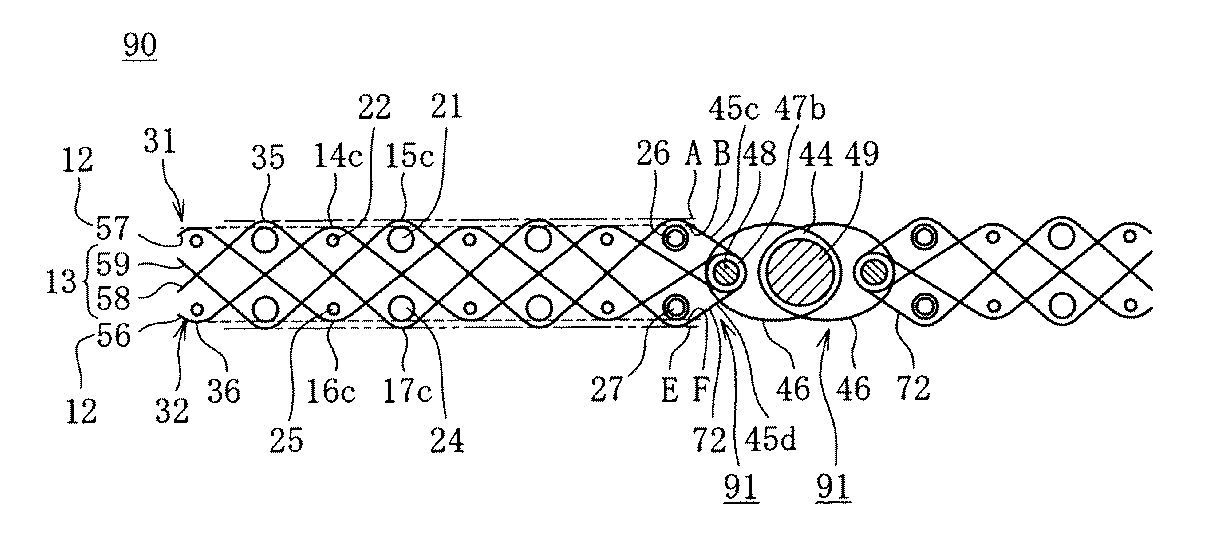
また、図6は、本発明の第6の実施形態における一例に係る継手を有する工業用ベルト90を示した部分断面図である。
【0073】
本発明の第6の実施形態における一例である工業用ベルト90は、前述の第3の実施形態に基づく織成布の構造を有する工業用ベルト60において、織成布を構成する前記第2の経糸13を経糸58,59で構成すると共に、一方の経糸58の延長部を、反接紙面側の先端緯糸27の下から上に捲回するように折り返して一方のループ45dを形成して、その延長部の先端側を先端緯糸26と27の間を通して織成布本体の織組織内へ、すなわち隣り合う第1の経糸12(56,57)における一方の経糸57をカンバスの端部から長さ方向に必要な位置で切断して除去した跡に、織成布本体の織組織と同様の織組織でもって綴り込む。
【0074】
また、前記第1の経糸12における一方の経糸56の延長部を、接紙面側31の先端緯糸26の下から上に捲回するように折り返して一方のループ45cを形成して、その延長部の先端側を先端緯糸26と先端から2番目の緯糸の間を通して織成布本体の織組織内へ、すなわち隣り合う第2の経糸13の一方の経糸59をカンバスの端部から長さ方向に必要な位置で切断して除去した跡に、織成布本体の織組織と同様の織組織でもって綴り込む。
【0075】
そして、各ループ45c,45dにスパイラル線46,46をそれぞれ噛み合わせ、各ループ45c,45dとスパイラル線46,46の共通孔47bに固定芯線48,48を挿通した後、さらに2つのスパイラル線46,46を互いに噛み合わせて成るスパイラル線相互の共通孔44に接合芯線49を挿通して織成布を無端状に接続するための継手91(スパイラルシーム)を、織成布の長さ方向両端部72,72に形成するものである。
なお、工業用ベルト60に代えて、第1実施形態、または第2実施形態に基づく織成布の構造を有する工業用ベルト10,50を用いても良い。
【0076】
上記第4の実施形態ないし第6の実施形態によれば、その長さ方向の両端部を接続して無端状となすための継手をその長さ方向の両端部に有する工業用ベルト70ないし90において、それを駆動する牽引力や張力が集中的に掛かるループ形成経糸、すなわちワープループシーム71における接合用ループ40を形成する経糸18の全て、または、スパイラルシーム81におけるスパイラル線46を噛み合わせるためのループ45aおよび46bのうち、少なくともループ45aを形成する経糸52、あるいは、スパイラルシーム91におけるスパイラル線46を噛み合わせるためのループ45cおよび45dのうち、少なくともループ45cを形成する経糸56が、接紙面側表面35において厚さ方向内側に位置する経糸ナックル14a,14cを形成、または接紙面側表面35において厚さ方向内側に位置する経糸ナックル14cおよび反接紙面側表面36において厚さ方向内側に位置する経糸ナックル16cを形成する第1の経糸12(18、52、56)から成る継手71、81もしくは91となり、特に、第4実施形態のワープループシーム71では、接合用ループ40が全て第1の経糸12(18)だけで形成される。
【0077】
したがって、例えば製紙機械用ドライヤーカンバスや製紙機械用搬送ベルトの場合、摩耗損傷もしくは高温・高湿の条件が重畳しての摩耗損傷によるループ経糸の強力低下や、継手部分の織組織の緩み、荒れ、汚れ物質の付着・堆積などが元での継手部分の表面性の劣化やそれによる紙シートの製品品質への悪影響の危険性を回避することができ、また継手の早期の破断発生を防止することが出来て、ひいては継手の面からもより長期にわたる製品品質の維持が可能となると共に、カンバスや搬送ベルトの使用期間の延長を計ることが可能となる。
【0078】
なお、図4に示した本発明の第4の実施形態における一例に係る継手71において、●印で示した追加の緯糸28は、継手部先端緯糸26および27を巻き込みつつ折り返した後、本体内へ綴り込む緯糸押さえ経糸38と接合用ループ40の根元40aとで囲まれた部分43に挿入する追加の緯糸である。
【0079】
前記追加の緯糸28には、例えばポリエステルやPPSなどの素材から成る、1本の合成繊維モノフィラメントの他、複数本のモノフィラメントから成る撚り糸や、複数本のマルチフィラメントから成る撚り糸が適用できる。また、複数本のPPSモノフィラメントもしくはPPSマルチフィラメントから成る撚り糸を用いれば、継手部分の耐熱性が向上し寿命延長が図れるので好ましい。
【0080】
それら追加の緯糸28を挿入すれば、緯糸押さえ経糸38が先端緯糸26,27を捲回する端部72において、接紙面側表面35や反接紙面側表面36から突出して、紙シートへマークを発生させるような状態が生じるのを防止したり、先端緯糸26および27の抜け出しを防止したり出来るため、好ましい。
【0081】
さらに、◎印で示した継手部先端緯糸26,27、および/または前記●印で示した追加の緯糸28に、上記のモノフィラメント撚り糸またはマルチフィラメント撚り糸、特にはPPSマルチフィラメント撚り糸を適用するのが、より一層効果的である。また、用途によっては、追加の緯糸28を挿入せず、先端緯糸26および/または27だけに、上記モノフィラメント撚り糸またはマルチフィラメント撚り糸を使用することも可能である。
【0082】
また、図5に示した本発明の第5の実施形態における一例に係る継手を有する工業用ベルト80において、◎印で示した継手部先端緯糸26,27に、上記のモノフィラメント撚り糸またはマルチフィラメント撚り糸、特にはPPSマルチフィラメント撚り糸を適用すれば、紙シートへのマーク発生や先端緯糸26および27の抜け出しを防ぐことができるため、好ましい。
【0083】
(第7実施形態)
さらに、図7は、第7の実施形態(参考例)における一例に係る継手を有する工業用ベルト100を示した部分断面図である。
【0084】
本発明の第7の実施形態における一例である工業用ベルト100は、前述の第4の実施形態に基づく継手(ワープループシーム)を有する工業用ベルト70(図4)において、前記折り返して接合用ループ40を形成の後、織成布本体の織組織内に綴り込む前記経糸18(18a)を第1の経糸12の一部または全部を用いて形成すると共に、折り返して接合用ループ40を形成の後、織成布本体の織組織内に綴り込む経糸の部分18bが接紙面側31に形成する経糸ナックル14b(図中Hで示す位置にある)が、接紙面側表面35(図中Gで示す位置にある)より織成布の厚さ方向内側に位置する継手の構造を有するものである。
なお、図7では織成布に前記第2の実施形態の構成を有する工業用ベルト50を用いた例を示した。
【0085】
この場合は、前記第1の実施形態、前記第2の実施形態または前記第3の実施形態の工業用ベルト10,50,60において、第1の経糸12および第2の経糸13をそれぞれ18,19および38,39の2本ずつ交互に並べて配置した織組織を用いて、前記折り返して接合用ループ40を形成の後、織成布本体の織組織内に綴り込む経糸18と、織成布の端部72から織成布本体側への必要長さ部分を切断、除去して経糸18が綴り込まれる空隙をつくるための経糸19を、前記2本ずつの第1の経糸12を用いて構成するのが望ましい。
【0086】
(第8実施形態)
また、図8は、本発明の第8の実施形態における一例に係る継手を有する工業用ベルト110示した部分断面図である。
【0087】
本発明の第8の実施形態における一例である工業用ベルト110は、前述の第7の実施形態に基づく継手(ワープループシーム)の構造を有する工業用ベルト100において、第3実施形態の織成布構造を有する工業用ベルト60に代え、さらに、前記折り返して接合用ループ40を形成の後、織成布本体の織組織内に綴り込む経糸の部分18bが反接紙面側32に形成する経糸ナックル16c(図中Jで示す位置にある)も、反接紙面側表面36(図中Iで示す位置にある)より織成布の厚さ方向内側に位置する継手の構造を有するものである。
【0088】
この場合は、前記第3の実施形態の織組織において、第1の経糸12および第2の経糸13をそれぞれ18,19および38,39の2本ずつ交互に並べて配置すると共に、接紙面側31の1本の太い緯糸21と反接紙面側32の1本の太い緯糸24、および接紙面側31の1本の細い緯糸22と反接紙面側32の1本の細い緯糸25とがそれぞれカンバスの厚さ方向に並んで位置する織組織を用いて、前記折り返して接合用ループ40を形成の後、織成布本体の織組織内に綴り込む経糸18と、織成布の端部72から織成布本体側への必要長さ部分を切断、除去して経糸18が綴り込まれる空隙をつくるための経糸19を、前記2本ずつの第1の経糸12を用いて構成するのが望ましい。
【0089】
(第9実施形態)
更に、図9は、第9の実施形態(参考例)における一例に係る継手を有する工業用ベルト120を示した部分断面図である。
【0090】
本発明の第9の実施形態における一例である工業用ベルト120は、前述の第5の実施形態に基づく継手(スパイラルシーム)の構造を有する工業用ベルト80(図5)において、前記スパイラル線46をそれぞれ噛み合わせるためのループ45aを形成する経糸52(52c)を前記第1の経糸12の一部または全部を用いて形成すると共に、該ループ45aを形成する経糸52cにおける折り返してループ45aを形成の後、織成布本体の織組織内に綴り込む部分52dが接紙面側31に形成する経糸ナックル14b(図中Lで示す位置にある)が、接紙面側表面35(図中Kで示す位置にある)より織成布の厚さ方向内側に位置する継手の構造を有するものである。
なお、図9では織成布に前記第2の実施形態の構成を有する工業用ベルト50を用いた例を示した。
【0091】
この場合は、前記第1の実施形態、前記第2の実施形態または前記第3の実施形態の織成布構造を有する工業用ベルト10,50,60において、第1の経糸12および第2の経糸13をそれぞれ52,53および54,55の2本ずつ交互に並べて配置した織組織を用いて、前記折り返してループ45aを形成の後、織成布本体の織組織内に綴り込む経糸52と、織成布の端部72から織成布本体側への必要長さ部分を切断、除去して経糸52が綴り込まれる空隙をつくるための経糸53を、前記2本ずつの第1の経糸12を用いて構成するのが望ましい。
【0092】
(第10実施形態)
図10は、本発明の第10の実施形態における一例に係る継手を有する工業用ベルト130を示した部分断面図である。
【0093】
本発明の第10の実施形態における一例である工業用ベルト130は、前述の第9の実施形態に基づく継手(スパイラルシーム)の構造を有する工業用ベルト120(図9)において、第3実施形態の織成布構造を有する工業用ベルト60に代え、さらに、該ループ45aを形成する経糸52(52c)における折り返してループ45aを形成の後、織成布本体の織組織内に綴り込む経糸52dの部分が反接紙面側32に形成する経糸ナックル16c(図中Nで示す位置にある)も、反接紙面側表面36(図中Mで示す位置にある)より織成布の厚さ方向内側に位置する継手の構造を有するものである。
【0094】
この場合は、前記第3の実施形態の織組織において、第1の経糸12および第2の経糸13をそれぞれ52,53および54,55の2本ずつ交互に並べて配置すると共に、接紙面側31の1本の太い緯糸21と反接紙面側32の1本の太い緯糸24、および接紙面側31の1本の細い緯糸22と反接紙面側32の1本の細い緯糸25とがそれぞれカンバスの厚さ方向に並んで位置する織組織を用いて、前記折り返して接合用ループ40aを形成の後、織成布本体の織組織内に綴り込む経糸52と、織成布の端部72から織成布本体側への必要長さ部分を切断、除去して経糸52が綴り込まれる空隙をつくるための経糸53とを、前記2本ずつの第1の経糸12を用いて構成するのが望ましい。
【0095】
上記第7の実施形態ないしは第10の実施形態によれば、例えば製紙機械用ドライヤーカンバスや製紙機械用搬送ベルトの場合、ワープループシームよりなる継手101,111における前記接合用ループ40を形成する第1の経糸18a、もしくはスパイラルシームよりなる継手121,131における前記ループ45aを形成する第1の経糸52cの、折り返して織成布本体の織組織内に綴り込む部分18bもしくは52dについても、接紙面側表面35もしくは、接紙面側表面35および反接紙面側表面36において、摩耗および熱劣化の防止が施された継手の構造となるので、それら経糸の綴り込む部分18bもしくは52dの強力低下、ならびに、強力低下に起因する継手部分の織組織の緩みがもとでの、前記接合用ループ40や前記ループ45aの伸びの発生および継手部分の表面性の劣化やそれによる紙シートの製品品質への悪影響を防ぐことができ、長期にわたる製品品質の維持やカンバスや搬送ベルトの使用期間の延長がさらに期待できて、好適である。特に、第8の実施形態および第10の実施形態の場合は、前記接合用ループ40もしくは前記ループ45aを形成の後、折り返して織成布本体の織組織内に綴り込む部分18bもしくは52dが、接紙面側表面35および反接紙面側表面36において摩耗および熱劣化の防止が施された継手の構造となるので、好適である。
【0096】
【実施例】
本発明の実施例および比較例を、以下に図および表1,表2を用いて説明する。なお、各図および各表において、TMはポリエステルモノフィラメント、PSは接紙面側、BSは反接紙面側を表す。
【0097】
(実施例1)
実施例1のドライヤーカンバス140を、表1に示す仕様と図1に示す接紙面側が1/3破れ斜文・反接紙面側が3/1破れ斜文織の緯2重織組織で織成し、ヒートセット加工を施して製作した。
【0098】
経糸11は、断面の厚さ方向寸法×幅方向寸法が0.58mm×0.88mmの扁平断面ポリエステルモノフィラメント(TM)から成る第1の経糸12、および、同じ断面寸法の扁平断面PPSモノフィラメント(PPS)から成る第2の経糸13で構成し、経糸密度は29.0本/2.54cmとした。また、経糸11は、図1で( )内にアラビア数字で示した経糸配置順番に基づき、2本ずつの第1の経糸12と2本ずつの第2の経糸13とを緯糸方向に交互に並べて配置した。なお、本実施例と異なり、第1の経糸12および第2の経糸13をそれぞれ1本ずつ交互に配置しても良い。
【0099】
接紙面側31の緯糸の層33には、直径寸法が0.90mmφの円形断面PPSモノフィラメント(PPS)の太い緯糸21と、直径寸法が0.70mmφの円形断面ポリエステルモノフィラメント(TM)の細い緯糸22を使用し、太い緯糸21と細い緯糸22はそれぞれ1本ずつ交互に配置し、接紙面側31の緯糸21,22の密度は12.0本/2.54cmとした。また、反接紙面側32の緯糸の層34には、直径寸法が0.80mmφの円形断面ポリエステルモノフィラメント(TM)の緯糸23を使用し、緯糸23の密度は12.0本/25.4cmとした。すなわち、ドライヤーカンバス140の緯糸密度は12.0本×2/2.54cmである。
【0100】
上記実施例1のドライヤーカンバス140は、第1の経糸12が、接紙面側31の1本の細い緯糸22を内側に織り込んで接紙面側31に経糸ナックル14aを形成すると共に、第2の経糸13が、接紙面側31の1本の太い緯糸21を内側に織り込んで接紙面側31に経糸ナックル15aを形成するように織成して、経糸ナックル14a(図中Bで示す位置にある)が、経糸ナックル15a(図中Aで示す位置にある)により規定される接紙面側表面35よりもカンバスの厚さ方向内側に位置するドライヤーカンバスである。
【0101】
このようにして製作したドライヤーカンバス140は、厚さが3.0mm、通気度が25,050cm3/cm2・minであった。
【0102】
このドライヤーカンバス140を、必要な長さに切断の後、その長さ方向の両端部72,72にカンバスを無端状に接続するための継手(ワープループシーム)71,71を形成した。図4に継手71の部分断面説明図を示す。継手(ワープループシーム)71を形成するにあたっては、2本ずつの第1の経糸12(18,19)のうちの1本の経糸18を延長し、折り返して接合用ループ40を形成の後、織成布本体の織組織内、すなわち隣り合う別の第1の経糸19をカンバスの端部から長さ方向に必要な位置で切断して除去した跡に、織成布本体の織組織と同様の織組織でもって綴り込むと共に、2本ずつの第2の経糸13(38,39)のうちの1本の経糸を緯糸押さえ経糸38として、継手部先端緯糸26および27を継手部先端の外側から捲回して折り返した後、織成布本体の織組織内、すなわち隣り合う別の第2の経糸39をカンバスの端部から長さ方向に適当な位置で切断して除去した跡に、織成布本体の織組織と同様の織組織でもって綴り込み、それらをカンバスの幅方向に繰り返して形成した。また、緯糸押さえ経糸38を継手部先端緯糸26および27の外側から捲回して折り返すに当たり、緯糸押さえ経糸38と接合用ループ40の根元40aとで囲まれた部分43に、追加の緯糸28を挿入した。追加の緯糸28には、直径寸法が0.24mmφの断面円形PPSモノフィラメントを2本ずつ撚り合わせたものを、さらに2本ずつ撚り合わせた撚り糸を用いた。
【0103】
(実施例2)
実施例2のドライヤーカンバス150を、表1に示す仕様と図2に示す接紙面側が1/3破れ斜文・反接紙面側が3/1破れ斜文織の緯2重織組織で織成し、ヒートセット加工を施して製作した。
【0104】
経糸11は、断面の厚さ方向寸法×幅方向寸法が0.58mm×0.88mmの扁平断面ポリエステルモノフィラメント(TM)から成る第1の経糸12および第2の経糸13で構成し、経糸密度は30.0本/2.54cmとした。また、経糸11は、図2で( )内にアラビア数字で示した経糸配置順番に基づき、2本ずつの第1の経糸12と2本ずつの第2の経糸13とを緯糸方向に交互に並べて配置した。なお、本実施例と異なり、第1の経糸12および第2の経糸13をそれぞれ1本ずつ交互に配置しても良い。
【0105】
接紙面側31の緯糸の層33には、直径寸法が0.90mmφの円形断面ポリエステルモノフィラメント(TM)の太い緯糸21と、直径寸法が0.70mmφの円形断面ポリエステルモノフィラメント(TM)の細い緯糸22を使用し、反接紙面側32の緯糸の層34にも、直径寸法が0.90mmφの円形断面ポリエステルモノフィラメント(TM)の太い緯糸24と、直径寸法が0.70mmφの円形断面ポリエステルモノフィラメント(TM)の細い緯糸25を使用した。また、それぞれの層において、太い緯糸21と細い緯糸22および太い緯糸24と細い緯糸25をそれぞれ1本ずつ交互に配置し、接紙面側31の緯糸21,22の密度および反接紙面側32の緯糸24,25の密度は共に12.4本/2.54cmとした。すなわち、ドライヤーカンバス150の緯糸密度は12.4本×2/2.54cmである。
【0106】
また、接紙面側31の1本の太い緯糸21と反接紙面側32の1本の細い緯糸25、ならびに、接紙面側31の1本の細い緯糸22と反接紙面側32の1本の太い緯糸24が、それぞれカンバスの厚さ方向に並ぶように配置した。
【0107】
実施例2のドライヤーカンバス150は、第1の経糸12が、接紙面側31の1本の細い緯糸22を内側に織り込んで接紙面側31に経糸ナックル14bを形成し、かつ、反接紙面側32の1本の太い緯糸24を内側に織り込んで反接紙面側32に経糸ナックル16bを形成すると同時に、第2の経糸13が、接紙面側31の1本の太い緯糸21を内側に織り込んで接紙面側31に経糸ナックル15bを形成し、かつ、反接紙面側32の1本の細い緯糸25を内側に織り込んで反接紙面側32に経糸ナックル17bを形成するように織成して、経糸ナックル14b(図中Bで示す位置にある)が、経糸ナックル15b(図中Aで示す位置にある)により規定される接紙面側表面35よりもカンバスの厚さ方向内側に位置すると共に、経糸ナックル17b(図中Dで示す位置にある)が、経糸ナックル16b(図中Cで示す位置にある)により規定される反接紙面側表面36よりもカンバスの厚さ方向内側に位置するドライヤーカンバスである。
【0108】
このようにして製作したドライヤーカンバス150は、厚さが3.2mm、通気度が27,350cm3/cm2・minであった。
【0109】
このドライヤーカンバス150を、必要な長さに切断の後、その長さ方向の両端部72,72にカンバスを無端状に接続するための継手(ワープループシーム)101,101を、実施例1と同様の方法によって形成した。図7に継手101の部分断面説明図を示す。また、追加の緯糸28には、直径寸法が0.24mmφの断面円形ポリエステルモノフィラメント(TM)を2本ずつ撚り合わせたものを、さらに2本ずつ撚り合わせた撚り糸を用いた。
【0110】
(実施例3)
実施例3のドライヤーカンバス160を、表1に示す仕様と図3に示す、接紙面側が1/3破れ斜文・反接紙面側が3/1破れ斜文織の緯2重織組織で織成し、ヒートセット加工を施して製作した。
【0111】
経糸11は、実施例2と同じ断面寸法の扁平断面ポリエステルモノフィラメント(TM)から成る第1の経糸12および第2の経糸13で構成し、経糸密度は29.5本/2.54cmとした。また、経糸11は、図3で( )内にアラビア数字で示した経糸配置順番に基づき、2本ずつの第1の経糸12と2本ずつの第2の経糸13とを緯糸方向に交互に並べて配置した。なお、本実施例と異なり、第1の経糸12および第2の経糸13をそれぞれ1本ずつ交互に配置しても良い。
【0112】
接紙面側31の緯糸の層33には、直径寸法が0.90mmφの円形断面ポリエステルモノフィラメント(TM)の太い緯糸21と、直径寸法が0.70mmφの円形断面ポリエステルモノフィラメント(TM)の細い緯糸22を使用し、反接紙面側32の緯糸の層34にも、直径寸法が0.90mmφの円形断面ポリエステルモノフィラメント(TM)の太い緯糸24と、直径寸法が0.70mmφの円形断面ポリエステルモノフィラメント(TM)の細い緯糸25を使用した。また、それぞれの層において、太い緯糸21と細い緯糸22および太い緯糸24と細い緯糸25をそれぞれ1本ずつ交互に配置し、接紙面側31の緯糸21,22の密度および反接紙面側32の緯糸24,25の密度は共に12.5本/2.54cmとした。すなわち、ドライヤーカンバス160の緯糸密度は、12.5本×2/2.54cmである。
【0113】
また、接紙面側31の1本の太い緯糸21と反接紙面側32の1本の太い緯糸24、ならびに、接紙面側31の1本の細い緯糸22と反接紙面側32の1本の細い緯糸25が、それぞれカンバスの厚さ方向に並ぶように配置した。
【0114】
実施例3のドライヤーカンバス160は、前述の実施例2と異なり、第1の経糸12が、接紙面側31の1本の細い緯糸22を内側に織り込んで接紙面側31に経糸ナックル14cを形成し、かつ、反接紙面側32の1本の細い緯糸25を内側に織り込んで反接紙面側32に経糸ナックル16cを形成すると同時に、第2の経糸13が、接紙面側31の1本の太い緯糸21を内側に織り込んで接紙面側31に経糸ナックル15cを形成し、かつ、反接紙面側32の1本の太い緯糸24を内側に織り込んで反接紙面側32に経糸ナックル17cを形成するように織成して、経糸ナックル14c(図中Bで示す位置にある)が、経糸ナックル15c(図中Aで示す位置にある)により規定される接紙面側表面35よりもカンバスの厚さ方向内側に位置すると共に、経糸ナックル16c(図中Fで示す位置にある)が、経糸ナックル17c(図中Eで示す位置にある)により規定される反接紙面側表面36よりもカンバスの厚さ方向内側に位置するドライヤーカンバスである。
【0115】
このようにして製作したドライヤーカンバス160は、厚さが3.2mm、通気度が26,750cm3/cm2・minであった。
【0116】
このドライヤーカンバス160を、必要な長さに切断の後、その長さ方向の両端部72,72にカンバスを無端状に接続するための継手(ワープループシーム)111、111を、実施例1と同様の方法によって形成した。図8に継手111の部分断面説明図を示す。また、追加の緯糸28には、直径寸法が0.24mmφの断面円形ポリエステルモノフィラメントを2本ずつ撚り合わせたものを、さらに2本ずつ撚り合わせた撚り糸を用いた。
【0117】
(実施例4)
実施例4のドライヤーカンバス170を、表1に示す仕様と図3に示す接紙面側が1/3破れ斜文・反接紙面側が3/1破れ斜文織の緯2重織組織で織成し、ヒートセット加工を施して製作した。
【0118】
実施例4のドライヤーカンバス170は、実施例3のドライヤーカンバス160において、接紙面側31の細い緯糸22および反接紙面側32の細い緯糸25に直径寸法が0.80mmφの円形断面ポリエステルモノフィラメント(TM)を用いると共に、経糸密度を29.4本/2.54cm、接紙面側31の緯糸21,22の密度および反接紙面側32の緯糸23,24の密度を共に11.5本/2.54cm(すなわち、カンバスの緯糸密度は11.5本×2/2.54cm)とし、その他は同じく製作したものである。
【0119】
このようにして製作したドライヤーカンバス170は、厚さが3.3mm、通気度が28,800cm3/cm2・minであった。
【0120】
このドライヤーカンバス170を、必要な長さに切断の後、その長さ方向の両端部72,72にカンバスを無端状に接続するための継手(スパイラルシーム)81,81を形成した。図5に継手81の部分断面説明図を示す。
【0121】
継手(スパイラルシーム)81を形成するにあたっては、2本ずつの第1の経糸12(52,53)のうちの1本の経糸52を延長し、折り返してループ45aを形成し、このループ45aにスパイラル線46をそれぞれ噛み合わせ、この噛み合い部の共通孔47aに固定芯線48を挿通した後、織成布本体の織組織内、すなわち隣り合う別の第1の経糸53をカンバスの端部から長さ方向に必要な位置で切断して除去した跡に、織成布本体の織組織と同様の織組織でもって綴り込むと共に、2本ずつの第2の経糸13(54,55)のうちの1本の経糸54が、接紙面側31および反接紙面側32のそれぞれの継手部先端緯糸26および27を外側から捲回するように折り返してループ45bを形成し、このループ45bにもスパイラル線46をそれぞれ噛み合わせ、噛み合い部の共通孔47aに固定芯線48を挿通した後、織成布本体の織組織内、すなわち隣り合う別の第2の経糸55をカンバスの端部から長さ方向に適当な位置で切断して除去した跡に、織成布本体の織組織と同様の織組織でもって綴り込み、それらをカンバスの幅方向に繰り返して形成した。固定芯線48には、直径寸法が1.00mmφの断面円形ポリエステルモノフィラメントを用いた。
【0122】
(比較例1)
比較例1のドライヤーカンバス180を、表2に示す仕様と図11に示す接紙面側が1/3破れ斜文・反接紙面側が3/1破れ斜文織の緯2重織組織で織成し、ヒートセット加工を施して製作した。
【0123】
経糸11は、実施例1と同じ断面寸法の扁平断面ポリエステルモノフィラメント(TM)で構成し、経糸密度は29.5本/2.54cmとした。
【0124】
接紙面側31の緯糸の層33および反接紙面側32の緯糸の層34には、すべて同じ太さの、直径寸法が0.80mmφの円形断面ポリエステルモノフィラメント(TM)の緯糸23を使用し、緯糸密度は12.3本×2/2.54cmとした。
【0125】
このようにして製作したドライヤーカンバス180は、厚さが3.0mm、通気度が24,700cm3/cm2・minであった。
【0126】
このドライヤーカンバス180を、必要な長さに切断の後、その長さ方向の両端部72,72にカンバスを無端状に接続するための継手(ワープループシーム)181,181を形成した。図12に継手181の部分断面説明図を示す。継手(ワープループシーム)181を形成するにあたっては、4本ずつの第1の経糸11のうちの1本を延長し、折り返して接合用ループ40を形成の後、織成布本体の織組織内、すなわち4本ずつの経糸11のうちの隣り合う他の1本の経糸をカンバスの端部から長さ方向に適当な位置で切断して除去した跡に、織成布本体の織組織と同様の織組織でもって綴り込むと共に、4本ずつの経糸11のうちの別の1本を接紙面側31および反接紙面側32のそれぞれの最も先端の緯糸の外側から捲回して折り返した後、織成布本体の織組織内、すなわち4本ずつの経糸11のうち隣り合う残りの1本の経糸をカンバスの端部から長さ方向に必要な位置で切断して除去した跡に、織成布本体の織組織と同様の織組織でもって綴り込み、それらをカンバスの幅方向に繰り返して形成した。
【0127】
なお、前述した通気度は、JIS L1096−1999 一般織物試験方法におけるフラジール形法に準拠した測定装置を用い、規定の測定面積を有する空気孔を介して規定の圧力(水柱125Pa)のもとで単位時間に試験片を通過する空気量(cm3/cm2・min)を測定したものである。
【0128】
【表1】
【表2】
(織物表面に表出する経糸ナックルの差の確認)
上記の実施例2〜3および比較例1の各ドライヤーカンバスの接紙面側(PS)および反接紙面側(BS)の表面に表出する経糸ナックルの差を確認する試験を、下記の要領で行った。
【0131】
すなわち、実施例2、実施例3および比較例1の各ドライヤーカンバ150,160および180から試料を切り取り、それぞれの試料片における表面の状態を、インストロン5568型万能試験装置を用いて、試料片の上から圧力測定フィルム(富士プレスケール;富士写真フィルム株式会社製)を介して、加圧ヘッド(円形端面、表面積0.002m2)を、加圧力3,920N
(単位面積当たり1,960kPa)、加圧時間30秒の加圧条件で押し付けて、圧力測定フィルムの接触点を発色させて、接紙面側および反接紙面側の表面の状況を確認した。
【0132】
図13に、その試験結果を示す。
図13において、(A)は実施例2の接紙面側表面(PS)の状況、(B)は実施例2の反接紙面側(BS)の状況、(C)は実施例3の接紙面側表面(PS)の状況、(D)は実施例3の反接紙面側(BS)の状況、(E)は比較例1の接紙面側表面(PS)の状況を示したものである。なお、各図中の黒点が、表出する経糸ナックルが接触することにより発色した接触部である。また、表裏対象の織組織である比較例1では、反接紙面側表面(BS)の状況が接紙面側表面(PS)の状況とほぼ同じであったので、接紙面側表面(PS)の状況だけを示した。
【0133】
図13(A)および図13(C)を図13(E)と比較して明らかなように、実施例2(A)および実施例3(C)では、比較例1(E)に比べて接紙面側表面(PS)に表出する経糸ナックルの数が緯糸方向に1/2に減少している。また、図13(B)および図13(D)を図13(E)と比較すると、実施例2(B)および実施例3(D)では、比較例1(E)に比べて反接紙面側表面(BS)に表出する経糸ナックルの数が緯糸方向に1/2に減少している。
【0134】
このように本発明の実施例2および3では、接紙面側または、接紙面側および反接紙面側の表面に表出する経糸ナックルの数が比較例1より大幅に減少するので、汚れ物質が経糸と緯糸の交錯点付近に多く付着し経時的に堆積するのを防止することが可能となる。さらに、接紙面側または接紙面側および反接紙面側の表面に経糸ナックルが表出しない第1の経糸12、および、反接紙面側の表面に経糸ナックルが表出しない第2の経糸13の摩耗損傷を防止して、経糸強力の低下を防止することが可能となる。
【0135】
また、実施例1〜4では、経糸の密度が29.0本/2.54cm〜30.0本/2.54cmに対し、緯糸の密度が11.5本×2/2.54cm〜12.5本×2/2.54cmと粗くして、経糸12,13と緯糸21,22,24,25との交錯点を少なくした上に、太さの異なる緯糸21,緯糸22および緯糸24,緯糸25を用いて、接紙面側または、接紙面側および反接紙面側の表面に表出する経糸ナックルの数をさらに減少させたので、接紙面側および反接紙面側の表面への汚れ物質の付着が一層減少し、汚れ物質が付着しても洗浄などで容易に除去出来ることが可能となる。
【0136】
(摩耗量の確認)
上記の実施例2、実施例4および比較例1の各ドライヤーカンバスにおける表面の摩耗量を、以下の方法により確認した。
【0137】
すなわち、試験試料として、実施例2のドライヤーカンバス150から試料−1、実施例4のドライヤーカンバス170から試料−2、および比較例1のドライヤーカンバス180から試料−3の各試料片を、各織成布の本体部分から経糸方向を長手にして幅30mm×長さ500mmの大きさで作成した。次に、図14に示すように、各試料片303をそれぞれ、#400番のサンドペーパー302を全周に貼付した周長400mmのローラー301の周囲に、張力加重0.5kg/cmのもとに抱き角度略90°で、試料−1、試料−2もしくは試料−3の接紙面側がサンドペーパー302に接するように取り付けて、ローラー301を300回/毎分の一定速度で回転させ、経過時間1分毎に各試料片303の厚さ寸法を測定して摩耗量を求め、各試料片303における経過時間と摩耗量の関係を確認した。また、各試料片303を取り外した後に、各試験片から採取した経糸の摩耗量を測定した。
【0138】
その結果、各試料片における経過時間1分の時点での摩耗量は、元の厚さに対する割合で表して、試料−1が7.3%、試料−2が5.2%、試料−3が5.0%であり、経過時間10分の時点での摩耗量は、元の厚さに対する割合で表して、試料−1が11.7%、試料−2が9.9%、試料−3が10.0%であった。
【0139】
また、各試料片における経過時間1分から10分の間における1分毎の摩耗量をもとに、試料−1と試料−3の摩耗量の差を求めた結果は、各経過時間共に試料−1が試料−3よりも0.07mm〜0.08mmだけ摩耗量が多かったが、各経過時間を通じてその差はほぼ一定であった。同様に、試料−2と試料−3の摩耗量の差を求めた結果は、各経過時間共に試料−2が試料−3よりも0.02mm〜0.03mmだけ摩耗量が多かったが、各経過時間を通じてその差はほぼ一定であった。
【0140】
さらに、経過時間10分の時点で各試料片303を取り外した後に、各経糸における接紙面側の経糸ナックルの頂部での摩耗量を調べた結果、各経糸における経糸の厚さ寸法に対する摩耗量の割合は、試料−1では第1の経糸12が46.6%、第2の経糸13が63.8%、試料−2では第1の経糸12が46.6%、第2の経糸13が55.2%であり、試料−3では経糸11が51.7%であった。
【0141】
上記の結果から、接紙面側表面に表出する経糸ナックルの数が少ない実施例2および実施例4のドライヤーカンバス150,170は、同じ断面形状、素材の経糸を同様の織組織でほぼ等しい経糸密度に用い、接紙面側表面に表出する経糸ナックルの数がそれらより多い比較例1のドライヤーカンバス180と比べて、摩耗初期の段階では、接紙面側に表出する第2の経糸13の経糸ナックルだけが先に摩耗するため、摩耗初期の段階での摩耗量が幾分多くなり、また、接紙面側の太い緯糸21と細い緯糸22の線径差の大きい実施例2の方が、線径差の小さい実施例4よりも摩耗初期の段階での摩耗量が多くなるが、摩耗初期の段階を過ぎた例えば経過時間1分後以降では、経過時間当たりの摩耗量の増加割合に大きな差異はなく、いずれもほぼ同じ割合で摩耗が進行していくことが判った。
【0142】
さらに、実施例2および実施例4では、接紙面側の経糸ナックルが織成布の厚さ方向内側に位置する第1の経糸12の摩耗量が第2の経糸13よりも少なくなるため、第1の経糸12の磨耗損傷による強力低下を防ぐことが出来ることが判った。さらにまた、実施例2および実施例4における第1の経糸12の摩耗量は、同じ経過時間における比較例1の経糸11の摩耗量よりも少なくなることが判った。
【0143】
したがって、工業用搬送ベルトにおいて、それを駆動する牽引力や張力が集中的に掛かるループ形成経糸に、第1の経糸12の一部または全部を用いて継手を形成すれば、ループ形成経糸の強力低下や、継手部分の表面性の劣化やそれによる紙シートの製品品質への悪影響の危険性を回避することができ、使用期間の延長を計ることが可能となる。
【0144】
なお、上記実施例1〜4の各ドライヤーカンバスは、実使用においても、比較例1のドライヤーカンバスよりも表面への汚れ物質の付着が少なかった。
【0145】
【発明の効果】
本発明によれば、合成繊維モノフィラメントの経糸および緯糸を用いて織成された製紙機械用ドライヤーカンバスや製紙機械用搬送ベルトを始めとする工業用ベルトにおいて、少なくとも接紙面側の緯糸の層に太さの異なる緯糸を交互に配し、経糸を、接紙面側の1本の細い緯糸を内側に織り込んで接紙面側に経糸ナックルを形成すると共に、反接紙面側の1本の緯糸を内側に織り込んで反接紙面側に経糸ナックルを形成する第1の経糸と、接紙面側の1本の太い緯糸を内側に織り込んで接紙面側に経糸ナックルを形成すると共に、反接紙面側の1本の緯糸を内側に織り込んで反接紙面側に経糸ナックルを形成する第2の経糸とで構成して、第1の経糸が接紙面側に形成する経糸ナックルが接紙面側表面よりも織成布の厚さ方向内側に位置するように構成したから、少なくとも接紙面側表面に表出する経糸ナックルの数が減少し、防汚性ならびに洗浄による汚れ物質の除去特性が従来のものより優れると共に、少なくとも接紙面側表面での摩耗損傷、もしくは高温・高湿条件が重畳しての摩耗損傷による経糸強力の低下およびそれが元での汚れ物質の付着・堆積の増加に因る接紙面側の表面性の劣化が防止できて、従来のものより長期にわたって製品品質の維持が可能、かつ、形態保持性能や走行性の悪化を防止できて、従来のものより使用期間の延長が可能な機械用ドライヤーカンバスや製紙機械用搬送ベルトおよび各種工業用の搬送ベルトなどの工業用ベルトを実現することが出来る。
【0146】
さらに、本発明によれば、ワープループシームにおける接合用ループもしくはスパイラルシームにおけるスパイラル線を噛み合わせるループを形成する経糸を、接紙面側表面または、接紙面側および反接紙面側表面における摩耗損傷の防止を施した前記第1の経糸で構成したから、前記ループを形成する経糸の強力低下に起因する継手における早期の破断発生の危険性、および継手部分の織組織の緩み,荒れ,汚れ物質の付着・堆積などがもとでの継手部分の表面性の劣化やそれによる紙シートの製品品質への悪影響の危険性を回避することができて、継手の面からも、従来のものに比べてより長期にわたる製品品質の維持と、工業用ベルトの使用期間の延長を図ることが可能となる。
【0147】
加えて、本発明によれば、前記第1の経糸および前記第2の経糸における少なくとも一方の経糸に耐熱性および/または耐摩耗性の優れる素材から成る合成繊維モノフィラメントを用いたから、および/または、少なくとも接紙面側の緯糸の層における少なくとも太い緯糸に耐熱性および/または耐摩耗性の優れる素材から成る合成繊維モノフィラメントを用いたから、耐熱性および/または耐摩耗性の上記向上効果がさらに強化される。
【0148】
また、本発明によれば、少なくとも接紙面側おける緯糸の層の少なくとも太い緯糸に、耐熱性および防汚性に優れる素材から成る合成繊維モノフィラメントを用いたから、上記防汚性の向上効果がさらに顕著となる。
【図面の簡単な説明】
【図1】 本発明の第1の実施形態(参考例)における一例に係る工業用ベルトの織組織を示した経糸方向の断面説明図である。
【図2】 本発明の第2の実施形態(参考例)における一例に係る工業用ベルトの織組織を示した経糸方向の断面説明図である。
【図3】 本発明の第3の実施形態における一例に係る工業用ベルトの織組織を示した経糸方向の断面説明図である。
【図4】 本発明の第4の実施形態(参考例)における一例に係る工業用ベルトの継手を示した部分断面説明図である。
【図5】 本発明の第5の実施形態(参考例)における一例に係る工業用ベルトの継手を示した部分断面説明図である。
【図6】 本発明の第6の実施形態における一例に係る工業用ベルトの継手を示した部分断面説明図である。
【図7】 本発明の第7の実施形態(参考例)における一例に係る工業用ベルトの継手を示した部分断面説明図である。
【図8】 本発明の第8の実施形態における一例に係る工業用ベルトの継手を示した部分断面説明図である。
【図9】 本発明の第9の実施形態(参考例)における一例に係る工業用ベルトの継手を示した部分断面説明図である。
【図10】 本発明の第10の実施形態における一例に係る工業用ベルトの継手を示した部分断面説明図である。
【図11】 本発明の比較例に係る工業用ベルトの織組織を示した経糸方向の断面説明図である。
【図12】 本発明の比較例に係る継手を有する工業用ベルトの部分断面説明図である。
【図13】 本発明の実施例および比較例の工業用ベルトについて織物表面に表出する経糸ナックルの差を確認する試験で、表出する経糸ナックルが接触することにより発色した接触部を黒点で示す図で、
(A)は実施例2の接紙面側表面の状況、
(B)は実施例2の反接紙面側表面の状況、
(C)は実施例3の接紙面側表面の状況、
(D)は実施例3の反接紙面側表面の状況、
(E)は比較例の接紙面側表面の状況を示す。
【図14】 本発明および比較例の工業用ベルトについて表面の摩耗量の確認試験に用いた装置の模式図である。[0001]
BACKGROUND OF THE INVENTION
The present invention relates to improvements in industrial belts used for paper making machine dryer canvases, paper making machine transport belts, and various industrial transport belts.
[0002]
[Prior art]
In general, industrial belts are used to transport various industrial products and processed products. For example, in finishing processes such as paper machine dry parts, calendar parts, and coating processes, dryer canvases and paper machines for paper machines are used. A machine conveyor belt is used. Also known are net conveyors and conveyor belts in drying and heat treatment processes for fiber products and processed products such as non-woven fabric thermal bonding processes and food products and processed products.
[0003]
For example, in a paper machine, the gummy pitch of the sticky oil contained in the stock material at the dry part of the paper machine, or the size liquid or coating liquid that is a papermaking paste becomes dirty, and the dryer canvas Adhere to the surface. When this dirt accumulates over time, the canvas is clogged, and the air permeability is remarkably lowered so that its drying action cannot be exhibited. Therefore, the dirt in the paper making dryer canvas has been a serious problem.
[0004]
In order to prevent dirt from adhering to the surface of the canvas, and to easily remove the dirt even if the dirt adheres, a coarse porous paper-making dryer canvas woven into a single-layer plain weave structure is used, for example. 58-55280.
[0005]
This dryer for paper making uses a synthetic resin monofilament with a diameter of 0.6 mmφ to 1.2 mmφ as a warp and a weft, respectively, and a super open mesh with a warp density and a weft density of 8 to 15 pieces / 2.54 cm. Woven into a single-layer plain weave structure, and subjected to heat setting under tension so that both warp and weft are curved and fixed to the same degree at the structure point, and the air permeability is 30,000 cm Three /cm 2 ・ Min or more.
[0006]
This paper-making dryer canvas is a single layer plain weave structure, and its warp density and weft density are both 8-15 yarns / 2.54 cm, which is extremely coarse, so the entanglement point between the warp and the weft in contact with the wet paper (Intersection points) are reduced, dirt substances are less likely to adhere to the canvas surface, and the eyes are rough, so even if dirt substances adhere, they can be easily removed by washing, brushing, etc. It has excellent soiling properties.
[0007]
By the way, in recent years, from the viewpoint of environmental protection and resource reuse, as waste paper has started to be used in large quantities as a raw material for papermaking, there are many sticky substances such as natural rubber and synthetic rubber contained in waste paper on the canvas surface. The phenomenon of adhering has occurred. Therefore, antifouling measures in the dryer canvas are being demanded more severely than in the past, and the dryer canvas disclosed in the aforementioned Japanese Utility Model Publication No. 58-55280 is difficult to sufficiently respond to the severe requirements. That was the current situation.
[0008]
Therefore, the present applicant examined the cause of the adhesion of dirt substances in the dryer canvas and the antifouling measures based on the situation described above, and the dirt on the canvas surface due to dirt substances such as adhesive substances is mainly warp yarns. Paying attention to the result of adhering from the tangling point (intersection point) of the weft and accumulating over time, as an antifouling measure, the entanglement point (intersection) of warp and weft on the canvas surface in contact with the wet paper In order to reduce the entanglement point (intersection point) of warp and weft while maintaining strength and dimensional stability without reducing the density of warp and weft, By changing the thickness of the weft yarns without changing the density of the warp and weft yarns, the thick weft yarns and the thin weft yarns are arranged alternately to reduce the entanglement points (intersection points) in contact with the wet paper, and the dryer canvas Powerful and low dimensional Have found that the sex is good, it proposes a papermaking drier canvas disclosed in Japanese Patent Laid-Open No. 9-310291.
[0009]
This paper machine dryer canvas is a paper machine dryer canvas in which a synthetic resin monofilament having a circular cross-section is woven into a single-layer plain weave structure as warps and wefts. Monofilaments having different thicknesses are alternately arranged on the wefts. It is characterized by being woven. Further, the thickness of the synthetic resin monofilament is preferably in the range of 0.6 mm to 1.2 mmφ in diameter, and a polyester monofilament is disclosed as a desirable synthetic resin monofilament.
[0010]
This paper-making dryer canvas can reduce the tangling points (intersection points) between the warp and weft that come into contact with the wet paper on the canvas surface. It is a dryer canvas that has a remarkable effect on prevention and has excellent strength and dimensional stability.
[0011]
[Problems to be solved by the invention]
By the way, in recent years, as described above, from the viewpoint of environmental protection and resource reuse, the amount of used paper as a papermaking raw material has been increasing. Especially in heavy papermaking, such as paperboard and cardboard, Operation at a ratio of 100% is also very common. As a result, the user's request for countermeasures against adhesion / deposition of the above-mentioned dirt substance to the canvas texture structure or improvement of the cleaning performance of the adhered dirt is, for example, compared with the time of filing of the aforementioned Japanese Utility Model Publication No. 58-55280. It ’s getting much harder.
[0012]
In the above papermaking, which has a very high ratio of used paper raw materials, there are more paper dust stains due to fine fibers in the raw materials than in the case of other papermaking, and the amount of internal additives and coating agents used is also large. Since there are a lot of items, etc., the amount of dirt adhered to and deposited on the surface of the dryer canvas or near the intersection of the warp and weft is large, and the dirt is interposed between the paper sheet and the canvas. For this reason, the surface of the dryer canvas, particularly the paper contact surface side surface, is also a factor of wear.
[0013]
Also, in paper machine calendar parts and finishing processes such as the coating process, paper dust, internal additives such as white pitch, and contaminants such as coating agents are interposed between the sheet and the canvas or the conveyor belt. In this situation, friction with the paper sheet occurs and wear due to contact with the doctor blade or the like is also superimposed, so that wear on the surface of the canvas or the conveyor belt, particularly the surface on the paper contact surface side, easily proceeds. In addition, wear on the side of the paper that comes back (machine side) due to contact with a mechanical device such as a guide roll also occurs.
[0014]
On the other hand, high-pressure water cleaning and chemical cleaning methods are generally used as an on-machine removal method for contaminated substances deposited and deposited on the dryer canvas, but in order to scrape off the deposits on the canvas surface, In some cases, a net or scraper knitted with spiral wires is installed and used. In such a case, the wear on the canvas surface is further increased by contact with them, so that the surface of the canvas surface, particularly the paper contact surface side surface, is further improved. Improvement of wear resistance, and maintenance of strength and form retention under conditions that are subject to wear damage are also required in conjunction with the improvement of antifouling properties and cleanability.
[0015]
Usually, a dryer canvas is wound endlessly between a plurality of dryer cylinders and rollers and attached to a paper machine to move. Therefore, it is necessary to connect both ends in the length direction to make it endless. There are joints at both ends of the canvas.
[0016]
The joint is formed by extending a part of the warp constituting the canvas fabric at both ends of the canvas, folding back to form a joining loop, and then binding the loop into the canvas body. A so-called warp loop seam is generally used in which a joining core wire is inserted into a common hole formed by connecting the canvases in an endless manner.
[0017]
As another joint, at both ends of the canvas, a part of the warp constituting the canvas fabric is extended and folded to form a loop, and the spiral wire is meshed with the loop, and the common hole of the meshing portion is After inserting the fixed core wire into the canvas body, it is bound in the canvas body, and further, the canvas is connected endlessly by inserting the joint core wire into the common hole of the spiral wires formed by meshing the two spiral wires with each other. Spiral seams are common.
[0018]
Then, the traction force and tension for driving the canvas are concentrated on the warp forming the joining loop and the warp forming the loop for engaging the spiral wire, and the joining loop and the spiral wire are engaged. Since the loop for forming the canvas fabric is usually formed by a part of the warp constituting the canvas fabric, for example, 1/2 or 1/4 warp, when the strength decreases due to wear damage of the warp, There is a high risk that the joint will be broken early and the canvas will become unusable. In addition, depending on the properties of the material such as polyester, the strength reduction due to thermal degradation under high temperature and high humidity conditions may also be affected.
[0019]
Therefore, measures for wear of the warp forming the above-mentioned joining loop or the warp forming the loop for meshing the spiral wire, and measures for lowering the warp strength under conditions of thermal degradation and wear damage, It has become particularly important for extending the service life (extending the service period).
[0020]
On the other hand, monofilaments with large wire diameters and large cross-sectional areas are used for warp yarns to increase the warp thickness dimension and single yarn strength, reduce the degree of influence of wear on warp strength reduction, and prevent early breakage accidents. Although measures such as preventing occurrence have been made, even in that case, the warp wear damage of the above-mentioned joining loop and the loop for meshing the spiral wire and the strength reduction due to thermal degradation are lower than the other warp However, it has not yet reached the effect of decreasing.
[0021]
Accordingly, the present invention is an industrial belt used for transporting various industrial products and processed products, for example, a dryer canvas for a papermaking machine and a transport belt for a papermaking machine. In addition to excellent removal performance, it is intended to prevent warp wear on the surface of the fabric, especially on the side of the paper contact surface that contacts the wet paper. The purpose of the present invention is to provide industrial belts such as dryer canvases for papermaking machines, transport belts for papermaking machines, and various industrial transport belts, which have a longer service life than conventional ones by preventing the warp strength of the warp from being reduced. .
[0022]
[Means for Solving the Problems]
As a technical means for achieving the above object, the present invention provides an industrial belt comprising a synthetic fiber monofilament warp and a woven fabric using a weft, wherein the weft layer is a weft layer on the paper contact side. And at least two weft layers including a weft layer on the side opposite the paper surface, Said Weft layer on the paper contact side And a layer of the weft on the side opposite the paper But Both Wefts with different thicknesses are arranged alternately, and the warp is one thin weft on the paper contact side. And one thin weft on the side facing the paper Woven inward, paper contact side And anti-paper side A first warp forming a warp knuckle and one thick weft on the paper contact side And one thick weft on the side facing the paper Woven inward, paper contact side And anti-paper side Having a second warp forming a warp knuckle, and the first warp is on the paper contact surface side And anti-paper side The warp knuckle that is formed into The second warp is defined by a warp knuckle formed on the paper contact surface side and the reverse paper contact surface side. Paper side surface And the reverse side surface Located on the inner side in the thickness direction of the woven fabric, and further, the second warp has better heat resistance and / or wear resistance than the first warp. The A synthetic fiber monofilament made of a material is used (claim 1).
[0023]
Reference example The weft layers on the paper-contacting surface side and the weft layers on the counter-contacting surface side are alternately arranged with wefts having different thicknesses, and the second warp is Anti The warp knuckle formed on the paper contact side Anti It is located in the thickness direction inner side of a woven fabric rather than the paper-contacting surface side surface.
[0024]
The present invention as mentioned above, The weft layer on the paper-contacting surface side and the weft layer on the anti-paper-contacting surface side are formed by alternately arranging wefts having different thicknesses, and the warp knuckle formed by the first warp on the anti-contacting surface side is It is located on the inner side in the thickness direction of the woven fabric with respect to the paper contact surface side surface. 1 ).
[0025]
Reference example The weft layer on the side of the paper-contacting side is composed of wefts of equal thickness, and the warp knuckle formed by the first warp on the side of the paper-contacting side and the second warp formed on the side of the paper-contacting surface The warp knuckle is made to be flush with the surface on the side opposite the paper surface.
[0026]
The present invention is also more excellent in heat resistance than the first warp in the at least the thick weft in the weft layer on the paper contact surface side among the weft layers on the paper contact surface side and the counter contact paper surface side. The A synthetic fiber monofilament made of a material is used (claim) 2 ).
[0027]
The present invention also provides that at least the thicker wefts in the weft layers on the paper contact surface side among the weft layers on the paper contact surface side and the reverse paper surface side are more heat resistant and antifouling than the first warp. Excellent The A synthetic fiber monofilament made of a material is used (claim) 3 ).
[0028]
According to the present invention, the industrial belt extends a part of the warp constituting the woven fabric and folds back to form a joining loop, which is then bound into the woven structure of the woven fabric body. An industrial belt having joints for connecting a woven fabric endlessly by inserting a joining core wire into a common hole formed by meshing loop rows with each other at both ends in the longitudinal direction of the woven fabric, After forming the loop for joining by folding, the warp to be bound into the woven structure of the woven fabric main body is formed using a part or all of the first warp. 4 ).
[0029]
The present invention is also a warp knuckle formed by a portion of a warp to be bound into a woven structure of a woven fabric main body after forming the joining loop by folding, the paper-contacting surface side surface and the paper-contacting surface side surface The warp knuckle is formed on the inner side in the thickness direction from the surface of the woven fabric.
[0030]
According to the present invention, the industrial belt extends a part of the warp constituting the woven fabric and folds to form a loop. The loop is meshed with each of the loops, and a common hole of the meshed portion is formed. After the fixed core wire is inserted, it is bound into the woven fabric of the woven fabric body, and the spliced core wire is inserted into the common hole between the two spiral wires and the woven fabric is endless. An industrial belt having joints for connecting in a longitudinal direction at both ends in the longitudinal direction of the woven fabric, wherein warps forming loops for meshing with the spiral wires are used as one of the first warps. It is formed using a part or all (claim) 5 ).
[0031]
In the present invention, the folding loop is formed to form a joining loop, the spiral wires are respectively meshed with the loops, the fixed core wire is inserted into the common hole of the meshing portion, and then the fabric is bound into the woven tissue of the woven fabric body. A warp knuckle formed by a warp portion to be inserted, wherein the warp knuckle formed on the paper contact surface side surface and the reverse paper contact surface side surface is located on the inner side in the thickness direction from the surface of the woven fabric.
[0032]
DETAILED DESCRIPTION OF THE INVENTION
The term “industrial belt” in the present invention is a broad term that collectively refers to a dryer canvas for a paper machine, a conveyor belt for a paper machine, and various industrial conveyor belts made of woven fabric using synthetic fiber monofilament warp and weft. belongs to.
[0033]
In the present invention, since synthetic fiber monofilament is used for warp and weft, it is possible to prevent adhesion and entry of dirt substances to the surface and inside of the yarn, compared to the case of using multifilament or spun yarn. It also improves the removal performance of adhered and accumulated dirt substances.
[0034]
The above-mentioned “synthetic fiber monofilament” means heat resistance performance such as polyester such as PET (polyethylene terephthalate), PBT (polybutylene terephthalate), PEN (polyethylene naphthalate), or PPS (polyphenylene sulfide), PEEK (polyether ether ketone). Synthetic fiber monofilament mainly composed of good materials. Further, for example, monofilaments containing antifouling materials such as PTFE (polytetrafluoroethylene) monofilaments and monofilaments containing fluorine-based resins are included.
[0035]
The weaving structure is a weaving structure in which the weft layer has at least two weft layers including a weft layer on the paper-contacting surface side and a weft layer on the opposite paper-contacting surface side. Based on a weft double weave structure consisting of a weft layer on the paper-contacting surface side and a weft layer on the anti-paper-contacting surface side. For example, in order to lower the air permeability setting range and increase the rigidity of the fabric, Between the weft layer on the paper contact side and the weft layer on the side opposite the paper surface, a weft 2.5 or weft triple weave structure having one additional weft layer may be used. . From the viewpoint of preventing adhesion of paper dust and dirt substances and removing attached dirt, it is preferable to use a synthetic fiber monofilament for the added weft layer.
[0036]
Also, on the paper-contacting side and the counter-contacting surface side, a warp knuckles are formed by weaving one weft inward, and a portion where the warp intersects with the weft using a weave structure that does not form a warp float (crossing) It is preferable to increase the degree of contact between the warp and the weft at the point) to improve the rigidity, form retention and running stability of the woven structure.
[0037]
(First embodiment)
FIG. 1 shows a first embodiment. (Reference example) It is sectional drawing of the warp direction which showed the woven structure of the industrial feeding belt 10 which concerns on an example in.
[0038]
In the industrial belt 10 as an example in the first embodiment of the present invention, the
[0039]
The
[0040]
Furthermore, as a woven fabric using the
[0041]
With this configuration, the warp knuckle exposed on the paper-contacting
[0042]
In addition, since the occurrence of wear on the paper contact
[0043]
Furthermore, the degree of thermal degradation of the
[0044]
Therefore, for example, in the case of a dryer canvas for a papermaking machine or a conveyor belt for a papermaking machine, partial cracking or flaking on the surface of the warp that has been damaged due to wear and reduced strength, and this increases the adhesion and accumulation of dirt substances. The deterioration of the surface property on the paper
[0045]
(Second Embodiment)
Next, FIG. 2 shows a second embodiment. (Reference example) It is sectional drawing of the warp direction which showed the woven structure of the industrial belt 50 which concerns on an example.
[0046]
An industrial belt 50 as an example in the second embodiment of the present invention includes a
[0047]
(Third embodiment)
FIG. 3 is a cross-sectional view in the warp direction showing a woven structure of an industrial belt 60 according to an example of the third embodiment of the present invention.
[0048]
An industrial belt 60 as an example in the third embodiment of the present invention includes a
[0049]
In the belt 50 of the second embodiment shown in FIG. 2, the
[0050]
On the other hand, in the belt 60 of the third embodiment shown in FIG. 3, the
[0051]
1, 2, and 3, the warp arrangement order indicated by Arabic numerals in parentheses is an example, and the embodiment of the present invention is not particularly limited.
[0052]
In the case of the second embodiment and the third embodiment, the number of warp knuckles exposed to the paper contact
[0053]
Particularly in the case of the third embodiment, the wear of the
[0054]
In the practice of the present invention, in addition to the above-described configuration, at least one of the
[0055]
For example, the
[0056]
For example, a polyester monofilament such as PET or PBT is used for the
[0057]
In addition, in the practice of the present invention, the
[0058]
In the practice of the present invention, of the weft layers 33 and 34 on the paper
[0059]
Thereby, the number of warp knuckles exposed to the paper contact
[0060]
It is more effective to use a synthetic fiber monofilament containing an antifouling material for all the
[0061]
In the practice of the present invention, the
[0062]
In addition, as a preferable range of the weft density with respect to the range of the dimensions of the
[0063]
Further, as the
By setting the difference in thickness, the number of warp knuckles exposed on the paper
[0064]
In the practice of the present invention, the preferred size range of the
[0065]
When the cross-sectional dimension of the warp 11 (12, 13) is less than the above range, the rate of decrease in the strength per single yarn of the warp due to the decrease in the cross-sectional area due to wear is large, and it is difficult to maintain the required strength in the warp direction. Therefore it is not suitable. If the above range is exceeded, it will be difficult to achieve the required surface smoothness on the paper-contacting
[0066]
Further, the warp density and the warp filling rate are appropriately selected and determined in consideration of the shape and dimensions of the warp and the strength characteristics of the material within a range that satisfies the object of the present invention. Examples of the range of 50% to 125%, preferably 75% to 110%. The upper limit is that at least the necessary antifouling properties and dirt removal performance can be satisfied, and the lower limit is that the necessary surface smoothness on the paper
[0067]
(Fourth embodiment)
Next, FIG. 4 shows a fourth embodiment. (Reference example) It is a fragmentary sectional view of the
[0068]
The
Instead of the industrial belt 10, industrial belts 50 and 60 having a woven fabric structure based on the second embodiment or the third embodiment may be used.
[0069]
(Fifth embodiment)
Furthermore, FIG. 5 shows a fifth embodiment. (Reference example) It is a fragmentary sectional view of the joint which showed the industrial belt 80 which has the joint which concerns on an example in.
[0070]
An industrial belt 80 as an example in the fifth embodiment of the present invention is a first warp constituting the woven fabric in the industrial belt 10 having the structure of the woven fabric based on the first embodiment described above. 12 is composed of
Instead of the industrial belt 10, industrial belts 50 and 60 having a woven fabric structure based on the second embodiment or the third embodiment may be used.
[0071]
In addition, in FIG. 5, in addition to the
[0072]
(Sixth embodiment)
FIG. 6 is a partial cross-sectional view showing an
[0073]
An
[0074]
In addition, an extension portion of one
[0075]
Then, the
Instead of the industrial belt 60, the industrial belts 10 and 50 having a woven fabric structure based on the first embodiment or the second embodiment may be used.
[0076]
According to the fourth to sixth embodiments, the
[0077]
Therefore, for example, in the case of a dryer canvas for a paper machine or a conveyor belt for a paper machine, the strength of the loop warp is reduced due to wear damage or wear damage caused by the combination of high temperature and high humidity, and the woven structure of the joint part is loosened or roughened. In addition, it is possible to avoid the risk of deterioration of the surface property of the joint part due to the adhesion / deposition of dirt substances and the resulting adverse effect on the product quality of the paper sheet, and also prevent the joint from breaking early. As a result, it is possible to maintain the product quality over a longer period from the viewpoint of the joint, and it is possible to extend the use period of the canvas and the conveyor belt.
[0078]
In addition, in the joint 71 according to the example of the fourth embodiment of the present invention shown in FIG. 4, the
[0079]
For the
[0080]
If these
[0081]
Furthermore, the above-mentioned monofilament twisted yarn or multifilament twisted yarn, particularly PPS multifilament twisted yarn, is applied to the joint
[0082]
Further, in the industrial belt 80 having the joint according to an example of the fifth embodiment of the present invention shown in FIG. 5, the above-mentioned monofilament twisted yarn or multifilament twisted yarn is added to the joint portion
[0083]
(Seventh embodiment)
Further, FIG. 7 shows a seventh embodiment. (Reference example) It is the fragmentary sectional view showing
[0084]
An
In addition, in FIG. 7, the example using the industrial belt 50 which has the structure of the said 2nd Embodiment was shown for the woven fabric.
[0085]
In this case, in the industrial belt 10, 50, 60 of the first embodiment, the second embodiment, or the third embodiment, the
[0086]
(Eighth embodiment)
FIG. 8 is a partial cross-sectional view showing an
[0087]
An
[0088]
In this case, in the woven structure of the third embodiment, the
[0089]
(Ninth embodiment)
Furthermore, FIG. 9 shows a ninth embodiment. (Reference example) It is a fragmentary sectional view showing
[0090]
An
In addition, in FIG. 9, the example using the industrial belt 50 which has the structure of the said 2nd Embodiment was shown for the woven fabric.
[0091]
In this case, in the industrial belt 10, 50, 60 having the woven fabric structure of the first embodiment, the second embodiment, or the third embodiment, the
[0092]
(10th Embodiment)
FIG. 10 is a partial cross-sectional view showing an
[0093]
An
[0094]
In this case, in the woven structure of the third embodiment, the
[0095]
According to the seventh embodiment or the tenth embodiment, for example, in the case of a dryer canvas for a papermaking machine or a conveyor belt for a papermaking machine, the joining
[0096]
【Example】
Examples and Comparative Examples of the present invention will be described below with reference to the drawings and Tables 1 and 2. In each figure and each table, TM represents a polyester monofilament, PS represents a paper contact surface side, and BS represents a paper contact surface side.
[0097]
Example 1
The dryer canvas 140 of Example 1 was woven with a weft double weave structure in which the specifications shown in Table 1 and the paper contact surface side shown in FIG. Made by set processing.
[0098]
The
[0099]
The
[0100]
In the dryer canvas 140 of Example 1, the
[0101]
The dryer canvas 140 thus manufactured has a thickness of 3.0 mm and an air permeability of 25,050 cm. Three /cm 2 ・ It was min.
[0102]
After this dryer canvas 140 was cut to a required length, joints (warp loop seams) 71 and 71 for connecting the canvas endlessly were formed at both ends 72 and 72 in the length direction. FIG. 4 is a partial cross-sectional explanatory view of the joint 71. In forming the joint (warp loop seam) 71, one
[0103]
(Example 2)
The dryer canvas 150 of Example 2 was woven with a weft double weave structure in which the specifications shown in Table 1 and the paper contact surface side shown in FIG. Made by set processing.
[0104]
The
[0105]
The
[0106]
Further, one
[0107]
In the dryer canvas 150 of the second embodiment, the
[0108]
The dryer canvas 150 thus manufactured has a thickness of 3.2 mm and an air permeability of 27,350 cm. Three /cm 2 ・ It was min.
[0109]
After this dryer canvas 150 is cut to a required length, joints (warp loop seams) 101, 101 for connecting the canvas endlessly to both ends 72, 72 in the length direction are connected to the first embodiment. It formed by the same method. FIG. 7 is a partial cross-sectional explanatory view of the joint 101. As the
[0110]
(Example 3)
The dryer canvas 160 of Example 3 was woven with the specifications shown in Table 1 and the weft double weave structure shown in FIG. Made by heat setting.
[0111]
The
[0112]
The
[0113]
Also, one
[0114]
In the dryer canvas 160 of the third embodiment, unlike the second embodiment, the
[0115]
The dryer canvas 160 thus manufactured has a thickness of 3.2 mm and an air permeability of 26,750 cm. Three /cm 2 ・ It was min.
[0116]
After this dryer canvas 160 is cut to a required length, joints (warp loop seams) 111 and 111 for connecting the canvas endlessly to both ends 72 and 72 in the length direction are connected to the first embodiment. It formed by the same method. FIG. 8 is a partial cross-sectional explanatory view of the joint 111. Further, as the
[0117]
Example 4
The dryer canvas 170 of Example 4 was woven with a weft double weave structure in which the specifications shown in Table 1 and the paper contact surface side shown in FIG. Made by set processing.
[0118]
The dryer canvas 170 of Example 4 is the same as that of the dryer canvas 160 of Example 3, except that the circular weft polyester monofilament (TM) having a diameter of 0.80 mmφ is applied to the
[0119]
The dryer canvas 170 thus manufactured has a thickness of 3.3 mm and an air permeability of 28,800 cm. Three /cm 2 ・ It was min.
[0120]
After this dryer canvas 170 was cut to a required length, joints (spiral seams) 81 and 81 for connecting the canvas endlessly were formed at both ends 72 and 72 in the length direction. FIG. 5 is a partial cross-sectional explanatory view of the joint 81.
[0121]
In forming the joint (spiral seam) 81, one
[0122]
(Comparative Example 1)
The
[0123]
The
[0124]
For the
[0125]
The
[0126]
After this
[0127]
In addition, the air permeability mentioned above uses the measuring apparatus based on the fragile form method in JIS L1096-1999 general textiles test method, and is based on the prescription | regulation (water column 125Pa) through the air hole which has a prescription | regulation measurement area. The amount of air that passes through the test piece per unit time (cm Three /cm 2 ・ Min) is measured.
[0128]
[Table 1]
[Table 2]
(Confirmation of the difference in warp knuckle on the fabric surface)
The test for confirming the difference between the warp knuckles appearing on the surface of the paper contacting side (PS) and the side of the paper contacting side (BS) of each dryer canvas of Examples 2 to 3 and Comparative Example 1 is as follows. went.
[0131]
That is, a sample is cut from each of the
The pressure measurement film was pressed under pressure conditions (1,960 kPa per unit area) and a pressurization time of 30 seconds to develop the color of the contact point of the pressure measurement film, and the condition of the surface on the paper contact surface side and the reverse paper contact surface side was confirmed.
[0132]
FIG. 13 shows the test results.
In FIG. 13, (A) shows the situation on the paper contact surface side surface (PS) of Example 2, (B) shows the situation on the reverse paper contact surface side (BS) of Example 2, and (C) shows the paper contact surface of Example 3. The state of the side surface (PS), (D) shows the state of the paper-contacting surface side (BS) of Example 3, and (E) shows the state of the paper-contacting surface side (PS) of Comparative Example 1. In addition, the black dot in each figure is the contact part which color-formed when the warp knuckle which it exposes contacts. Further, in Comparative Example 1 which is the texture of the front and back surfaces, the situation of the paper-contacting surface side (BS) was almost the same as the situation of the paper-contacting surface (PS). Only the situation was shown.
[0133]
As is apparent from the comparison of FIG. 13A and FIG. 13C with FIG. 13E, Example 2 (A) and Example 3 (C) are more in comparison with Comparative Example 1 (E). The number of warp knuckles appearing on the paper-contacting surface (PS) is reduced to ½ in the weft direction. Further, when FIG. 13B and FIG. 13D are compared with FIG. 13E, in Example 2 (B) and Example 3 (D), the surface of the paper is compared with Comparative Example 1 (E). The number of warp knuckles appearing on the side surface (BS) is reduced to ½ in the weft direction.
[0134]
As described above, in Examples 2 and 3 of the present invention, the number of warp knuckles that are exposed on the paper contact surface side or the surface on the paper contact surface side and the reverse paper contact surface side is significantly reduced as compared with Comparative Example 1. It is possible to prevent a large amount from adhering near the intersection of the warp and the weft and accumulating with time. Further, the
[0135]
In Examples 1 to 4, the warp density is 29.0 / 2.54 cm to 30.0 / 2.54 cm, whereas the weft density is 11.5 × 2 / 2.54 cm to 12.2. 5 threads × 2 / 2.54 cm, roughened to reduce the number of intersections between the
[0136]
(Confirmation of wear)
The amount of surface wear in each of the dryer canvases of Examples 2, 4 and Comparative Example 1 was confirmed by the following method.
[0137]
That is, as a test sample, each sample piece of the dryer canvas 150 of Example 2 to Sample-1, the dryer canvas 170 of Example 4 to Sample-2, and the
[0138]
As a result, the amount of wear at the time point of 1 minute in each sample piece is expressed as a percentage of the original thickness, with Sample-1 having 7.3%, Sample-2 having 5.2%, and Sample-3. Is 5.0%, and the amount of wear at the time point of 10 minutes is expressed as a percentage of the original thickness. Sample-1 is 11.7%, Sample-2 is 9.9%, Sample- 3 was 10.0%.
[0139]
Further, the difference between the wear amount of Sample-1 and Sample-3 based on the wear amount per minute during the elapsed time of 1 minute to 10 minutes in each sample piece is the same for each elapsed time. 1 had a larger amount of wear by 0.07 mm to 0.08 mm than Sample-3, but the difference was almost constant throughout each elapsed time. Similarly, the difference in the amount of wear between Sample-2 and Sample-3 was 0.02 mm to 0.03 mm higher than that of Sample-3 for Sample-2 at each elapsed time. The difference was almost constant over time.
[0140]
Further, after removing each
[0141]
From the above results, the dryer canvases 150 and 170 of Example 2 and Example 4 in which the number of warp knuckles appearing on the surface on the paper contact surface side is the same cross-sectional shape, the warp of the material is substantially the same warp with the same woven structure Compared to the
[0142]
Furthermore, in Example 2 and Example 4, the amount of wear of the
[0143]
Therefore, if a joint is formed by using a part or all of the
[0144]
In addition, in the actual use, each dryer canvas of the above Examples 1 to 4 had less adhesion of dirt substances to the surface than the dryer canvas of Comparative Example 1.
[0145]
【The invention's effect】
According to the present invention, in industrial belts such as paper machine dryer canvas and paper machine conveyor belts woven with synthetic fiber monofilament warp and weft, at least the weft layer on the paper contact side is thick. The wefts of different thicknesses are alternately arranged, and the warp is woven into one thin weft on the paper-contacting side to form a warp knuckle on the paper-contacting side, and one weft on the paper-contacting side is inward. A first warp that weaves to form a warp knuckle on the side of the paper-contacting surface, and one thick weft on the side of the paper-contacting surface that weaves inside to form a warp knuckle on the side of the paper-contacting surface, And a second warp that forms a warp knuckle on the side opposite to the paper surface, and the warp knuckle formed by the first warp on the paper side is more woven than the surface of the paper side Located inside the thickness direction As a result, at least the number of warp knuckles appearing on the surface of the paper-contacting surface is reduced, the antifouling property and the removal property of dirt substances by washing are superior to the conventional ones, and the wear on the surface of the paper-contacting surface is at least Decrease in warp strength due to damage or wear damage due to superposition of high temperature and high humidity conditions, and it can prevent deterioration of surface properties on the paper contact side due to increased adhesion and accumulation of dirt materials, Product dryer canvas and paper machine conveyor belt that can maintain product quality over a longer period of time, prevent deterioration of form retention performance and running performance, and extend the usage period compared to conventional ones Industrial belts such as various industrial conveyor belts can be realized.
[0146]
Further, according to the present invention, the warp loop seam forming the joining loop in the warp loop seam or the loop for meshing the spiral line in the spiral seam is used to prevent abrasion damage on the paper contact surface side surface or the paper contact surface side and the reverse paper contact surface side surface. Since the first warp has been prevented, there is a risk of early breakage in the joint due to a decrease in strength of the warp forming the loop, and looseness, roughness, and contamination of the joint portion. It is possible to avoid the deterioration of the surface property of the joint part due to adhesion / deposition and the risk of adversely affecting the product quality of the paper sheet. It becomes possible to maintain the product quality for a longer period and to extend the use period of the industrial belt.
[0147]
In addition, according to the present invention, a synthetic fiber monofilament made of a material having excellent heat resistance and / or wear resistance is used for at least one of the first warp and the second warp, and / or Since the synthetic fiber monofilament made of a material having excellent heat resistance and / or wear resistance is used for at least the thick weft in the weft layer on the paper-contacting surface side, the above-described improvement effect of heat resistance and / or wear resistance is further strengthened. .
[0148]
Further, according to the present invention, since the synthetic fiber monofilament made of a material excellent in heat resistance and antifouling property is used for at least the thick weft of the weft layer on the paper contact surface side, the effect of improving the antifouling property is further remarkable. It becomes.
[Brief description of the drawings]
FIG. 1 is a first embodiment of the present invention. (Reference example) It is sectional explanatory drawing of the warp direction which showed the woven structure of the industrial belt which concerns on an example in.
FIG. 2 is a second embodiment of the present invention. (Reference example) It is sectional explanatory drawing of the warp direction which showed the woven structure of the industrial belt which concerns on an example in.
FIG. 3 is a cross-sectional explanatory view in the warp direction showing a woven structure of an industrial belt according to an example of the third embodiment of the present invention.
FIG. 4 is a fourth embodiment of the present invention. (Reference example) It is a fragmentary sectional explanatory view showing the joint of the industrial belt concerning an example in.
FIG. 5 is a fifth embodiment of the present invention. (Reference example) It is a fragmentary sectional explanatory view showing the joint of the industrial belt concerning an example in.
FIG. 6 is a partial cross-sectional explanatory view showing an industrial belt joint according to an example of a sixth embodiment of the present invention.
FIG. 7 shows a seventh embodiment of the present invention. (Reference example) It is a fragmentary sectional explanatory view showing the joint of the industrial belt concerning an example in.
FIG. 8 is a partial cross-sectional explanatory view showing a joint of an industrial belt according to an example of an eighth embodiment of the present invention.
FIG. 9 shows a ninth embodiment of the present invention. (Reference example) It is a fragmentary sectional explanatory view showing the joint of the industrial belt concerning an example in.
FIG. 10 is a partial cross-sectional explanatory view showing an industrial belt joint according to an example of the tenth embodiment of the present invention.
FIG. 11 is a cross-sectional explanatory view in the warp direction showing a woven structure of an industrial belt according to a comparative example of the present invention.
FIG. 12 is a partial cross-sectional explanatory view of an industrial belt having a joint according to a comparative example of the present invention.
FIG. 13 is a test for confirming the difference in warp knuckles exposed on the surface of the fabric for the industrial belts of Examples and Comparative Examples of the present invention. In the figure shown,
(A) is the situation of the paper contact surface side surface of Example 2,
(B) is the situation of the surface on the side opposite to the paper surface of Example 2,
(C) is the situation on the surface of the paper contact surface of Example 3,
(D) is the situation of the surface on the side opposite to the paper surface of Example 3,
(E) shows the situation of the surface on the paper contact surface side of the comparative example.
FIG. 14 is a schematic view of an apparatus used for a surface abrasion amount confirmation test for industrial belts of the present invention and comparative examples.
Claims (5)
緯糸の層が、接紙面側の緯糸の層および反接紙面側の緯糸の層を含む少なくとも2層の緯糸の層を有し、
前記接紙面側の緯糸の層および前記反接紙面側の緯糸の層が何れも太さの異なる緯糸を交互に配して成り、
経糸が、接紙面側の1本の細い緯糸および反接紙面側の1本の細い緯糸を内側に織り込んで接紙面側および反接紙面側に経糸ナックルを形成する第1の経糸と、接紙面側の1本の太い緯糸および反接紙面側の1本の太い緯糸を内側に織り込んで接紙面側および反接紙面側に経糸ナックルを形成する第2の経糸を有し、
前記第1の経糸が接紙面側および反接紙面側に形成する経糸ナックルが、前記第2の経糸が接紙面側および反接紙面側に形成する経糸ナックルにより規定される接紙面側表面および反接紙面側表面よりも織成布の厚さ方向内側に位置し、
さらに、前記第2の経糸に、前記第1の経糸よりも耐熱性および/または耐摩耗性の優れた素材から成る合成繊維モノフィラメントを用いることを特徴とする工業用ベルト。An industrial belt made of a woven fabric using warp and weft of synthetic monofilament,
The weft layer has at least two weft layers including a weft layer on the paper-contact side and a weft layer on the counter-contact side;
Wherein both layers of contact paper side layer and the counter-contact paper side weft of the weft is made by arranging the different wefts of thicknesses alternately,
A first warp in which a warp is woven into one thin weft on the paper contact surface side and one thin weft on the paper contact surface side to form warp knuckles on the paper contact surface side and the paper contact surface side; and the paper contact surface A second warp that weaves one thick weft on the side and one thick weft on the paper-contacting surface side to form a warp knuckle on the paper- contacting side and the paper- contacting surface side,
Warp knuckle of the first warp is formed on the contact paper side and Hanse' paper side, the second warp contact the paper side surface and anti defined by warp knuckles that form the contact paper side and Hanse' paper side Located on the inner side in the thickness direction of the woven fabric than the surface on the paper-contacting side ,
Furthermore, an industrial belt characterized in that a synthetic fiber monofilament made of a material having heat resistance and / or wear resistance superior to that of the first warp is used for the second warp.
前記折り返して接合用ループを形成の後、織成布本体の織組織内に綴り込む経糸を、前記第1の経糸の一部または全部を用いて形成することを特徴とする請求項1〜3のいずれかに記載の工業用ベルト。The industrial belt extends a part of the warp constituting the woven fabric and folds back to form a joining loop, which is then bound into the woven structure of the woven fabric body, and this loop train is meshed with each other. An industrial belt having joints for connecting the woven fabric endlessly by inserting the joining core wire into the common hole formed at both ends in the longitudinal direction of the woven fabric,
After forming the folded back joining loops claim 1-3, characterized in that the warp Komu spelling in weave woven fabric body is formed by a part or all of the first warp An industrial belt according to any one of the above.
前記スパイラル線をそれぞれ噛み合わせるためのループを形成する経糸を、前記第1の経糸の一部または全部を用いて形成することを特徴とする請求項1〜3のいずれかに記載の工業用ベルト。After the industrial belt extends a part of the warp constituting the woven fabric, turns it back to form a loop, meshes the spiral wire with the loop, and inserts the fixed core wire into the common hole of the meshing portion. In order to connect the woven fabric in an endless manner by inserting the joint core wire into a common hole between the spiral wires, which are bound in the woven structure of the woven fabric main body and further meshed with each other. An industrial belt having joints at both longitudinal ends of a woven fabric,
The industrial belt according to any one of claims 1 to 3 , wherein a warp forming a loop for meshing the spiral lines is formed by using a part or all of the first warp. .
Priority Applications (1)
| Application Number | Priority Date | Filing Date | Title |
|---|---|---|---|
| JP2001294029A JP4772237B2 (en) | 2001-09-26 | 2001-09-26 | Industrial belt |
Applications Claiming Priority (1)
| Application Number | Priority Date | Filing Date | Title |
|---|---|---|---|
| JP2001294029A JP4772237B2 (en) | 2001-09-26 | 2001-09-26 | Industrial belt |
Publications (2)
| Publication Number | Publication Date |
|---|---|
| JP2003096683A JP2003096683A (en) | 2003-04-03 |
| JP4772237B2 true JP4772237B2 (en) | 2011-09-14 |
Family
ID=19115699
Family Applications (1)
| Application Number | Title | Priority Date | Filing Date |
|---|---|---|---|
| JP2001294029A Expired - Fee Related JP4772237B2 (en) | 2001-09-26 | 2001-09-26 | Industrial belt |
Country Status (1)
| Country | Link |
|---|---|
| JP (1) | JP4772237B2 (en) |
Families Citing this family (10)
| Publication number | Priority date | Publication date | Assignee | Title |
|---|---|---|---|---|
| US8696346B2 (en) * | 2008-02-06 | 2014-04-15 | Habasit Ag | Counterband tape |
| KR101009722B1 (en) | 2009-05-07 | 2011-01-19 | 지상빈 | Fabric mat |
| US9382663B2 (en) | 2012-11-13 | 2016-07-05 | Georgia-Pacific Consumer Products Lp | Apparatus, system, and process for determining characteristics of a surface of a papermaking fabric |
| US9062416B2 (en) | 2012-11-13 | 2015-06-23 | Georgia-Pacific Consumer Products Lp | Apparatus, system, and process for determining characteristics of a surface of a papermaking fabric |
| CA2872271C (en) | 2012-12-27 | 2021-02-23 | Toru Egawa | Industrial two-layer fabric |
| US10689796B2 (en) * | 2013-03-14 | 2020-06-23 | Albany International Corp. | Infinity shape coil for spiral seams |
| AU2014349185A1 (en) * | 2013-11-12 | 2016-04-14 | Gpcp Ip Holdings Llc | Process for determining features of a fabric |
| CN106976678B (en) * | 2017-05-17 | 2022-11-08 | 兖矿能源集团股份有限公司 | Flame-retardant aramid fiber conveying belt capable of being mechanically connected |
| JP7015746B2 (en) * | 2018-07-20 | 2022-02-03 | 日本フエルト株式会社 | Industrial textiles |
| CN113265905A (en) * | 2021-05-14 | 2021-08-17 | 王�锋 | Warp and weft special paper and manufacturing method thereof |
Family Cites Families (8)
| Publication number | Priority date | Publication date | Assignee | Title |
|---|---|---|---|---|
| JPH08127992A (en) * | 1994-10-26 | 1996-05-21 | Daiwabo Co Ltd | Joint part of drier canvas |
| US5503196A (en) * | 1994-12-07 | 1996-04-02 | Albany International Corp. | Papermakers fabric having a system of machine-direction yarns residing interior of the fabric surfaces |
| JP3040327B2 (en) * | 1995-05-19 | 2000-05-15 | 敷島紡績株式会社 | Dryer-canvas joint for papermaking and needle canvas for papermaking |
| JP3052245B2 (en) * | 1995-05-19 | 2000-06-12 | 敷島紡績株式会社 | Dryer-canvas joint for papermaking and needle canvas for papermaking |
| JP2962680B2 (en) * | 1996-05-21 | 1999-10-12 | 敷島紡績株式会社 | Dryer canvas for papermaking |
| JP3204939B2 (en) * | 1998-03-19 | 2001-09-04 | 敷島紡績株式会社 | Dryer canvas for papermaking |
| JP3164791B2 (en) * | 1998-03-19 | 2001-05-08 | 敷島紡績株式会社 | Dryer canvas for papermaking |
| US6103067A (en) * | 1998-04-07 | 2000-08-15 | The Procter & Gamble Company | Papermaking belt providing improved drying efficiency for cellulosic fibrous structures |
-
2001
- 2001-09-26 JP JP2001294029A patent/JP4772237B2/en not_active Expired - Fee Related
Also Published As
| Publication number | Publication date |
|---|---|
| JP2003096683A (en) | 2003-04-03 |
Similar Documents
| Publication | Publication Date | Title |
|---|---|---|
| EP1158089B1 (en) | Papermaker's forming fabric | |
| JP5506809B2 (en) | Multi-layer forming fabric for paper machines in which a pair of top CMD yarns and a single top CMD yarn are arranged alternately | |
| EP0905310B1 (en) | Papermaker's fabric | |
| JP6009470B2 (en) | Paper machine fabric | |
| JP4772237B2 (en) | Industrial belt | |
| KR20020071034A (en) | Papermaker's forming fabric with companion yarns | |
| FI88058B (en) | DOUBLE WIRE WITH SEXTON SOLVAR | |
| JP4602955B2 (en) | Three-layer fabric for papermaking | |
| JP3883276B2 (en) | Industrial two-layer fabric with auxiliary weft arranged on the upper layer fabric | |
| JP2004156164A (en) | Industrial multilayer woven fabric | |
| NZ195579A (en) | Multi-layer endless forming fabric for papermaking machine | |
| JP4263201B2 (en) | Dryer canvas for papermaking | |
| FI92080C (en) | Double weave for use as a woven fabric at the wet portion of a paper machine | |
| JP4090587B2 (en) | Industrial fabric | |
| JP4663167B2 (en) | Dryer canvas for paper machines | |
| JP4010866B2 (en) | Dryer canvas for paper machines | |
| JP2962680B2 (en) | Dryer canvas for papermaking | |
| JP2000273740A (en) | Industrial woven fabric having auxiliary weft yarn arranged in upper layer woven fabric | |
| JP5275190B2 (en) | Paper making dryer canvas and method for producing the same | |
| MXPA06014258A (en) | Dewatering and thickening belt and manufacturing method thereof . | |
| JP4005381B2 (en) | Industrial multilayer fabric | |
| JPH10317295A (en) | Dryer canvas for papermaking | |
| JP4002408B2 (en) | Joints for papermaking canvas | |
| JP6177175B2 (en) | Dryer canvas for papermaking | |
| JP4768423B2 (en) | Dehydration and concentration belt and method for producing the same |
Legal Events
| Date | Code | Title | Description |
|---|---|---|---|
| A621 | Written request for application examination |
Free format text: JAPANESE INTERMEDIATE CODE: A621 Effective date: 20080729 |
|
| RD04 | Notification of resignation of power of attorney |
Free format text: JAPANESE INTERMEDIATE CODE: A7424 Effective date: 20091111 |
|
| A131 | Notification of reasons for refusal |
Free format text: JAPANESE INTERMEDIATE CODE: A131 Effective date: 20100803 |
|
| A521 | Request for written amendment filed |
Free format text: JAPANESE INTERMEDIATE CODE: A523 Effective date: 20100924 |
|
| A131 | Notification of reasons for refusal |
Free format text: JAPANESE INTERMEDIATE CODE: A131 Effective date: 20110202 |
|
| A521 | Request for written amendment filed |
Free format text: JAPANESE INTERMEDIATE CODE: A523 Effective date: 20110331 |
|
| TRDD | Decision of grant or rejection written | ||
| A01 | Written decision to grant a patent or to grant a registration (utility model) |
Free format text: JAPANESE INTERMEDIATE CODE: A01 Effective date: 20110609 |
|
| A01 | Written decision to grant a patent or to grant a registration (utility model) |
Free format text: JAPANESE INTERMEDIATE CODE: A01 |
|
| A61 | First payment of annual fees (during grant procedure) |
Free format text: JAPANESE INTERMEDIATE CODE: A61 Effective date: 20110622 |
|
| FPAY | Renewal fee payment (event date is renewal date of database) |
Free format text: PAYMENT UNTIL: 20140701 Year of fee payment: 3 |
|
| R150 | Certificate of patent or registration of utility model |
Ref document number: 4772237 Country of ref document: JP Free format text: JAPANESE INTERMEDIATE CODE: R150 |
|
| R250 | Receipt of annual fees |
Free format text: JAPANESE INTERMEDIATE CODE: R250 |
|
| R250 | Receipt of annual fees |
Free format text: JAPANESE INTERMEDIATE CODE: R250 |
|
| R250 | Receipt of annual fees |
Free format text: JAPANESE INTERMEDIATE CODE: R250 |
|
| R250 | Receipt of annual fees |
Free format text: JAPANESE INTERMEDIATE CODE: R250 |
|
| R250 | Receipt of annual fees |
Free format text: JAPANESE INTERMEDIATE CODE: R250 |
|
| R250 | Receipt of annual fees |
Free format text: JAPANESE INTERMEDIATE CODE: R250 |
|
| R250 | Receipt of annual fees |
Free format text: JAPANESE INTERMEDIATE CODE: R250 |
|
| LAPS | Cancellation because of no payment of annual fees |