JP4763420B2 - Endoscope operation assistance device - Google Patents
Endoscope operation assistance device Download PDFInfo
- Publication number
- JP4763420B2 JP4763420B2 JP2005313457A JP2005313457A JP4763420B2 JP 4763420 B2 JP4763420 B2 JP 4763420B2 JP 2005313457 A JP2005313457 A JP 2005313457A JP 2005313457 A JP2005313457 A JP 2005313457A JP 4763420 B2 JP4763420 B2 JP 4763420B2
- Authority
- JP
- Japan
- Prior art keywords
- operation instruction
- treatment
- endoscope
- treatment instrument
- instruction device
- Prior art date
- Legal status (The legal status is an assumption and is not a legal conclusion. Google has not performed a legal analysis and makes no representation as to the accuracy of the status listed.)
- Expired - Lifetime
Links
Images


Classifications
-
- A—HUMAN NECESSITIES
- A61—MEDICAL OR VETERINARY SCIENCE; HYGIENE
- A61B—DIAGNOSIS; SURGERY; IDENTIFICATION
- A61B34/00—Computer-aided surgery; Manipulators or robots specially adapted for use in surgery
- A61B34/70—Manipulators specially adapted for use in surgery
-
- A—HUMAN NECESSITIES
- A61—MEDICAL OR VETERINARY SCIENCE; HYGIENE
- A61B—DIAGNOSIS; SURGERY; IDENTIFICATION
- A61B1/00—Instruments for performing medical examinations of the interior of cavities or tubes of the body by visual or photographical inspection, e.g. endoscopes; Illuminating arrangements therefor
- A61B1/00131—Accessories for endoscopes
- A61B1/00133—Drive units for endoscopic tools inserted through or with the endoscope
-
- A—HUMAN NECESSITIES
- A61—MEDICAL OR VETERINARY SCIENCE; HYGIENE
- A61B—DIAGNOSIS; SURGERY; IDENTIFICATION
- A61B34/00—Computer-aided surgery; Manipulators or robots specially adapted for use in surgery
- A61B34/70—Manipulators specially adapted for use in surgery
- A61B34/72—Micromanipulators
-
- A—HUMAN NECESSITIES
- A61—MEDICAL OR VETERINARY SCIENCE; HYGIENE
- A61B—DIAGNOSIS; SURGERY; IDENTIFICATION
- A61B17/00—Surgical instruments, devices or methods
- A61B17/28—Surgical forceps
- A61B17/29—Forceps for use in minimally invasive surgery
-
- A—HUMAN NECESSITIES
- A61—MEDICAL OR VETERINARY SCIENCE; HYGIENE
- A61B—DIAGNOSIS; SURGERY; IDENTIFICATION
- A61B17/00—Surgical instruments, devices or methods
- A61B17/32—Surgical cutting instruments
- A61B17/3205—Excision instruments
- A61B17/32056—Surgical snare instruments
-
- A—HUMAN NECESSITIES
- A61—MEDICAL OR VETERINARY SCIENCE; HYGIENE
- A61B—DIAGNOSIS; SURGERY; IDENTIFICATION
- A61B17/00—Surgical instruments, devices or methods
- A61B2017/00367—Details of actuation of instruments, e.g. relations between pushing buttons, or the like, and activation of the tool, working tip, or the like
- A61B2017/00371—Multiple actuation, e.g. pushing of two buttons, or two working tips becoming operational
- A61B2017/00376—Simultaneous actuation of two tools by simultaneously pushing two buttons
-
- A—HUMAN NECESSITIES
- A61—MEDICAL OR VETERINARY SCIENCE; HYGIENE
- A61B—DIAGNOSIS; SURGERY; IDENTIFICATION
- A61B17/00—Surgical instruments, devices or methods
- A61B2017/00367—Details of actuation of instruments, e.g. relations between pushing buttons, or the like, and activation of the tool, working tip, or the like
- A61B2017/00371—Multiple actuation, e.g. pushing of two buttons, or two working tips becoming operational
- A61B2017/0038—Simultaneous actuation of two tools by pushing one button or the like
-
- A—HUMAN NECESSITIES
- A61—MEDICAL OR VETERINARY SCIENCE; HYGIENE
- A61B—DIAGNOSIS; SURGERY; IDENTIFICATION
- A61B17/00—Surgical instruments, devices or methods
- A61B2017/00367—Details of actuation of instruments, e.g. relations between pushing buttons, or the like, and activation of the tool, working tip, or the like
- A61B2017/00398—Details of actuation of instruments, e.g. relations between pushing buttons, or the like, and activation of the tool, working tip, or the like using powered actuators, e.g. stepper motors, solenoids
-
- A—HUMAN NECESSITIES
- A61—MEDICAL OR VETERINARY SCIENCE; HYGIENE
- A61B—DIAGNOSIS; SURGERY; IDENTIFICATION
- A61B17/00—Surgical instruments, devices or methods
- A61B2017/0042—Surgical instruments, devices or methods with special provisions for gripping
- A61B2017/00424—Surgical instruments, devices or methods with special provisions for gripping ergonomic, e.g. fitting in fist
-
- A—HUMAN NECESSITIES
- A61—MEDICAL OR VETERINARY SCIENCE; HYGIENE
- A61B—DIAGNOSIS; SURGERY; IDENTIFICATION
- A61B17/00—Surgical instruments, devices or methods
- A61B17/22—Implements for squeezing-off ulcers or the like on inner organs of the body; Implements for scraping-out cavities of body organs, e.g. bones; for invasive removal or destruction of calculus using mechanical vibrations; for removing obstructions in blood vessels, not otherwise provided for
- A61B2017/22051—Implements for squeezing-off ulcers or the like on inner organs of the body; Implements for scraping-out cavities of body organs, e.g. bones; for invasive removal or destruction of calculus using mechanical vibrations; for removing obstructions in blood vessels, not otherwise provided for with an inflatable part, e.g. balloon, for positioning, blocking, or immobilisation
-
- A—HUMAN NECESSITIES
- A61—MEDICAL OR VETERINARY SCIENCE; HYGIENE
- A61B—DIAGNOSIS; SURGERY; IDENTIFICATION
- A61B17/00—Surgical instruments, devices or methods
- A61B17/22—Implements for squeezing-off ulcers or the like on inner organs of the body; Implements for scraping-out cavities of body organs, e.g. bones; for invasive removal or destruction of calculus using mechanical vibrations; for removing obstructions in blood vessels, not otherwise provided for
- A61B2017/22072—Implements for squeezing-off ulcers or the like on inner organs of the body; Implements for scraping-out cavities of body organs, e.g. bones; for invasive removal or destruction of calculus using mechanical vibrations; for removing obstructions in blood vessels, not otherwise provided for with an instrument channel, e.g. for replacing one instrument by the other
- A61B2017/22074—Implements for squeezing-off ulcers or the like on inner organs of the body; Implements for scraping-out cavities of body organs, e.g. bones; for invasive removal or destruction of calculus using mechanical vibrations; for removing obstructions in blood vessels, not otherwise provided for with an instrument channel, e.g. for replacing one instrument by the other the instrument being only slidable in a channel, e.g. advancing optical fibre through a channel
- A61B2017/22075—Implements for squeezing-off ulcers or the like on inner organs of the body; Implements for scraping-out cavities of body organs, e.g. bones; for invasive removal or destruction of calculus using mechanical vibrations; for removing obstructions in blood vessels, not otherwise provided for with an instrument channel, e.g. for replacing one instrument by the other the instrument being only slidable in a channel, e.g. advancing optical fibre through a channel with motorized advancing or retracting means
-
- A—HUMAN NECESSITIES
- A61—MEDICAL OR VETERINARY SCIENCE; HYGIENE
- A61B—DIAGNOSIS; SURGERY; IDENTIFICATION
- A61B34/00—Computer-aided surgery; Manipulators or robots specially adapted for use in surgery
- A61B34/30—Surgical robots
- A61B2034/301—Surgical robots for introducing or steering flexible instruments inserted into the body, e.g. catheters or endoscopes
-
- A—HUMAN NECESSITIES
- A61—MEDICAL OR VETERINARY SCIENCE; HYGIENE
- A61B—DIAGNOSIS; SURGERY; IDENTIFICATION
- A61B34/00—Computer-aided surgery; Manipulators or robots specially adapted for use in surgery
- A61B34/70—Manipulators specially adapted for use in surgery
- A61B34/74—Manipulators with manual electric input means
- A61B2034/742—Joysticks
Landscapes
- Health & Medical Sciences (AREA)
- Life Sciences & Earth Sciences (AREA)
- Surgery (AREA)
- Engineering & Computer Science (AREA)
- Animal Behavior & Ethology (AREA)
- Veterinary Medicine (AREA)
- Biomedical Technology (AREA)
- Heart & Thoracic Surgery (AREA)
- Medical Informatics (AREA)
- Molecular Biology (AREA)
- Nuclear Medicine, Radiotherapy & Molecular Imaging (AREA)
- General Health & Medical Sciences (AREA)
- Public Health (AREA)
- Robotics (AREA)
- Physics & Mathematics (AREA)
- Biophysics (AREA)
- Optics & Photonics (AREA)
- Pathology (AREA)
- Radiology & Medical Imaging (AREA)
- Endoscopes (AREA)
- Surgical Instruments (AREA)
Description
本発明は、内視鏡と併用される医療器具、及び医療機器の各種操作を容易に行える内視鏡用操作補助装置に関する。 The present invention relates to a medical instrument used in combination with an endoscope, and an endoscope operation assist device that can easily perform various operations of a medical device.
近年、内視鏡は、医療分野において広く利用されている。この内視鏡は、一般に細長な挿入部と、この挿入部の先端部分に湾曲自在な湾曲部と、内視鏡機能の各種操作を行うためのノブ、スイッチなどが配設された操作部と、を有している。 In recent years, endoscopes have been widely used in the medical field. This endoscope generally has an elongated insertion portion, a bending portion that can be bent at the distal end portion of the insertion portion, an operation portion provided with knobs, switches, etc. for performing various operations of the endoscope function, ,have.
医療分野において用いられる内視鏡は、挿入部を被検体の体腔内に挿入することによって、体腔内の臓器を観察したり、必要に応じて処置具チャンネル内に挿入した処置具を用いて各種処置をしたりすることができる。 Endoscopes used in the medical field are various types of instruments using a treatment instrument inserted into a treatment instrument channel as needed by observing an organ in the body cavity by inserting an insertion portion into the body cavity of a subject. Can be treated.
この処置具を処置具チャンネル内に挿入する場合、医療に使用される従来の内視鏡では、術者が処置具のシースを保持しながら手送り作業で処置具チャンネル内に挿入する。しかしながら、この挿入作業は手間がかかる上、2mにも達する処置具の挿入作業には手間がかかると共に、シースの座屈防止、不潔領域に接することを防止する等の注意力が必要となり、挿入作業、及び処置具の各種操作が極めて面倒であった。 When inserting this treatment tool into the treatment tool channel, in a conventional endoscope used for medical treatment, an operator inserts the treatment tool into the treatment tool channel by a manual feed operation while holding the sheath of the treatment tool. However, the insertion work on laborious, with time-consuming to insert the work of reaching the treatment instrument to 2m, the buckling prevention of sheath, requires attention, such as to prevent contact with the unclean area, insert The work and various operations of the treatment tool were extremely troublesome.
このような問題を解決するために、例えば、特許文献1には、処置具を内視鏡の処置具チャンネルに挿抜する処置具挿抜装置を備え、処置具が内視鏡の挿入部の先端近傍に達すると、機械的な挿入を解除し、手動での微妙な挿入操作ができる内視鏡が開示されている。
In order to solve such a problem, for example,
また、特許文献2には、処置具を内視鏡の処置具チャンネルに挿抜する機能に加え、処置具の先端に設けられた処置部を動作させる処置具動作手段を備え、この処置具挿抜装置の各種操作をフットスイッチにより行う内視鏡用処置具挿抜装置が開示されている。
しかしながら、特許文献1に記載の処置具挿抜装置では、処置具のシースを処置具チャンネルへの機械的な挿入は行えるが、処置部を動作させる操作においては、手動で行わなければならない。即ち、この処置具挿抜装置では、術者が内視鏡の各種機能の操作、及び処置具のシースの進退操作を行いながら、処置部の動作のため、処置具のシースの基端に設けられる操作部のスライダのスライド操作を同時に行うことが非常に困難である。
However, in the treatment instrument insertion / extraction device described in
また、この処置具挿抜装置では、処置具チャンネルにシースが挿入された状態で、処置具の操作部を固定、或いは保持する手段が何も無く、この操作部を術者とは別の医療スタッフにより握持する必要がある。 Further, in this treatment instrument insertion / extraction device, there is no means for fixing or holding the operation part of the treatment tool in a state where the sheath is inserted into the treatment tool channel, and this operation part is a medical staff different from the operator. Need to hold by.
そのため、医師が内視鏡の操作を行い、医療スタッフ、例えば看護師が処置具の操作を行う場合があるが、処置具の微妙な操作時には、医師からの要求に対して的確な処置具の操作を看護師が行えるように、十分な意思疎通が必要となるばかりでなく、看護師の経験が浅いと医師の思ったとおりの処置具操作が行われない場合も考えられる。 Therefore, there are cases where a doctor operates an endoscope, and a medical staff, for example, a nurse, operates a treatment instrument. Not only is sufficient communication necessary for the nurse to be able to perform the operation, but there may be cases where the treatment tool operation as expected by the doctor is not performed if the nurse has little experience.
また、術者は、通常、内視鏡により撮影された内視鏡画像を見ながら病変部位の治療、検査などを行う。しかし、特許文献2に記載の内視鏡用処置具挿抜装置では、処置具の挿入操作、及び処置部の操作をフットスイッチにより行うため、術者は、足元にあるフットスイッチを一度、目視などにより確認し、所望の操作スイッチを踏んで操作する必要がある。さらに、フットスイッチに複数の操作スイッチが設けられていた場合、所望の操作スイッチを選択、或いは複数の操作スイッチを同時に操作することが困難であると共に、足による操作であるため、処置具の微妙な進退操作、処置部操作などを行うことが困難である。
In addition, the surgeon usually treats and examines a lesion site while viewing an endoscopic image taken by an endoscope. However, in the endoscope treatment tool insertion / extraction device described in
また、内視鏡を使用した施術では、例えば、高周波を使用した医療機器などの他機器が併用され、その医療機器の操作スイッチがフットスイッチとして用いられる場合がある。そのため、内視鏡用処置具挿抜装置、及び他の医療機器の夫々の複数のフットスイッチを同時に操作することが非常に困難である。 In a procedure using an endoscope, for example, another device such as a medical device using high frequency may be used together, and an operation switch of the medical device may be used as a foot switch. Therefore, it is very difficult to simultaneously operate a plurality of foot switches of the endoscope treatment tool insertion / extraction device and other medical devices.
そこで、本発明は、上述の事情に鑑みて成されたものであり、その目的とするところは術者が内視鏡と併用される各種医療器具、或いは内視鏡が備える各種機能を容易に操作できる内視鏡システム、及び内視鏡用操作補助装置を実現することにある。 Therefore, the present invention has been made in view of the above circumstances, and the object of the present invention is to facilitate various medical instruments used by an operator in combination with an endoscope or various functions provided in an endoscope. An endoscope system that can be operated and an operation assisting device for an endoscope are realized.
本発明の内視鏡用操作補助装置は、内視鏡の挿入部を介して体腔内へ挿入される医療器具を進退させる進退装置と、上記医療器具の操作部が装着され、該医療器具の処置部を動作させる動作装置と、上記医療器具への第1の操作命令が入力される第1の入力部および第2の操作命令が入力される第2の入力部を有し、該第1の操作命令または該第2の操作命令に従って、上記進退装置または上記動作装置に動作指示信号を出力する操作指示装置と、上記動作装置が有し、上記操作指示装置からの上記第2の操作命令に従って、上記医療器具の上記処置部を長軸回りに回動させる回動機構と、を備え、上記操作指示装置は、上記第1の入力部への上記第1の操作命令と、上記第2の入力部に上記動作装置の上記回動機構を動作させる上記第2の操作命令と、を同時に入力可能であって、これら第1、及び第2の操作命令に従って、上記進退装置、及び上記動作装置の上記回動機構に夫々の動作指示信号を同時に出力可能である。 The endoscopic operation assisting device of the present invention, the advancing and retracting device for advancing and retracting the medical instrument inserted into the body cavity through the insertion portion of the endoscope, the operation section of the medical instrument is mounted, of the medical device An operating device for operating the treatment unit; a first input unit for inputting a first operation command to the medical instrument; and a second input unit for inputting a second operation command . The operation instruction device that outputs an operation instruction signal to the advance / retreat apparatus or the operation device according to the operation instruction or the second operation instruction , and the operation instruction device that the operation device has, and the second operation instruction from the operation instruction device And a rotation mechanism for rotating the treatment section of the medical instrument about a long axis, and the operation instruction device includes the first operation command to the first input section and the second The second mechanism for operating the rotating mechanism of the operating device to the input unit A can simultaneously input and create instructions and, according to these first and second operation instruction, the advancing and retracting device, and can be simultaneously outputs an operation instruction signal for each of the above rotating mechanism of the operating device.
本発明によれば、内視鏡と併用される各種医療器具を容易に操作できる内視鏡用操作補助装置を実現することができる。 ADVANTAGE OF THE INVENTION According to this invention, the operation assistance apparatus for endoscopes which can operate easily various medical instruments used together with an endoscope is realizable.
以下、図面を参照して、本発明の内視鏡用操作補助装置に係る実施の形態について説明する。 DESCRIPTION OF EMBODIMENTS Hereinafter, an embodiment according to an endoscope operation assistance apparatus of the present invention will be described with reference to the drawings.
(第1の実施の形態)
先ず、図1〜図20を用いて、本発明の第1の実施の形態について説明する。尚、図1〜図20は、本発明の第1の実施の形態に係り、図1は内視鏡システムを示す全体構成図、図2は手に握持された状態の操作指示装置を示す図、図3は操作指示装置の断面図、図4、及び図5は操作指示装置を上方から見た平面図、図6は操作指示装置の変形例を示し、操作指示装置の断面図、図7は処置具電動進退装置の内部構成を示す縦方向の断面図、図8は処置具電動進退装置の内部構成を示す横方向の断面図、図9は処置具電動開閉装置を上方から見た平面図、図10は処置具電動開閉装置を側方から見た平面図、図11、及び図12は操作指示装置による処置具である生検鉗子の操作一例を説明するための図、図13、及び図14は操作指示装置による処置具である高周波スネアの操作一例を説明するための図、図15、及び図16は操作指示装置による処置具である高周波スネアの操作一例を示し、高周波スネアの処置部先端の位置を説明するための図、図17、及び図18は操作指示装置による処置具である造影チューブの操作一例を説明するための図、図19、及び図20は操作指示装置による処置具であるバスケット把持鉗子の操作一例を説明するための図である。
(First embodiment)
First, the first embodiment of the present invention will be described with reference to FIGS. 1 to 20 relate to a first embodiment of the present invention, FIG. 1 is an overall configuration diagram showing an endoscope system, and FIG. 2 shows an operation instruction device held in a hand. 3 is a cross-sectional view of the operation instruction device. FIGS. 4 and 5 are plan views of the operation instruction device as viewed from above. FIG. 6 is a cross-sectional view of the operation instruction device. 7 is a longitudinal sectional view showing the internal configuration of the treatment instrument electric advance / retreat apparatus, FIG. 8 is a horizontal sectional view showing the internal configuration of the treatment instrument electric advance / retreat apparatus, and FIG. 9 is a view of the treatment instrument electric opening / closing apparatus as viewed from above. FIG. 10 is a plan view of the treatment instrument electric opening / closing device as viewed from the side, FIGS. 11 and 12 are diagrams for explaining an example of the operation of the biopsy forceps as a treatment tool by the operation instruction device, and FIG. FIG. 14 is a diagram for explaining an example of operation of a high-frequency snare that is a treatment tool by the operation instruction device, and FIG. 16 shows an example of the operation of the high-frequency snare that is a treatment tool by the operation instruction device. FIGS. 17 and 18 are views for explaining the position of the distal end of the treatment portion of the high-frequency snare, and FIGS. 17 and 18 are treatment tools by the operation instruction device. FIGS. 19 and 20 are diagrams for explaining an example of the operation of the contrast tube, and FIGS. 19 and 20 are diagrams for explaining an example of the operation of the basket gripping forceps as a treatment tool by the operation instruction device.
図1に示すように、本実施の形態の内視鏡システム1は、操作指示装置2と、内視鏡10と、光源装置、及びビデオプロセッサを兼ねる制御装置20と、動作装置である処置具電動開閉装置30と、進退装置である処置具電動進退装置40と、から構成されている。尚、本実施の形態では、操作指示装置2、制御装置20、処置具電動開閉装置30、及び処置具電動進退装置40によって、本発明の内視鏡用操作補助装置を構成している。尚、図示していないが、制御装置20には、内視鏡画像を表示するモニタなどの表示手段が接続される。
As shown in FIG. 1, an
内視鏡10は、挿入部11と、この挿入部11の基端に接続される操作部12と、この操作部12から延設され、制御装置20に接続されるユニバーサルコード13と、を有している。
The
挿入部11は、先端から順に、先端部11a、湾曲部11b、及び可撓管部11cが連設された軟性のチューブ体である。操作部12は、先端から順に、可撓管部11cの基端が接続された折れ止め部12aと、処置具挿通部12dを備えた把持部12bと、湾曲ノブ15a,15b、送気、送水、吸引の操作、及び先端部11aに設けられる撮像手段、照明手段などの各種光学系操作を行うための複数のスイッチ14が配設された主操作部12cと、を有して構成されている。
この内視鏡10は、処置具挿通部12dから先端部11aにかけて図示しない処置具チャンネルを有している。
The
The
操作指示装置2は、同軸ケーブルなどの信号ケーブル2aによって、制御装置20と電気的に接続されている。
処置具電動開閉装置30は、電気ケーブル30aによって、制御装置20と電気的に接続されており、例えば、生検鉗子などの医療器具である処置具50の操作部であるハンドル部53が設置されている。
また、処置具電動進退装置40は、電気ケーブル40aによって、制御装置20と電気的に接続され、内視鏡10の処置具挿通部12dに設置される。この処置具電動進退装置40には、処置具50のシース52を処置具チャンネルに導くように挿入される。
The
The treatment instrument electric opening /
Further, the treatment instrument electric advance /
尚、処置具50のシース52の先端には、ここでは生検鉗子の組織採取部である処置部51が設けられている。処置具50は、処置部51が挿入部11の先端部11aの処置具チャンネルの開口から導出したり、挿入部11内へ導入したりと、進退自在な状態でシース52が処置具電動進退装置40を介して処置具チャンネル内に挿入される。
In addition, the
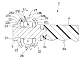
次に、図2、及び図3を用いて、操作指示装置2について、詳しく説明する。
図2に示すように、操作指示装置2は、硬質な本体部3と、この本体部3に連設される弾性部材からなるグリップ体4とから構成された略円柱形状をしており、グリップ体4の基端から信号ケーブル2aが延出している。
Next, the
As shown in FIG. 2, the
本体部3の側周面には、処置具50を操作する操作命令が入力される入力部である操作指示部5が配設されている。この操作指示部5は、いわゆるジョイスティックタイプの2軸操作自在の原点復帰型スイッチである操作レバー5aと、この操作レバー5aを支持する操作レバー支持部5bからなる。また、本体部3は、基端面中央から突起する嵌合突起部3aを有し、この嵌合突起部3aがグリップ体4の先端面に穿設される嵌合穴に嵌入することで、グリップ体4と嵌着している。
グリップ体4には、本体部3の操作指示部5と反対側となる側面に凹凸形状に形成されたグリップ部4aが形成されている。これにより、術者は、操作指示装置2を握持しやすい構成となっている。
An
The
尚、このように構成された操作指示装置2についての以下の説明において、本体部3側を先端、グリップ体4側を基端とし、本体部3に配設される操作指示部5側を上部、グリップ体4のグリップ部4a側を下部とする。
In the following description of the
図4、及び図5に示すように、操作指示部5の操作レバー支持部5bの上面には、後述するように、処置具50の操作を指示する操作レバー5aを傾倒する方向を示す指標が設けられている。
As shown in FIGS. 4 and 5, on the upper surface of the operation
その一例として、例えば、図4では、操作レバー支持部5bの先端(前方)側に指標「進」、基端(後方)側に指標「退」、先端に向かって上部方向から見た左側(図面では下部側)に指標「開」、及び先端に向かって上部方向から見た右側(図面では上部側)に指標「閉」が印字されている。また、例えば、図5では、操作レバー支持部5bの先端(前方)側、及び基端(後方)側を結ぶ方向の指標「進−退」、左側(図面では下部側)、及び右側図面では上部側)を結んだ方向の指標「左湾曲−右湾曲」が印字されている。尚、これらの指標は、使用する処置具50の種類により、種々の変更が可能である。
As an example, for example, in FIG. 4, the index “advance” is on the distal end (front) side of the operation
尚、本実施の形態の操作指示装置2は、信号ケーブル2aを介して制御装置20と接続される有線タイプであるが、図6に示すような、ワイヤレスタイプにしても良い。
詳しくは、変形例となる本実施の形態の操作指示装置2には、本体部3の内部に送信機6が内蔵され、グリップ体4の内部に電力供給用のバッテリ7が設けられている。従って、この操作指示装置2は、バッテリ7からの電力により、操作指示部5による操作指示信号を送信機6により、制御装置20へ送信する。尚、制御装置20には、送信機6からの操作指示信号を受信する受信機が設けられる。
The
Specifically, the
次に、図7、及び図8を用いて、処置具電動進退装置40について詳しく説明する。
図7に示すように、処置具電動進退装置40は、箱体41の内部に2つのローラ43a,43bが回動自在に設けられている。この箱体41には、一面に処置具50のシース52が挿入される処置具挿入部42と、該一面と反対側に前記シース52を内視鏡10の処置具チャンネルへと導き、内視鏡10の処置具挿通部12dに接続するスコープ固定部41aと、が設けられている。
Next, the treatment instrument electric advance /
As shown in FIG. 7, the treatment instrument electric advance /
処置具挿入部42は、シース52が挿入される貫通孔部に弾性部材からなる鉗子栓42aが設けられている。また、スコープ固定部41aは、内視鏡10の処置具挿通部12dのチャンネル開口部と気密に接続されている。従って、処置具電動進退装置40は、体腔内を観察し易いように内視鏡10による送気、或いは送水を行い膨張させた状態でも、処置具50のシース52を挿抜しても、体腔内の圧力が低下しないように、鉗子栓42aとスコープ固定部41aによって処置具チャンネルを気密保持する構成となっている。
The treatment
箱体41内に設けられた2つのローラ43a,43bは、弾性部材などからなり、夫々の回転軸43A,43B回りに回動自在であり、処置具50のシース52の外面を各ローラ面で押圧回動することで、シース52を処置具チャンネル内に進退移動させる。
The two
ローラ43aは、駆動側ローラであって、箱体41内に配設されたモータ44によって、回動軸43Aが駆動される。一方、ローラ43bは、受動側ローラであって、駆動側ローラ43aの回動を受けて進退されるシース52をその回動によって円滑に進退移動するためのものである。
The
尚、各ローラ43a,43bは、夫々のローラ面が所定に離間するように、且つ夫々の回動軸43A,43Bが平行となるように、箱体41の側壁と、支持板体41bによって、回動支持されている。
Each of the
次に、図9、及び図10を用いて、処置具電動開閉装置30について、詳しく説明する。
図9、及び図10に示すように、処置具電動開閉装置30は、板状のベース体31と、このベース体31の一面に突設されたリング押さえ部32と、処置具50のスライダ55を挟持するスライダ押さえ部33と、このスライダ押さえ部33と連結されるラック35と、ラック35の直線歯形35aと噛み合うピニオンギア36aがモータ軸に取り付けられたモータ36と、固定部材37a,37bによりベース体31に固定され、モータ36のピニオンギア36aを収容すると共に、ラック35を進退自在に直進保持する保持ボックス37と、ベース体31の前記一面に配され、処置具50のハンドル部53が載置される載置部38と、を有して構成される。
Next, the treatment instrument
As shown in FIGS. 9 and 10, the treatment instrument electric opening /
リング押さえ部32は、ベース体31側の端部に円環状のリング台32aが嵌着されており、このリング台32aから突出する部分が処置具50の指掛けリング54内に挿通して,ハンドル部53を処置具電動開閉装置30に固定する。このリング押さえ部32は、指掛けリング54の内径に略等しい外径が設定され、処置具50のハンドル部53を確実に保持している。尚、リング押さえ部32の外径を指掛けリング54の内径よりも若干小さく設定し、外周に弾力性のあるチューブを被せて、処置具50のハンドル部53を確実に保持するようにしても良い。
An
また、リング台32aは、ベース体31と反対側の端面が指掛けリング54に当接することで、処置具50のハンドル部53をベース体31から所定の間隔で離間させるための部材である。
The
スライダ押さえ部33は、図10の紙面に向かって見た下方、即ち、ベース体31側へ延設された2枚の保持板33aによって、スライダ55を挟持する。この処置具50のスライダ55は、両端にフランジを有するドラム形状をしている。従って、2枚の保持板33aは、スライダ55のフランジ間の胴部を挟むように保持している。このスライダ押さえ部33は、上述したように、ラック35の一端部分と止ネジ34によって連結されている。
The
ラック35は、直線歯形35aと噛合するモータ36のピニオンギア36aが回転することにより、スライダ押さえ部33と共に、保持ボックス37に相対して進退移動する。これにより、スライダ押さえ部33は、保持する処置具50のスライダ55をハンドル部53の軸に沿って進退移動する。
The
尚、処置具50には、先端の処置部51に一端が連結され、他端がスライダ55と連結された図示しない操作ワイヤがシース52内に挿通している。この操作ワイヤは、スライダ55の進退移動に伴って、牽引弛緩され、処置部51の所定操作、ここでは生検鉗子であるため、組織採取部を開閉する。
Note that an operation wire (not shown) having one end connected to the
以上のように構成された内視鏡システム1を使用して、術者は、内視鏡画像を見ながら体腔内を検査し、例えば、病変部位を発見した場合、その病変部位の切除などの治療を行う。以下に、内視鏡システム1の操作一例について、説明するが、本実施の形態では、先ず、生検鉗子を使用した場合を挙げて説明する。
Using the
先ず、術者は、上述のように、処置具電動開閉装置30に処置具50のハンドル部53を固定する(図10参照)。詳しくは、術者は、ラック35が外されているスライダ押さえ部33を処置具50のスライダ55に装着し、ハンドル部53の指掛けリング54にリング押さえ部32を挿入する。
First, as described above, the operator fixes the
このとき、術者は、処置具50のハンドル部53の一部分がベース体31に配された載置部38と当接するまで、指掛けリング54にリング押さえ部32を挿入する。そして、図10に示したように、術者は、スライダ押さえ部33とラック35を止ネジ34によって連結させる。
At this time, the surgeon inserts the
次に、術者は、内視鏡10の処置具挿通部12dに処置具電動進退装置40を装着し、処置具電動進退装置40を介して、内視鏡10の処置具チャンネル内へ処置具50の処置部51側からシース52を挿入する。このとき、術者は、処置具50の処置部51が処置具電動進退装置40内の2つのローラ43a,43bを通過して、シース52が2つのローラ43a,43b間で押圧された状態となるまで挿入する。尚、術者は、予め処置具50の処置部51が内視鏡10の挿入部11の先端部分に位置するまで、手動で処置具50のシース52を内視鏡10の処置具チャンネル内に送り込んでも良い。
Next, the surgeon attaches the treatment instrument electric advance /
そして、術者は、被検体の体腔内へ挿入部11を先端部11a側から内視鏡画像を観察しながら挿入する。例えば、術者は、内視鏡10の視野範囲内に処置する体腔内の組織が映し出されるように、挿入部11の先端部11aを前記組織の近傍に位置するように、挿入操作、及び湾曲部11bの湾曲操作を行う。そして、術者は、内視鏡画像を見ながら、体腔内の組織の処置を行う。
Then, the surgeon inserts the
詳述すると、術者は、一方の手によって、図2に示したように、操作指示装置2を保持する。そして、術者は、図11に示すように、処置具50の処置部51が組織57の近傍に達している状態から、図12に示すように、操作指示装置2の操作レバー5aを指標「進」と指標「閉」との間の領域に傾倒することで、前記処置部51を組織57に向かって前進させると共に、閉じる、つまり組織を採取する操作が行える。換言すると、図12に示すように、指標「進」と指標「閉」との間の領域に操作指示部5の操作レバー5aが傾倒操作されると、体腔内の組織57に向かって、処置具50の処置部51が導出すると共に、処置部51が閉じて、組織57を採取する。
Specifically, as shown in FIG. 2, the surgeon holds the
つまり、操作指示部5の操作レバー5aを所定の方向に傾倒操作することで、処置具50の処置部51の開閉操作、及びシース52の進退操作を行うことができる。
詳しくは、本実施の形態では、操作指示部5の操作レバー支持部5bの上面に上述の図4に示した指標「進退開閉」が配されており、術者は、例えば、操作指示部5の先端方向(図11、及び図12中の操作レバー支持部5bの指標「進」の方向)に操作レバー5aを傾倒操作すると、処置具50のシース52を前進操作することができる。その逆で、術者は、操作指示部5の基端方向(図11、及び図12中の操作レバー支持部5bの指標「退」の方向)に操作レバー5aを傾倒操作すると、処置具50のシース52を後退操作することができる。
That is, by operating the
Specifically, in the present embodiment, the indicator “advanced / retracted opening / closing” shown in FIG. 4 is arranged on the upper surface of the
また、術者は、操作指示装置2の軸方向に直交する先端に向かって見た方向の左側(図11、及び図12では、下方側となる指標「開」の方向)に操作レバー5aを傾倒操作すると、処置具50の処置部51の開操作が行え、上記左側と反対となる右側(図11、及び図12では、上方側となる指標「閉」の方向)に操作レバー5aを傾倒操作すると、処置具50の処置部の閉操作が行える。
In addition, the operator places the
即ち、操作指示部5の操作レバー5aは、操作指示部5の前後方向(指標「進−退」方向)に傾倒操作されると、信号ケーブル2aを介して、その指示信号を制御装置20(図1参照)に供給する。その指示信号を受けた制御装置20は、処置具電動進退装置40に電気ケーブル40aを介して、電力を供給すると共に、処置具電動進退装置40内のモータ44(図8参照)を所定の方向に回動させる。そして、モータ44により回動される処置具電動進退装置40内の駆動側ローラ43aの回動方向に伴って、2つのローラ43a,43b間で挿通保持されている処置具50のシース52が内視鏡10の処置具チャンネル内で進退移動する。
That is, when the
その結果、術者は、操作指示部5の操作レバー5aの前後方向の傾倒操作によって、処置具50の処置部51を内視鏡10の挿入部11の先端部11aから導出入することができる。
As a result, the surgeon can lead out the
また、操作指示部5の操作レバー5aは、操作指示部5の左右方向(指標「開−閉」方向)に傾倒操作されると、信号ケーブル45aを介して、その指示信号を制御装置20に供給する。その指示信号を受けた制御装置20は、図9、及び図10に示した処置具電動開閉装置30に電気ケーブル30aを介して、電力を供給すると共に、処置具電動開閉装置30のモータ36を所定の方向に回動させる。
Further, when the
そして、モータ36により回動されるピニオンギア36aの回動方向に伴って噛合する直線歯形35aによりラック35が保持ボックス37に対して、前後に直進移動を行う。従って、ラック35に連結されたスライダ押さえ部33は、保持している処置具50のスライダ55をハンドル部53の軸に沿って前後に移動し、処置具50の操作ワイヤを牽引弛緩する。
Then, the
その結果、術者は、操作指示部5の操作レバー5aの左右方向の傾倒操作によって、処置具50の処置部51を開閉操作することができる。
As a result, the surgeon can open and close the
尚、術者は、例えば、図12に示したように、操作指示部5の前後方向(指標「進−退」方向)と左右方向(指標「開−閉」方向)によって4つに区切られた領域に操作レバー5aを傾倒操作することで、内視鏡10の挿入部11の先端部11aから導出入操作と、処置具50の処置部51を開閉操作とを操作させる種々のパターン操作を同時に行うことができる。
For example, as shown in FIG. 12, the operator is divided into four parts by the front-rear direction (index “advance-retreat” direction) and the left-right direction (index “open-close” direction) of the
また、操作指示部5の操作レバー5aが操作される傾倒角度によって、処置具50のシース52の進退速度、及び処置具50の処置部51の開閉速度を変更することができる。つまり、操作レバー5aが傾倒する角度(初期位置に対して操作された角度)の大きさに伴って、上記各速度が速くなる。
Further, the advance / retreat speed of the
尚、上述のように、内視鏡システム1に併用される処置具50は、生検鉗子に限ることなく、例えば、以下に説明する高周波スネア、造影チューブ、バスケット把持鉗子などの各種内視鏡用医療器具でも適用可能である。
As described above, the
特に、本実施の形態の内視鏡システム1は、処置具50のシース52を前進させながら、処置部51を操作する手技の操作性を格段に向上させることができる。
その手技の一例を処置具50である高周波スネア、造影チューブ、及びバスケット把持鉗子の順で、以下に説明する。
例えば、図13、及び図14に示すように、処置具50として高周波スネアを使用した場合、術者は、図13に示す組織57の例えば処置するポリープなどの病変部位57aなどが内視鏡画像上で確認されると、図14に示すように、処置具50のシースを前進させ、組織に押し付けながら、処置部51aであるループ状のワイヤを病変部位57aに引っ掛けると共に、処置部51aをシース52内へ収容する。
In particular, the
An example of the procedure will be described below in the order of the high-frequency snare that is the
For example, as shown in FIGS. 13 and 14, when a high-frequency snare is used as the
尚、この処置具50である高周波スネアは、上述のハンドル部53が基端に設けられ、スライダ55をハンドル部53の軸に沿ってスライドすることで、処置部51aがシース52に収容されたり、シース52の先端から導出したりする構成となっている。従って、この高周波スネアもハンドル部53が処置具電動開閉装置30にセットされ、操作指示装置2の操作のもとで、処置部51aの操作がなされる。
In the high-frequency snare that is the
尚、本実施の形態に使用される高周波スネアである処置具50は、後述する第4の実施形態にて詳述するが、処置部51aに高周波電流が供給されることによって、生体組織を切開したり、止血凝固させたりすることができる。この処置具50のスライダ55には、図示しない高周波配線コードが延設され、この高周波配線コードが図示しない高周波電源装置に接続されている。高周波配線コードは、スライダ55を介して、シース52内の図示しない金属性の操作ワイヤに接続されており、処置部51aと電気的に接続されている。
Note that the
術者は、操作指示装置2の操作レバー5aを図13に示すニュートラルの状態から、図14に示す指標「進」と指標「閉」との間にある領域に傾倒操作すると、処置具50のシース52が前進すると共に、処置部51aがシース52内に収容する。これにより、術者は、処置部51aのループ状のワイヤを病変部位57aへ引っ掛けたまま、縮小させ易くなり、病変部位57aの切除などを確実に行うことができる。
When the operator tilts the
さらに、詳述すれば、例えば、図15に示すように、処置具50の処置部51aが体腔内の組織57にある病変部位57aに引っ掛けられた状態から、処置部51aのループを縮小するために、操作指示装置2の操作レバー5aを指標「閉」に傾倒すると、シース52の位置が変更されないまま、処置具51aがシース52内に収容されてしまう。
More specifically, for example, as shown in FIG. 15, in order to reduce the loop of the treatment portion 51 a from the state where the treatment portion 51 a of the
これでは、処置具50の処置部51が病変部位57aから外れてしまい、病変部位57aの処置が行えない。即ち、図15に示すように、処置具50の処置部51aの先端は、シース52の位置が変化しないため、病変部位57aに引っ掛けられた状態で破線Aの位置にあり、操作指示装置2の操作レバー5aを指標「閉」に傾倒されて、処置部51aがシース52内に収容されるにつれて、処置部51aの先端が破線B、及び破線Cの位置へと変化する。そのため、病変部位57aに引っ掛かっていた処置部51aのループが縮小するにつれて、病変部位57aから外れてしまう。
In this case, the
尚、ここでは、本実施の形態の内視鏡システム1での操作指示装置2を使った処置具50の操作を例に挙げているが、従来のように、術者自身の手による処置具50の操作では、処置部51aを操作しながらのシース52の進退操作できず、医療スタッフとの共同作業となるが、意思疎通が困難であった。
Here, although the operation of the
しかし、本実施の形態の内視鏡システム1では、図16に示すように、操作指示装置2の操作レバー5aがニュートラルの状態から、指標「進」と指標「閉」との間にある領域に傾倒操作させれば、シース52を前進させながら処置部51aのループを縮小させる(処置部51aをシース52内に収容する)ことができるため、処置部51aの先端が破線Aの位置から変化することが無い。そのため、処置部51aが病変部位57aに引っ掛かったまま縮小するため、術者は、病変部位57aを切開などの処置を容易に行える。
However, in the
つまり、上述したように、本実施の形態の内視鏡システム1は、処置具50の所望の操作を行うため、操作指示部5の前後方向と左右方向によって4つに区切られた領域に操作レバー5aを傾倒操作することで、処置具50の種々のパターン操作を容易に行うことができる。
That is, as described above, the
また、本実施の形態の内視鏡システム1の内視鏡10は、直視型内視鏡を例に挙げたが、以下に説明する、十二指腸などに使用される側視型内視鏡にでも良い。尚、説明の便宜上、側視型内視鏡の各構成については、上述の内視鏡10の各構成と同じ符号を使用して説明する。
Moreover, although the
ここでは、図17、及び図18に示すように、十二指腸59a内に内視鏡10の挿入部11を挿入し、胆管59bの結石の位置、種類、胆道の機能の異常などを発見するために、内視鏡的逆行性胆膵管造影法などを行うため、造影剤を胆管59b、膵管59cなどへ注入するための処置具である造影チューブ58を操作する一例について説明する。
Here, as shown in FIG. 17 and FIG. 18, the
尚、この造影チューブ58は、上述のハンドル部53が基端に設けられ、スライダ55をハンドル部53の軸に沿ってスライドすることで、先端部分が2方向に湾曲する構成となっている。従って、この造影チューブ58もハンドル部53が処置具電動開閉装置30にセットされ、操作指示装置2の操作のもとで、湾曲操作がなされる。従って、操作指示装置2は、図5に示した、操作レバー支持部5b上に指標「進−退」、及び指標「上湾曲−下湾曲」が印字されたタイプである。
The
図17に示すように、術者は、内視鏡(側視型)10の先端部11aが十二指腸59aの乳頭部59dの近傍に位置させ、操作指示装置2の操作レバー5aを指標「進」方向へ傾倒操作して、先端部11aの一側部から導出する造影チューブ58を乳頭部59d内へ挿入する。
As shown in FIG. 17, the operator positions the
そして、ここでは、膵管59cよりも上部側に分岐する胆管59b内へ造影チューブ58を挿入するため、操作指示装置2の操作レバー5aを指標「進」方向に傾倒したまま、図18に示すように、指標「上湾曲」方向へ傾倒操作する。
In this case, the
すると、造影チューブ58は、乳頭部59dを通過して、胆管59b内へスムーズに挿入される。つまり、術者は、造影チューブ58の先端部分を胆管59b内へ挿入しながら、胆管59bの湾曲方向に沿った湾曲操作が行える。
Then, the
また、上述したように、本実施の形態の内視鏡システム1では、操作指示部5の操作レバー5aが操作される傾倒角度によって、ここでは造影チューブ58の進退速度、及び湾曲角度を変更することができる。つまり、操作レバー5aが傾倒する角度(初期位置に対して操作された角度)の大きさに伴って、上記速度や上記湾曲角度の調整が行えるので、造影チューブ58の微妙な挿入操作が容易に行うことができる。
Further, as described above, in the
さらに、造影チューブ58により造影剤が胆管59b内へ注入され、内視鏡的逆行性胆膵管造影法などによる検査結果で、図19、及び図20に示すように、胆管59b内に結石59Aが発見された場合、ここでは、バスケット把持鉗子である処置具50を使用して、結石59Aを胆管59bから取り除く施術方法がある。
Further, a contrast medium is injected into the bile duct 59b through the
このバスケット把持鉗子である処置具50の操作においても、図19に示すように、シース52を胆管59b内へ挿入しながら、処置部51bであるバスケットを胆管59b内で展開させる。このときに、術者は、操作指示装置2の操作レバー5aを指標「進」方向へ傾倒操作して、シース52を胆管59b内へ挿入すると共に、操作レバー5aを指標「開」方向へ傾倒操作して、胆管59b内の結石59A近傍で、シース52から処置部51bを導出させ展開させる。術者は、このシース52を胆管59b内へ挿入する操作と、シース52から処置部51bを導出させ展開させる操作は、必ずしも同時に行わなくてもよい。尚、ここでの操作指示装置2は、図4に示した、操作レバー支持部5b上に指標「進−退」、及び指標「開−閉」が印字されたタイプである。
Also in the operation of the
その後、術者は、図20に示すように、操作指示装置2の操作レバー5aを指標「退」と指標「閉」の間の領域、及び指標「退」と指標「開」の間の領域へ交互に傾倒操作する。つまり、処置部51bを開閉させることで、ワイヤ同士の間隔を大きくしたり小さくしたり、また結石59Aに対して、ワイヤの接触する向きを変えたりすることができるので、結石59Aを処置部51bであるバスケット内に容易に収容することができる。そして、結石59Aが処置部51b(バスケット)内に収容されたら、術者は、操作指示装置2の操作レバー5aを指標「退」と指標「閉」の間の領域に傾倒操作することで、処置部51b(バスケット)が収縮した状態となり、確りと結石59Aを処置部51b(バスケット)内で保持したまま、胆管59bから取り出すことができる。
Thereafter, as shown in FIG. 20, the surgeon moves the
ここでも、本実施の形態の内視鏡システム1は、結石59Aなどの体腔内の異物除去のため処置具50であるバスケット把持鉗子の処置部51b(バスケット)をシース52から導出入させて展開、或いは収縮させる微妙な操作を容易に行うことができる。
Also in this embodiment, the
以上に説明したように、本実施の形態の内視鏡システム1によれば、各種内視鏡10と併用される処置具50(造影チューブ58)の操作は、ハンドル部53を握持することなく、術者自身が手元の操作指示装置2で行える構成となっている。そのため、処置具50(造影チューブ58)の微妙な操作時、術者自ら的確な処置具の操作が行える。
As described above, according to the
以上の結果、本実施の形態の内視鏡システム1は、内視鏡10と併用される各種医療用器具である処置具50(造影チューブ58)を容易に操作することができる。
As a result, the
(第2の実施の形態)
次に、図21〜図24を用いて、本発明の第2の実施の形態について説明する。尚、図21〜図24は、本発明の第2の実施の形態に係り、図21は内視鏡システムを示す全体構成図、図22は処置具電動開閉装置を側方から見た平面図、図23、及び図24は操作指示装置による処置具(バスケット把持鉗子)の操作一例を説明するための図である。
(Second Embodiment)
Next, a second embodiment of the present invention will be described with reference to FIGS. 21 to 24 relate to the second embodiment of the present invention, FIG. 21 is an overall configuration diagram showing the endoscope system, and FIG. 22 is a plan view of the treatment instrument electric switchgear as viewed from the side. 23 and 24 are diagrams for explaining an example of operation of the treatment instrument (basket gripping forceps) by the operation instruction device.
また、本実施の形態の内視鏡システムの説明において、第1の実施の形態に記載した各構成と同じ構成については、同じ符号を使用して、それらの詳細な説明を省略する。尚、本実施の形態においての処置具50は、バスケット把持鉗子を例に挙げて説明するが、これに限ることなく、例えば、生検鉗子、高周波スネアなどの医療用器具にも適用可能である。さらに、本実施の形態の内視鏡10は、上述した側視型内視鏡である。
In the description of the endoscope system according to the present embodiment, the same components as those described in the first embodiment are denoted by the same reference numerals, and detailed description thereof is omitted. The
図21に示す、本実施の形態の内視鏡システム1は、処置部51がシース52と共に、シース52の長軸回りに回動自在な生検鉗子などの医療器具である処置具50に対応する構成となっている。詳述すると、内視鏡用操作補助装置の構成の1つである処置具電動開閉装置30には、処置具50のハンドル部53の先端部分からシース52、及び処置部51をシース52の長軸回りに回動させるための回動モータ38が設けられている。
The
この回動モータ38は、モータ軸の端部に平歯車である回転伝達ギヤ(以下、単にギヤという)39を有し、制御装置20と電気ケーブル38aによって電気的に接続されている。この回動モータ38は、図22に示すように、処置具電動開閉装置30の略ハット形状に形成されたベース体31aの背面側に固設されている。
The
また、ベース体31aには、処置具50が配される側の面から回動モータ38のギヤ39が露呈できるように孔部31cが形成されている。更に、このベース体31には、処置具50のハンドル部53の先端部分を回動保持する保持部31bが設けられている。
Further, a
処置具50のハンドル部53の先端部分には、ベース体31aの孔部31cから露呈したギヤ39と噛合する受動ギヤ(以下、単にギヤという)53aが設けられている。
A passive gear (hereinafter simply referred to as a gear) 53 a that meshes with the
本実施の形態の操作指示装置2には、図23、及び図24に示すように、操作指示部5が設けられた反対側の外周部に入力部である回動指示部8が設けられている。つまり、操作指示装置2には、その本体部3を挟むように、操作指示部5と回動指示部8とが異なる方向に突出するように設けられている。詳述すると、操作指示部5と回動指示部8は、夫々が突出する方向が逆の方向を向くように、本体部3の外周部に配設されている。
As shown in FIGS. 23 and 24, the
この回動指示部8は、グリップ体4から延出する制御装置20と接続される信号ケーブル2aと電気的に接続されている。また、回動指示部8は、操作指示装置2の軸方向に直交する方向へと回動操作される回動操作レバー8aと、この回動操作レバー8aを回動保持する操作レバー支持部8bとにより構成されている。
The
回動指示部8は、図23に示すように、回動操作レバー8aを操作指示装置2の軸に沿った前後方向に傾倒するように、操作レバー支持部8bに対して回動操作することで、処置具50のシース52を処置部51b(バスケット)と共に、回動する。本実施の形態においては、例えば、回動操作レバー8aを前方に傾倒すると、基端から先端に向かった反時計回りである右回転でシース52を処置部51b(バスケット)と共に回転させることができ、回動操作レバー8aを後方に傾倒すると、基端から先端に向かった時計回りである左回転でシース52を処置部51b(バスケット)と共に回転させることができる設定となっている。
As shown in FIG. 23, the
すなわち、術者は、第1の実施の形態で記載したように、親指などで操作指示部5を操作することで、処置具50aのシース52を進退移動させたり、処置部51b(バスケット)を展開、或いは収縮させたりできると共に、人差し指などによって、回動指示部8を操作することで、処置部51b(バスケット)をシース52の軸回りに回動操作できる。
That is, as described in the first embodiment, the operator operates the
詳述すると、回動指示部8の回動操作レバー8aを前後どちらかに傾倒すると、その指示信号が信号ケーブル2aを介して制御装置20に供給される。そして、この指示信号を受けた制御装置20は、電気ケーブル38aを介して、回動モータ38に所定の回転方向の電力を供給する。この電力を受けた回動モータ38は、ギヤ39を所定方向に回転させて、このギヤ39と噛合するギヤ53aを介して、内視鏡10の処置具チャンネルに挿通する処置具50aのシース52を軸回りに回転させる。尚、ギヤ39が回転する所定の方向は、ギヤ53aが回転する方向と逆となるため、モータ38aの回転方向は、シース52を回転させる方向と逆方向となる。
More specifically, when the rotation operation lever 8a of the
そして、シース52の回転力は、先端に配された処置部51に伝達され、処置部51が所定の方向、ここでは、回動操作レバー8aが前方に傾倒された場合、基端から先端に向かった右回りの方向に回動し、回動操作レバー8aが後方に傾倒された場合、基端から先端に向かった左回りの方向に回動する。尚、回動操作レバー8aの傾倒操作方向に対するシース52、及び処置部51b(バスケット)の回動方向を上述の方向と逆方向に設定しても良い。
Then, the rotational force of the
また、本実施の形態においても、回動指示部8の回動操作レバー8aが操作される傾倒角度によって、処置具50のシース52、及び処置部51b(バスケット)の回転速度を変更することができる。つまり、回動操作レバー8aが傾倒する角度(初期位置に対して操作された角度)の大きさに伴って、上記回転速度が速くなる。
Also in the present embodiment, the rotation speed of the
以上のように構成された本実施の形態の内視鏡システム1は、図23にしめすように、第1の実施の形態と同様にして、十二指腸59aに挿入された内視鏡10の挿入部11の先端部11aからシース52を導出され、胆管59b内に挿入すると共に、処置部51bを展開される。
As shown in FIG. 23, the
そして、術者は、図24に示すように、操作指示部5の操作レバー5aを操作指示装置2の後方側へ傾倒し、シース52を内視鏡10の処置具チャンネル内に導入しながら、回動指示部8の回動操作レバー8aを操作指示装置2の前方側へ傾倒操作して、処置部51b(バスケット)を回転(ここでは右回転)させ、胆管59b内の結石59Aを処置部51b内に収容する。また、これと同時に、術者は、操作指示部5の操作レバー5aを操作指示装置2の指標「閉」方向へ傾倒操作して、処置部51b(バスケット)が収縮させて、結石59Aを処置部51b(バスケット)内で保持したまま、胆管59bから取り出すことができる。
Then, as shown in FIG. 24, the surgeon tilts the
以上のように構成された本実施の形態の内視鏡システム1は、第1の実施の形態の効果を奏すると共に、シース52の軸回りに回動可能な処置具50に対応した構成とすることができる。また、操作指示装置2に操作指示部5が設けられる反対側の外周部に回動指示部8を設けることで、各指示部5,8の夫々の操作を同時に行い易い構成となっている。
The
つまり、術者は、処置具50の3つの操作であるシース52の進退操作、処置部51bの開閉操作(ここでは、バスケットの展開、及び収縮)、及び処置部51bの回転操作を操作指示装置2によって、手元で同時に行うことができる。
That is, the surgeon operates the operation instruction device with three operations of the
(第3の実施の形態)
次に、図25〜図27を用いて、本発明の第3の実施の形態について説明する。尚、図25〜図27は、本発明の第3の実施の形態に係り、図25は内視鏡システムを示す全体構成図、図26、及び図27は操作指示装置による処置具(バルーンカテーテル)の操作一例を説明するための図である。また、本実施の形態の内視鏡システムの説明においても、第1の実施の形態に記載した各構成と同じ構成については、同じ符号を使用して、それらの詳細な説明を省略する。
(Third embodiment)
Next, a third embodiment of the present invention will be described with reference to FIGS. FIGS. 25 to 27 relate to a third embodiment of the present invention, FIG. 25 is an overall configuration diagram showing an endoscope system, and FIGS. 26 and 27 are treatment tools (balloon catheters) by an operation instruction device. It is a figure for demonstrating an example of operation of (). In the description of the endoscope system according to the present embodiment, the same reference numerals are used for the same components as those described in the first embodiment, and the detailed description thereof is omitted.
尚、本実施の形態においての処置具は、上述のバスケット把持鉗子では回収困難な微細な結石の回収が行えるバルーンカテーテルを例に挙げて説明する。さらに、本実施の形態の内視鏡10は、側視型内視鏡である。
The treatment instrument in the present embodiment will be described by taking a balloon catheter that can collect a fine calculus that is difficult to collect with the basket grasping forceps described above as an example. Furthermore, the
図25に示すように、本実施の形態の内視鏡システム1に使用される処置具50bは、基端部にシリンジ53aが設けられ、シース52の先端部分に処置部51cである弾性部材からなるバルーンを有している。この処置具50bは、シリンジ53a内のエアーなどの流体がピストン部53bの移動により、シース52を介して処置部(バルーン)51cに注入されて、この処置部(バルーン)51cが膨張する。
As shown in FIG. 25, the treatment instrument 50b used in the
そのため、内視鏡システム1は、シリンジ53aのピストン部53bをシリンジ53aに対して進退させるために、処置具電動開閉装置30のスライダ押さえ部33がピストン部53bの基端にあるフランジに固定されている。また、処置具電動開閉装置30のベース体31には、処置具50bのシリンジ53aの胴部を保持固定する固定部31dが設けられている。
Therefore, in the
そのため、処置具電動開閉装置30は、上述の各実施の形態と同じように、操作指示装置2の操作レバー5aの指標「進−退」方向への傾倒操作に伴って、ラック35が進退移動し、ピストン部53bをシリンジ53aに対して内部で進退させる。
Therefore, in the treatment instrument electric opening /
このように構成された、本実施の形態の内視鏡システム1は、十二指腸59aまで内視鏡10の挿入部11が挿入され、先端部11aの側部から処置具50bのシース52が胆管59b内に挿入される。そして、図26に示すように、術者は、操作指示装置2の操作レバー5aが指標「開」方向へ傾倒操作すると、処置部(バルーン)51cがシリンジ53aからのエアーなどの流体が注入されて、胆管59b内で膨張する。
In the
そして、術者は、図27に示すように、操作指示装置2の操作レバー5aが指標「退」と指標「閉」との間の領域へ傾倒操作し、シース52を内視鏡10の処置具チャンネル内へ導入しながら、処置部(バルーン)51cを収縮させる。このようにして、術者は、回収困難な微細な結石59Aの回収を行う。
Then, as shown in FIG. 27, the surgeon tilts the
以上のように構成された、本実施の形態の内視鏡システム1は、上述の各実施の形態とは異なるシリンジ53aを備えたバルーンカテーテルなどの処置具50bにも容易に適用可能である。そのため、内視鏡システム1は、上述の各実施の形態の効果と同じように、内視鏡10と併用される各種医療用器具である処置具50b(ここでは、シリンジ53aを備えたバルーンカテーテル)を容易に操作することができる。
The
(第4の実施の形態)
次に、図28を用いて、本発明の第4の実施の形態について説明する。尚、図28は、本発明の第4の実施の形態に係る、本実施の形態の内視鏡システムを示す全体構成図である。また、本実施の形態の内視鏡システムの説明においても、第1の実施の形態に記載した各構成と同じ構成については、同じ符号を使用して、それらの詳細な説明を省略する。
(Fourth embodiment)
Next, a fourth embodiment of the present invention will be described with reference to FIG. FIG. 28 is an overall configuration diagram showing an endoscope system according to the present embodiment according to the fourth embodiment of the present invention. In the description of the endoscope system according to the present embodiment, the same reference numerals are used for the same components as those described in the first embodiment, and the detailed description thereof is omitted.
図28に示すように、本実施の形態の内視鏡システム1は、内視鏡10と、制御装置20と、内視鏡用操作補助装置である操作指示装置2と、によって構成されている。尚、この内視鏡システム1は、高周波スネア、ホットバイオプシ鉗子、電気メスなどの体腔内の病変部を高周波によって治療する医療器具である処置具50の操作を行うためのものである。尚、本実施の形態においての処置具50は、高周波スネアを例に挙げて説明する。
As shown in FIG. 28, the
本実施の形態に使用される高周波スネアである処置具50は、第1の実施の形態と同じ構成をしており、処置部51aに高周波電流が供給されることによって、生体組織を切開したり、止血凝固させたりすることができる。
The
この処置具50のスライダ55には、高周波配線コード21aが延設され、この高周波配線コード21aが高周波電源装置21に接続されている。高周波配線コード21aは、スライダ55を介して、シース52内の図示しない金属性の操作ワイヤに接続されており、処置部51aと電気的に接続されている。
A high frequency wiring cord 21 a extends from the
高周波電源装置21は、高周波配線コード21aを介して、高周波を処置部51aに供給する。この高周波電源装置21は、通信ケーブル20aを介して、制御装置20に接続されている。
The high frequency
操作指示装置2には、上述の各実施の形態と同様に、本体部3の上部側の外周部に入力部である操作指示部5は配設され、この操作指示部5の反対側の本体部3の上部側の外周部に別の入力部となる高周波出力スイッチ9が設けられている。尚、この高周波出力スイッチ9は、生体組織を凝固するに最適な高周波を供給する凝固スイッチ、生体組織を切開するに最適な高周波を供給する切開スイッチ、及び高周波の出力を調整するダイヤルなど有していても良い。
In the
即ち、本実施の形態の内視鏡システム1は、上述の各実施の形態と同様にして、処置具50の操作を操作指示装置2の操作指示部5により行えると共に、高周波電源装置21から処置具50への高周波の供給を高周波出力スイッチ9によって行える構成となっている。
That is, the
その結果、本実施の形態の内視鏡システム1は、上述の各実施の形態の効果を奏すると共に、例えば、高周波スネアなどの高周波を使用する処置具50にも適用できる構成となっている。操作指示装置2により操作される処置具50は、高周波スネアに限ることなく、勿論、ホットバイオプシ鉗子、電気メスなどにも適用可能である。また、高周波スネアなどの処置具50への高周波の出力は、操作指示装置2の操作指示部5の操作と同時に行うことができる。
As a result, the
(第5の実施の形態)
次に、図29〜図40を用いて、本発明の第5の実施の形態について説明する。尚、本実施の形態では、上述した各実施の形態の操作指示装置の種々の変形例について説明する。また、本実施の形態の内視鏡システムの説明においても、第1の実施の形態に記載した各構成と同じ構成については、同じ符号を使用して、それらの詳細な説明を省略する。
(Fifth embodiment)
Next, a fifth embodiment of the present invention will be described with reference to FIGS. In the present embodiment, various modifications of the operation instruction device according to each of the above-described embodiments will be described. In the description of the endoscope system according to the present embodiment, the same reference numerals are used for the same components as those described in the first embodiment, and the detailed description thereof is omitted.
図29〜図40は、本発明の第4の実施の形態に係り、図29は第1変形例の操作指示装置の全体構成図、図30は図29の操作指示装置の断面図、図31は図29の操作指示装置が術者などにより握持された状態を示す図、図32は第2変形例の操作指示装置の全体構成図、図33は図32の操作指示装置の断面図、図34、及び図35は図32の操作指示装置の作用を説明する断面図、図36は第3変形例の操作指示装置の全体構成図、図37は図36の操作指示装置が術者などにより握持された状態を示す図、図38は第4変形例の操作指示装置の全体構成図、図39は図38の操作指示装置の側面図、図40は図38の操作指示装置が術者などにより握持された状態を示す図である。 FIGS. 29 to 40 relate to the fourth embodiment of the present invention, FIG. 29 is an overall configuration diagram of the operation instruction device of the first modification, FIG. 30 is a cross-sectional view of the operation instruction device of FIG. Is a diagram showing a state in which the operation instruction device of FIG. 29 is gripped by an operator, etc., FIG. 32 is an overall configuration diagram of the operation instruction device of the second modification, FIG. 33 is a cross-sectional view of the operation instruction device of FIG. 34 and 35 are sectional views for explaining the operation of the operation instruction device of FIG. 32, FIG. 36 is an overall configuration diagram of the operation instruction device of the third modification, and FIG. 37 is an operation instruction device of FIG. FIG. 38 is an overall configuration diagram of the operation instruction device of the fourth modified example, FIG. 39 is a side view of the operation instruction device of FIG. 38, and FIG. 40 is an operation of the operation instruction device of FIG. It is a figure which shows the state held by the person etc.
先ず、図29〜図31を用いて、本実施の形態の第1変形例となる操作指示装置2について説明する。
図29、及び図30に示す第1の変形例である操作指示装置2は、本体部3の側周部の上部側と下部側に操作指示部15,16が設けられている。
First, the
29 and 30 is an
この本体部3の側周部の上部側に配される操作指示部15は、操作指示装置2の軸に沿って前後の単軸操作される操作レバー15aと、この操作レバー15aを回動支持する操作レバー支持部15bから構成されている。この操作レバー15aは、その前後の単軸操作により、処置具50のシース52を進退移動するためのレバーである。
The
即ち、操作レバー15aは、操作指示装置2の前方側に傾倒操作されると、処置具電動進退装置40が処置具50のシース52を内視鏡10の処置具チャンネル内に導入する方向へ前進させる。その一方で、操作レバー15aは、操作指示装置2の後方側に傾倒操作されると、処置具電動進退装置40が処置具50のシース52を内視鏡10の処置具チャンネル内から導出する方向へ後退させる。
That is, when the
また、本体部3の側周部の下部側に配される入力部である操作指示部16は、操作指示装置2の軸に沿って前後の単軸操作される操作レバー16aと、この操作レバー16aを回動支持する操作レバー支持部16bから構成されている。この操作レバー16aは、その前後の単軸操作により、処置具50の処置部51を開閉(或いは、上下湾曲など)するためのレバーである。
In addition, an
即ち、操作レバー16aは、操作指示装置2の前方側に傾倒操作されると、処置具電動開閉装置30が処置具50のハンドル部53に沿ってスライダ55を所定の方向へ移動し、処置部51が開く(或いは、上湾曲する)。その一方で、操作レバー16aは、操作指示装置2の後方側に傾倒操作されると、処置具電動開閉装置30が処置具50のハンドル部53に沿ってスライダ55を所定の方向へ移動し、処置部51が閉じる(或いは、下湾曲する)。
That is, when the
尚、各操作指示部15,16は、処置具50のシース52の進退操作、或いは処置部51の開閉(湾曲)操作を逆とする、操作レバー15aによって、処置部51の開閉(湾曲)操作でき、操作レバー16aによって、シース52の進退操作ができるようにしても良い。
In addition, each operation instruction |
このように構成された操作指示装置2は、図31に示すように、術者の一方の手によって握持され、例えば、操作レバー15aが親指、操作レバー16aが人差し指などにより前後への傾倒操作がなされる。
As shown in FIG. 31, the
以上に説明したように、本実施の形態の第1変形例の操作指示装置2は、上述の各実施の形態に述べた1つの操作指示部5により、処置具50のシース52の進退操作、及び処置部51の開閉(湾曲)操作を行う構成ではなく、処置具50の各操作を個々に行う2つの操作指示部15,16を有した構成となっている。このように構成された操作指示装置2でも、上述の各実施の形態に記載した処置具50の操作性が変更することなく、同様な効果を奏する。
As described above, the
次に、図32〜図35を用いて、本実施の形態の第2変形例となる操作指示装置2について説明する。
図32、及び図33に示す第2変形例の操作指示装置2は、第1変形例と同じように、本体部3の外周部の上下に操作指示部25,28を有している。また、この操作指示装置2は、入力部である各操作指示部25,28の前後に本体部3の側周部から突起するレバー固定部であるレバーロック部22を有している。
Next, an
The
各操作指示部25,28は、夫々、操作レバー23,26と、操作レバー支持部24,27とを有している。各操作レバー23,26は、横断面が略十字状の操作軸23a,26aを有し、これら操作軸23a,26aは、中途部分から前後に円弧状に延出した突出端に沿った縁辺部に凸部23b,26bが設けられている。尚、ここでは、操作指示部25は、処置具50のシース52の進退操作を行うためのものであり、操作指示部28は処置部51の開閉(湾曲)操作を行うためのものとする。
The
各レバーロック部22は、略円弧状に本体部3の側周部から突出しており、操作レバー23,26側の面に操作指示装置2の軸に略直交する方向に沿った2つのロック溝22a,22bが形成されている。これら2つのロック溝22a,22bは、所定の間隔で平行に形成され、ロック溝22aがロック溝22bよりも、本体部3の側周面近傍に位置している。尚、これらのロック溝22a,22bは、2つに限ることなく、1つでも、3つ以上でも良い。
Each
以上のように構成された操作指示装置2は、図34、及び図35に示すように、操作レバー23、26を前後方向へ傾倒した状態で保持固定することができる。
詳しくは、図34に示すように、操作レバー23が前方へ傾倒操作され、凸部23bがロック溝22bに嵌入されると、操作軸23aが初期位置に対する第1の角度α1で傾倒したままロックされる。これにより、処置具50のシース52は、内視鏡10の処置具チャンネル内を一定の第1の速度で導入される。
As shown in FIGS. 34 and 35, the
Specifically, as shown in FIG. 34, when the
また、図35に示すように、操作レバー23が更に、前方へ傾倒操作され、凸部23bがロック溝22aに嵌入されると、操作軸23aが初期位置に対する第2の角度α2で傾倒したままロックされる。この第2の角度α2は、上述の第1の角度α1よりも大きな角度(α2>α1)であるため、処置具50のシース52は、内視鏡10の処置具チャンネル内を上記第1の速度よりも速い、一定の第2の速度で導入される。
As shown in FIG. 35, when the
同じように、操作レバー26では、その傾倒する角度(α1,α2)でロックすることによって、処置部51の開閉(湾曲)速度、及び把持力(湾曲角度)を変更することができる。
Similarly, the operating
以上説明したように、本実施の形態の第2変形例の操作指示装置2は、術者が操作指示部25,28の各操作レバー23,26を所定の角度(α1,α2)で傾倒したままロックすることができる構成となっている。そのため、術者は、所定の角度(α1,α2)で傾倒する各操作レバー23,26から操作する指を放しても、処置具50の操作を行うことができる上、シース52を一定の速度で導出入、及び処置部51の開閉(湾曲)速度、一定の把持力(湾曲角度)を保つことができる。
As described above, in the
次に、図36、及び図37を用いて、本実施の形態の第3変形例となる操作指示装置2について説明する。
図36に示すように、第3の変形例の操作指示装置2は、前面に凹凸が形成されたグリップ面17aを有するスティック体17と、このスティック体17の上部に2軸操作により処置具50の各操作を行うことができる操作指示部5と、を有している。尚、このスティック体17の下部側の後面からは、電気ケーブル2aが延出している。
Next, an
As shown in FIG. 36, the
このように構成された操作指示装置2は、図37に示すように、スティック体17が術者によって握持され、操作指示部5を例えば、親指により操作される。このような構成にしても、上述の各実施の形態と同じ効果を奏する。
In the
次に、図38〜図40を用いて、本実施の形態の第4変形例となる操作指示装置2について説明する。
図38に示すように、第4の変形例の操作指示装置2は、第3の変形例のスティック体17に単軸操作により、シース52の進退操作、或いは処置部51の開閉(湾曲)操作を夫々行う2つの操作指示部15,16を有している。
Next, with reference to FIGS. 38 to 40, the
As shown in FIG. 38, the
本変形例の操作指示装置2では、図39に示すように、スティック体17の上部にシース52の進退操作を行うための操作指示部15を配し、スティック体17の上部側前面に処置部51の開閉(湾曲)操作を行うための操作指示部16を配した構成となっている。尚、勿論、上記各操作指示部15,16による処置具50の各操作を逆とする構成にしても良い。
In the
このように構成された操作指示装置2は、図40に示すように、スティック体17が術者によって握持され、操作指示部15が例えば、親指により操作され、操作指示部16が例えば、人差し指により操作される。このような構成にしても、上述の各実施の形態と同じ効果を奏する。
As shown in FIG. 40, the
また、以上各実施の形態で説明した各操作指示部5,15,16,28,25は、単軸操作、或いは2軸操作による処置具50の各操作を行える構成としたが、3軸操作、4軸操作などにして、他の処置具50の操作、例えば、高周波の供給、凝固モード、切開モードなどの選択を行えるようにしてもよい。尚、3軸操作とは、操作レバー(5aなど)を軸に沿ってプッシュ、或いは回転するとスイッチをON/OFFさせるなどのスイッチ機能であり、4軸操作とは、操作レバー(5aなど)をプッシュ、及び回転により、2つのスイッチON/OFFさせるなどのスイッチ機能のことである。
In addition, the
また、本実施の形態では、処置具50の各操作について言及したが、これに限ることなく、内視鏡10の各種機能、例えば、湾曲操作、各種光学系機能操作、送気送水操作など、他の医療機器の各種操作などを操作指示装置2により行えるようにしても良い。
Further, in the present embodiment, reference has been made to each operation of the
以上の各実施の形態に記載した発明は、夫々の実施の形態に限ることなく、その他、実施段階ではその要旨を逸脱しない範囲で種々の変形を実施し得ることが可能である。さらに、上記各実施形態には、種々の段階の発明が含まれており、開示される複数の構成要件における適宜な組合せにより種々の発明が抽出され得る。 The invention described in each of the above embodiments is not limited to each embodiment, and various modifications can be made without departing from the scope of the invention in the implementation stage. Further, the above embodiments include inventions at various stages, and various inventions can be extracted by appropriately combining a plurality of disclosed constituent elements.
例えば、各実施形態に示される全構成要件から幾つかの構成要件が削除されても、発明が解決しようとする課題の欄で述べた課題が解決でき、発明の効果で述べられている効果が得られる場合には、この構成要件が削除された構成が発明として抽出され得る。 For example, even if some constituent elements are deleted from all the constituent elements shown in each embodiment, the problems described in the column of problems to be solved by the invention can be solved, and the effects described in the effects of the invention can be achieved. In the case of being obtained, a configuration from which this configuration requirement is deleted can be extracted as an invention.
1・・・内視鏡システム
2・・・操作指示装置
5a・・・操作レバー
5b・・・操作レバー支持部
5・・・操作指示部
10・・・内視鏡
11・・・挿入部
30・・・処置具電動開閉装置
40・・・処置具電動進退装置
50・・・処置具
51・・・処置部
52・・・シース
DESCRIPTION OF
Claims (8)
上記医療器具の操作部が装着され、該医療器具の処置部を動作させる動作装置と、
上記医療器具への第1の操作命令が入力される第1の入力部および第2の操作命令が入力される第2の入力部を有し、該第1の操作命令または該第2の操作命令に従って、上記進退装置または上記動作装置に動作指示信号を出力する操作指示装置と、
上記動作装置が有し、上記操作指示装置からの上記第2の操作命令に従って、上記医療器具の上記処置部を長軸回りに回動させる回動機構と、
を備え、
上記操作指示装置は、上記第1の入力部への上記第1の操作命令と、上記第2の入力部に上記動作装置の上記回動機構を動作させる上記第2の操作命令と、を同時に入力可能であって、これら第1、及び第2の操作命令に従って、上記進退装置、及び上記動作装置の上記回動機構に夫々の動作指示信号を同時に出力可能であることを特徴とする内視鏡用操作補助装置。 An advance / retreat apparatus for advancing / retreating a medical instrument inserted into a body cavity via an insertion portion of an endoscope;
An operation device that is mounted with the operation unit of the medical instrument and operates the treatment unit of the medical instrument;
A first input unit for inputting a first operation command to the medical instrument and a second input unit for inputting a second operation command, the first operation command or the second operation; In accordance with a command , an operation instruction device that outputs an operation instruction signal to the advance / retreat device or the operation device;
A rotating mechanism that the operating device has and rotates the treatment portion of the medical instrument around a major axis in accordance with the second operation command from the operation instruction device;
With
The operation instruction device simultaneously outputs the first operation command to the first input unit and the second operation command to cause the second input unit to operate the rotation mechanism of the operation device. An endoscope that is capable of inputting and capable of simultaneously outputting respective operation instruction signals to the advance / retreat apparatus and the rotation mechanism of the operation apparatus according to the first and second operation commands. Operation assistance device for mirrors.
Priority Applications (4)
| Application Number | Priority Date | Filing Date | Title |
|---|---|---|---|
| JP2005313457A JP4763420B2 (en) | 2005-10-27 | 2005-10-27 | Endoscope operation assistance device |
| US11/588,578 US8512227B2 (en) | 2005-10-27 | 2006-10-27 | Apparatus for assisting operations of medical instrument attached to endoscope |
| EP06022519A EP1779801B9 (en) | 2005-10-27 | 2006-10-27 | Apparatus for commanding and assisting operations of a medical endoscopic instrument |
| DE602006010954T DE602006010954D1 (en) | 2005-10-27 | 2006-10-27 | Device for controlling and supporting a medical endoscopic instrument |
Applications Claiming Priority (1)
| Application Number | Priority Date | Filing Date | Title |
|---|---|---|---|
| JP2005313457A JP4763420B2 (en) | 2005-10-27 | 2005-10-27 | Endoscope operation assistance device |
Publications (2)
| Publication Number | Publication Date |
|---|---|
| JP2007117394A JP2007117394A (en) | 2007-05-17 |
| JP4763420B2 true JP4763420B2 (en) | 2011-08-31 |
Family
ID=37685321
Family Applications (1)
| Application Number | Title | Priority Date | Filing Date |
|---|---|---|---|
| JP2005313457A Expired - Lifetime JP4763420B2 (en) | 2005-10-27 | 2005-10-27 | Endoscope operation assistance device |
Country Status (4)
| Country | Link |
|---|---|
| US (1) | US8512227B2 (en) |
| EP (1) | EP1779801B9 (en) |
| JP (1) | JP4763420B2 (en) |
| DE (1) | DE602006010954D1 (en) |
Families Citing this family (87)
| Publication number | Priority date | Publication date | Assignee | Title |
|---|---|---|---|---|
| US8414505B1 (en) | 2001-02-15 | 2013-04-09 | Hansen Medical, Inc. | Catheter driver system |
| US7618413B2 (en) * | 2005-06-22 | 2009-11-17 | Boston Scientific Scimed, Inc. | Medical device control system |
| US8715270B2 (en) * | 2006-12-01 | 2014-05-06 | Boston Scientific Scimed, Inc. | Multi-part instrument systems and methods |
| EP4233962B1 (en) | 2007-05-18 | 2025-11-05 | Boston Scientific Scimed, Inc. | Medical drive systems |
| US8105230B2 (en) | 2007-07-09 | 2012-01-31 | Olympus Medical Systems Corp. | Medical system |
| CN101449987B (en) * | 2007-11-29 | 2010-06-09 | 许尚栋 | Sacculus conveyer |
| US9161817B2 (en) | 2008-03-27 | 2015-10-20 | St. Jude Medical, Atrial Fibrillation Division, Inc. | Robotic catheter system |
| US9241768B2 (en) | 2008-03-27 | 2016-01-26 | St. Jude Medical, Atrial Fibrillation Division, Inc. | Intelligent input device controller for a robotic catheter system |
| WO2009120982A2 (en) | 2008-03-27 | 2009-10-01 | St. Jude Medical, Atrial Fibrillation Division, Inc. | Robotic catheter system with dynamic response |
| US8317744B2 (en) | 2008-03-27 | 2012-11-27 | St. Jude Medical, Atrial Fibrillation Division, Inc. | Robotic catheter manipulator assembly |
| US8684962B2 (en) | 2008-03-27 | 2014-04-01 | St. Jude Medical, Atrial Fibrillation Division, Inc. | Robotic catheter device cartridge |
| US8641663B2 (en) | 2008-03-27 | 2014-02-04 | St. Jude Medical, Atrial Fibrillation Division, Inc. | Robotic catheter system input device |
| US8343096B2 (en) | 2008-03-27 | 2013-01-01 | St. Jude Medical, Atrial Fibrillation Division, Inc. | Robotic catheter system |
| US20090281378A1 (en) * | 2008-05-09 | 2009-11-12 | Kazuo Banju | Medical system |
| US20090312645A1 (en) * | 2008-06-16 | 2009-12-17 | Boston Scientific Scimed, Inc. | Methods and Devices for Accessing Anatomic Structures |
| JP5484699B2 (en) * | 2008-09-08 | 2014-05-07 | オリンパスメディカルシステムズ株式会社 | Endoscope insertion aid and endoscope apparatus |
| WO2010055745A1 (en) * | 2008-11-14 | 2010-05-20 | オリンパスメディカルシステムズ株式会社 | Medical system |
| JP5773884B2 (en) * | 2008-12-31 | 2015-09-02 | セント・ジュード・メディカル・エイトリアル・フィブリレーション・ディヴィジョン・インコーポレーテッド | Robot catheter system input device |
| WO2011008922A2 (en) * | 2009-07-16 | 2011-01-20 | Hansen Medical, Inc. | Endoscopic robotic catheter system |
| US9330497B2 (en) | 2011-08-12 | 2016-05-03 | St. Jude Medical, Atrial Fibrillation Division, Inc. | User interface devices for electrophysiology lab diagnostic and therapeutic equipment |
| US9439736B2 (en) | 2009-07-22 | 2016-09-13 | St. Jude Medical, Atrial Fibrillation Division, Inc. | System and method for controlling a remote medical device guidance system in three-dimensions using gestures |
| EP2542296A4 (en) | 2010-03-31 | 2014-11-26 | St Jude Medical Atrial Fibrill | INTUITIVE USER INTERFACE CONTROL FOR REMOTE CATHETER NAVIGATION AND 3D CARTOGRAPHY AND VISUALIZATION SYSTEMS |
| WO2012167043A2 (en) * | 2011-06-02 | 2012-12-06 | Medrobotics Corporation | Robotic systems, robotic system user interfaces, human interface devices for controlling robotic systems and methods of controlling robotic systems |
| EP2744388B1 (en) * | 2011-08-21 | 2020-04-01 | TransEnterix Europe Sàrl | Wearable user interface |
| DE102012207707A1 (en) | 2012-05-09 | 2013-11-28 | Deutsches Zentrum für Luft- und Raumfahrt e.V. | Minimally invasive instrument for robotic surgery |
| US20130317519A1 (en) | 2012-05-25 | 2013-11-28 | Hansen Medical, Inc. | Low friction instrument driver interface for robotic systems |
| CN113397655A (en) | 2012-11-14 | 2021-09-17 | 直观外科手术操作公司 | System and method for dual control surgical instrument |
| US9668814B2 (en) | 2013-03-07 | 2017-06-06 | Hansen Medical, Inc. | Infinitely rotatable tool with finite rotating drive shafts |
| US11213363B2 (en) | 2013-03-14 | 2022-01-04 | Auris Health, Inc. | Catheter tension sensing |
| US20140277334A1 (en) * | 2013-03-14 | 2014-09-18 | Hansen Medical, Inc. | Active drives for robotic catheter manipulators |
| US9326822B2 (en) | 2013-03-14 | 2016-05-03 | Hansen Medical, Inc. | Active drives for robotic catheter manipulators |
| US9173713B2 (en) | 2013-03-14 | 2015-11-03 | Hansen Medical, Inc. | Torque-based catheter articulation |
| US9408669B2 (en) | 2013-03-15 | 2016-08-09 | Hansen Medical, Inc. | Active drive mechanism with finite range of motion |
| US9452018B2 (en) | 2013-03-15 | 2016-09-27 | Hansen Medical, Inc. | Rotational support for an elongate member |
| US20140276936A1 (en) | 2013-03-15 | 2014-09-18 | Hansen Medical, Inc. | Active drive mechanism for simultaneous rotation and translation |
| US20140276647A1 (en) | 2013-03-15 | 2014-09-18 | Hansen Medical, Inc. | Vascular remote catheter manipulator |
| US10058234B2 (en) | 2013-04-22 | 2018-08-28 | Gyrus Acmi, Inc. | Surgeon controlled endoscope device and method |
| US10076231B2 (en) | 2013-04-22 | 2018-09-18 | Gyrus Acmi, Inc. | Surgeon controlled endoscope device and method |
| JP5775988B1 (en) * | 2013-08-21 | 2015-09-09 | オリンパス株式会社 | Treatment tool and treatment system |
| CN105939647B (en) | 2013-10-24 | 2020-01-21 | 奥瑞斯健康公司 | Robot-assisted endovascular surgery system and related methods |
| DE102014205036A1 (en) * | 2014-03-18 | 2015-09-24 | Richard Wolf Gmbh | Endoscopic instrument for connection to a surgical robot |
| US10046140B2 (en) | 2014-04-21 | 2018-08-14 | Hansen Medical, Inc. | Devices, systems, and methods for controlling active drive systems |
| US10569052B2 (en) | 2014-05-15 | 2020-02-25 | Auris Health, Inc. | Anti-buckling mechanisms for catheters |
| US9433340B2 (en) | 2014-05-30 | 2016-09-06 | Endoscopic Innovations LLC | System and method for rapid shuttling of tools through endoscopes |
| US20170120002A1 (en) * | 2014-06-26 | 2017-05-04 | Taryag Medical Ltd. | Remote control system and method for use in intraluminally or intravascularly located operations |
| US9561083B2 (en) | 2014-07-01 | 2017-02-07 | Auris Surgical Robotics, Inc. | Articulating flexible endoscopic tool with roll capabilities |
| WO2016099614A1 (en) * | 2014-12-15 | 2016-06-23 | Gyrus Acmi, Inc. (D/B/A/ Olympus Surgical Technologies America) | Improved control of a basket retrieval device |
| US12109429B2 (en) * | 2015-07-28 | 2024-10-08 | Know Bio, Llc | Phototherapeutic light for treatment of pathogens |
| CN111701144B (en) | 2015-07-28 | 2023-03-21 | 诺欧生物有限责任公司 | Systems and methods for phototherapy modulation of nitric oxide |
| US10806489B2 (en) * | 2015-07-31 | 2020-10-20 | Purdue Research Foundation | Systems and methods for performing a surgical procedure |
| CN113229942B (en) | 2015-09-09 | 2024-11-12 | 奥瑞斯健康公司 | Surgical instrument manipulators |
| US9955986B2 (en) | 2015-10-30 | 2018-05-01 | Auris Surgical Robotics, Inc. | Basket apparatus |
| US9949749B2 (en) | 2015-10-30 | 2018-04-24 | Auris Surgical Robotics, Inc. | Object capture with a basket |
| US10639108B2 (en) | 2015-10-30 | 2020-05-05 | Auris Health, Inc. | Process for percutaneous operations |
| US10454347B2 (en) | 2016-04-29 | 2019-10-22 | Auris Health, Inc. | Compact height torque sensing articulation axis assembly |
| US11241559B2 (en) | 2016-08-29 | 2022-02-08 | Auris Health, Inc. | Active drive for guidewire manipulation |
| WO2018044306A1 (en) | 2016-08-31 | 2018-03-08 | Auris Surgical Robotics, Inc. | Length conservative surgical instrument |
| KR101882093B1 (en) * | 2016-10-24 | 2018-07-25 | 한국과학기술원 | Attachable type controlling system for commercial surgical apparatus |
| KR101831068B1 (en) | 2016-11-02 | 2018-02-22 | 인제대학교 산학협력단 | Holder for endoscope |
| US10244926B2 (en) | 2016-12-28 | 2019-04-02 | Auris Health, Inc. | Detecting endolumenal buckling of flexible instruments |
| US10543048B2 (en) | 2016-12-28 | 2020-01-28 | Auris Health, Inc. | Flexible instrument insertion using an adaptive insertion force threshold |
| US11026758B2 (en) | 2017-06-28 | 2021-06-08 | Auris Health, Inc. | Medical robotics systems implementing axis constraints during actuation of one or more motorized joints |
| CN107714142A (en) * | 2017-11-11 | 2018-02-23 | 宋勇 | A kind of portable choledochoscope |
| CN111770736A (en) | 2017-12-11 | 2020-10-13 | 奥瑞斯健康公司 | Systems and methods for instrument-based insertion architectures |
| EP3684562B1 (en) | 2017-12-14 | 2025-03-12 | Auris Health, Inc. | System and program for estimating instrument location |
| JP7463277B2 (en) | 2018-01-17 | 2024-04-08 | オーリス ヘルス インコーポレイテッド | Surgical robotic system having improved robotic arm |
| WO2019199125A1 (en) | 2018-04-12 | 2019-10-17 | 주식회사 이지엔도서지컬 | Autonomous endoscopic system and control method therefor |
| KR102846224B1 (en) | 2018-06-27 | 2025-08-18 | 아우리스 헬스, 인코포레이티드 | Alignment and attachment systems for medical instruments |
| CN112752534B (en) | 2018-09-28 | 2024-12-03 | 奥瑞斯健康公司 | Apparatus, system and method for manual and robotic actuation of medical devices |
| WO2020197671A1 (en) | 2019-03-22 | 2020-10-01 | Auris Health, Inc. | Systems and methods for aligning inputs on medical instruments |
| WO2021011571A1 (en) | 2019-07-15 | 2021-01-21 | Corindus, Inc. | Systems and methods for a control station for robotic interventional procedures using a plurality of elongated medical devices |
| US11896330B2 (en) | 2019-08-15 | 2024-02-13 | Auris Health, Inc. | Robotic medical system having multiple medical instruments |
| US11737845B2 (en) | 2019-09-30 | 2023-08-29 | Auris Inc. | Medical instrument with a capstan |
| CN114449937A (en) * | 2019-10-25 | 2022-05-06 | 奥林巴斯株式会社 | Plug in the device |
| US11291500B2 (en) | 2019-11-05 | 2022-04-05 | Sirona Medical Technologies, Inc. | Multi-modal catheter for improved electrical mapping and ablation |
| US11950872B2 (en) | 2019-12-31 | 2024-04-09 | Auris Health, Inc. | Dynamic pulley system |
| CN114901200A (en) | 2019-12-31 | 2022-08-12 | 奥瑞斯健康公司 | Advanced basket drive mode |
| US11986666B2 (en) | 2020-03-19 | 2024-05-21 | Know Bio, Llc | Illumination devices for inducing biological effects |
| US12447354B2 (en) | 2020-03-19 | 2025-10-21 | Know Bio, Llc | Illumination devices for inducing biological effects |
| US12011611B2 (en) | 2020-03-19 | 2024-06-18 | Know Bio, Llc | Illumination devices for inducing biological effects |
| US11147984B2 (en) | 2020-03-19 | 2021-10-19 | Know Bio, Llc | Illumination devices for inducing biological effects |
| US12347337B2 (en) | 2020-12-10 | 2025-07-01 | Know Bio, Llc | Enhanced testing and characterization techniques for phototherapeutic light treatments |
| WO2022154975A1 (en) | 2021-01-14 | 2022-07-21 | Corindus, Inc. | Systems and methods for a control station for robotic interventional procedures using a plurality of elongated medical devices |
| US12115384B2 (en) | 2021-03-15 | 2024-10-15 | Know Bio, Llc | Devices and methods for illuminating tissue to induce biological effects |
| CN115192093B (en) * | 2021-04-09 | 2025-08-12 | 敏捷医疗科技(苏州)有限公司 | Surgical instrument and disassembly and assembly method thereof |
| KR20230158085A (en) * | 2021-04-26 | 2023-11-17 | 가와사끼 쥬고교 가부시끼 가이샤 | robot system |
| CN117357257A (en) * | 2022-06-30 | 2024-01-09 | 中国科学院自动化研究所 | Quick-dismantling connecting device and flexible controllable medical equipment |
Family Cites Families (23)
| Publication number | Priority date | Publication date | Assignee | Title |
|---|---|---|---|---|
| US4222380A (en) * | 1977-12-02 | 1980-09-16 | Olympus Optical Co., Ltd. | Celiac injector |
| JPS57190541A (en) | 1981-05-19 | 1982-11-24 | Olympus Optical Co | Endoscope |
| US5159446A (en) * | 1991-06-21 | 1992-10-27 | Olympus Optical Co., Ltd. | Electronic endoscope system provided with a separate camera controlling unit and motor controlling unit |
| JP3583777B2 (en) | 1992-01-21 | 2004-11-04 | エス・アール・アイ・インターナシヨナル | Teleoperator system and telepresence method |
| JP3344780B2 (en) * | 1993-08-05 | 2002-11-18 | オリンパス光学工業株式会社 | Treatment instrument system |
| JP3810177B2 (en) * | 1997-03-25 | 2006-08-16 | オリンパス株式会社 | Endoscope system |
| US5961526A (en) * | 1998-02-18 | 1999-10-05 | Boston Scientific Corporation | Coaxial needle and severing snare |
| US20020087048A1 (en) * | 1998-02-24 | 2002-07-04 | Brock David L. | Flexible instrument |
| JP4175693B2 (en) * | 1998-06-15 | 2008-11-05 | オリンパス株式会社 | Endoscope treatment instrument insertion / extraction device |
| EP1253509A1 (en) | 2001-04-27 | 2002-10-30 | Jacques Andre | Device for controlling a three-dimensional movement |
| JP2003111769A (en) * | 2001-10-03 | 2003-04-15 | Pentax Corp | Endo-therapy accessory system for endoscope |
| US6830545B2 (en) * | 2002-05-13 | 2004-12-14 | Everest Vit | Tube gripper integral with controller for endoscope of borescope |
| JP4231660B2 (en) * | 2002-05-23 | 2009-03-04 | オリンパス株式会社 | Endoscope |
| US6872178B2 (en) * | 2002-11-18 | 2005-03-29 | Andrew Mark Weinberg | Colonoscope apparatus and method |
| JP4323209B2 (en) * | 2003-04-25 | 2009-09-02 | オリンパス株式会社 | Electric bending endoscope |
| JP2005168808A (en) * | 2003-12-11 | 2005-06-30 | Olympus Corp | Endoscope treatment system |
| JP4377707B2 (en) * | 2004-01-28 | 2009-12-02 | オリンパス株式会社 | Endoscopic treatment system |
| JP4593129B2 (en) * | 2004-02-26 | 2010-12-08 | オリンパス株式会社 | Endoscope |
| JP4727158B2 (en) * | 2004-03-23 | 2011-07-20 | オリンパス株式会社 | Endoscope system |
| EP1584300A3 (en) | 2004-03-30 | 2006-07-05 | Kabushiki Kaisha Toshiba | Manipulator apparatus |
| JP2005323893A (en) * | 2004-05-17 | 2005-11-24 | Olympus Corp | Endoscope treatment system |
| JP2005328968A (en) * | 2004-05-19 | 2005-12-02 | Olympus Corp | Endoscope processing system |
| US7618413B2 (en) | 2005-06-22 | 2009-11-17 | Boston Scientific Scimed, Inc. | Medical device control system |
-
2005
- 2005-10-27 JP JP2005313457A patent/JP4763420B2/en not_active Expired - Lifetime
-
2006
- 2006-10-27 US US11/588,578 patent/US8512227B2/en active Active
- 2006-10-27 DE DE602006010954T patent/DE602006010954D1/en active Active
- 2006-10-27 EP EP06022519A patent/EP1779801B9/en not_active Not-in-force
Also Published As
| Publication number | Publication date |
|---|---|
| EP1779801A3 (en) | 2007-07-25 |
| EP1779801B9 (en) | 2010-04-07 |
| EP1779801B1 (en) | 2009-12-09 |
| EP1779801A2 (en) | 2007-05-02 |
| US20070100254A1 (en) | 2007-05-03 |
| DE602006010954D1 (en) | 2010-01-21 |
| US8512227B2 (en) | 2013-08-20 |
| JP2007117394A (en) | 2007-05-17 |
Similar Documents
| Publication | Publication Date | Title |
|---|---|---|
| JP4763420B2 (en) | Endoscope operation assistance device | |
| JP4755243B2 (en) | Endoscope system and medical instrument | |
| JP4728075B2 (en) | Endoscope system | |
| EP2512577B1 (en) | Arrangements for effecting an endoluminal anatomical structure | |
| JP3679674B2 (en) | Endoscope | |
| JP5164553B2 (en) | Surgical treatment device | |
| JP2007209750A (en) | Endoscope system | |
| CN101073487B (en) | Endoscope for cavity stabilizer | |
| JP5203002B2 (en) | Endoscope operation assistance device | |
| JP6290376B2 (en) | Surgeon-controlled endoscopic device | |
| IL135371A (en) | Resectoscope | |
| US10765441B2 (en) | Devices for medical procedures and related methods of use | |
| JP2009268592A (en) | Endoscope system | |
| JP2012213435A (en) | Endoscope insertion assistive device | |
| JP2000037348A (en) | Endoscope for treatment | |
| WO2007096950A1 (en) | Endoscope system and medical instrument | |
| CN115998236A (en) | Single use ureteroscope with integral suction catheter | |
| JP5096202B2 (en) | Endoscope system | |
| JP4914693B2 (en) | Endoscopic treatment system, treatment tool, and adapter | |
| JP5027343B2 (en) | Endoscope holding device and endoscope system | |
| JPH0759730A (en) | Endoscope of endoscope cover type | |
| JP6266754B2 (en) | Endoscopic surgical apparatus, endoscope, and endoscope operation tool | |
| EP4652916A2 (en) | Endoscopic tool stabilization and related methods of use | |
| EP2976020B1 (en) | A miniature robotic device applicable to a flexible endoscope for the surgical dissection of gastro-intestinal tract surface neoplasms | |
| US20220175412A1 (en) | Surgical instrument with flexible end effector |
Legal Events
| Date | Code | Title | Description |
|---|---|---|---|
| A621 | Written request for application examination |
Free format text: JAPANESE INTERMEDIATE CODE: A621 Effective date: 20080826 |
|
| A977 | Report on retrieval |
Free format text: JAPANESE INTERMEDIATE CODE: A971007 Effective date: 20110303 |
|
| A131 | Notification of reasons for refusal |
Free format text: JAPANESE INTERMEDIATE CODE: A131 Effective date: 20110315 |
|
| A521 | Request for written amendment filed |
Free format text: JAPANESE INTERMEDIATE CODE: A523 Effective date: 20110511 |
|
| TRDD | Decision of grant or rejection written | ||
| A01 | Written decision to grant a patent or to grant a registration (utility model) |
Free format text: JAPANESE INTERMEDIATE CODE: A01 Effective date: 20110531 |
|
| A01 | Written decision to grant a patent or to grant a registration (utility model) |
Free format text: JAPANESE INTERMEDIATE CODE: A01 |
|
| A61 | First payment of annual fees (during grant procedure) |
Free format text: JAPANESE INTERMEDIATE CODE: A61 Effective date: 20110609 |
|
| FPAY | Renewal fee payment (event date is renewal date of database) |
Free format text: PAYMENT UNTIL: 20140617 Year of fee payment: 3 |
|
| R151 | Written notification of patent or utility model registration |
Ref document number: 4763420 Country of ref document: JP Free format text: JAPANESE INTERMEDIATE CODE: R151 |
|
| FPAY | Renewal fee payment (event date is renewal date of database) |
Free format text: PAYMENT UNTIL: 20140617 Year of fee payment: 3 |
|
| S111 | Request for change of ownership or part of ownership |
Free format text: JAPANESE INTERMEDIATE CODE: R313111 |
|
| R350 | Written notification of registration of transfer |
Free format text: JAPANESE INTERMEDIATE CODE: R350 |
|
| S531 | Written request for registration of change of domicile |
Free format text: JAPANESE INTERMEDIATE CODE: R313531 |
|
| R350 | Written notification of registration of transfer |
Free format text: JAPANESE INTERMEDIATE CODE: R350 |
|
| R250 | Receipt of annual fees |
Free format text: JAPANESE INTERMEDIATE CODE: R250 |
|
| R250 | Receipt of annual fees |
Free format text: JAPANESE INTERMEDIATE CODE: R250 |
|
| R250 | Receipt of annual fees |
Free format text: JAPANESE INTERMEDIATE CODE: R250 |
|
| R250 | Receipt of annual fees |
Free format text: JAPANESE INTERMEDIATE CODE: R250 |
|
| R250 | Receipt of annual fees |
Free format text: JAPANESE INTERMEDIATE CODE: R250 |
|
| R250 | Receipt of annual fees |
Free format text: JAPANESE INTERMEDIATE CODE: R250 |
|
| R250 | Receipt of annual fees |
Free format text: JAPANESE INTERMEDIATE CODE: R250 |
|
| EXPY | Cancellation because of completion of term |