JP4757979B2 - Electronic toy - Google Patents
Electronic toy Download PDFInfo
- Publication number
- JP4757979B2 JP4757979B2 JP2000145693A JP2000145693A JP4757979B2 JP 4757979 B2 JP4757979 B2 JP 4757979B2 JP 2000145693 A JP2000145693 A JP 2000145693A JP 2000145693 A JP2000145693 A JP 2000145693A JP 4757979 B2 JP4757979 B2 JP 4757979B2
- Authority
- JP
- Japan
- Prior art keywords
- electronic toy
- personality
- display unit
- data
- dog
- Prior art date
- Legal status (The legal status is an assumption and is not a legal conclusion. Google has not performed a legal analysis and makes no representation as to the accuracy of the status listed.)
- Expired - Fee Related
Links
Images


Landscapes
- Toys (AREA)
Description
【0001】
【発明の属する技術分野】
本発明は、外部からの音声や接触に応じて任意の動作を行うように制御する電子玩具に関する。
【0002】
【従来の技術】
従来から犬、猫、熊等の動物の縫いぐるみが動物玩具として広く使用されている。また、動物の縫いぐるみあるいは動物の形状とされた合成樹脂製の胴体内部にモータ及びスピーカを内蔵し、例えば頭部に接触して押圧することにより、足や口を動かすといった所定の動作を行うと共に、所定の鳴き声を発声させるよう構成された動物玩具もある。
【0003】
この種の動物玩具では、同じ動作を繰り返すと共に、同じ鳴き声を繰り返し発声させるものであるので、ユーザーが直ぐに飽きてしまうことが多い。
【0004】
逆にランダムに動作が選択されると、ユーザーにとっては期待した動作が起こらず、やはりすぐに飽きてしまう場合がある。
【0005】
このような従来からある動物玩具に対して、ユーザーが飽きないように様々な動作を行うように制御するマイクロコンピュータを搭載された電子玩具の開発が進められている。
【0006】
電子玩具としては、例えば頭を撫でたり、抱き上げたり、声をかけたりするとマイクロコンピュータの指令によりある種の動作(例えば、予め記憶されている言葉をスピーカから発声したり、体を揺らしたりする動作等)を行うよう構成したものがある。また、この種の電子玩具では、頭を撫でた回数、抱き上げた回数、声をかけた回数をカウントし、例えばカウント値が増えるにつれてスピーカから発声させる言葉がかわいらしい表現に段階的に変化させるように制御している。
【0007】
【発明が解決しようとする課題】
上記従来の電子玩具においては、頭を撫でた回数、抱き上げた回数、声をかけた回数等が増えるのに伴ってしゃべる言葉が徐々にかわらしい表現に変化するだけなので、その動作パターンを予測できてしまう。
【0008】
従って、従来の電子玩具では、接触している時間が長くなるにつれて次はどのような言葉を発声するのかが分かってしまうため、ユーザーが比較的短期間で飽きてしまうといった問題がある。
【0009】
そこで、本発明は、外部からの音声や接触等の入力回数や時間によって変化するパラメータを組み合わせた結果に応じて動作パターンを変化させることにより上記課題を解決した電子玩具を提供することを目的とする。
【0010】
【課題を解決するための手段】
上記課題を解決するため、本発明は以下のような特徴を有する。
請求項1記載の発明は、表示部を配置した頭形状に形成された頭部形状部材を備えた電子玩具であって、前記表示部は、前記頭部形状部材の顔部に重ねて配置された複数のプレートと、前記プレートのそれぞれに対応して配置された複数の光源とを備え、前記プレートのそれぞれには他のプレートとは異なる所定パターンに配置された一群の穴が形成されており、前記光源のそれぞれは、対応するプレートの側面から前記プレート内に光を入射するように配置されており、前記光源の何れかが発光したとき当該光が対応するプレート内に側面から入射され、前記穴部分で光をプレート外に放射して当該プレートに形成された前記穴パターンを表示するように構成されており、さらに、前記複数のプレートを覆うように配置された半透明のカバー部材と、複数の目の表現パターンを表示するためのデータが記憶された記憶媒体と、前記記憶媒体に記憶された前記データに基づき、前記複数の光源を選択的に点灯させる制御手段とを備え、前記制御手段は、前記目の表現パターンの一つまたは複数に対応するデータを選択して当該データに基づき前記光源の一つまたは複数を選択的に点灯し、当該点灯した光源に対応するプレートに光を入射して前記穴によって構成されるパターンを表示することによって、前記選択されたデータに対応する目の表現パターンが前記カバー部材を介して目視可能に点灯することを特徴とするものである。
請求項2記載の発明は、胴部と、頭部と、前記胴部の下部に可動的に形成された脚部とを備えた電子玩具であって、前記頭部の顔部分に配置され、互いに異なった表現パターンに配置された一群の小孔が設けられた複数の板状部材を重ね若しくは並べて構成された表示部と、前記表示部の前記複数の板状部材のいずれかに選択的に該表示部の外側から光を入射するように前記電子玩具内に配置された複数の光源と、少なくとも前記表示部を覆うように配置された半透明カバーと、外部からの入力を検出する複数のセンサと、前記脚部に動力を伝達する駆動機構と、前記表示部に目の表現を表示するための複数の表現パターンデータと、前記脚部の動作を制御するための複数の動作パターンデータが記憶された記憶媒体と、前記記憶媒体に記憶された前記データに基づき、前記複数の光源を選択的に点灯させる制御および前記脚部の動作の制御を行う制御手段と、を備え、前記表示部に配置された前記板状部材に設けられた前記一群の小孔のそれぞれは、前記光源から入射される光を前記板状部材外に放射するように構成されており、前記制御手段は、前記センサからの信号に応答して、前記複数の表現パターンデータの何れかを選択し、選択された当該表現パターンデータに基づき選択された光源を点灯し当該点灯した光源に対応する前記板状部材に入射される光によって対応する当該板状部材に設けられた前記一群の小孔を発光させることで前記表示部に選択された目の表現パターンを表示する制御と、前記複数の動作パターンの何れかを選択し、当該選択された動作パターンデータに基づき前記脚部に対応する動作を行わせる制御とを行うことを特徴とするものである。
請求項3記載の発明は、前記駆動機構が、駆動モータと、該駆動モータに接続され、前記駆動モータの回転力を伝達する伝達機構と、該伝達機構によって伝達される回転力によって駆動されるカム機構と、を備え、前記脚部は、前記カム機構から伝達される回転力によって動作制御されるように構成されたことを特徴とするものである。
請求項4記載の発明は、前記頭部には、さらに耳形状部が設けており、該耳形状部は、前記伝達機構によって伝達される回転力によって駆動されることを特徴とするものである。
請求項5記載の発明は、電源投入により、初期設定モードを設定する初期設定手段と、前記センサで検出される信号をカウントするカウンタと、性格形成手段とをさらに備えてなり、前記性格形成手段は、前記初期設定手段が初期設定モードを設定している期間に前記カウンタにより得られたカウント数に応じた性格に関するデータを登録し、前記制御手段は、前記性格形成手段によって登録された性格に関するデータに基づき前記複数の光源を選択的に点灯させる制御および前記脚部の動作の制御を行うことを特徴とするものである。
請求項6記載の発明は、前記性格形成手段が、前記カウンタから得られたカウント値が偶数であるか奇数であるかに基づき性格に関するデータを登録することを特徴とするものである。
【0011】
さらに、本発明は以下のような特徴を有する。
(1)本発明は、検出手段から検出信号が出力されたとき、カウンタ手段のカウント値及びパラメータ変更手段により設定される第1のパラメータの値に基づいて記憶手段に記憶された複数の動作パターンの中から任意の動作パターンの情報を選択するものであり、例えば外部からの音声や接触等の入力があると、入力のタイミングによって異なる動作を行うようにできる。さらに、動作パターンを予測することが難しいので、入力に対して意外な行動を起こすように制御できるので、長期間遊んでも飽きることがない。
【0012】
(2)また、本発明は、時間の経過と共に変化する制御パラメータに基づいて所定の周期でご機嫌モードと不機嫌モードとを交互に繰り返すものであり、入力のタイミングによってご機嫌モードあるいは不機嫌モードに切り替わり、予測していない動作を行って面白さを増大させることができる。
【0013】
(3)また、本発明は、検出回数に応じてご機嫌モード及び/又は不機嫌モードの周期を変化させるものであり、ユーザーの接し方によってご機嫌モードの周期が長くなったり、不機嫌モードの周期が長くなったりするので、そのとき動作パターンを予測することが難しくなって意外な動作を行うことにより面白さを増大させることができる。
【0014】
(4)また、本発明は、第1のパラメータの変化を示す値とカウンタ手段のカウント値とが一致したときに特別の動作パターンを選択するものであり、通常と異なる思いがけないリアクションにより、通常の動作が行われる場合よりも一層楽しむことができる。
【0015】
(5)また、本発明は、外部からの音声や外部からの接触や周囲の光強度の変化を検出するものであり、可愛がられていることを認識し、その検出内容に応じて動作させることが可能になる。
【0016】
(6)また、本発明は、第1乃至第3のカウンタ手段によりカウントされた音声検出回数、接触検出回数、光変化回数に応じて選択される動作パターンが変化して入力があったときのタイミングと共に同じ動作を繰り返さないようにして、入力に対するリアクションの面白さを演出することができる。
【0017】
(7)また、本発明は、選択手段がパラメータの変化を示す値と第1乃至第3のカウンタ手段のカウント値とが一致したときに特別の動作パターンの情報を選択するものであり、各カウント値に応じて異なる特別の動作パターンを選択して思いがけない動作を行ってよりも一層楽しむことができる。
【0018】
(8)また、本発明は、カウンタ手段のカウント値及びパラメータ変更手段により設定される第1のパラメータの値に基づいて第1の記憶部に記憶された姿勢動作パターン、第2の記憶部に記憶された音声パターン、第3の記憶部に記憶された表情パターンのデータから任意の動作を選択するものであり、上記(1)の作用・効果を奏することができる。
【0019】
(9)また、本発明は、カウンタ手段のカウント値及びパラメータ変更手段により設定される第1のパラメータの値に基づいて姿勢動作パターン、音声パターン、表情パターンの組み合わせを選択するものであり、上記(1)の作用・効果を奏することができる。
【0020】
(10)また、本発明は、表情パターンが、少なくとも目の大きさ又は形状を変化させる動作パターンを含むように動作させるものであり、カウンタ手段のカウント値及びパラメータ変更手段により設定される第1のパラメータの値に基づいて目の大きさ又は形状を変化させ、そのときの性格変化に応じた表情を演出することができる。
【0021】
(11)また、本発明は、検出信号の回数をカウントする第1の過程、第1のパラメータの値を変化させる第2の過程、動作パターンを選択する第3の過程、選択された動作パターンで制御を行う第4の過程を行う制御方法であり、上記(1)の作用・効果を奏することができる。
【0022】
(12)また、本発明は、記憶媒体に記憶された第1乃至第4の制御プログラムを実行するものであり、上記(1)と同様の作用・効果を奏することができる。
【0023】
(13)また、本発明は、第1乃至第3の検出手段から検出信号が出力されたタイミングに応じて記憶手段に記憶された複数の動作パターンの中から任意の動作パターンを選択し、選択された動作パターンに応じて駆動モータ及び表示部の表示パターンを制御するものであり、上記(1)と同様の作用・効果を奏することができる。
【0024】
(14)また、本発明は、初期設定手段により初期設定モードが設定されている間に検出手段により検出された検出回数のカウント値に応じて個体差を設定するものであり、例えば初めて電池を装着されて初期設定モードが設定されている間にユーザーが接触する回数によって性別等の個体差を初期値として予め設定することができ、初期設定期間後のユーザーの接触に対応する表情や音声、動きに個体差が現れ、電子玩具があたかも動物のように性別や性格を持ったかのような演出が可能になる。
【0025】
(15)また、本発明は、複数の検出手段のうち最も多い検出回数の検出手段に応じた個体差を設定するため、ユーザーの接触方法に応じた性別等の個体差を初期値として予め設定するものであり、初期設定期間後のユーザーの接触に対応する表情や音声、動きに個体差が現れ、電子玩具があたかも動物のように性別や性格を持ったかのような演出が可能になる。
【0026】
(16)また、本発明は、初期設定モードが設定されている間に検出された入力回数のカウント値が偶数か奇数かによって個体差を設定するものであり、初期設定期間後のユーザーの接触に対応する表情や音声、動きに個体差が現れ、電子玩具があたかも動物のように性別や性格を持ったかのような演出が可能になる。
【0027】
(17)また、本発明は、初期設定モードが設定されている間に検出された入力回数のカウント値に応じて性別を設定し、設定された当該性別に対応する目の表情、音声、動きのうち少なくとも一を変化させるものであり、ユーザーの接触方法や接触方法に応じた性別を初期値として予め設定することができ、目の表情、音声、動きに個体差が現れ、電子玩具があたかも動物のように性別や性格を持ったかのような演出が可能になる。
【0028】
(18)また、本発明は、電池装着時、外部から入力された音声を登録する音声登録手段と、音声登録手段により登録された音声による指示に応じた動作制御を行う制御手段とを有しており、登録された音声の指示に対して優先的に従うように動作させることができる。
【0029】
(19)また、本発明は、電池装着時、標準仕様の性格で動作させる性格標準モードまたは性格を育成させる性格育成モードを選択する選択スイッチの操作に応じて性格標準モードまたは性格育成モードの何れかを設定し、設定された性格標準モードまたは性格育成モードで動作させるものであり、ユーザーの要望に応じて電池装着後、性格育成モードを省略して性格標準モードで動作させることができ、あるいは性格育成モードでユーザーの育成方法に応じた性格を育成することができる。
【0030】
(20)また、本発明は、初期設定手段により性格標準モードが設定されたとき、予め設定された標準モードの制御データに基づいて動作制御するものであり、性格育成モードを省略して一般的な性格の制御データに基づいて動作制御させることができる。
【0031】
(21)また、本発明は、性格育成モードが設定されたとき、制御データを所定時間内に外部から入力された入力数に応じた制御レベルの感情データに更新し、当該更新した感情データに基づいて動作制御するものであり、ユーザーが所定時間内にどれだけ接触したかによって性格が変化し、ユーザーの対応の仕方に応じた感情データに基づいて動作制御することが可能になる。
【0032】
(22)また、本発明は、性格育成モードが設定されたとき、所定時間毎に制御データが更新されない未熟時期、外部から入力された入力数に応じた制御レベルの感情データに更新する育成時期、育成時期に更新された制御レベルの感情データに応じて動作制御される育成完了時期を設定するものであり、性格育成モードの実行により所定時間毎に未熟時期、育成時期、育成完了時期を経てユーザーの接触回数や接触方法に応じた感情データに更新することができる。
【0033】
(23)また、本発明は、育成時期に入力される音声、餌、接触等の入力回数に応じて感情データを更新し、更新された感情データに応じて動作制御するものであり、ユーザーの接触回数や接触方法に応じた感情データに更新することができる。
【0034】
(24)また、本発明は、音声登録手段により登録された音声による指示に応じて育成時期に感情データを更新するものであり、音声登録されたユーザーの音声に優先的に反応して感情データを更新することができる。
【0035】
(25)また、本発明は、育成時期に入力される餌の入力回数に応じて満腹具合を示す第2のパラメータを更新し、更新された第2のパラメータに応じて動作制御するものであり、育成時期に入力される餌の入力回数に応じて動作させることができるので、実際のペットを飼育するのと同じような感覚で育成することができ、育成時期を楽しむことができる。
【0036】
(26)また、本発明は、育成時期に更新された第2のパラメータに応じて第1のパラメータを変更するものであり、育成時期にユーザーが行う餌の入力回数に応じて第1のパラメータを変化させてご機嫌モードの周期が長くなったり、不機嫌モードの周期が長くなったりするので、そのとき動作パターンを予測することが難しくなって意外な動作を行うことにより面白さを増大させることができる。
【0037】
(27)また、本発明は、育成時期に更新された制御レベルの感情データをメモリに記憶させるものであり、育成時期が終了した後は育成時期に設定された感情データに基づいて動作でき、電池交換を行なった場合でもメモリに記憶された感情データが保存されているので、育成時期をやり直す必要がない。
【0038】
(28)また、本発明は、少なくとも前記感情データに応じて入力された指示に対して指示内容に忠実な行動を行う第1の制御フラグ、あるいは入力された指示に対して指示内容と異なる行動を行う第2の制御フラグのうち何れかをセットし、当該セットされたフラグに応じた動作制御を行うものであり、育成時期に更新された感情データに対応してセットされたフラグに基づいて動作させることができ、セットされたフラグに対応する性格を選択できる。
【0039】
【発明の実施の形態】
以下図面と共に本発明の実施の形態について説明する。
【0040】
図1は本発明の第1実施例に係る電子玩具の正面図である。また、図2は図1に示す電子玩具の側面図である。また、図3は図1に示す電子玩具の平面図である。また、図4は図1に示す電子玩具の背面図である。また、図5は図1に示す電子玩具の底面図である。また、図6は図1に示す電子玩具の斜視図である。
【0041】
図1乃至図6に示されるように、電子玩具10は、大略、頭部12、胴部14、脚部16〜19とを有する犬型玩具である。また、本実施例の電子玩具10は、胴部14の両側面に4本の脚部16〜19を有する構成であるが、歩行するものではない。すなわち、電子玩具10は、後述するようにそのときの感情変化に応じて脚部16〜19を所定角度回動させ、脚部16〜19の回動動作により姿勢を変化させるように構成されている。
【0042】
4本の脚部16〜19は、夫々胴部14の両側面に対して回動可能に支持される円形の軸部16a〜19aと、軸部16a〜19aより半径方向に延在するすね部16b〜19bと、すね部16b〜19bの先端に設けられた指部16c〜19cからなる。
【0043】
尚、脚部16〜19は、軸部16a〜19a、すね部16b〜19b、指部16c〜19cが一体成形されており、脚部16〜19に実際の犬ような間接は設けられていない。また、軸部16a〜19aの側面には、半球形状のキャップ16d〜19dが取り付けられており、各キャップ16d〜19dは、任意の色に着色されている。
【0044】
頭部12の前面には、目の表情を表示する表示部20が設けられている。この表示部20は、通常、発光ダイオード(LED)の点灯により楕円形の目を表示しているが、後述するように複数の発光ダイオード(LED)を選択的に点灯させ、そのときの感情を表現できるように目の表示パターンを変化させることができる。
【0045】
また、頭部12の前面より前方に突出する鼻部22の先端面には、周囲の音声を検出するマイクからなる音センサ24(音声検出手段)が内臓されており、鼻部22の上部角部には周囲の光強度を検出する光センサ25が収納されている。本実施例の光センサ25は、例えば、CdS cell(硫化カドニウムセル)からなり、受光した光強度に応じた検出信号を出力する。
【0046】
さらに、頭部12の上面には鳴き声を発声させたりメロディを演奏するためのスピーカ26が設けられている。このスピーカ26は、後述するように上下方向に摺動可能に取り付けられており、例えば頭部12が押圧されると、下方に移動して撫でられたことを検出できるように設けられている。
【0047】
また、頭部12の両側には、頭部12と異なる任意の色に着色された半透明材からなる耳部28が設けられている。この耳部28は、上端付近が頭部12の側面に対し回動可能に連結されており、後述するようにそのときの感情変化に応じて上方あるいは下方に回動する。
【0048】
また、鼻部22の下側に設けられた顎部30は、開位置又は閉位置に回動可能に設けられており、後述するようにそのときの感情変化に応じて口31を開いた状態あるいは口31を閉じた状態に動作する。
【0049】
さらに、胴部14の後部には、尻尾32が揺動可能に設けられており、尻尾32はそのときの感情変化に応じて上方あるいは下方に移動する。
【0050】
次に、上記のような構成とされた電子玩具10の動作パターンについて説明する。
【0051】
図7は脚部16〜19の回動方向及び回動角度を示す電子玩具10の側面図である。
【0052】
図7に示されるように、脚部16〜19のうち前脚となる脚部16,17は、静止位置Bから前方(a方向)に60度回動した動作位置Aに可能であり、静止位置Bから後方に30度回動した動作位置Cに可能に設けられている。また、後ろ脚となる脚部18,19は、静止位置Bから前方(a方向)に90度回動した動作位置Aに可能であり、静止位置Bから後方に45度回動した動作位置Cに可能に設けられている。
【0053】
図8は電子玩具10が寝ている姿勢Aのときの動作状態を示す側面図である。
図8に示されるように、電子玩具10が寝ている姿勢Aのときは、各脚部16〜19が動作位置Aに回動している。そのため、電子玩具10は、各脚部16〜19が胴部14の両側面に沿うように前方に延在しており、胴部14の底面が床面34に接近した姿勢Aとなる。
【0054】
従って、電子玩具10は、例えば眠いとき、あるいは拗ねているときには、上記のような姿勢Aをとることにより体全体でそのときの感情を表現することができる。
【0055】
図9は電子玩具10が立っている姿勢Bのときの動作状態を示す側面図である。
【0056】
図9に示されるように、電子玩具10が立っている姿勢Bのときは、各脚部16〜19が動作位置Bに回動している。そのため、電子玩具10は、各脚部16〜19が胴部14の両側面より下方に延在する向きとなる位置(静止位置B)に回動しており、胴部14の底面が床面から離間した姿勢Bとなる。また、姿勢Bのときは、各脚部16〜19の底面(脚の裏)が床面34に密着した状態で当接する。
【0057】
従って、電子玩具10は、例えば何もしないときは、通常、上記のような立っている姿勢Bを維持する。
【0058】
図10は電子玩具10が前のめり姿勢Cのときの動作状態を示す側面図である。
【0059】
図10に示されるように、電子玩具10が前のめり姿勢Cのときは、各脚部16〜19が姿勢Bに対しb方向へ回動して動作位置Cにある。そのため、電子玩具10は、各脚部16〜19が指部16c〜19cの先端でつま先立つような恰好になり、各脚部16〜19の踵が床面34から浮いた姿勢Cとなる。また、姿勢Cのときは、顎部30が下方(c方向)に回動して口31を開いた状態に動作すると共に、尻尾32を上方(d方向)に回動させる。さらに、図1では現れていないが、図1に示されるように耳部28が上方(e方向)に回動している。
【0060】
電子玩具10は、例えば嬉しいとき、喜んでいるときには、上記のような姿勢Cをとることにより体全体でそのときの感情を表現することができる。
【0061】
本実施例の電子玩具10では、上記図8〜図10に示す3種類の姿勢A〜Cの動作パターンが基本動作となっている。
【0062】
ここで、電子玩具10の内部構造について説明する。
【0063】
図11は電子玩具10の内部構造を示す正面縦断面図である。また、図12は電子玩具10の内部構造を示す側面縦断面図である。また、図13は電子玩具10の内部構造を示す平面縦断面図である。
【0064】
図11乃至図13に示されるように、電子玩具10は、頭部12の内部にモータ36とモータ36の回転駆動力を脚部16〜19、耳部28、顎部30、尻尾32に伝達する伝達機構(伝達手段)38とが設けられている。上記脚部16〜19、耳部28、顎部30、尻尾32は、夫々1台のモータ36で駆動されており、上記各姿勢A,B,Cに応じて伝達機構38によりモータ36の回転駆動力が選択的に伝達される。
【0065】
モータ36及び伝達機構38は、頭部12及び胴部14の内部に設けられたブラケット41に支持されている。従って、モータ36及び伝達機構38は、コンパクトな構成となっており、電子玩具10の小型化にも対応するように構成されている。
【0066】
また、伝達機構38は、モータ36の駆動軸36aに取り付けられた駆動ギヤ40と、駆動ギヤ40に噛合する第1の伝達ギヤ42と、第1の伝達ギヤ42に噛合する第2の伝達ギヤ44と、第2の伝達ギヤ44に噛合する第3の伝達ギヤ46と、第3の伝達ギヤ46に噛合する第4の伝達ギヤ47と、第4の伝達ギヤ47と同軸的に配された第1のカムギヤ48と、第1のカムギヤ48を支持する第1のシャフト50と、第1のシャフト50に支持された第5の伝達ギヤ52と、第5の伝達ギヤ52に噛合する第2のカムギヤ54とを有する。
【0067】
尚、各伝達ギヤ42,44,46は、夫々大径ギヤ42a,44a,46aと、小径ギヤ42b ,44b ,46bとが一体成形されており、モータ36からの回転を所定の減速比で減速する。また、各伝達ギヤ42,44,46が嵌合された軸42c,44c,46cは、ブラケット41に支持されている。
【0068】
第1のカムギヤ48は、前足となる脚部16,17を駆動するための駆動手段であり、モータ36の駆動軸36aの回転方向及び回転量に応じて脚部16,17を上記回動位置A,B,Cに回動させるように形成されている。また、第3、第4のカムギヤ54,55は、後足となる脚部18,19を駆動するための駆動手段であり、モータ36の駆動軸36aの回転方向及び回転量に応じて脚部18,19を上記動作位置A,B,Cに回動させるように形成されている。
【0069】
また、第2のカムギヤ54は、尻尾32を駆動すると共に、耳部28、顎部30を駆動するための伝達経路56が連結されている。この伝達経路56は、例えば一点鎖線で示すようにワイヤとプーリ等からなり、第2のカムギヤ54の回動角度により脚部18,19を動作位置Bから動作位置Cへ回動させる過程で耳部28、顎部30、尻尾32をe,c,d方向に回動させる。
【0070】
また、頭部12の内部には、電源としての電池58を収納する電池収納部60が設けられている。さらに、鼻部22の内部には、制御部62が搭載された基板64が収容されている。また、スピーカ26は、上下方向に摺動可能に設けられており、その下方にはスピーカ26が下方に押圧されて下動したことを検出するプッシュ式の検出スイッチ(接触検出手段)59が設けられている。
【0071】
検出スイッチ59は、ユーザーが頭部12を撫でたり、ノックすることにより、スピーカ26が下動したことを検出するものであり、ユーザーの接したことを意識させずに検出することができる。
【0072】
上記各構成部品のうち比較的重量の重いモータ36及び電池58は、電子玩具10の重心に近い位置、すなわち頭部12のほぼ中央に配置されている。そのため、電子玩具10のバランスは、各姿勢に動作するときでも安定している。
【0073】
次に、目の表情を表示する表示部20の構成について説明する。
【0074】
表示部20は、前面に黒色に着色されたスモ−ク板(カバー部材)68が装着されており、スモ−ク板68の内側には、端面発光の4枚の赤色アクリル板(プレート)71〜74が積重されている。また、各赤色アクリル板71〜74の上部及び下部には、発光ダイオ−ド(LED)75〜79が配置されている。尚、表示部20として、端面発光式のものに限らず、他の形式の表示装置(例えばバックライト付き液晶ディスプレイ等)を用いても良い。
【0075】
図14(A)〜(D)は表示部20に組み込まれる赤色アクリル板71〜74を個別に示す正面図である。
【0076】
図14(A)に示されるように、赤色アクリル板71は、楕円形状の下部が削除された形状に形成された発光部71a,71bを有する。この発光部71a,71bは、小孔が一定間隔で設けられており、端面に設けられた入射部71c,71dに発光ダイオ−ド75,76からの光が入射されると、各小孔の内壁から赤色光が放射される。従って、発光部71a,71bが発光することにより左右丸目上が逆U字形に光って見える。
【0077】
また、発光部71aと71bとの中間には、光を遮断する遮蔽部71eが設けられている。そのため、発光ダイオ−ド75,76のいずれか一方のみから光が入射されると、発光部71a,71bのいずれか一方が発光してあたかもウインクしているように見える。
【0078】
図14(B)に示されるように、赤色アクリル板72は、ハ−ト形に形成された発光部72a,72bを有する。この発光部72a,72bは、小孔が一定間隔でハ−ト形に設けられており、端面に設けられた入射部72cに発光ダイオ−ド77からの光が入射されると、各小孔の内壁から赤色光が放射される。従って、発光部72a,72bが発光することにより左右の目がハート形に光って見える。
【0079】
図14(C)に示されるように、赤色アクリル板73は、図14(A)に示される発光部71a,71bの下部に連続するように形成された小さな半円形の発光部73a,73bを有する。この発光部73a,73bは、小孔が一定間隔で半円形に設けられており、端面に設けられた入射部73cに発光ダイオ−ド78からの光が入射されると、各小孔の内壁から赤色光が放射される。従って、発光部73a,73bが発光することにより左右の目が怒っているような小さい目に光って見える。
【0080】
図14(D)に示されるように、赤色アクリル板74は、図14(A)に示される発光部71a,71bの下部に連続するように形成された小さな点が放射状に設けられた発光部74a,74bを有する。この発光部74a,74bは、端面に設けられた入射部74cに発光ダイオ−ド79からの光が入射されると、各小孔の内壁から赤色光が放射される。従って、発光部73a,73bが発光することにより左右の目が怒っているような小さい目に光って見える。
【0081】
また、上記発光ダイオ−ド75〜79は、隣接する他の赤色アクリル板に光が入射しないように配置が赤色アクリル板71〜74の上部または下部に分散されており、且つ周囲に光が漏れないように仕切り壁(図示せず)により覆われている。これにより、赤色アクリル板71〜74を重ね合わせても各表示パターンが干渉しないようにできると共に、頭部12内の狭いスペースでも取り付けことが可能になる。
【0082】
図15は表示部20で発光表示される表示パターンの組み合わせを示す図である。
【0083】
図15に示されるように、表示部20では、例えば、9種類の表示パターン▲1▼〜▲9▼を選択的に表示することが可能である。
【0084】
表示パターン▲1▼では、発光ダイオ−ド77が点灯されてハート形の発光部72a,72bが発光する。
【0085】
表示パターン▲2▼では、発光ダイオ−ド76が点灯されて右丸目上の発光部71bが発光する。
【0086】
表示パターン▲3▼では、発光ダイオ−ド78が点灯されて左右の怒り目の発光部73a,73bが発光する。
【0087】
表示パターン▲4▼では、発光ダイオ−ド75,78が点灯されて左目の発光部71aが発光すると共に、左右の怒り目の発光部73a,73bが発光して右目ウインクを表示する。
【0088】
表示パターン▲5▼では、発光ダイオ−ド75,76,79が点灯されて左右の発光部71a,71bが発光すると共に、左右の涙を表す発光部74a,74bが発光して泣き目を表示する。
【0089】
表示パターン▲6▼では、発光ダイオ−ド75,76,78が点灯されて左右丸目上の発光部71a,71bが発光すると共に、左右丸目下の発光部73a,73bが発光して楕円形状の丸目全体を表示する。
【0090】
表示パターン▲7▼では、発光ダイオ−ド75が点灯されて左丸目上の発光部71aが発光する。
【0091】
表示パターン▲8▼では、発光ダイオ−ド76,78が点灯されて右目の発光部71bが発光すると共に、左右の怒り目の発光部73a,73bが発光して左目ウインクを表示する。
【0092】
表示パターン▲9▼では、各発光ダイオ−ド75〜79が消灯されて表示部20の発光表示を無くす。
【0093】
表示部20では、制御部62からの制御信号により各発光ダイオ−ド75〜79の点灯制御が行われ、上記9種類の表示パターン▲1▼〜▲9▼のいずれかで目の表情を表現することによりそのときの感情の変化を演出することができる。
【0094】
ここで、上記のように構成された電子玩具10の制御系統の構成について説明する。
【0095】
図16は電子玩具10の制御系統の構成を示すブロック図である。
【0096】
図16に示されるように、制御部62は、表示部20、音センサ24、光センサ25、スピ−カ26、モ−タ36、電池58、検出スイッチ59と接続されており、後述するように音センサ24、光センサ25、検出スイッチ59からの検出信号をカウントし、このカウント値と経過時間の関係から制御データを抽出して表示部20、スピ−カ26、モ−タ36を駆動制御する。
【0097】
図17は制御部62の構成を示すブロック図である。
【0098】
図17に示されるように、制御部62は、中央演算処理部としてのCPU80と、ROM82(記憶手段、第1〜第3の記憶部)と、RAM84と、タイマ86とを有する。ROM82には、表示部20、スピ−カ26、モ−タ36を駆動制御するための動作制御プログラム82Aと、そのときの性格変化(ご機嫌モードの値、又は不機嫌モードの値)に応じてモ−タ36の回転方向及び回転量を制御して動作姿勢A〜Cに切り替えるための姿勢制御データ82B、そのときの性格変化に応じた鳴き声やメロディをスピ−カ26から発声させるための音声制御データ82Cと、そのときの性格変化に応じて表示部20の表示パターンを切り替える表示制御データ82Dと、性格(ご機嫌モード、又は不機嫌モード)を周期的に変化させるペットバイオリズムデータ82Eと、上記検出信号のカウント値に基づいてペットバイオリズムの周期を補正するバイオリズム補正データ82Fとが格納されている。
【0099】
ROM82に格納された動作制御プログラム82Aは、外部からの入力を検出する検出手段から出力された検出信号の回数をカウントする第1の制御プログラムと、所定時間間隔に応じて第1のパラメータの値を変化させる第2の制御プログラムと、検出手段から検出信号が出力されたとき検出信号の回数及びパラメータの値に基づいて複数の動作パターンの中から任意の動作パターンを選択する第3の制御プログラムと、選択された動作パターンで動作するように制御を行う第4の制御プログラムと、を有する。
【0100】
また、RAM84には、音センサ24、光センサ25、検出スイッチ59からの検出信号をカウントするカウンタ84Aと、カウンタ84Aのカウント値により作成されるコミュニケーションバイオリズムデータ84Bとが格納されている。
【0101】
尚、カウンタ84Aでは、音センサ24、光センサ25、検出スイッチ59からの検出信号を選別せずにカウントするカウントモード1と、各音センサ24、光センサ25、検出スイッチ59からの検出信号を個別にカウントして各センサ毎のコミュニケーションバイオリズムデータを作成する為の第1〜第3のカウンタ(図示せず)を有するカウントモード2とを設定することができる。
【0102】
次に、制御部62のCPU80が実行する制御処理について説明する。
【0103】
図18は制御部62のCPU80が実行する制御処理を説明するためのフローチャートである。また、図19はペットバイオリズム及びコミュニケーションバイオリズムの変化を示すグラフである。
【0104】
尚、CPU80は、ROM82に格納されている動作制御プログラム82Aに基づいて図18に示す制御処理を例えば50msec毎に繰り返し実行する。
【0105】
図18に示されるように、CPU80は、ステップS11(以下「ステップ」を省略する)で音センサ24、光センサ25、検出スイッチ59からの入力があるかどうかを確認する。音センサ24、光センサ25、検出スイッチ59からの検出信号が入力された場合、S12に進み、カウンタ84Aのカウント値に1を加算する。
【0106】
次のS13では、タイマ86により計測された経過時間を読み込む。
【0107】
続いて、S14に進み、カウンタ84Aのカウント値に基づいてコミュニカーションバイオリズムのグラフII(後述する図19を参照)を作成すると共に、RAM84にコミュニカーションバイオリズムデータを最新のものに更新する。
【0108】
S15では、ROM82に格納されているペットバイオリズムデータのグラフI(後述する図19を参照)を読み込む。
【0109】
そして、S16に進み、ペットバイオリズムデータとコミュニカーションバイオリズムデータとの関係からこのときの第1のパラメータ(後述する図20、図21に示すご機嫌モードの値、不機嫌モードの値)を抽出する(パラメータ変更手段)。
【0110】
続いて、S17では、性格デ−タに基づいて動作パターン(1)〜(12)(後述する図20、図21参照)を選択する(選択手段)。
【0111】
次のS18では、選択されえた動作パターンに応じてモータ36を駆動制御して指定された動作姿勢となるように脚部16〜19を動作させると共に、表示部20による目の表示を切り替えながらスピーカ26から鳴き声やメロディを発声させる(制御手段)。
【0112】
尚、S12において、各センサ毎のカウント値、すなわち音センサ24、光センサ25、検出スイッチ59の各カウント値をカウントし、各カウント値に応じたコミュニカーションバイオリズムのグラフを作成して姿勢や表示部20による目の表情やスピーカ26からの鳴き声等を制御することもできる。
【0113】
次に、ペットバイオリズムとコミュニケーションバイオリズムとの関係について説明する。
【0114】
図19に示されるように、本実施例では、ペットバイオリズムのグラフIとコミュニケーションバイオリズムのグラフIIとの関係に基づいて電子玩具10の制御姿勢や鳴き声、メロディ、目の表情を制御する。尚、図19においては、説明の便宜上、ペットバイオリズムの値の変化をグラフIで示し、コミュニケーションバイオリズムの値の変化をグラフIIで示しているが、制御部62では、第1のパラメータの変化を示す値と前記カウンタ手段のカウント値とを比較して制御処理を行っている。
【0115】
ペットバイオリズムは、ペットバイオリズムデータ82Eに格納されたデータにより作成され、図19のグラフIに示されるように、周期的(例えが15分毎)にご機嫌モード(良い性格)と不機嫌モード(悪い性格)とが交互に繰り返されるように設定されている。また、ペットバイオリズムに基づくご機嫌モード及び不機嫌モードでは、夫々時間の経過に伴ってレベル0〜50の範囲でそのときの第1のパラメータの値が変化する。
【0116】
また、コミュニケーションバイオリズムは、コミュニケーションバイオリズムデータ84Bに格納されたデータにより作成されるグラフIIに示されるように、音センサ24、光センサ25、検出スイッチ59への入力回数に応じて変化するため、電子玩具10のユーザーがどのくらい電子玩具10を可愛がっているかによって電子玩具10の動作や表情が変化する。従って、電子玩具10は、ユーザーの接触回数、声をかける回数等によって姿勢を動作姿勢A〜C及び表示部20による目の表情(図8乃至図10及び図13参照)を変化させることができる。
また、制御部62では、バイオリズム補正データ82Fに基づいてユーザーの接触回数、すなわち音センサ24、光センサ25、検出スイッチ59への入力回数が多くなると、ご機嫌モードの周期を延長して不機嫌モードを短縮したり、入力回数が減少すると不機嫌モードを延長してご機嫌モードを短縮して、周期を変更しており、ご機嫌モードと不機嫌モードとが一定時間で繰り返すことがないようにしている。
【0117】
そのため、ユーザーは、同じように接していても電子玩具10のリアクションが一定でなく、そのときの性格変化に応じた動作、表情を行うので、飽きることがない。また、ユーザーは、電子玩具10の性格変化を予想できないので、意外な動作、表情を楽しむことができる。
【0118】
例えば、ご機嫌モードにおいて、性格レベルが0のときにユーザーが電子玩具10の頭部12を撫でて検出スイッチ59から検出信号が出力されたり、声をかけて音センサ24から検出信号が出力されたり、あるいは鼻先で手を振ることにより光センサ25から検出信号が出力されたりすると、お知らせイベント▲1▼(鳴き声▲1▼を2回発生+表示部20でハート目を点滅(図15参照))を行ってご機嫌モードに入ったことを知らせる。
【0119】
また、ご機嫌モードにおいて、ペットバイオリズムの性格レベルが0から50に変化する間に、例えばユーザーが電子玩具10に対して5回の接触(入力)を行うと、イベント▲3▼(遠吠え▲2▼+特別メロディの演奏(結婚行進曲等))を行う。 また、ご機嫌モードにおいて、コミュニケーションバイオリズムのグラフIIがペットバイオリズムのグラフIと交差した場合、イベント発生・(効果音+メロディ+スロットゲーム開始)を行う。このスロットゲームは、表示部20で表示パターン▲1▼〜▲9▼を順次表示させ、スピーカ26が押圧されて検出スイッチ59がオンになると、表示パターン▲1▼〜▲9▼のいずれか停止して表示されるといったスロットゲームを楽しむこともできる。
【0120】
また、ご機嫌モードにおいて、ペットバイオリズムにより性格レベルが0に戻ると、お知らせイベント▲2▼(鳴き声▲2▼を2回発生+表示部20で怒り目を点滅(図15参照))を行って不機嫌モードに入ったことを知らせる。
【0121】
また、不機嫌モードにおいて、コミュニケーションバイオリズムのグラフIIがペットバイオリズムのグラフIと交差した場合、イベント発生▲2▼(効果音+メロディ+スロットゲーム開始)を行う。
【0122】
また、不機嫌モードにおいて、ペットバイオリズムの性格レベルが50付近であるときは、電子玩具10はユーザーが何をやっても無反応になり、とても不機嫌な状態になる。たとえば、ユーザーの動作入力に対し、表示部20の表示が怒り目になり、スピーカ26からため息が発声される。
【0123】
また、不機嫌モードにおいて、ペットバイオリズムの性格レベルが0に戻ると、上記お知らせイベント▲1▼(鳴き声▲1▼を2回発生+表示部20でハート目を点滅(図15参照))を行ってご機嫌モードに入ったことを知らせる。
【0124】
尚、カウンタ84Aでは、音センサ24、光センサ25、検出スイッチ59からに入力回数をカウントとしているが、上記のようにコミュニケーションバイオリズムのグラフIIがペットバイオリズムのグラフIと交差した場合、あるいはカウントが予め設定された最大値(max値)に達した時点でリセットされ0に戻される。
【0125】
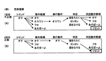
図20はご機嫌モードのときの各センサからの動作入力に応じて行われる動作及び表情の制御方法を示す図である。
【0126】
図20に示されるように、例えば、電子玩具10は、性格がご機嫌モードであるときにユーザーからの入力があると、次のような動作パターン(1)〜(12)に応じた姿勢、表情に変化させる。
(1)何も入力が無い場合、動作姿勢B(図9参照)から動作姿勢A(図8参照)に変化させ、表示部20の表示を丸目から消灯に変化させ、スピーカ26からいびきを発声させる。
(2)音センサ24のみから入力がある場合、動作姿勢B→Aに変化させ、表示部20の表示を消灯から泣き目に変化させ、スピーカ26から喜びの声を発声させる。
(3)光センサ25のみから入力がある場合、動作姿勢Bを維持し、表示部20で丸目を表示させ、スピーカ26からひとり言や効果音を発声させる。
(4)検出スイッチ59のみから入力がある場合、動作姿勢B→動作姿勢C(図10参照)→動作姿勢Bへ変化させ、表示部20の表示を消灯から丸目に変化させ、スピーカ26から喜びの声を発声させる。
(5)音センサ24及び光センサ25から入力がある場合、動作姿勢Bを維持し、表示部20の表示を丸目の点滅に切り替え、スピーカ26からワン▲1▼の声を発声させる。あるいは、動作姿勢B→C→Bへ変化させ、表示部20でハート目を表示させ、スピーカ26から遠吠え▲1▼を発声させる。
(6)音センサ24及び光センサ25、検出スイッチ59から入力がある場合、動作姿勢B→C→B→C→Bを行い、表示部20の表示を丸目からハート目に変化、あるいは表示部20でウインクを表示させると共にスピーカ26から笑い▲1▼の声を発声させる。
(7)光センサ25からの入力が繰り返しある場合、動作姿勢Bを維持し、表示部20で丸目を点滅させ、スピーカ26から喜びの声と笑い▲1▼の声を発声させる。
(8)音センサ24からの入力と光センサ25からの入力が繰り返しある場合、動作姿勢B→C→B→C→Bを行い、表示部20でハート目を点滅させ、スピーカ26からひとり言▲1▼〜▲3▼を発声させる。
(9)音センサ24、検出スイッチ59からの入力と光センサ25からの入力が繰り返しある場合、動作姿勢B→C→B→C→Bを行い、表示部20でハート目を点滅させ、スピーカ26から笑い声とメロディを発声させる。
(10)検出スイッチ59からの入力と光センサ25からの入力が繰り返しある場合、動作姿勢B→C→B→C→Bを行い、表示部20でハート目を点滅させ、スピーカ26から喜び声とメロディを発声させる。
(11)音センサ24、検出スイッチ59からの入力がある場合、動作姿勢B→Aに変化させ、表示部20で丸目を点滅させ、スピーカ26からひとり言▲2▼を発声させる。
(12)光センサ25、検出スイッチ59からの入力がある場合、動作姿勢B→C→B→C→Bを行い、表示部20でハート目を点滅させ、スピーカ26から喜び声とメロディを発声させる。
【0127】
図21は不機嫌モードのときの各センサからの動作入力に応じて行われる動作及び表情の制御方法を示す図である。
【0128】
図21に示されるように、例えば、電子玩具10は、性格が不機嫌モードであるときにユーザーからの入力があると、次のような動作パターン(1)〜(12)に応じた姿勢、表情に変化させる。
(1)何も入力が無い場合、動作姿勢B→Aに変化させ、表示部20の表示を丸目から消灯に変化させ、スピーカ26からいびきを発声させる。
(2)音センサ24のみから入力がある場合、動作姿勢B→Aに変化させ、表示部20の表示を消灯から怒り目に変化させ、スピーカ26から唸るような怒りの声を発声させる。
(3)光センサ25のみから入力がある場合、動作姿勢Bを維持し、表示部20で怒り目を表示させ、スピーカ26から低音化されたひとり言や効果音を発声させる。
(4)検出スイッチ59のみから入力がある場合、動作姿勢B→Aへ変化させ、表示部20の表示を消灯から怒りに変化させ、スピーカ26からため息を発声させる。
(5)音センサ24及び光センサ25から入力がある場合、動作姿勢Bを維持し、表示部20で怒り目を表示させると共に、スピーカ26で鳴き声▲2▼を発声させる。あるいは、動作姿勢Bを維持し、表示部20でウインクを表示させ、スピーカ26から笑い声▲2▼を発声させる。
(6)音センサ24及び光センサ25、検出スイッチ59から入力がある場合、動作姿勢B→C→Bを行い、表示部20の表示を怒り目から消灯に変化、あるいは表示部20でウインクを表示させると共にスピーカ26から鳴き声▲2▼を発声させる。あるいは、動作姿勢B→C→Bを行い、表示部20で丸目を点滅させ、スピーカ26から遠吠え▲2▼を発声させる。
(7)光センサ25からの入力が繰り返しある場合、動作姿勢Bを維持し、表示部20で丸目を点滅させ、スピーカ26からくしゃみを発声させる。
(8)音センサ24からの入力と光センサ25からの入力が繰り返しある場合、動作姿勢Bを維持し、表示部20で怒り目を点滅させ、スピーカ26から怒り+鳴き声▲2▼を発声させる。
(9)音センサ24、検出スイッチ59からの入力と光センサ25からの入力が繰り返しある場合、動作姿勢B→C→Bを行い、表示部20で丸目を点滅させ、スピーカ26から遠吠え▲1▼を発声させる。
(10)検出スイッチ59からの入力と光センサ25からの入力が繰り返しある場合、動作姿勢Bを維持し、表示部20で丸目を点滅させ、スピーカ26からウヒヒ▲2▼を発声させる。
(11)音センサ24、検出スイッチ59からの入力がある場合、動作姿勢B→Aに変化させ、表示部20で怒り目を表示させ、スピーカ26からため息を発声させる。
(12)光センサ25、検出スイッチ59からの入力がある場合、動作姿勢Bを維持し、表示部20で丸目を点滅させ、スピーカ26からウヒヒ▲2▼を発声させる。
このように電子玩具10は、コミュニカーションバイオリズムによる性格変化に基づいて性格が所定の周期でご機嫌モードあるいは不機嫌モードに切り替わるため、ユーザーが入力に対する反応を予測することが難しく、飽きさせることがない。
【0129】
また、各センサによる検出回数に応じてご機嫌モード及び/又は不機嫌モードの周期を変化させることもできる。そのため、ユーザーの接し方によってご機嫌モードの周期が長くなったり、不機嫌モードの周期が長くなったりするので、そのとき動作パターンを予測することが難しくなって意外な動作を行うことにより面白さを増大させることができる。
【0130】
ここで、制御部62のCPU80が実行する初期設定モードの制御処理について説明する。
【0131】
図22は初期設定処理を説明するためのフローチャートである。
【0132】
図22に示されるように、制御部62のCPU80は、S20において、新しい電池58が装着されたかどうかをチェックする。初めて電池58が電池収納部60に装着される場合、あるいは電池交換が行なわれた場合、S21に進み、メモリ(図示せず)に記憶されている初期値をリセットする。続いて、S22では、初期設定モードを設定する。尚、この初期設定モードのときは、性格が子犬モードになっており、比較的おとなしい性格になっている。
【0133】
次のS23では、スイッチ入力があったかどうかをチェックする。この場合、検出手段としての音センサ24と検出スイッチ59の検出動作を監視しており、各音センサ24、検出スイッチ59からの検出信号が出力されると、S24に進み、その検出回数nを積算し、その積算値(カウント値n+1)をメモリに記憶させる。
【0134】
次のS25では、所定時間T(例えば、T=1時間)が経過したかどうかをチェックする。従って、電池58が装着されてから1時間が経過するまで、S23〜S25の処理が繰り返される。
【0135】
そして、S25において、1時間が経過すると、S26に進み、音センサ24のカウント値nAと検出スイッチ59のカウント値nBとを比較する。
【0136】
次のS27では、音センサ24のカウント値nAが検出スイッチ59のカウント値nBより大きいとき(nA>nB)はS28に進み、性別データをオスに設定する。
【0137】
また、S27において、音センサ24のカウント値nAが検出スイッチ59のカウント値nBより大きくないとき、すなわち、▲1▼音センサ24のカウント値nAが検出スイッチ59のカウント値nBより小さいとき(nA<nB)、▲2▼音センサ24のカウント値nAが検出スイッチ59のカウント値nBと等しいとき(nA=nB)、▲3▼音センサ24のカウント値nA及び検出スイッチ59のカウント値nBとがゼロのとき(nA=0、nB=0)はS29に進み、性別データをメスに設定する。尚、上記▲2▼▲3▼の場合には、上記のように予め決められた性別に設定されるようにしても良いし、あるいは乱数を用いて性別が設定されるようにするもできる。 上記S28で、性別データがオスに設定されたとき、あるいはS29で性別データがメスに設定された後は、S30に進み、初期設定モードが解除される。そして、前述した図18に示すメインの制御処理に移行する。
【0138】
このようにして電池装着時にオスかメスかの初期設定が行われると、これ以降は設定された性別(個体差)に応じた表情や動作を行う。
【0139】
尚、性別の違いによる表情や動作としては、例えば図23(A)〜(B)に示す例がある。
【0140】
例えば、性別データがオスに設定された場合の特徴は、図23(A)に示されるように、▲1▼声が低音バージョンに設定、▲2▼目の通常パターンが図23(B)に示すパターンAに設定、▲3▼オスだけの特別曲を持っている。また、性別データがメスに設定された場合の特徴は、図23(A)に示されるように、▲1▼声がベーシックパターンに設定、▲2▼目の通常パターンが図23(C)に示すパターンBに設定、▲3▼メスだけの特別ダンスを持っている。このように、初期設定モードが設定されている間に音センサ24、検出スイッチ59により検出された検出回数のカウント値nA、nBに応じて性別(個体差)を設定するため、例えば初めて電池を装着されて初期設定モードが設定されている間にユーザーが接触する回数によって性別等の個体差を初期値として予め設定することができ、ユーザーが予想していないような個性的な表情や動作を演出することができる。
【0141】
また、上記説明では、音センサ24、検出スイッチ59の検出回数をカウントしてそのカウント値を比較して性別を設定したが、これ以外の検出手段としては、例えば、光センサ25などからの検出信号をカウントするようにしても良いのは勿論である。
【0142】
さらに、性別データがオスまたはメスに設定された場合の特徴は、図23(A)〜(C)に示す動作パターンに限らず、これ以外の表情や動作を行うように初期設定しても良いのは勿論である。
【0143】
図24は初期設定処理の変形例を説明するためのフローチャートである。
【0144】
図24に示されるように、制御部62のCPU80が実行する制御処理のうちS31〜S34の処理は前述したS20〜S23の処理と同一処理なので、その説明を省略する。
【0145】
S35においては、この場合、検出手段としての検出スイッチ59の検出動作を監視しており、検出スイッチ59からの検出信号が出力されると、S35に進み、その検出回数nを積算し、その積算値(カウント値n+1)をメモリに記憶させる。
次のS36では、所定時間T(例えば、T=1時間)が経過したかどうかをチェックする。従って、電池58が装着されてから1時間が経過するまで、S34〜S36の処理が繰り返される。
【0146】
そして、S36において、1時間が経過すると、S37に進み、検出スイッチ59のカウント値nを読み込む。S38において、検出スイッチ59のカウント値nが奇数かどうかをチェックする。
【0147】
次のS38において、検出スイッチ59のカウント値nが奇数であるときは、性別データをオスに設定する。
【0148】
また、S38で検出スイッチ59のカウント値nが奇数でないとき、すなわち、検出スイッチ59のカウント値nが偶数であるか、あるいはゼロであるため、S40に進み、性別データをメスに設定する。
【0149】
上記S39で、性別データがオスに設定されたとき、あるいはS40で性別データがメスに設定された後は、S41に進み、初期設定モードが解除される。そして、前述した図18に示すメインの制御処理に移行する。
【0150】
このようにして電池装着時にオスかメスかの初期設定が行われると、これ以降は設定された性別(個体差)に応じた表情や動作を行う(図23(A)〜(B)を参照)。従って、初期設定モードが設定されている間に検出された入力回数のカウント値が偶数か奇数かによって性別を設定するため、ユーザーの意思に関係なく設定された性別や性格に応じた表情や動作を演出することができる。すなわち、初期設定期間後のユーザーの接触に対応する表情や音声、動きに個体差が現れ、電子玩具があたかも動物のように性別や性格を持ったかのような演出が可能になる。
【0151】
また、上記説明では、検出スイッチ59の検出回数をカウントしてそのカウント値が奇数か偶数かを判定して性別を設定したが、これ以外の検出手段としては、例えば、音センサ24、光センサ25などからの検出信号をカウントしてそのカウント値が奇数か偶数かを判定して性別を設定するようにしても良いのは勿論である。
【0152】
尚、上記図20及ぶ図21において、スピーカ26からの音声は、各項目毎に複数種類が用意されており、且つ不機嫌モードのときはご機嫌モードのときよりも低音(低音も複数段階ある)で発声するようになっている。
【0153】
次に、本発明の第2実施例について説明する。
【0154】
図25は本発明の第2実施例に係る電子玩具の正面図である。また、図26は図25に示す電子玩具の側面図である。また、図27は図25に示す電子玩具の平面図である。また、図28は図25に示す電子玩具の背面図である。また、図29は図25に示す電子玩具の底面図である。また、図30は図25に示す電子玩具の斜視図である。尚、図25乃至図30において、前述した第1実施例の電子玩具10と同一構成部分には同一符号を付してその説明は省略する。
【0155】
図25乃至図30に示されるように、電子玩具90は、前述した電子玩具10と同様に頭部12、胴部14、脚部16〜19とを有する犬型玩具である。また、電子玩具90において、前述した電子玩具10と異なる動作としては、頭部12を左右方向に振ることができる点と、尻尾32を左右方向に揺動可能に設けられている点がある。
【0156】
さらに、電子玩具90は、胴部14の胸部分に2つのプッシュ式のモード選択スイッチ91A,91Bが設けられている。このモード選択スイッチ91A,91Bは、例えば後述する音声登録モードをスタートさせる際、あるいは性格育成モード、性格標準モード等を選択する際に何れか一方が選択的に操作される。また、モード選択スイッチ91A,91Bは、両方同時にオン操作されたときはメモリに記憶された制御データをリセットするためのリセットスイッチとして機能するものである。
【0157】
また、電子玩具90は、15種類の動作を行うことができる。
【0158】
図31は電子玩具90の動作種類と脚部16〜19の動作位置との組み合わせを示す図であり、(A)は動作種類と脚部16〜19の動作位置との組み合わせを示す図であり、(B)は各脚部16〜19の回動角度を示す図である。
【0159】
図31(A)(B)に示されるように、電子玩具90の前足となる脚部16,17は、垂直位置Aまたは水平位置Bの何れかに回動し、後足となる脚部18,19は垂直位置C、前傾斜位置D,水平位置E,後ろ傾斜位置Fの何れかに回動する。そして、脚部16,17が垂直位置Aまたは水平位置Bの何れかに回動し、脚部18,19が位置C〜Fの何れかに回動することにより立ち、座り、伏せ、威嚇、お手、良し、じたばた1、じたばた2、伸び1、伸び2、伸び3、腕立てフセ、バック1、バック2、演奏の各動作を行うことができる。
【0160】
例えば図32に示されるように、電子玩具90は、ユーザーから「立て」という言葉が入力されると、各脚部16〜19が垂直位置A、Cに回動して立ち状態となる。また、図33に示されるように、電子玩具90は、ユーザーから「お座り」という言葉が入力されると、脚部16、17が垂直位置Aに回動したまま後ろ側の脚部18、19が前傾斜位置Dに回動しておすわり状態となる。
【0161】
また、図34に示されるように、電子玩具90は、ユーザーから「お手」という言葉が入力されると、脚部17〜19が垂直位置A、Cに回動した状態で右前足となる脚部16を水平位置Bに回動してお手状態となる。また、図35に示されるように、電子玩具90は、ユーザーから「伏せ」という言葉が入力されると、各脚部16〜19が前方の水平位置B、Eに回動した伏せ状態となる。
【0162】
電子玩具90は、頭部12の前面に目の表情を表示する表示部20が設けられている。この表示部20は、前述したように複数の発光ダイオード(LED)を選択的に点灯させ、そのときの感情を目の表示パターンで表現できる。
【0163】
ここで、表示部20の表示パターンについて説明する。
【0164】
図36は表示部20の表示パターンの一例を示す図であり、(A)はニコ目を示す図、(B)は?目を示す図、(C)はハート目を示す図、(D)はジト目を示す図、(E)はマル目を示す図である。
【0165】
図36(A)〜(E)に示されるように、第2実施例の表示部20では、例えば、5種類の表示パターン▲1▼〜▲5▼を選択的に表示することが可能である。
【0166】
表示パターン▲1▼では、円弧形のニコ目パターンが発光部92a,92bで発光する。
【0167】
表示パターン▲2▼では、クエッションマーク状の?目パターンが発光部94a,94bで発光する。
【0168】
表示パターン▲3▼では、ハート形のハート目パターンが発光部96a,96bで発光する。
【0169】
表示パターン▲4▼では、三日月形のジト目パターンが発光部98a,98bで発光する。
【0170】
表示パターン▲5▼では、上記ニコ目パターンとジト目パターンとが同時に表示されたマル目パターンが発光部100a,100bで発光する。
【0171】
次に、電子玩具90に電池を装着した時に実行される音声登録モードについて説明する。
【0172】
図37は音声登録を説明するための図であり、(A)は音声登録の使用される登録単語の一例を示す図、(B)は音声登録の手順を説明するためのフローチャート、(C)は音声登録失敗例を説明するためのフローチャート、(D)は音声登録成功例を説明するためのフローチャートである。
【0173】
図37(A)に示されるように、本実施例では、▲1▼犬の名前、▲2▼お手、▲3▼伏せ、▲4▼お座り、▲5▼よしよし、▲6▼あそぼーよの6種類の言葉が音声登録用の単語として用いられる。
【0174】
次に、制御部62のCPU80が実行する音声登録の手順を説明する。
【0175】
図37(B)に示されるように、先ず、S51で電池を電子玩具90に装着した後、モード選択スイッチ91Aがオンに操作されると、音声登録モードをスタートする。次のS52では、電子玩具90のスピーカ26から「名前を言ってください」といったメッセージを発声するとともに表示部20にニコ目(図36(A)参照)を点滅表示する。これに対し、ユーザーが犬の名前(例えば、プーチ)を言うと、音センサ24に犬の名前が入力される。
【0176】
犬の名前の音声入力が登録されると、S53に進み、スピーカ26から「お手と言ってください」といったメッセージを発声するとともに表示部20にニコ目(図36(A)参照)を点滅表示する。これに対し、ユーザーが「お手」を言うと、音センサ24に「お手」といった言葉が入力される。
【0177】
お手の音声入力が登録されると、S54に進み、スピーカ26から「お座りと言ってください」といったメッセージを発声するとともに表示部20にニコ目(図36(A)参照)を点滅表示する。これに対し、ユーザーが「お座り」を言うと、音センサ24に「お座り」といった言葉が入力される。
【0178】
お座りの音声入力が登録されると、S55に進み、スピーカ26から「伏せと言ってください」といったメッセージを発声するとともに表示部20にニコ目(図36(A)参照を点滅表示する。これに対し、ユーザーが「伏せ」を言うと、音センサ24に「伏せ」といった言葉が入力される。
【0179】
伏せの音声入力が登録されると、S56に進み、スピーカ26から「よしよしと言ってください」といったメッセージを発声するとともに表示部20にニコ目(図36(A)参照)を点滅表示する。これに対し、ユーザーが「よしよし」を言うと、音センサ24に「よしよし」といった言葉が入力される。
【0180】
よしよしの音声入力が登録されると、S57に進み、スピーカ26から「あそぼーよと言ってください」といったメッセージを発声するとともに表示部20にニコ目(図36(A)参照)を点滅表示する。これに対し、ユーザーが「あそぼーよ」を言うと、音センサ24に「あそぼーよ」といった言葉が入力される。
【0181】
あそぼーよの音声入力が完了すると、S58に進み、スピーカ26から例えば、ピロリンといったような電子音が発声されて音声登録モードが終了する。
【0182】
このように、上記▲1▼犬の名前、▲2▼お手、▲3▼伏せ、▲4▼お座り、▲5▼よしよし、▲6▼あそぼーよの6種類の言葉がユーザーの音声で登録される。この後は、登録されたユーザーの音声が他の音声よりも優先される。
【0183】
次に、音声登録を失敗した場合について説明する。
【0184】
図37(C)に示されるように、S61でスピーカ26から「名前を言ってください」といったメッセージを発声するとともに表示部20にニコ目(図36(A)参照)を点滅表示した場合、ユーザーが犬の名前(例えば、プーチ)を言っても音センサ24から犬の名前が入力されず登録されなかったときは、S62に進み、スピーカ26からブブーといったエラー音を発声させると共に、表示部20に?目(図36(B)参照)を表示する。これにより、ユーザーは、音声登録が失敗したことを確認できる。
【0185】
そして、S63では「もう一度名前を言って下さい」といったメッセージをスピーカ26から発声させる。
【0186】
また、音声登録が成功した場合の動作について説明する。
【0187】
図37(D)に示されるように、S71でスピーカ26から「名前を言ってください」といったメッセージを発声するとともに表示部20にニコ目(図36(A)参照)を点滅表示した場合、ユーザーが言った犬の名前(例えば、プーチ)が登録されたときは、S72に進み、スピーカ26からピンポンといった電子音を発声させると共に、表示部20にハート目(図36(C)参照)を表示する。これにより、ユーザーは、音声登録が成功したことを確認できる。
【0188】
次に、電子玩具90の音声登録モードが完了すると、電子玩具90の性格を登録する性格登録モードに移行する。
【0189】
ここで、図38乃至図40を参照して電子玩具90の性格登録モードについて説明する。図38は性格形成の条件の一例を説明するための図であり、(A)は性格特徴を示す図、(B)は性格形成パラメータMAPの一例を示す図、(C)は性格変化の条件の一例を示す図である。
【0190】
図38(A)に示されるように、電子玩具90で登録可能な性格は、▲1▼駄犬(特徴は例えば、下品な声で下品な歌を歌う、主人の指示内容を聞かず異なる行動を行ったり、寝てばかりいる)、▲2▼忠犬(特徴は主人の指示内容に忠実な行動を行うと共に、歌も歌える)▲3▼芸犬(特徴は忠犬と同様に忠実な性格と愛嬌を併せ持つ、例えば「あそぼーよ」と言うと特別な芸を行うなど)の3種類がある。
【0191】
図38(B)に示されるように、電子玩具90の性格を形成する性格形成パラメータMAP102には、忠犬パラメータと芸犬パラメータとがある。この性格形成パラメータは、ユーザーが電池を装着した後、所定時間(例えば、4時間)以内に行った接触(しつけ)の仕方や回数に応じてポイントがカウントされる。
忠犬パラメータとしてカウントされる接触(しつけ)方法は、例えばお手、お座り、伏せ等の呼びかけがある。また、芸犬パラメータとしてカウントされる接触(しつけ)方法としては、「あそぼうよ」という呼びかけがある。
【0192】
例えば、ユーザーがお手と言った場合、電子玩具90が図34に示すお手の動作を行った場合、お手のポイントが増加される。このように電子玩具90がユーザーの命令に従うと性格形成パラメータMAP102の各項目が丸印で埋まり忠犬パラメータ及び芸犬パラメータのポイントが増加する。
【0193】
そして、図38(C)に示されるように、性格変化の条件としては、例えば、4時間以内に性格形成パラメータMAP102のすべての項目が25ポイントになった場合、電子玩具90の性格は芸犬となる。また、4時間以内に性格形成パラメータMAP102のうち忠犬パラメータの各項目が25ポイントになった場合、電子玩具90の性格は忠犬となる。また、4時間以内に性格形成パラメータMAP102のうち忠犬パラメータ及び芸犬パラメータの各項目が25ポイントに達していない場合、電子玩具90の性格は駄犬となる。
【0194】
図39は性格登録動作の一例を説明するための図であり、(A)は不正解の動作例を示す図、(B)は正解の動作例を示す図である。
【0195】
図39(A)に示されるように、例えば、ユーザーが「お手」と命令したのに動作候補のなかからオスワリが選択されて電子玩具90がオスワリの動作(図33参照)を行った場合、間違った動作をしたので、ユーザーは電子玩具90の頭部12の上面に設けられたスピーカ26をたたく。これにより、スピーカ26の下方に設けられた検出スイッチ59が強い力で押圧されてオンに操作される。
【0196】
判定処理で検出スイッチ59が強い力で押圧されたことが検出されると、性格形成パラメータMAP102のポイントとして登録されず、制御部62は次回動作候補を選択する。
【0197】
しかしながら、図39(B)に示されるように、例えば、ユーザーが「お手」と命令したのに動作候補のなかからオテが選択されて電子玩具90がオテの動作(図34参照)を行った場合、ユーザーがヨシヨシと言うと、音センサ24に「よしよし」といった言葉が入力される。これで、制御部62は、次回動作候補からオテをリセットして性格形成パラメータMAP102のポイントとして登録する。
図40は上記性格形成パラメータMAP102に登録された忠犬パラメータI及び芸犬パラメータIIのポイント数の変化(増加)に応じて設定される電子玩具90の性格を示すグラフであり、(A)は忠犬設定モードを示すグラフ、(B)は芸犬設定モードを示すグラフ、(C)(D)は駄犬設定モードを示すグラフである。尚、性格形成は、小犬の時期(例えば、電池装着から4時間)に行われる。
【0198】
図40(A)に示されるように、電子玩具90は、電池が装着されたときは幼犬であり、学習機能が機能しないので、ユーザーの命令に対して動作が予測できない。そして、幼犬期(未熟期)が過ぎると、小犬期(育成時期)に入り性格形成が可能になる。そして、ユーザーが小犬期に接触した回数と接触方法に応じて性格形成パラメータMAP102に登録された忠犬パラメータI及び芸犬パラメータIIのポイント数が変化(増加)する。
【0199】
例えば、小犬期に忠犬パラメータIのポイントが芸犬パラメータIIのポイントよりも先に目標(ポイント25)を達成すると、成犬期(育成完了時期)に入ったとき電子玩具90の性格は忠犬となり、忠犬フラグ(第1の制御フラグ)がセットされる。
【0200】
また、図40(B)に示されるように、小犬期に芸犬パラメータIIのポイントが忠犬パラメータIのポイントよりも先に目標(ポイント25)を100%達成すると、成犬期に入ったとき電子玩具90の性格は芸犬となり、芸犬フラグがセットされる。
【0201】
また、図40(C)に示されるように、小犬期の当初は芸犬パラメータIIのポイントが忠犬パラメータIのポイントと同じように増加し、途中から芸犬パラメータIIが急激に増加して目標(ポイント25)を達成すると、成犬期に入ったとき電子玩具90の性格は駄犬となり、駄犬フラグ(第2の制御フラグ)がセットされる。
【0202】
また、図40(D)に示されるように、小犬期の当初は芸犬パラメータIIのポイントが忠犬パラメータIのポイントよりも低く変化し、途中から芸犬パラメータIIが急激に増加して忠犬パラメータIのポイントより大きな値に増加した場合、成犬期に入ったとき電子玩具90の性格は駄犬となる。
【0203】
このように、電子玩具90が小犬期にユーザーの接触方法や接触回数などによって忠犬パラメータI及び芸犬パラメータIIのポイント数が変化(増加)して電子玩具90の性格が忠犬、芸犬、駄犬の何れかに設定されるため、ユーザーが電池装着後の所定時間内に十分に接触した場合は忠犬または芸犬に育成することができ、接触回数が少ないときは駄犬になってしまうので、育成方法を楽しむことができる。
【0204】
次に、性格育成時期が終わって電子玩具90が成犬になったときの動作制御を行うための感情パラメータについて説明する。
【0205】
この感情パラメータは、時間の経過に伴なって変化する気分パラメータと、えさの供給回数によって変化する満腹パラメータとを有する。
【0206】
図41は気分パラメータを説明するための図であり、(A)は気分パラメータのレベルを示す図、(B)は各レベルの状態を示す図、(C)は気分パラメータのプラス条件を示す図、(D)は気分パラメータのマイナス条件を示す図である。
【0207】
図41(A)に示されるように、気分パラメータの値PAは、レベル1〜5の5段階に変化するように設定されている。レベル1ではPA=0〜20、レベル2ではPA=20〜40、レベル3ではPA=40〜60、レベル4ではPA=60〜80、レベル5ではPA=80〜100、100〜127となる。
【0208】
尚、スタート当初は、気分パラメータの値PAは、初期値がPA=50に登録されている。
【0209】
図41(B)に示されるように、気分パラメータの値PAがレベル1であるとき、電子玩具90は制御モードが超不機嫌な状態となる。また、気分パラメータの値PAがレベル2であるとき、電子玩具90は制御モードが不機嫌な状態となる。また、気分パラメータの値PAがレベル3であるとき、電子玩具90は制御モードが普通(ノーマル)の状態となる。また、気分パラメータの値PAがレベル4であるとき、電子玩具90は制御モードがゴキゲンな状態となる。また、気分パラメータの値PAがレベル5であるとき、電子玩具90は制御モードが超ゴキゲンの状態となる。
【0210】
図41(C)に示されるように、ユーザーが電子玩具90の頭部12をなでると気分パラメータの値PAが2ポイント増加され、ユーザーからの音声による命令で動作した後に誉められたとき(例えば、「よしよし」等の言葉)は気分パラメータの値PAが4ポイント増加される。また、ユーザーからの音声による命令で動作した後に駄目と言われたときは気分パラメータの値PAが4ポイント増加される。
【0211】
図41(D)に示されるように、ユーザーが電子玩具90の頭部12をたたいたときは、気分パラメータの値PAが1ポイントマイナスされる。また、エサの供給時間が経過(例えば、1分間毎)するとともに満腹レベルが段階的に低下して気分パラメータの値PAが満腹レベル5では2ポイントマイナス、満腹レベル4では4ポイントマイナス、満腹レベル3では6ポイントマイナス、満腹レベル2では8ポイントマイナス、満腹レベル1では10ポイントマイナスとなる。従って、気分パラメータは、満腹パラメータの値PBに応じて変化するように設定されている。
【0212】
また、電子玩具90が眠る時点で気分パラメータの値PAが100を越えていた場合は、レベル5であるのでPA=100に修正する。
【0213】
また、気分パラメータの値PAが127(レベル5の最大値)を越えた場合は、超ゴキゲン状態がかなり続いたので、PA=20に修正して超不機嫌状態に変化させる。
【0214】
図42は満腹パラメータを説明するための図であり、(A)は満腹パラメータのレベルを示す図、(B)は各レベルの状態を示す図、(C)は満腹パラメータのプラス条件を示す図、(D)は満腹パラメータのマイナス条件を示す図である。
【0215】
図42(A)に示されるように、満腹パラメータの値PBは、レベル1〜5の5段階に変化するように設定されている。レベル1ではPB=0〜20、レベル2ではPB=20〜40、レベル3ではPB=40〜60、レベル4ではPB=60〜80、レベル5ではPB=80〜100、100〜127となる。
【0216】
尚、スタート当初は、満腹パラメータの値PBの初期値がPB=50に登録されている。
【0217】
図42(B)に示されるように、気分パラメータの値PBがレベル1であるとき、電子玩具90は制御モードが超空腹な状態となる。また、満腹パラメータの値PBがレベル2であるとき、電子玩具90は制御モードが空腹な状態となる。また、満腹パラメータの値PBがレベル3であるとき、電子玩具90は制御モードが普通(ノーマル)の状態となる。また、満腹パラメータの値PBがレベル4であるとき、電子玩具90は制御モードが満腹状態となる。また、満腹パラメータの値PBがレベル5であるとき、電子玩具90は制御モードが超満腹状態となる。
【0218】
尚、満腹パラメータの値PBがPB=127以上になると、おなかがパンクするため、PB=20に減少させる。
【0219】
図42(C)に示されるように、ユーザーが電子玩具90にエサを与えると満腹パラメータの値PBが4ポイント増加される。
【0220】
図42(D)に示されるように、電子玩具90がエサを要求する音声を発したとき、あるいはエサを要求する動作を行ったときは、満腹パラメータの値PBが1ポイントマイナスされる。
【0221】
また、電子玩具90が空腹になってエサを要求してから所定時間(例えば、1分間)が経過する度に満腹パラメータの値PBが4ポイントマイナスされる。従って、ユーザーが定期的にエサを与えると満腹パラメータの値PBが増加し、ユーザーがエサを与えないと満腹パラメータの値PBが減少して空腹になるとともに、気分パラメータPAも減少して不機嫌な状態に変化する。
【0222】
尚、エサとしては、例えば骨に似た形状の樹脂材に磁石を埋め込み、電子玩具90の口31の内部に磁気センサを設けることによりエサが与えられたことを検出することができる。あるいは、電子玩具90の口31の内部に光センサを設けてエサを検出するようにして良い。
【0223】
図43は気分パラメータの変化の一例を示すグラフである。
【0224】
図43に示されるように、時間0からt1の間は、ユーザーがかまってあげているので気分パラメータの値PAが上昇する。また、時間t1からt2の間は、ユーザーがかまってあげないので気分パラメータの値PAが低下する。
【0225】
時間t3では、気分パラメータの値PAがPA=127以上になるため、満腹パラメータの値PBによって急激に低下する。これにより、超御機嫌モードが連続してユーザーが飽きてしまうのを防止する。
【0226】
図44は満腹パラメータの値PBに応じた気分パラメータの変動値の一例を示す図である。
【0227】
図44に示されるように、本実施例では、▲1▼満腹パラメータの値PBが0〜20のときは、気分パラメータの値PAの変動値が100ポイントマイナス、▲2▼満腹パラメータの値PBが20〜40のときは、気分パラメータの値PAの変動値が90ポイントマイナス、▲3▼満腹パラメータの値PBが40〜60のときは、気分パラメータの値PAの変動値が80ポイントマイナス、▲4▼満腹パラメータの値PBが60〜80のときは、気分パラメータの値PAの変動値が70ポイントマイナス、▲5▼満腹パラメータの値PBが80〜127のときは、気分パラメータの値PAの変動値が60ポイントマイナスとなる。
【0228】
従って、空腹なときほど気分パラメータのマイナス変動値が大きく、満腹なときほど気分パラメータのマイナス変動値が小さい。よって、気分パラメータは、ユーザーからの音声入力や頭部12をなでたりするとともに、エサの供給回数や供給間隔によって変動する満腹パラメータに影響されて変動する。そのため、ユーザーは、実際の犬と同様にエサを与える時間や回数にも注意する必要があり、実際の犬を飼っているような感覚で電子玩具90と遊ぶことができる。
【0229】
ここで、上記のように構成された電子玩具90の制御部62が実行する制御処理について説明する。
【0230】
図45は電子玩具90の制御部62が実行するメイン処理のフローチャートである。また、図46は図45の処理に続いて実行されるメイン処理のフローチャートである。
【0231】
図45に示されるように、電子玩具90に電池が装着されると、S80で音声認識用の言葉を登録する。この音声登録処理は、前述した図37(A)〜(D)を参照のこと。
【0232】
次のS81では、電子玩具90の性格を小犬期に育成する性格育成モードと、性格育成を省略して性格標準モードとの何れか一方を選択する。例えば、S81において、ユーザーがモード選択スイッチ91Aをオンに操作したときは、性格育成モードが選択され、ユーザーがモード選択スイッチ91Bをオンに操作したときは、性格標準モードが選択される。
【0233】
従って、S81において、モード選択スイッチ91Aがオンになったときは、S82に進み、性格育成モードがセットされる。また、S81において、モード選択スイッチ91Bがオンになったときは、S83に進み、性格標準モードとして設定された忠犬モードがセットされる。
【0234】
S83で忠犬モードがセットされたときは、S84で忠犬モードの制御データをROM82から読み込む。続いて、S85では忠犬モードの制御が行われる。そして、S86でリセットされるまで、忠犬モードの制御が継続される。
【0235】
また、上記S82で性格育成モードがセットされると、S87に進み、幼犬期の動作制御を行う。この幼犬期の動作制御としては、各音声入力や頭部12をなでるなどの入力に対する動作、入力がないときの動作、気分パラメータ及び満腹パラメータに基づく動作などを行う。次のS88では、幼犬期が終了したかどうかをチェックする。
【0236】
S88で幼犬期が終了すると、S89に進み、小犬期の動作制御を行う。この小犬期の動作制御は、前述した学習モード(図38乃至図40参照)であり、頭部12のスイッチ、音声、エサ等の各入力に対する処理、入力がないときの処理、気分パラメータ及び満腹パラメータの処理、言葉に対する性格形成パラメータMAP102への記入(忠犬パラメータ処理)、芸犬パラメータ処理などがある。 次のS90では、小犬期が終了したかどうかをチェックする。この小犬期が終了するまで、S88の小犬期の動作制御が実行される。
【0237】
S90において、小犬期が終了すると、S91に進み、上記S88の処理で育成された性格データ(忠犬パラメータ、芸犬パラメータ)に応じた忠犬、芸犬、駄犬の何れかのフラグをセットする(図40(A)〜(D)参照)。
【0238】
次のS92(図46参照)では、忠犬フラグがセットされたかどうかをチェックする。S92において、忠犬フラグがセットされたときは、S93に進み、芸犬フラグがセットされたかどうかをチェックする。S93において、芸犬フラグがセットされたときは、S94に進み、芸犬モードを設定した後、S95で芸犬モードの制御データをROM82から読み込む。続いて、S96では芸犬モードの制御が行われる。そして、S97でリセットされるまで、芸犬モードの制御が継続される。
【0239】
また、上記S92において、忠犬フラグがセットされていないときは、駄犬フラグがセットされているものと判断してS98に進み、駄犬モードを設定した後、S99で駄犬モードの制御データをROM82から読み込む。続いて、S100では駄犬モードの制御が行われる。そして、S101でリセットされるまで、駄犬モードの制御が継続される。
【0240】
また、上記S93において、芸犬フラグがセットされていないときは、上記S83に移行してS83〜S86の処理を実行する。
【0241】
このように、第2実施例では、小犬期にユーザーの対応の仕方に応じた性格育成処理を行うことによって個性的な性格データ(忠犬パラメータ、芸犬パラメータ)を形成することができ、実際のペットを飼育するのと同じような感覚で遊ぶことができる。
【0242】
また、上記実施例では、犬形の電子玩具を一例として説明したが、これに限らず、他の動物、例えば猫、虎、ライオン、猿、馬、象、キリン等の動物に似せた電子玩具にも適用できるのは勿論である。
【0243】
【発明の効果】
上述の如く、上記請求項1記載の発明によれば、目の表現パターンの一つまたは複数に対応するデータを選択して当該データに基づき光源の一つまたは複数を選択的に点灯し、当該点灯した光源に対応するプレートに光を入射して穴によって構成されるパターンを表示することによって、選択されたデータに対応する目の表現パターンがカバー部材を介して目視可能に点灯するため、目の表現パターンを予測することが難しいので、長期間遊んでも飽きることがない。
【0244】
また、請求項2記載の発明によれば、センサからの信号に応答して、複数の表現パターンデータの何れかを選択し、選択された当該表現パターンデータに基づき選択された光源を点灯し当該点灯した光源に対応する板状部材に入射される光によって対応する当該板状部材に設けられた一群の小孔を発光させることで表示部に選択された目の表現パターンを表示する制御と、複数の動作パターンの何れかを選択し、当該選択された動作パターンデータに基づき前記脚部に対応する動作を行わせる制御とを行うため、センサからの入力のタイミングによって異なる動作を行うようにできる。さらに、動作パターンを予測することが難しいので、入力に対して意外な行動を起こすように制御できるので、長期間遊んでも飽きることがない。
【0245】
また、上記請求項3記載の発明によれば、脚部がカム機構から伝達される回転力によって動作制御されるため、表示部に表示される目の表現パターンに連動して脚部を動作させて長期間遊んでも飽きることがない。
【0246】
また、上記請求項4記載の発明によれば、頭部に設けられた耳形状部が伝達機構によって伝達される回転力によって駆動されるため、脚部を駆動する駆動機構により耳形状部も動作させることができ、入力に対して意外な行動を起こすように制御できるので、長期間遊んでも飽きることがない。
【0247】
また、上記請求項5記載の発明によれば、初期設定手段が初期設定モードを設定している期間にカウンタにより得られたカウント数に応じた性格に関するデータを登録し、制御手段は、性格形成手段によって登録された性格に関するデータに基づき複数の光源を選択的に点灯させる制御および脚部の動作の制御を行うため、初期設定期間後のユーザーの接触に対応する表情や音声、動きに個体差が現れ、電子玩具があたかも動物のように性別や性格を持ったかのような演出が可能になる。
【0249】
また、上記請求項6記載の発明によれば、性格形成手段がカウンタから得られたカウント値が偶数であるか奇数であるかに基づき性格に関するデータを登録するため、複雑な演算を行なわずに異なる性格を適宜設定することができる。
【図面の簡単な説明】
【図1】本発明の第1実施例に係る電子玩具の正面図である。
【図2】図1に示す電子玩具の側面図である。
【図3】図1に示す電子玩具の平面図である。
【図4】図1に示す電子玩具の背面図である。
【図5】図1に示す電子玩具の底面図である。
【図6】図1に示す電子玩具の斜視図である。
【図7】脚部16〜19の回動方向及び回動角度を示す電子玩具10の側面図である。
【図8】電子玩具10が寝ている姿勢Aのときの動作状態を示す側面図である。
【図9】電子玩具10が立っている姿勢Bのときの動作状態を示す側面図である。
【図10】電子玩具10が前のめり姿勢Cのときの動作状態を示す側面図である。
【図11】電子玩具10の内部構造を示す正面縦断面図である。
【図12】電子玩具10の内部構造を示す側面縦断面図である。
【図13】電子玩具10の内部構造を示す平面縦断面図である。
【図14】表示部20に組み込まれる赤色アクリル板71〜74を個別に示す正面図である。
【図15】表示部20で発光表示される表示パターンの組み合わせを示す図である。
【図16】電子玩具10の制御系統の構成を示すブロック図である。
【図17】制御部62の構成を示すブロック図である。
【図18】制御部62のCPU80が実行する制御処理を説明するためのフローチャートである。
【図19】ペットバイオリズム及びコミュニケーションバイオリズムの変化を示すグラフである。
【図20】ご機嫌モードのときの各センサからの動作入力に応じて行われる動作及び表情の制御方法を示す図である。
【図21】不機嫌モードのときの各センサからの動作入力に応じて行われる動作及び表情の制御方法を示す図である。
【図22】初期設定処理を説明するためのフローチャートである。
【図23】性格データがオスまたはメスに設定されたときの性別毎の特徴を示す図であり、(A)はオスとメスの特徴を示す一覧、(B)は性格データがオスに設定された場合の目の表情を示す図、(C)は性格データがメスに設定された場合の目の表情を示す図である。
【図24】初期設定処理の変形例を説明するためのフローチャートである。
【図25】本発明の第2実施例に係る電子玩具の正面図である。
【図26】図25に示す電子玩具の側面図である。
【図27】図25に示す電子玩具の平面図である。
【図28】図25に示す電子玩具の背面図である。
【図29】図25に示す電子玩具の底面図である。
【図30】図25に示す電子玩具の斜視図である。
【図31】電子玩具90の動作種類と脚部16〜19の動作位置との組み合わせを示す図であり、(A)は動作種類と脚部16〜19の動作位置との組み合わせを示す図であり、(B)は各脚部16〜19の回動角度を示す図である。
【図32】電子玩具90の立ち動作を説明するための側面図である。
【図33】電子玩具90のお座り動作を説明するための側面図である。
【図34】電子玩具90のお手動作を説明するための側面図である。
【図35】電子玩具90の伏せ動作を説明するための側面図である。
【図36】表示部20の表示パターンの一例を示す図であり、(A)はニコ目を示す図、(B)は?目を示す図、(C)はハート目を示す図、(D)はジト目を示す図、(E)はマル目を示す図である。
【図37】音声登録を説明するための図であり、(A)は音声登録の使用される登録単語の一例を示す図、(B)は音声登録の手順を説明するためのフローチャート、(C)は音声登録失敗例を説明するためのフローチャート、(D)は音声登録成功例を説明するためのフローチャートである。
【図38】性格形成の条件の一例を説明するための図であり、(A)は性格特徴を示す図、(B)は性格形成パラメータMAPの一例を示す図、(C)は性格変化の条件の一例を示す図である。
【図39】性格登録動作の一例を説明するための図であり、(A)は不正解の動作例を示す図、(B)は正解の動作例を示す図である。
【図40】性格形成パラメータMAP102に登録された忠犬パラメータI及び芸犬パラメータIIのポイント数の変化(増加)に応じて設定される電子玩具90の性格を示すグラフであり、(A)は忠犬設定モードを示すグラフ、(B)は芸犬設定モードを示すグラフ、(C)(D)は駄犬設定モードを示すグラフである。
【図41】気分パラメータを説明するための図であり、(A)は気分パラメータのレベルを示す図、(B)は各レベルの状態を示す図、(C)は気分パラメータのプラス条件を示す図、(D)は気分パラメータのマイナス条件を示す図である。
【図42】満腹パラメータを説明するための図であり、(A)は満腹パラメータのレベルを示す図、(B)は各レベルの状態を示す図、(C)は満腹パラメータのプラス条件を示す図、(D)は満腹パラメータのマイナス条件を示す図である。
【図43】気分パラメータの変化の一例を示すグラフである。
【図44】満腹パラメータの値PBに応じた気分パラメータの変動値の一例を示す図である。
【図45】電子玩具90の制御部62が実行するメイン処理のフローチャートである。
【図46】図45の処理に続いて実行されるメイン処理のフローチャートである。
【符号の説明】
10 電子玩具
12 頭部
14 胴部
16〜19 脚部
20 表示部
22 鼻部
24 音センサ
25 光センサ
26 スピーカ
28 身部
30 顎部
31 口
32 尻尾
36 モータ
38 伝達機構
40 駆動ギヤ
42 第1の伝達ギヤ
44 第2の伝達ギヤ
46 第3の伝達ギヤ
48 第1のカムギヤ
52 第4の伝達ギヤ
54 第2のカムギヤ
56 伝達経路
58 電池
59 検出スイッチ
62 制御部
64 基板
71〜74 赤色アクリル板
75〜79 発光ダイオ−ド(LED)
80 CPU
82 ROM
82A 動作制御プログラム
82B 姿勢制御データ
82C 音声制御データ
82D 表示制御データ
82E ペットバイオリズムデータ
82F バイオリズム補正データ
84 RAM
84A カウンタ
84B コミュニケーションバイオリズムデータ
86 タイマ
90 電子玩具
91A,91B 選択スイッチ
102 性格形成パラメータMAP[0001]
BACKGROUND OF THE INVENTION
The present invention relates to an electronic toy that is controlled so as to perform an arbitrary operation in response to an external voice or contact.IngredientsRelated.
[0002]
[Prior art]
Traditionally, animal stuffed animals such as dogs, cats and bears have been widely used as animal toys. In addition, a motor and a speaker are built in a synthetic resin body that is shaped like an animal stuffed animal or animal, and performs a predetermined operation such as moving a foot or a mouth by touching and pressing the head. There is also an animal toy configured to utter a predetermined cry.
[0003]
In this type of animal toy, the same operation is repeated and the same cry is repeatedly uttered, so the user often gets bored quickly.
[0004]
On the other hand, if an operation is selected at random, the operation expected by the user may not occur and the user may get bored immediately.
[0005]
Development of an electronic toy equipped with a microcomputer for controlling such a conventional animal toy so as to perform various operations so as not to get tired of the user has been promoted.
[0006]
As an electronic toy, for example, when the head is stroked, hugged, or voiced, a certain kind of operation (for example, an operation that utters a pre-stored word from a speaker or shakes the body by a command of a microcomputer) Etc.). Also, with this type of electronic toy, the number of strokes of the head, the number of times it is picked up, the number of times it is spoken is counted, and for example, as the count value increases, the words uttered from the speaker are changed step by step into a cute expression. I have control.
[0007]
[Problems to be solved by the invention]
In the above-mentioned conventional electronic toys, the spoken words gradually change into cute expressions as the number of strokes of the head, the number of times of picking up, the number of times of calling, etc. increase, so the movement pattern can be predicted. End up.
[0008]
Therefore, the conventional electronic toy has a problem that the user gets bored in a relatively short period of time because it becomes clear what word is spoken next as the time of contact increases.
[0009]
Accordingly, the present invention provides an electronic toy that solves the above-mentioned problems by changing the operation pattern in accordance with the result of combining parameters that change depending on the number of times and time of input such as external voice and contact.IngredientsThe purpose is to provide.
[0010]
[Means for Solving the Problems]
In order to solve the above problems, the present invention has the following features.
The invention according to
The invention according to
According to a third aspect of the present invention, the drive mechanism is driven by a drive motor, a transmission mechanism connected to the drive motor and transmitting a rotational force of the drive motor, and a rotational force transmitted by the transmission mechanism. A cam mechanism, wherein the leg portion is configured to be controlled by a rotational force transmitted from the cam mechanism.
The invention according to
The invention according to
The invention described in
[0011]
Furthermore, the present invention has the following features.
(1) BookAccording to the present invention, when a detection signal is output from the detection means, any one of a plurality of operation patterns stored in the storage means is selected based on the count value of the counter means and the value of the first parameter set by the parameter change means. The operation pattern information is selected. For example, when there is an input such as an external voice or a touch, a different operation can be performed depending on the input timing. Furthermore, since it is difficult to predict an operation pattern, it can be controlled to cause an unexpected action with respect to an input, so that it does not get bored even if it plays for a long time.
[0012]
(2)Also,BookThe invention repeats the mood mode and the mood mode alternately at a predetermined cycle based on a control parameter that changes with the passage of time, and switches to the mood mode or the mood mode depending on the input timing, and is not predicted. It is possible to increase the fun by performing the operation.
[0013]
(3)Also,BookThe invention changes the period of the mood mode and / or the mood mode according to the number of detections, and the period of the mood mode becomes longer or the period of the mood mode becomes longer depending on how the user touches. At that time, it becomes difficult to predict the operation pattern, and it is possible to increase the fun by performing an unexpected operation.
[0014]
(4)Also,BookThe present invention selects a special operation pattern when the value indicating the change in the first parameter matches the count value of the counter means, and the normal operation is performed by an unexpected reaction different from the normal operation. You can enjoy it even more.
[0015]
(5)Also,BookThe invention detects external voices, external contacts and changes in ambient light intensity, and recognizes being cute and can be operated according to the detected content.Become.
[0016]
(6)Also,BookThe invention repeats the same operation together with the timing when the operation pattern selected according to the number of times of sound detection, the number of contact detections, and the number of light changes counted by the first to third counter means is changed. In this way, it is possible to produce the fun of the reaction to the input.
[0017]
(7)Also,BookIn the invention, the selection means selects the information of the special operation pattern when the value indicating the change of the parameter matches the count value of the first to third counter means, and differs depending on each count value. It is possible to enjoy more than selecting a special operation pattern and performing an unexpected operation.
[0018]
(8)Also,BookThe invention includes a posture action pattern stored in the first storage unit based on a count value of the counter unit and a value of the first parameter set by the parameter changing unit, a voice pattern stored in the second storage unit, An arbitrary action is selected from the facial expression pattern data stored in the third storage unit,(1)The effects and effects of can be achieved.
[0019]
(9)Also,BookThe invention selects the combination of the posture action pattern, the voice pattern, and the expression pattern based on the count value of the counter means and the value of the first parameter set by the parameter changing means.(1)The effects and effects of can be achieved.
[0020]
(10)Also,BookIn the invention, the expression pattern is operated so as to include at least an operation pattern that changes the size or shape of the eyes, and is based on the count value of the counter means and the value of the first parameter set by the parameter changing means. By changing the size or shape of the eye, it is possible to produce a facial expression according to the personality change at that time.
[0021]
(11)Also,BookThe present invention provides a first process for counting the number of detection signals, a second process for changing the value of the first parameter, a third process for selecting an operation pattern, and a fourth process for performing control with the selected operation pattern. Is a control method for performing the above process.(1)The effects and effects of can be achieved.
[0022]
(12)Also,BookThe present invention executes the first to fourth control programs stored in the storage medium.(1)The same actions and effects can be achieved.
[0023]
(13)Also,BookThe invention selects an arbitrary operation pattern from a plurality of operation patterns stored in the storage unit according to the timing at which the detection signal is output from the first to third detection units, and corresponds to the selected operation pattern. Control the display pattern of the drive motor and the display unit, and(1)The same actions and effects can be achieved.
[0024]
(14)Also,BookThe invention sets the individual difference according to the count value of the number of detections detected by the detection means while the initial setting mode is set by the initial setting means. The individual difference such as gender can be preset as the initial value depending on the number of times the user touches while the is set, and individual differences appear in the facial expression, voice and movement corresponding to the user's contact after the initial setting period This makes it possible to produce an electronic toy as if it had gender and character like an animal.
[0025]
(15)Also,BookThe invention sets an individual difference according to a user's contact method in advance as an initial value in order to set an individual difference according to the detection means having the largest number of detection times among a plurality of detection means, Individual differences appear in the facial expression, voice, and movement corresponding to the user's contact after the set period, and it is possible to produce an electronic toy as if it had gender and personality like an animal.
[0026]
(16)Also,BookThe invention sets individual differences depending on whether the count value of the number of inputs detected while the initial setting mode is set is an even number or an odd number, and a facial expression or voice corresponding to the user's contact after the initial setting period. Individual differences appear in the movement, and the electronic toy can be produced as if it had gender and personality like an animal.
[0027]
(17)Also,BookThe invention sets gender according to the count value of the number of inputs detected while the initial setting mode is set, and changes at least one of the facial expression, voice, and movement corresponding to the set gender. The user's contact method and gender according to the contact method can be preset as initial values, individual differences appear in the facial expression, voice, movement, and the electronic toy looks like an animal It is possible to produce as if having personality.
[0028]
(18)Also,BookThe invention has voice registration means for registering voice input from the outside when the battery is mounted, and control means for performing operation control according to instructions by voice registered by the voice registration means. It can be operated to preferentially follow voice instructions.
[0029]
(19)Also,BookThe invention sets and sets either the personality standard mode or the personality development mode according to the operation of the selection switch for selecting the personality standard mode for operating with the personality of the standard specification or the personality development mode for developing the personality when the battery is mounted. It can be operated in the personality standard mode or personality development mode, and can be operated in the personality standard mode by omitting the personality development mode after installing the battery according to the user's request, or in the personality development mode The personality according to the training method can be trained.
[0030]
(20)Also,BookWhen the personality standard mode is set by the initial setting means, the invention controls the operation based on the control data of the standard mode set in advance. The operation can be controlled based on this.
[0031]
(21)Also,BookWhen the personality development mode is set, the invention updates the control data to emotion data of a control level according to the number of inputs input from outside within a predetermined time, and controls the operation based on the updated emotion data Thus, the personality changes depending on how much the user touches within a predetermined time, and it becomes possible to control the operation based on the emotion data according to the way the user responds.
[0032]
(22)Also,BookThe invention is updated at an immature time when the control data is not updated every predetermined time when the personality development mode is set, an upbringing time when the emotional data is updated to a control level according to the number of inputs input from the outside, and the upbringing time. The training completion time is controlled according to the emotional data of the control level, and the number of touches and contact of the user through the immature time, the training time, and the training completion time every predetermined time by executing the personality development mode The emotion data can be updated according to the method.
[0033]
(23)Also,BookThe invention updates emotion data according to the number of inputs of voice, bait, contact, etc. input at the breeding time, and controls the operation according to the updated emotion data. The emotion data can be updated accordingly.
[0034]
(24)Also,BookThe present invention updates emotion data during the training period in response to an instruction by voice registered by the voice registration means, and can update emotion data in response to the voice of the user who has been voice-registered. .
[0035]
(25)Also,BookThe invention updates the second parameter indicating the state of fullness according to the number of times of food input during the breeding time, and controls the operation according to the updated second parameter. Since it can be operated in accordance with the number of times the food is input, it can be raised with the same feeling as raising an actual pet, and the breeding time can be enjoyed.
[0036]
(26)Also,BookThe invention changes the first parameter according to the second parameter updated at the breeding time, and is happy to change the first parameter according to the number of bait inputs performed by the user at the breeding time. Since the period of the mode becomes longer or the period of the moody mode becomes longer, it becomes difficult to predict the operation pattern at that time, and it is possible to increase the fun by performing an unexpected operation.
[0037]
(27)Also,BookThe invention is to store emotion level data at the control level updated at the breeding time in the memory, and can operate based on the emotion data set at the breeding time after the breeding time is completed, and the battery is replaced. However, since the emotion data stored in the memory is saved, there is no need to redo the training period.
[0038]
(28)Also,BookThe invention provides a first control flag for performing an action faithful to the instruction content in response to an instruction input according to at least the emotion data, or a second control for performing an action different from the instruction content in response to the input instruction. One of the flags is set and operation control is performed according to the set flag, and can be operated based on the flag set corresponding to the emotion data updated at the breeding time, The personality corresponding to the set flag can be selected.
[0039]
DETAILED DESCRIPTION OF THE INVENTION
Embodiments of the present invention will be described below with reference to the drawings.
[0040]
FIG. 1 is a front view of an electronic toy according to a first embodiment of the present invention. FIG. 2 is a side view of the electronic toy shown in FIG. FIG. 3 is a plan view of the electronic toy shown in FIG. FIG. 4 is a rear view of the electronic toy shown in FIG. FIG. 5 is a bottom view of the electronic toy shown in FIG. FIG. 6 is a perspective view of the electronic toy shown in FIG.
[0041]
As shown in FIGS. 1 to 6, the
[0042]
The four
[0043]
In addition, as for leg parts 16-19,
[0044]
A
[0045]
In addition, a sound sensor 24 (sound detection means) including a microphone for detecting surrounding sounds is built in on the front end surface of the
[0046]
Further, a
[0047]
Further,
[0048]
The
[0049]
Further, a
[0050]
Next, an operation pattern of the
[0051]
FIG. 7 is a side view of the
[0052]
As shown in FIG. 7, the
[0053]
FIG. 8 is a side view showing an operation state when the
As shown in FIG. 8, when the
[0054]
Therefore, for example, when the
[0055]
FIG. 9 is a side view showing an operation state when the
[0056]
As shown in FIG. 9, when the
[0057]
Therefore, the
[0058]
FIG. 10 is a side view showing an operation state when the
[0059]
As shown in FIG. 10, when the
[0060]
For example, when the
[0061]
In the
[0062]
Here, the internal structure of the
[0063]
FIG. 11 is a front longitudinal sectional view showing the internal structure of the
[0064]
As shown in FIGS. 11 to 13, the
[0065]
The
[0066]
The
[0067]
Each
[0068]
The
[0069]
Further, the
[0070]
In addition, a
[0071]
The
[0072]
Among the components described above, the relatively
[0073]
Next, the configuration of the
[0074]
The
[0075]
14A to 14D are front views individually showing red
[0076]
As shown in FIG. 14A, the
[0077]
In addition, a shielding
[0078]
As shown in FIG. 14B, the
[0079]
As shown in FIG. 14C, the
[0080]
As shown in FIG. 14 (D), the
[0081]
The
[0082]
FIG. 15 is a diagram showing combinations of display patterns that are light-emitting displayed on the
[0083]
As shown in FIG. 15, the
[0084]
In the display pattern (1), the
[0085]
In the display pattern (2), the
[0086]
In the display pattern (3), the
[0087]
In the display pattern (4), the
[0088]
In the display pattern (5), the
[0089]
In the display pattern (6), the
[0090]
In the display pattern (7), the
[0091]
In the display pattern (8), the
[0092]
In the display pattern {circle over (9)}, the
[0093]
In the
[0094]
Here, the configuration of the control system of the
[0095]
FIG. 16 is a block diagram showing the configuration of the control system of the
[0096]
As shown in FIG. 16, the
[0097]
FIG. 17 is a block diagram showing the configuration of the
[0098]
As illustrated in FIG. 17, the
[0099]
The
[0100]
Further, the
[0101]
The
[0102]
Next, control processing executed by the
[0103]
FIG. 18 is a flowchart for explaining a control process executed by the
[0104]
The
[0105]
As shown in FIG. 18, the
[0106]
In the next S13, the elapsed time measured by the
[0107]
Subsequently, the process proceeds to
[0108]
In S15, the graph I of pet biorhythm data stored in the ROM 82 (see FIG. 19 described later) is read.
[0109]
Then, the process proceeds to S16, and the first parameter at this time is extracted from the relationship between the pet biorhythm data and the communication biorhythm data (the values of the mood mode and the mood mode shown in FIGS. 20 and 21 described later). (Parameter changing means).
[0110]
Subsequently, in S17, operation patterns (1) to (12) (see FIGS. 20 and 21 described later) are selected (selection means) based on the personality data.
[0111]
In the next S18, the
[0112]
In S12, the count value for each sensor, that is, each count value of the
[0113]
Next, the relationship between pet biorhythm and communication biorhythm will be described.
[0114]
As shown in FIG. 19, in this embodiment, the control posture, cry, melody, and facial expression of the
[0115]
The pet biorhythm is created from the data stored in the pet biorhythm data 82E, and as shown in the graph I of FIG. 19, the mood mode (good personality) and the mood mode (bad) are periodically (eg every 15 minutes). And personality) are repeated alternately. In the mood mode and the mood mode based on the pet biorhythm, the value of the first parameter at that time changes in the range of
[0116]
The communication biorhythm changes depending on the number of inputs to the
Further, in the
[0117]
Therefore, even if the user is in contact in the same manner, the reaction of the
[0118]
For example, in the mood mode, when the personality level is 0, the user strokes the
[0119]
Also, in the mood mode, if the user makes five touches (inputs) to the
[0120]
Also, in the mood mode, when the personality level returns to 0 due to the pet biorhythm, the notification event (2) (screaming (2) is generated twice + the angry eye blinks on the display unit 20 (see FIG. 15)). Notify you that you are in moody mode.
[0121]
In addition, when the communication biorhythm graph II intersects the pet biorhythm graph I in the moody mode, event occurrence {circle around (2)} (sound effect + melody + slot game start) is performed.
[0122]
Further, in the moody mode, when the personality level of the pet biorhythm is around 50, the
[0123]
In addition, when the personality level of the pet biorhythm returns to 0 in the moody mode, the above notification event (1) (screaming (1) is generated twice + the heart of the display blinks (see FIG. 15)) is performed. Notify you that you are in mood mode.
[0124]
The
[0125]
FIG. 20 is a diagram illustrating a motion and facial expression control method performed in response to motion input from each sensor in the mood mode.
[0126]
As shown in FIG. 20, for example, when the
(1) When there is no input, the movement posture B (see FIG. 9) is changed to the movement posture A (see FIG. 8), the display on the
(2) When there is an input only from the
(3) When there is an input from only the
(4) When there is an input only from the
(5) When there is an input from the
(6) When there is input from the
(7) When the input from the
(8) When the input from the
(9) When the input from the
(10) When the input from the
(11) When there is an input from the
(12) When there is an input from the
[0127]
FIG. 21 is a diagram illustrating a motion and facial expression control method performed according to motion input from each sensor in the moody mode.
[0128]
As shown in FIG. 21, for example, when the
(1) When there is no input, the operation posture is changed from B to A, the display on the
(2) When there is an input from only the
(3) When there is an input from only the
(4) When there is an input only from the
(5) When there is an input from the
(6) When there is an input from the
(7) When the input from the
(8) When the input from the
(9) When the input from the
(10) When the input from the
(11) When there is an input from the
(12) When there is an input from the
As described above, since the
[0129]
Further, the period of the mood mode and / or the mood mode can be changed according to the number of detections by each sensor. Therefore, depending on how the user interacts, the period of the mood mode becomes longer, or the period of the mood mode becomes longer, so it is difficult to predict the operation pattern at that time, and it makes fun by performing unexpected operations. Can be increased.
[0130]
Here, control processing in the initial setting mode executed by the
[0131]
FIG. 22 is a flowchart for explaining the initial setting process.
[0132]
As shown in FIG. 22, the
[0133]
In the next S23, it is checked whether or not there is a switch input. In this case, the detection operation of the
[0134]
In next S25, it is checked whether or not a predetermined time T (for example, T = 1 hour) has elapsed. Therefore, the processes of S23 to S25 are repeated until one hour has elapsed since the
[0135]
And in S25, when 1 hour passes, it progresses to S26 and the count value n of the
[0136]
In the next S27, the count value n of the
[0137]
In S27, the count value n of the
[0138]
In this way, when the initial setting of male or female is performed when the battery is attached, facial expressions and actions according to the set gender (individual difference) are performed thereafter.
[0139]
Examples of facial expressions and actions depending on gender are shown in FIGS. 23A to 23B, for example.
[0140]
For example, when gender data is set to male, as shown in FIG. 23 (A), (1) the voice is set to the bass version, and (2) the normal pattern is shown in FIG. 23 (B). Set to Pattern A shown, (3) Has a special song only for males. In addition, when the gender data is set to female, as shown in FIG. 23 (A), (1) voice is set to the basic pattern, and (2) normal pattern is shown in FIG. 23 (C). Set to Pattern B shown, (3) Has a special dance only for females. Thus, the count value n of the number of detections detected by the
[0141]
In the above description, the number of detections of the
[0142]
Further, the characteristics when the gender data is set to male or female are not limited to the operation patterns shown in FIGS. 23A to 23C, but may be initialized to perform other facial expressions and operations. Of course.
[0143]
FIG. 24 is a flowchart for explaining a modification of the initial setting process.
[0144]
As shown in FIG. 24, among the control processes executed by the
[0145]
In S35, the detection operation of the
In the next S36, it is checked whether or not a predetermined time T (for example, T = 1 hour) has elapsed. Therefore, the processes of S34 to S36 are repeated until one hour has elapsed since the
[0146]
In S36, when one hour has elapsed, the process proceeds to S37, and the count value n of the
[0147]
In the next S38, when the count value n of the
[0148]
If the count value n of the
[0149]
When the gender data is set to male in S39 or after the gender data is set to female in S40, the process proceeds to S41 and the initial setting mode is canceled. Then, the process proceeds to the main control process shown in FIG.
[0150]
Thus, when the initial setting of male or female is performed when the battery is mounted, facial expressions and actions corresponding to the set gender (individual difference) are performed thereafter (see FIGS. 23A to 23B). ). Therefore, because the gender is set depending on whether the count value of the number of inputs detected during the initial setting mode is even or odd, facial expressions and actions according to the gender and personality set regardless of the user's intention Can be produced. That is, individual differences appear in the facial expression, voice, and movement corresponding to the user's contact after the initial setting period, and it is possible to produce an electronic toy as if it had gender and personality like an animal.
[0151]
In the above description, the number of detections of the
[0152]
In FIG. 20 and FIG. 21, a plurality of types of sound from the
[0153]
Next, a second embodiment of the present invention will be described.
[0154]
FIG. 25 is a front view of an electronic toy according to the second embodiment of the present invention. FIG. 26 is a side view of the electronic toy shown in FIG. FIG. 27 is a plan view of the electronic toy shown in FIG. FIG. 28 is a rear view of the electronic toy shown in FIG. FIG. 29 is a bottom view of the electronic toy shown in FIG. FIG. 30 is a perspective view of the electronic toy shown in FIG. 25 to 30, the same components as those of the
[0155]
As shown in FIGS. 25 to 30, the
[0156]
Further, the
[0157]
The
[0158]
FIG. 31 is a diagram showing a combination of the motion type of the
[0159]
As shown in FIGS. 31A and 31B, the
[0160]
For example, as shown in FIG. 32, when the word “standing” is input from the user, the
[0161]
As shown in FIG. 34, when the word “hand” is input from the user, the
[0162]
The
[0163]
Here, the display pattern of the
[0164]
FIG. 36 is a diagram illustrating an example of a display pattern of the
[0165]
As shown in FIGS. 36A to 36E, the
[0166]
In the display pattern {circle around (1)}, a circular arc-shaped pattern is emitted from the
[0167]
In the display pattern (2), is it a question mark? The eye pattern emits light from the
[0168]
In the display pattern (3), a heart-shaped heart-shaped pattern emits light from the
[0169]
In the display pattern {circle around (4)}, a crescent-shaped zigzag pattern is emitted by the
[0170]
In the display pattern {circle over (5)}, the rounded pattern in which the above-mentioned nicotine pattern and ditto pattern are displayed simultaneously is emitted by the
[0171]
Next, a voice registration mode executed when a battery is attached to the
[0172]
FIG. 37 is a diagram for explaining voice registration, (A) is a diagram showing an example of a registered word used for voice registration, (B) is a flowchart for explaining the procedure of voice registration, and (C). Is a flowchart for explaining a voice registration failure example, and (D) is a flowchart for explaining a voice registration success example.
[0173]
As shown in FIG. 37 (A), in this example, (1) dog name, (2) hand, (3) lying down, (4) sitting, (5) good, (6) playing. The six types of words are used as words for voice registration.
[0174]
Next, a voice registration procedure executed by the
[0175]
As shown in FIG. 37 (B), first, after the battery is mounted on the
[0176]
When the voice input of the dog's name is registered, the process proceeds to S53, and a message such as “Please say your hand” is uttered from the
[0177]
When the voice input of the hand is registered, the process proceeds to S54, and a message such as “Please say sit down” is uttered from the
[0178]
When the sitting voice input is registered, the process proceeds to S55, where a message such as “Please say down” is uttered from the
[0179]
When the face down voice input is registered, the process proceeds to S56, where a message such as "Please say good" is uttered from the
[0180]
If the voice input of “OK” is registered, the process proceeds to S57, and a message such as “Please say play!” Is uttered from the
[0181]
When the voice input is completed, the process proceeds to S58 where an electronic sound such as pyrroline is uttered from the
[0182]
In this way, the user's voice includes the above six words: (1) dog name, (2) hand, (3) lying down, (4) sitting, (5) good, and (6) Asoboyo. be registered. After this, the registered user's voice has priority over other voices.
[0183]
Next, a case where voice registration has failed will be described.
[0184]
As shown in FIG. 37 (C), when a message such as “Please say your name” is uttered from the
[0185]
In S63, a message such as “Please say your name again” is uttered from the
[0186]
An operation when the voice registration is successful will be described.
[0187]
As shown in FIG. 37 (D), when a message such as “Please say your name” is uttered from the
[0188]
Next, when the voice registration mode of the
[0189]
Here, the personality registration mode of the
[0190]
As shown in FIG. 38 (A), the personality that can be registered with the
[0191]
As shown in FIG. 38B, the personality formation parameter MAP102 that forms the personality of the
The contact (discipline) method counted as a loyal dog parameter includes calls such as hands, sitting, and lying down. In addition, as a contact (discipline) method counted as a performance dog parameter, there is a call of “Let's play”.
[0192]
For example, when the user says a hand, when the
[0193]
As shown in FIG. 38 (C), as a condition for the personality change, for example, when all items of the personality formation parameter MAP102 become 25 points within 4 hours, the personality of the
[0194]
39A and 39B are diagrams for explaining an example of the personality registration operation. FIG. 39A is a diagram illustrating an example of an incorrect answer operation, and FIG. 39B is a diagram illustrating an example of a correct answer operation.
[0195]
As shown in FIG. 39A, for example, when the user commands “hand”, but the Oswari is selected from the motion candidates and the
[0196]
When it is detected in the determination process that the
[0197]
However, as shown in FIG. 39 (B), for example, even though the user commands “hand”, an ote is selected from the motion candidates and the
FIG. 40 is a graph showing the personality of the
[0198]
As shown in FIG. 40 (A), the
[0199]
For example, if the point of the loyal dog parameter I achieves the target (point 25) prior to the point of the craft dog parameter II during the small dog period, the character of the
[0200]
In addition, as shown in FIG. 40 (B), when the point of the performance dog parameter II achieves the target (point 25) 100% before the point of the loyal dog parameter I during the small dog period, the adult dog period is entered. When the character of the
[0201]
In addition, as shown in FIG. 40 (C), at the beginning of the dog period, the point of the show dog parameter II increases in the same manner as the point of the loyal dog parameter I, and the show dog parameter II increases rapidly from the middle. When the goal (point 25) is achieved, the character of the
[0202]
In addition, as shown in FIG. 40 (D), at the beginning of the small dog period, the point of the craft dog parameter II changes lower than the point of the loyal dog parameter I, and the craft dog parameter II increases rapidly from the middle. When the dog parameter I increases to a value greater than the point, the character of the
[0203]
As described above, the number of points of the loyal dog parameter I and the craft dog parameter II is changed (increased) depending on the user's contact method and the number of times of contact of the
[0204]
Next, emotion parameters for performing motion control when the character development period ends and the
[0205]
This emotion parameter has a mood parameter that changes over time, and a satiety parameter that changes according to the number of feeds.
[0206]
41A and 41B are diagrams for explaining mood parameters. FIG. 41A is a diagram showing mood parameter levels, FIG. 41B is a diagram showing the state of each level, and FIG. 41C is a diagram showing mood parameter plus conditions. (D) is a figure which shows the minus conditions of a mood parameter.
[0207]
As shown in FIG. 41A, the mood parameter value PAAre set so as to change into five levels of levels 1-5.
[0208]
At the beginning, the mood parameter value PAThe initial value is PA= 50 is registered.
[0209]
As shown in FIG. 41B, the mood parameter value PAIs
[0210]
As shown in FIG. 41C, when the user strokes the
[0211]
As shown in FIG. 41D, when the user strikes the
[0212]
In addition, when the
[0213]
Also, the mood parameter value PAWhen the value exceeds 127 (maximum value of level 5), the super-Gokigen state continued considerably, so PAIt is corrected to = 20 and is changed to a super moody state.
[0214]
42 is a diagram for explaining satiety parameters, (A) is a diagram showing levels of satiety parameters, (B) is a diagram showing the state of each level, and (C) is a diagram showing plus conditions for satiety parameters. (D) is a figure which shows the minus conditions of a satiety parameter.
[0215]
As shown in FIG. 42A, the satiety parameter value PBAre set so as to change into five levels of levels 1-5.
[0216]
At the beginning, the satiety parameter value PBThe initial value of P is PB= 50 is registered.
[0217]
As shown in FIG. 42B, the mood parameter value PBIs
[0218]
The satiety parameter value PBIs PB= If it becomes 127 or more, the stomach will puncture, so PBReduce to = 20.
[0219]
As shown in FIG. 42C, when the user feeds the
[0220]
As shown in FIG. 42 (D), when the
[0221]
Further, the fullness parameter value P every time a predetermined time (for example, 1 minute) elapses after the
[0222]
As the food, for example, by embedding a magnet in a resin material having a shape similar to bone and providing a magnetic sensor inside the
[0223]
FIG. 43 is a graph showing an example of changes in mood parameters.
[0224]
As shown in FIG. 43,
[0225]
Time t3Then, the value P of the mood parameterAIs PA= 127 or more, so the satiety parameter value PBIt decreases rapidly. This prevents the user from getting tired of continuous super mode.
[0226]
FIG. 44 shows the value P of the satiety parameterBIt is a figure which shows an example of the fluctuation value of the mood parameter according to.
[0227]
As shown in FIG. 44, in this embodiment, (1) the value P of the satiety parameterBIs 0-20, the mood parameter value PAFluctuation value of 100 is minus, (2) satiety parameter value PBIs 20-40, the mood parameter value PAFluctuation value of 90 points minus, (3) fullness parameter value PBIs 40-60, the mood parameter value PAThe fluctuation value is minus 80 points, and (4) fullness parameter value PBIs 60 to 80, the mood parameter value PAFluctuation value of 70 points minus, (5) satiety parameter value PBIs 80 to 127, the mood parameter value PAThe fluctuation value is negative 60 points.
[0228]
Therefore, the negative fluctuation value of the mood parameter is larger as the person is hungry, and the negative fluctuation value of the mood parameter is smaller as the person is full. Therefore, the mood parameter fluctuates by being influenced by the satiety parameter which fluctuates depending on the number of times of feeding and the feeding interval while stroking the voice input from the user and the
[0229]
Here, the control process which the
[0230]
FIG. 45 is a flowchart of main processing executed by the
[0231]
As shown in FIG. 45, when a battery is attached to the
[0232]
In the next step S81, the personality development mode in which the personality of the
[0233]
Accordingly, when the
[0234]
When the loyal dog mode is set in S83, the loyal dog mode control data is read from the
[0235]
When the personality development mode is set in S82, the process proceeds to S87, and operation control in the young dog period is performed. As the operation control in the young dog period, an operation for each voice input or an input such as stroking the
[0236]
When the young dog period ends in S88, the process proceeds to S89, and operation control in the small dog period is performed. This motion control in the small dog period is the above-described learning mode (see FIGS. 38 to 40), processing for each input of the
[0237]
In S90, when the small dog period ends, the process proceeds to S91, and the flag of any of the loyal dog, the geido dog, and the dog according to the personality data (the loyal dog parameter, the geido dog parameter) raised in the process of S88 is set. (See FIGS. 40A to 40D).
[0238]
In the next S92 (see FIG. 46), it is checked whether the loyal dog flag is set. When the loyal dog flag is set in S92, the process proceeds to S93, and it is checked whether or not the show dog flag is set. In S93, when the show dog flag is set, the process proceeds to S94, and after setting the show dog mode, the control data of the show dog mode is read from the
[0239]
In S92, if the loyal dog flag is not set, it is determined that the dog dog flag is set, and the process proceeds to S98. After setting the dog dog mode, the control data of the dog dog mode is read from the
[0240]
In S93, when the show dog flag is not set, the process proceeds to S83, and the processes of S83 to S86 are executed.
[0241]
As described above, in the second embodiment, personality data (loyal dog parameters, performance dog parameters) can be formed by performing personality development processing according to the way the user responds during the small dog period. You can play as if you were raising a pet.
[0242]
Moreover, in the said Example, although the dog-shaped electronic toy was demonstrated as an example, it is not restricted to this, The electronic toy imitating other animals, for example, animals, such as a cat, a tiger, a lion, a monkey, a horse, an elephant, a giraffe Of course, the present invention can also be applied.
[0243]
【The invention's effect】
As described above, according to the first aspect of the present invention, one or more of the expression patterns of the eyesData corresponding toSelectBased on the dataBy selectively illuminating one or more of the light sources and displaying the pattern composed of holes by entering light into the plate corresponding to the lit light source,chosenCorresponding to dataBecause the expression pattern of the eyes lights up visually through the cover member,Eye expressionBecause it ’s difficult to predict patterns, LongYou will never get tired of playing for a period.
[0244]
According to the second aspect of the present invention, any one of the plurality of expression pattern data in response to the signal from the sensor.OrSelect and the selectedExpressionTurn on the light source selected based on the pattern dataRightThe lit light sourceEnter the plate-shaped member corresponding toCorresponding to the lightA group of small holes provided in the plate memberThe expression pattern of the selected eye is displayed on the display by flashingControl to,Select one of multiple operation patterns andThe leg based on the selected motion pattern dataCorresponding toActionDocontrolAnd doTherefore, different operations can be performed depending on the input timing from the sensor. Furthermore, since it is difficult to predict an operation pattern, it can be controlled to cause an unexpected action with respect to an input, so that it does not get bored even if it plays for a long time.
[0245]
According to the invention of
[0246]
According to the invention of
[0247]
According to the fifth aspect of the present invention, the personality according to the count number obtained by the counter during the period when the initial setting means sets the initial setting mode.Data onRegisterThen, the control means performs control to selectively turn on the plurality of light sources and control of the movement of the legs based on the data relating to the personality registered by the personality forming means.Therefore, individual differences appear in the facial expression, voice, and movement corresponding to the user's contact after the initial setting period, and it is possible to produce an electronic toy as if it had gender and personality like an animal.
[0249]
In addition, the above claims6According to the described invention, the personality forming means is based on whether the count value obtained from the counter is even or odd.Data onTherefore, different personalities can be set as appropriate without performing complicated calculations.
[Brief description of the drawings]
FIG. 1 is a front view of an electronic toy according to a first embodiment of the present invention.
FIG. 2 is a side view of the electronic toy shown in FIG.
FIG. 3 is a plan view of the electronic toy shown in FIG.
4 is a rear view of the electronic toy shown in FIG. 1. FIG.
5 is a bottom view of the electronic toy shown in FIG. 1. FIG.
6 is a perspective view of the electronic toy shown in FIG. 1. FIG.
7 is a side view of the
FIG. 8 is a side view showing an operation state when the
FIG. 9 is a side view showing an operation state when the
10 is a side view showing an operation state when the
11 is a front longitudinal sectional view showing the internal structure of the
12 is a side longitudinal sectional view showing the internal structure of the
13 is a plan longitudinal sectional view showing the internal structure of the
14 is a front view individually showing red
FIG. 15 is a diagram showing combinations of display patterns that are light-emitting displayed on the
16 is a block diagram showing a configuration of a control system of the
17 is a block diagram showing a configuration of a
FIG. 18 is a flowchart for explaining a control process executed by a
FIG. 19 is a graph showing changes in pet biorhythm and communication biorhythm.
FIG. 20 is a diagram illustrating a motion and facial expression control method performed in response to motion input from each sensor in the mood mode.
FIG. 21 is a diagram illustrating a motion and facial expression control method performed in response to motion input from each sensor in a moody mode.
FIG. 22 is a flowchart for explaining an initial setting process;
FIG. 23 is a diagram showing characteristics for each gender when personality data is set to male or female, (A) is a list showing characteristics of males and females, and (B) is a personality data set to male. FIG. 6C is a diagram showing the facial expression when the personality data is set to female.
FIG. 24 is a flowchart for explaining a modification of the initial setting process;
FIG. 25 is a front view of an electronic toy according to a second embodiment of the present invention.
26 is a side view of the electronic toy shown in FIG. 25. FIG.
27 is a plan view of the electronic toy shown in FIG. 25. FIG.
28 is a rear view of the electronic toy shown in FIG. 25. FIG.
29 is a bottom view of the electronic toy shown in FIG. 25. FIG.
30 is a perspective view of the electronic toy shown in FIG. 25. FIG.
FIG. 31 is a diagram showing a combination of the motion type of the
32 is a side view for explaining the standing operation of the
33 is a side view for explaining the sitting operation of the
34 is a side view for explaining the manual operation of the
FIG. 35 is a side view for explaining the bend operation of the
36 is a diagram illustrating an example of a display pattern of the
FIGS. 37A and 37B are diagrams for explaining voice registration, in which FIG. 37A shows an example of a registered word used for voice registration, FIG. 37B is a flowchart for explaining the procedure of voice registration, and FIG. ) Is a flowchart for explaining a voice registration failure example, and (D) is a flowchart for explaining a voice registration success example.
FIG. 38 is a diagram for explaining an example of personality formation conditions, (A) is a diagram showing personality characteristics, (B) is a diagram showing an example of personality formation parameter MAP, and (C) is a diagram of personality change. It is a figure which shows an example of conditions.
FIGS. 39A and 39B are diagrams for explaining an example of the personality registration operation, where FIG. 39A is a diagram illustrating an example of an incorrect answer operation, and FIG. 39B is a diagram illustrating an example of a correct answer operation;
FIG. 40 is a graph showing the personality of the
FIGS. 41A and 41B are diagrams for explaining mood parameters, where FIG. 41A shows mood parameter levels, FIG. 41B shows the state of each level, and FIG. 41C shows mood parameter plus conditions; (D) is a figure which shows the minus conditions of a mood parameter.
FIGS. 42A and 42B are diagrams for explaining satiety parameters, in which FIG. 42A shows the level of satiety parameters, FIG. 42B shows the state of each level, and FIG. 42C shows the plus condition of satiety parameters; FIG. 4D is a diagram showing a negative condition for the satiety parameter.
FIG. 43 is a graph showing an example of changes in mood parameters.
FIG. 44. Value P of satiety parameterBIt is a figure which shows an example of the fluctuation value of the mood parameter according to.
45 is a flowchart of main processing executed by the
46 is a flowchart of main processing executed subsequent to the processing of FIG. 45. FIG.
[Explanation of symbols]
10 Electronic toys
12 heads
14 Torso
16-19 legs
20 display
22 Nose
24 sound sensor
25 Light sensor
26 Speaker
28 Body
30 jaws
31 mouths
32 Tail
36 motor
38 Transmission mechanism
40 Drive gear
42 First transmission gear
44 Second transmission gear
46 Third transmission gear
48 First cam gear
52 4th transmission gear
54 Second cam gear
56 Transmission path
58 battery
59 Detection switch
62 Control unit
64 substrates
71-74 Red acrylic board
75-79 Light Emitting Diode (LED)
80 CPU
82 ROM
82A Operation control program
82B Attitude control data
82C Voice control data
82D Display control data
82E Pet biorhythm data
82F Biorhythm correction data
84 RAM
84A counter
84B Communication Biorhythm Data
86 Timer
90 Electronic toy
91A, 91B selection switch
102 Personality formation parameter MAP
Claims (6)
前記表示部は、前記頭部形状部材の顔部に重ねて配置された複数のプレートと、
前記プレートのそれぞれに対応して配置された複数の光源とを備え、
前記プレートのそれぞれには他のプレートとは異なる所定パターンに配置された一群の穴が形成されており、
前記光源のそれぞれは、対応するプレートの側面から前記プレート内に光を入射するように配置されており、前記光源の何れかが発光したとき当該光が対応するプレート内に側面から入射され、前記穴部分で光をプレート外に放射して当該プレートに形成された前記穴パターンを表示するように構成されており、
さらに、前記複数のプレートを覆うように配置された半透明のカバー部材と、
複数の目の表現パターンを表示するためのデータが記憶された記憶媒体と、
前記記憶媒体に記憶された前記データに基づき、前記複数の光源を選択的に点灯させる制御手段とを備え、
前記制御手段は、前記目の表現パターンの一つまたは複数に対応するデータを選択して当該データに基づき前記光源の一つまたは複数を選択的に点灯し、当該点灯した光源に対応するプレートに光を入射して前記穴によって構成されるパターンを表示することによって、前記選択されたデータに対応する目の表現パターンが前記カバー部材を介して目視可能に点灯することを特徴とする電子玩具。An electronic toy provided with a head-shaped member formed in a head shape in which a display unit is arranged,
The display unit includes a plurality of plates arranged to overlap the face part of the head-shaped member,
A plurality of light sources arranged corresponding to each of the plates,
Each of the plates is formed with a group of holes arranged in a predetermined pattern different from the other plates,
Each of the light sources is arranged so that light enters the plate from the side surface of the corresponding plate, and when any of the light sources emits light, the light enters the corresponding plate from the side surface, The hole portion is configured to emit light to the outside of the plate and display the hole pattern formed on the plate,
Furthermore, a translucent cover member arranged to cover the plurality of plates;
A storage medium storing data for displaying a plurality of eye expression patterns;
Control means for selectively lighting the plurality of light sources based on the data stored in the storage medium,
The control means selects data corresponding to one or more of the expression patterns of the eyes, selectively lights one or more of the light sources based on the data, and puts on the plate corresponding to the lit light source An electronic toy characterized in that an expression pattern of eyes corresponding to the selected data is lit in a visible manner through the cover member by displaying a pattern composed of the holes by entering light.
前記頭部の顔部分に配置され、互いに異なった表現パターンに配置された一群の小孔が設けられた複数の板状部材を重ね若しくは並べて構成された表示部と、
前記表示部の前記複数の板状部材のいずれかに選択的に該表示部の外側から光を入射するように前記電子玩具内に配置された複数の光源と、
少なくとも前記表示部を覆うように配置された半透明カバーと、
外部からの入力を検出する複数のセンサと、
前記脚部に動力を伝達する駆動機構と、
前記表示部に目の表現を表示するための複数の表現パターンデータと、前記脚部の動作を制御するための複数の動作パターンデータが記憶された記憶媒体と、
前記記憶媒体に記憶された前記データに基づき、前記複数の光源を選択的に点灯させる制御および前記脚部の動作の制御を行う制御手段と、
を備え、
前記表示部に配置された前記板状部材に設けられた前記一群の小孔のそれぞれは、前記光源から入射される光を前記板状部材外に放射するように構成されており、
前記制御手段は、前記センサからの信号に応答して、
前記複数の表現パターンデータの何れかを選択し、選択された当該表現パターンデータに基づき選択された光源を点灯し当該点灯した光源に対応する前記板状部材に入射される光によって対応する当該板状部材に設けられた前記一群の小孔を発光させることで前記表示部に選択された目の表現パターンを表示する制御と、
前記複数の動作パターンの何れかを選択し、当該選択された動作パターンデータに基づき前記脚部に対応する動作を行わせる制御と
を行うことを特徴とする電子玩具。An electronic toy comprising a torso, a head, and a leg movably formed at a lower part of the torso,
A display unit configured by stacking or arranging a plurality of plate-like members arranged on a face part of the head and provided with a group of small holes arranged in different expression patterns;
A plurality of light sources disposed in the electronic toy so that light is selectively incident on any one of the plurality of plate-like members of the display unit from the outside of the display unit;
A translucent cover arranged to cover at least the display unit;
A plurality of sensors for detecting external inputs;
A drive mechanism for transmitting power to the legs;
A plurality of expression pattern data for displaying the expression of the eyes on the display unit, and a storage medium storing a plurality of operation pattern data for controlling the operation of the legs,
Based on the data stored in the storage medium, control means for selectively turning on the plurality of light sources and controlling the operation of the legs,
With
Each of the group of small holes provided in the plate-like member arranged in the display unit is configured to radiate light incident from the light source to the outside of the plate-like member ,
The control means is responsive to a signal from the sensor,
You select one of the plurality of expression pattern data, corresponding by light Isa enter into the plate-like member that illuminates the selected light source on the basis of the expression pattern data selected corresponding to those the lighted light source Control for displaying the expression pattern of the selected eye on the display unit by causing the group of small holes provided in the plate-like member to emit light;
Selects one of the plurality of operation patterns, a control to perform an operation corresponding to the leg portion based on the selected motion pattern data
Electronic toys and performing.
駆動モータと、
該駆動モータに接続され、前記駆動モータの回転力を伝達する伝達機構と、
該伝達機構によって伝達される回転力によって駆動されるカム機構と、を備え、
前記脚部は、前記カム機構から伝達される回転力によって動作制御されるように構成されたことを特徴とする請求項2に記載の電子玩具。The drive mechanism is
A drive motor;
A transmission mechanism connected to the drive motor for transmitting the rotational force of the drive motor;
A cam mechanism driven by the rotational force transmitted by the transmission mechanism,
The electronic toy according to claim 2, wherein the leg portion is configured to be controlled by a rotational force transmitted from the cam mechanism.
該耳形状部は、前記伝達機構によって伝達される回転力によって駆動されることを特徴とする請求項3に記載の電子玩具。The head is further provided with an ear-shaped part,
The electronic toy according to claim 3, wherein the ear shape portion is driven by a rotational force transmitted by the transmission mechanism.
前記センサで検出される信号をカウントするカウンタと、
性格形成手段とをさらに備えてなり、
前記性格形成手段は、前記初期設定手段が初期設定モードを設定している期間に前記カウンタにより得られたカウント数に応じた性格に関するデータを登録し、
前記制御手段は、前記性格形成手段によって登録された性格に関するデータに基づき前記複数の光源を選択的に点灯させる制御および前記脚部の動作の制御を行うことを特徴とする請求項2乃至4の何れかに記載の電子玩具。Initial setting means for setting the initial setting mode by turning on the power;
A counter for counting signals detected by the sensor;
And a personality forming means,
The personality forming means registers data relating to personality according to the count number obtained by the counter during the period in which the initial setting means sets the initial setting mode,
5. The control unit according to claim 2, wherein the control unit performs control to selectively turn on the plurality of light sources and control of the operation of the legs based on data on the personality registered by the personality formation unit. The electronic toy according to any one of the above.
Priority Applications (2)
| Application Number | Priority Date | Filing Date | Title |
|---|---|---|---|
| JP2000145693A JP4757979B2 (en) | 1999-11-02 | 2000-05-17 | Electronic toy |
| KR1020000077882A KR20010091876A (en) | 2000-03-15 | 2000-12-18 | Electronic toy and method of controlling the same and memory media |
Applications Claiming Priority (7)
| Application Number | Priority Date | Filing Date | Title |
|---|---|---|---|
| JP1999313033 | 1999-11-02 | ||
| JP31303399 | 1999-11-02 | ||
| JP2000-72778 | 2000-03-15 | ||
| JP2000072778 | 2000-03-15 | ||
| JP2000072778 | 2000-03-15 | ||
| JP11-313033 | 2000-03-15 | ||
| JP2000145693A JP4757979B2 (en) | 1999-11-02 | 2000-05-17 | Electronic toy |
Publications (3)
| Publication Number | Publication Date |
|---|---|
| JP2001327765A JP2001327765A (en) | 2001-11-27 |
| JP2001327765A5 JP2001327765A5 (en) | 2007-07-05 |
| JP4757979B2 true JP4757979B2 (en) | 2011-08-24 |
Family
ID=27339288
Family Applications (1)
| Application Number | Title | Priority Date | Filing Date |
|---|---|---|---|
| JP2000145693A Expired - Fee Related JP4757979B2 (en) | 1999-11-02 | 2000-05-17 | Electronic toy |
Country Status (1)
| Country | Link |
|---|---|
| JP (1) | JP4757979B2 (en) |
Cited By (3)
| Publication number | Priority date | Publication date | Assignee | Title |
|---|---|---|---|---|
| WO2020251097A1 (en) * | 2019-06-14 | 2020-12-17 | 엘지전자 주식회사 | Robot |
| JPWO2020009098A1 (en) * | 2018-07-02 | 2021-08-05 | Groove X株式会社 | robot |
| JP2024023193A (en) * | 2017-10-30 | 2024-02-21 | ソニーグループ株式会社 | Information processing device and information processing method |
Families Citing this family (10)
| Publication number | Priority date | Publication date | Assignee | Title |
|---|---|---|---|---|
| JP4524524B2 (en) * | 2000-10-11 | 2010-08-18 | ソニー株式会社 | Robot apparatus and control method thereof |
| US7996890B2 (en) | 2007-02-27 | 2011-08-09 | Mattel, Inc. | System and method for trusted communication |
| JP6391386B2 (en) * | 2014-09-22 | 2018-09-19 | シャープ株式会社 | Server, server control method, and server control program |
| JP2018117821A (en) * | 2017-01-25 | 2018-08-02 | 群馬電機株式会社 | Stuffed animal for welfare nursing |
| JP6800183B2 (en) * | 2018-07-13 | 2020-12-16 | 本田技研工業株式会社 | Communication device |
| WO2020158642A1 (en) | 2019-01-31 | 2020-08-06 | ソニー株式会社 | Robot control device, robot control method, and program |
| JP6590393B1 (en) * | 2019-05-13 | 2019-10-16 | M&Tプロジェクトパートナーズ株式会社 | toy |
| JP7070529B2 (en) * | 2019-10-31 | 2022-05-18 | カシオ計算機株式会社 | Equipment control device, equipment control method and program |
| JP7081577B2 (en) * | 2019-10-31 | 2022-06-07 | カシオ計算機株式会社 | robot |
| JP2022187093A (en) * | 2021-06-07 | 2022-12-19 | イワヤ株式会社 | toy |
Family Cites Families (8)
| Publication number | Priority date | Publication date | Assignee | Title |
|---|---|---|---|---|
| JP2593149B2 (en) * | 1987-02-04 | 1997-03-26 | 株式会社 ナムコ | Emotional expression toy |
| JPH01109391A (en) * | 1987-10-23 | 1989-04-26 | Epoch Sha:Kk | Teaching dummy |
| JPH0342974A (en) * | 1989-07-10 | 1991-02-25 | Fuji Photo Film Co Ltd | Automatic stop down device for video camera |
| JPH09108442A (en) * | 1995-10-18 | 1997-04-28 | Hudson Soft Co Ltd | Video game device provided with temperature sensor |
| JPH09313743A (en) * | 1996-05-31 | 1997-12-09 | Oki Electric Ind Co Ltd | Expression forming mechanism for imitative living being apparatus |
| JP3273550B2 (en) * | 1997-05-29 | 2002-04-08 | オムロン株式会社 | Automatic answering toy |
| JPH1165417A (en) * | 1997-08-27 | 1999-03-05 | Omron Corp | Virtual pet breeding apparatus, method and program recording medium |
| JPH11179061A (en) * | 1997-12-01 | 1999-07-06 | Chin Kyo | Stuffed doll provided with eye of lcd |
-
2000
- 2000-05-17 JP JP2000145693A patent/JP4757979B2/en not_active Expired - Fee Related
Cited By (7)
| Publication number | Priority date | Publication date | Assignee | Title |
|---|---|---|---|---|
| JP2024023193A (en) * | 2017-10-30 | 2024-02-21 | ソニーグループ株式会社 | Information processing device and information processing method |
| JP7747032B2 (en) | 2017-10-30 | 2025-10-01 | ソニーグループ株式会社 | Information processing device and information processing method |
| JPWO2020009098A1 (en) * | 2018-07-02 | 2021-08-05 | Groove X株式会社 | robot |
| JP2024045247A (en) * | 2018-07-02 | 2024-04-02 | Groove X株式会社 | robot |
| JP7619609B2 (en) | 2018-07-02 | 2025-01-22 | Groove X株式会社 | robot |
| JP7719533B2 (en) | 2018-07-02 | 2025-08-06 | Groove X株式会社 | robot |
| WO2020251097A1 (en) * | 2019-06-14 | 2020-12-17 | 엘지전자 주식회사 | Robot |
Also Published As
| Publication number | Publication date |
|---|---|
| JP2001327765A (en) | 2001-11-27 |
Similar Documents
| Publication | Publication Date | Title |
|---|---|---|
| US7442107B1 (en) | Electronic toy, control method thereof, and storage medium | |
| US6558225B1 (en) | Electronic figurines | |
| US6544098B1 (en) | Interactive toy | |
| JP4757979B2 (en) | Electronic toy | |
| US8469766B2 (en) | Interactive toy system | |
| EP2596461B1 (en) | Autonomous robotic life form | |
| US6565407B1 (en) | Talking doll having head movement responsive to external sound | |
| US20120196502A1 (en) | Interactive Toy System | |
| US20070270074A1 (en) | Robot Toy | |
| CN105214317B (en) | Interactive toy and interactive operation method thereof | |
| US20070093170A1 (en) | Interactive toy system | |
| JP2003071763A (en) | Legged mobile robot | |
| US20180214788A1 (en) | Toy interactive entertainment devices | |
| JP2015023989A (en) | Plush toys | |
| JP2002205291A (en) | Legged robot, method of controlling behavior of legged robot, and storage medium | |
| JP2002066155A (en) | Emotional expression movement toy | |
| KR20010091876A (en) | Electronic toy and method of controlling the same and memory media | |
| JP2003305677A (en) | Robot apparatus, robot control method, recording medium, and program | |
| EP1776990A2 (en) | Interactive toy system | |
| CN111514590A (en) | a toy | |
| JPH09313743A (en) | Expression forming mechanism for imitative living being apparatus | |
| JP6841618B2 (en) | Game system, game device, information processing device and control program | |
| JP2003305674A (en) | Robot apparatus, robot control method, recording medium, and program | |
| CN210786226U (en) | a toy | |
| JP2025050106A (en) | Terminal device, interlocking method, and program |
Legal Events
| Date | Code | Title | Description |
|---|---|---|---|
| A521 | Written amendment |
Free format text: JAPANESE INTERMEDIATE CODE: A523 Effective date: 20070517 |
|
| A621 | Written request for application examination |
Free format text: JAPANESE INTERMEDIATE CODE: A621 Effective date: 20070517 |
|
| A131 | Notification of reasons for refusal |
Free format text: JAPANESE INTERMEDIATE CODE: A131 Effective date: 20100525 |
|
| A521 | Written amendment |
Free format text: JAPANESE INTERMEDIATE CODE: A523 Effective date: 20100726 |
|
| A131 | Notification of reasons for refusal |
Free format text: JAPANESE INTERMEDIATE CODE: A131 Effective date: 20110208 |
|
| A521 | Written amendment |
Free format text: JAPANESE INTERMEDIATE CODE: A523 Effective date: 20110406 |
|
| TRDD | Decision of grant or rejection written | ||
| A01 | Written decision to grant a patent or to grant a registration (utility model) |
Free format text: JAPANESE INTERMEDIATE CODE: A01 Effective date: 20110510 |
|
| A61 | First payment of annual fees (during grant procedure) |
Free format text: JAPANESE INTERMEDIATE CODE: A61 Effective date: 20110602 |
|
| R150 | Certificate of patent or registration of utility model |
Free format text: JAPANESE INTERMEDIATE CODE: R150 Ref document number: 4757979 Country of ref document: JP Free format text: JAPANESE INTERMEDIATE CODE: R150 |
|
| FPAY | Renewal fee payment (event date is renewal date of database) |
Free format text: PAYMENT UNTIL: 20140610 Year of fee payment: 3 |
|
| R250 | Receipt of annual fees |
Free format text: JAPANESE INTERMEDIATE CODE: R250 |
|
| R250 | Receipt of annual fees |
Free format text: JAPANESE INTERMEDIATE CODE: R250 |
|
| S531 | Written request for registration of change of domicile |
Free format text: JAPANESE INTERMEDIATE CODE: R313531 |
|
| R250 | Receipt of annual fees |
Free format text: JAPANESE INTERMEDIATE CODE: R250 |
|
| R350 | Written notification of registration of transfer |
Free format text: JAPANESE INTERMEDIATE CODE: R350 |
|
| R250 | Receipt of annual fees |
Free format text: JAPANESE INTERMEDIATE CODE: R250 |
|
| R250 | Receipt of annual fees |
Free format text: JAPANESE INTERMEDIATE CODE: R250 |
|
| LAPS | Cancellation because of no payment of annual fees |