JP4744908B2 - Imaging lens - Google Patents
Imaging lens Download PDFInfo
- Publication number
- JP4744908B2 JP4744908B2 JP2005097379A JP2005097379A JP4744908B2 JP 4744908 B2 JP4744908 B2 JP 4744908B2 JP 2005097379 A JP2005097379 A JP 2005097379A JP 2005097379 A JP2005097379 A JP 2005097379A JP 4744908 B2 JP4744908 B2 JP 4744908B2
- Authority
- JP
- Japan
- Prior art keywords
- lens
- group
- refractive power
- focal length
- lens group
- Prior art date
- Legal status (The legal status is an assumption and is not a legal conclusion. Google has not performed a legal analysis and makes no representation as to the accuracy of the status listed.)
- Expired - Fee Related
Links
Images


Landscapes
- Lenses (AREA)
Description
本発明は、CCD(Charge Coupled Device)や撮像管等の撮像素子を用いたデジタルカメラや、銀塩フィルムなどを用いたカメラに好適な固定焦点の結像レンズに係り、特に、紫外線領域においても使用可能な結像レンズに関する。 The present invention relates to a fixed-focus imaging lens suitable for a digital camera using an imaging device such as a CCD (Charge Coupled Device) or an imaging tube, or a camera using a silver salt film, particularly in the ultraviolet region. The present invention relates to a usable imaging lens.
従来より、紫外線領域に対応した光学系が様々な用途に用いられている。例えば、可視光に比べて物体表面での拡散が大きいという紫外線の特性を利用し、工業製品等の表面の傷検査が行われている。この場合、紫外線照明を物体表面に照射したのち結像レンズを介して反射光を検出することで、その物体表面の微細な傷や欠陥の有無を検査するようにしている。 Conventionally, optical systems corresponding to the ultraviolet region have been used for various purposes. For example, the surface of an industrial product or the like is inspected for scratches by utilizing the property of ultraviolet rays that the diffusion on the surface of an object is larger than that of visible light. In this case, after irradiating the object surface with ultraviolet light, the reflected light is detected through the imaging lens, thereby inspecting for the presence or absence of fine scratches or defects on the object surface.
このような紫外線領域で使用し得る結像レンズのレンズ材料としては、紫外線の透過率を考慮すると、事実上、蛍石(CaF2)および石英(SiO2)の2種類の結晶のみに限られてしまう。ところが、これら蛍石や石英の結晶のみをレンズ材料として用いた場合には、それら相互間の色分散の差が比較的小さいことから色収差を低減することが難しく、しかも屈折率が比較的低いことからペッツバール和が大きくなる(像面湾曲の十分な補正が困難となる)傾向にある。このため、紫外線領域で使用される結像レンズは、例えば顕微鏡用対物レンズのような画角の狭い結像レンズとして使用されることが多かった。さらに、結晶構造によっては曲率半径の小さな面を精度良く形成することが困難であったり、凹面の研磨加工が困難であるという点も良好な収差補正の障害となっていた。 The lens material of the imaging lens that can be used in such an ultraviolet region is practically limited to only two types of crystals of fluorite (CaF 2 ) and quartz (SiO 2 ) in consideration of the transmittance of ultraviolet rays. End up. However, when only these fluorite and quartz crystals are used as lens materials, it is difficult to reduce chromatic aberration due to the relatively small difference in chromatic dispersion between them, and the refractive index is relatively low. Therefore, the Petzval sum tends to increase (it becomes difficult to sufficiently correct the curvature of field). For this reason, an imaging lens used in the ultraviolet region is often used as an imaging lens with a narrow angle of view, such as a microscope objective lens. Further, depending on the crystal structure, it is difficult to accurately form a surface with a small radius of curvature, and it is difficult to polish the concave surface.
このような背景から、本出願人は特許文献1に開示した結像レンズを開発し、上記の問題点の解決を図っている。
ところが、紫外線用の結像レンズは、上記した傷検査以外にも自然観察など種々の用途での需要がある。こうした種々の用途に適用する際、結像レンズと撮像素子との間に何らかの光学要素を挿入する必要性が生じる場合がある。このため、より長いバックフォーカスを有することが要求されるようになってきている。例えば、一般的に使用されるCマウントにおいては、その内部構造によっては8mm以上のバックフォーカスを確保しないと干渉を生じる場合がある。しかしながら、特許文献1の結像レンズでは、図27に示したように全系の焦点距離fに対するバックフォーカスBfの比が最大で0.61に留まっていることから、焦点距離fが比較的短い場合にはバックフォーカスが不足しがちである。なお、図27は、特許文献1の結像レンズにおける全系の焦点距離およびバックフォーカスに関する数値データを示すものである。また、近年、CCDの小型化および高画素化が著しく進んでいることから、これに対応可能な収差の少ない紫外線用の結像レンズも望まれている。
However, the imaging lens for ultraviolet rays has a demand for various uses such as natural observation in addition to the above-described scratch inspection. When applying to such various uses, it may be necessary to insert some optical element between the imaging lens and the imaging device. For this reason, it has been required to have a longer back focus. For example, in a commonly used C mount, depending on the internal structure, interference may occur unless a back focus of 8 mm or more is secured. However, in the imaging lens of
本発明はかかる問題点に鑑みてなされたもので、その目的は、分散の差が比較的小さな2種以上のレンズ材料を用いながらも、画角とバックフォーカスとが十分に確保され、紫外線領域において色収差およびその他の収差が良好に補正された結像レンズを提供することにある。 The present invention has been made in view of such problems, and the object thereof is to ensure that the angle of view and the back focus are sufficiently secured while using two or more kinds of lens materials having a relatively small difference in dispersion, and the ultraviolet region. It is an object of the present invention to provide an imaging lens in which chromatic aberration and other aberrations are well corrected.
本発明の結像レンズは、蛍石(CaF 2 )および石英(SiO 2 )をレンズ材料とする結像レンズであって、物体側から順に、負の屈折力を有する前群と、正の屈折力を有する後群とからなるようにしたものである。なお、ここでいう分散とは、F線に対する屈折率NFとC線に対する屈折率NCとの差分(NF−NC)である。後群は、物体側から順に、正レンズと負レンズと正レンズとが物体側から順に配設された第1のレンズ群と、負レンズと正レンズと正レンズと負レンズとが物体側から順に配設された第2のレンズ群とからなる。さらに、以下の条件式(1)から(4)を全て満足するように構成されている。但し、fFRは前群の焦点距離、fは全系の焦点距離、fREは後群の焦点距離、fR1は第1のレンズ群の焦点距離、fR2は第2のレンズ群の焦点距離、Bfは全系のバックフォーカスである。 The imaging lens of the present invention is an imaging lens using fluorite (CaF 2 ) and quartz (SiO 2 ) as lens materials, in order from the object side , a front group having negative refractive power, and positive refraction. It consists of a rear group with power. In addition, dispersion | distribution here is the difference (NF-NC) of the refractive index NF with respect to F line | wire, and the refractive index NC with respect to C line | wire. The rear group includes, in order from the object side , a first lens group in which a positive lens, a negative lens, and a positive lens are sequentially arranged from the object side, and a negative lens, a positive lens, a positive lens, and a negative lens from the object side. The second lens group is arranged in order . Further, it is configured to satisfy all the following conditional expressions (1) to (4). Where fFR is the focal length of the front group, f is the focal length of the entire system, fRE is the focal length of the rear group, fR1 is the focal length of the first lens group, fR2 is the focal length of the second lens group, and Bf is It is the back focus of the whole system.
−10<fFR/f<−0.5 ……(1)
0.5<fRE/f<2.5 ……(2)
0.5<fR1/fRE<1.5 ……(3)
−0.1<fRE/fR2<0.4 ……(4)
−10 <fFR / f <−0.5 (1)
0.5 <fRE / f <2.5 (2)
0.5 <fR1 / fRE <1.5 (3)
-0.1 <fRE / fR2 <0.4 (4)
本発明の結像レンズでは、後群における2つのレンズ群のうちの像側に配置された第2のレンズ群が、負レンズと正レンズと正レンズと負レンズとを順に含むようにしたので、全系のバックフォーカスが延長される。さらに、条件式(1)から(4)を満足するようにしたので、画角とバックフォーカスとが十分に確保されると共に、例えば230nm〜380nm程度の紫外線領域においても良好な収差性能が発揮される。 In the imaging lens of the present invention, the second lens group disposed on the image side of the two lens groups in the rear group includes a negative lens, a positive lens, a positive lens, and a negative lens in this order. The back focus of the entire system is extended. Furthermore, since the conditional expressions (1) to (4) are satisfied, the angle of view and the back focus are sufficiently secured, and good aberration performance is exhibited even in the ultraviolet region of about 230 nm to 380 nm, for example. The
本発明の結像レンズでは、前群が、正の屈折力を有する第3のレンズ群と負の屈折力を有する第4のレンズ群とを物体側から順に含み、かつ、以下の条件式(5)および(6)を共に満足するように構成されていることが望ましい。但し、fF1は第3のレンズ群の焦点距離であり、fF2は第4のレンズ群の焦点距離である。
−1.0<fFR/fF1<−0.15 ……(5)
0<fF2/fFR<1 ……(6)
In the imaging lens of the present invention, the front group includes a third lens group having a positive refractive power and a fourth lens group having a negative refractive power in order from the object side, and the following conditional expression ( It is desirable to be configured to satisfy both 5) and (6). However, fF1 is the focal length of the third lens group, and fF2 is the focal length of the fourth lens group.
−1.0 <fFR / fF1 <−0.15 (5)
0 <fF2 / fFR <1 (6)
また、本発明の結像レンズでは、前群が、物体側から順に、メニスカス形状の単レンズからなる第3のレンズ群と、負の屈折力を有する第4のレンズ群と、正の屈折力を有する第5のレンズ群とからなるように構成されるようにしてもよい。これにより、前群の口径がより小さくなる。その場合、以下の条件式(7)から(9)を全て満足するように構成されていることが望ましい。但し、fF1は第3のレンズ群の焦点距離であり、fF2は第4のレンズ群の焦点距離であり、fF3は第5のレンズ群の焦点距離である。
−0.5<fFR/fF1<0.6 ……(7)
0<fF2/fFR<0.5 ……(8)
−1<fF3/fFR<0 ……(9)
In the imaging lens of the present invention, the front group includes, in order from the object side, a third lens group formed of a meniscus single lens, a fourth lens group having a negative refractive power, and a positive refractive power. it may be constituted such that the fifth lens group having a. Thereby, the aperture of the front group becomes smaller. In that case, it is desirable to be configured to satisfy all of the following conditional expressions (7) to (9). However, fF1 is the focal length of the third lens group, fF2 is the focal length of the fourth lens group, and fF3 is the focal length of the fifth lens group.
-0.5 <fFR / fF1 <0.6 (7)
0 <fF2 / fFR <0.5 (8)
-1 <fF3 / fFR <0 (9)
また、本発明の結像レンズでは、前群が2枚の負レンズと1枚の正レンズとを物体側から順に含んで構成されたものであってもよい。 In the imaging lens of the present invention, the front group may include two negative lenses and one positive lens in order from the object side.
また、本発明の結像レンズでは、レンズ材料として、300nm以上800nm以下の波長を有する光に対して10mmの厚みで50%以上の透過率を示すものを用いることが望ましい。このようなレンズ材料は、例えば蛍石および石英である。 Further, in the imaging lens of the present invention, as lenses material, it is desirable to use those which show a transmittance of 50% or more in 10mm thickness for light having a 800nm wavelength below than 300 nm. Such lens materials are, for example, fluorite and quartz.
本発明の結像レンズによれば、負の前群と正の後群とを物体側から順に設け、特に、正レンズと負レンズと正レンズとが物体側から順に配設された第1のレンズ 群と、負レンズと正レンズと正レンズと負レンズとが物体側から順に配設された第2のレンズ群とを物体側から順に配設することにより後群を構成し、さらに所定の条件式(1)から(4)を全て満足するように構成したので、蛍石および石英をレンズ材料として用いながらも、画角とバックフォーカスとを十分に確保しつつ、紫外線領域においても良好に収差補正を行うことができる。 According to the imaging lens of the present invention, the negative front group and the positive rear group are provided in order from the object side, and in particular, the first lens in which the positive lens, the negative lens, and the positive lens are arranged in order from the object side. A rear group is formed by arranging a lens group, a second lens group in which a negative lens, a positive lens, a positive lens, and a negative lens are sequentially arranged from the object side, and further comprising a predetermined group. Since all the conditional expressions (1) to (4) are satisfied, the fluorite and quartz are used as the lens material , and the angle of view and the back focus are sufficiently secured, and also in the ultraviolet region. Aberration correction can be performed.
特に、メニスカスレンズからなる第3のレンズ群と、負の第4のレンズ群と、正の第5のレンズ群とを物体側から順に含むように前群を構成するようにした場合には、その口径をより小さくすることができ、コンパクト化に有利となる。 In particular, when the front group is configured so as to include a third lens group including a meniscus lens, a negative fourth lens group, and a positive fifth lens group in order from the object side, The aperture can be made smaller, which is advantageous for downsizing.
以下、本発明の実施の形態について、図面を参照して詳細に説明する。 Hereinafter, embodiments of the present invention will be described in detail with reference to the drawings.
[第1の実施の形態]
図1は、本発明における第1の実施の形態としての結像レンズの第1の構成例を示している。この構成例は、後述の第1の数値実施例(図7)のレンズ構成に対応している。また、図2および図3は、それぞれ本実施の形態における第2および第3の構成例を示している。これら第2および第3の構成例は、それぞれ後述の第2および第3の数値実施例(図8および図9)のレンズ構成に対応している。図1〜図3において、符号Siは、最も物体側の構成要素の面を1番目として、像側(結像側)に向かうに従い順次増加するようにして符号を付したi番目の面を示す。符号Riは、面Siの曲率半径を示す。符号Diは、i番目の面Siとi+1番目の面Si+1との光軸Z1上の面間隔を示す。なお、各構成例共に基本的な構成は同じなので、以下では、図1に示した結像レンズの構成を基本にして説明する。
[First Embodiment]
FIG. 1 shows a first configuration example of an imaging lens as a first embodiment of the present invention. This configuration example corresponds to the lens configuration of a first numerical example (FIG. 7) described later. 2 and 3 show second and third configuration examples in the present embodiment, respectively. These second and third configuration examples correspond to the lens configurations of second and third numerical examples (FIGS. 8 and 9) described later, respectively. In FIG. 1 to FIG. 3, the symbol Si indicates the i-th surface that is numbered so as to increase sequentially toward the image side (imaging side), with the surface of the component closest to the object side being the first. . The symbol Ri indicates the radius of curvature of the surface Si. A symbol Di indicates a surface interval on the optical axis Z1 between the i-th surface Si and the i + 1-th surface Si + 1. Since the basic configuration is the same in each configuration example, the following description is based on the configuration of the imaging lens shown in FIG.
本実施の形態の結像レンズは、撮像素子を用いたデジタルカメラや、銀塩フィルムなどを用いたカメラに搭載され、例えば、傷検査や自然観察等の各種の用途に使用される固定焦点レンズである。この撮像レンズは、光軸Z1に沿って、負の屈折力を有する前群FRと、正の屈折力を有する後群REとを物体側から順に備えている。この撮像レンズの結像面SimgにはCCD等の撮像素子(図示せず)が配置され、この撮像素子と後群REとの間にはカバーガラス等の平行平面板GCが配置されている。 The imaging lens of the present embodiment is mounted on a digital camera using an image sensor or a camera using a silver salt film, and is used for various purposes such as scratch inspection and natural observation, for example. It is. This imaging lens includes a front group FR having a negative refractive power and a rear group RE having a positive refractive power in order from the object side along the optical axis Z1. An imaging element (not shown) such as a CCD is disposed on the imaging surface Simg of the imaging lens, and a parallel plane plate GC such as a cover glass is disposed between the imaging element and the rear group RE.
後群REは、第1のレンズ群としてのレンズ群RE1と、第2のレンズ群としてのレンズ群RE2とが物体側から順に配設されたものである。レンズ群RE1は、正のレンズL21と、負のレンズL22と、正のレンズL23とを物体側から順に有している。一方、レンズ群RE2は、負のレンズL24と、正のレンズL25と、正のレンズL26と、負のレンズL27とを物体側から順に有している。レンズL21,L23,L25,L26は例えば両凸レンズであり、レンズL22,L24は例えば両凹レンズであり、レンズL27は例えば像側に凸面を向けた負のメニスカスレンズである。 In the rear group RE, a lens group RE1 as a first lens group and a lens group RE2 as a second lens group are sequentially arranged from the object side. The lens group RE1 includes a positive lens L21, a negative lens L22, and a positive lens L23 in order from the object side. On the other hand, the lens group RE2 includes a negative lens L24, a positive lens L25, a positive lens L26, and a negative lens L27 in order from the object side. The lenses L21, L23, L25, and L26 are, for example, biconvex lenses, the lenses L22, L24 are, for example, biconcave lenses, and the lens L27 is, for example, a negative meniscus lens having a convex surface facing the image side.
前群FRは、正の屈折力を有する第3のレンズ群としてのレンズ群FR1と、負の屈折力を有する第4のレンズ群としてのレンズ群FR2とが物体側から順に配設されたものである。レンズ群FR1は、正のメニスカス形状をなす単一のレンズL11からなり、レンズ群FR2は、負のメニスカス形状をなす単一のレンズL12からなる(図1)。あるいは、図2,図3に示した第2,第3の構成例のように、レンズ群FR2が、負のメニスカス形状のレンズL12−1と両凹形状のレンズL12−2とが物体側から順に配設された構成としてもよい。前群FRの最も物体側の面S1が物体側に凸を向けているので、より広画角化に有利な構成となっている。 In the front group FR, a lens group FR1 as a third lens group having a positive refractive power and a lens group FR2 as a fourth lens group having a negative refractive power are sequentially arranged from the object side. It is. The lens group FR1 includes a single lens L11 having a positive meniscus shape, and the lens group FR2 includes a single lens L12 having a negative meniscus shape (FIG. 1). Alternatively, as in the second and third configuration examples shown in FIGS. 2 and 3, the lens group FR2 includes a negative meniscus lens L12-1 and a biconcave lens L12-2 from the object side. It is good also as a structure arrange | positioned in order. Since the most object-side surface S1 of the front group FR is convex toward the object side, the configuration is advantageous for widening the angle of view.
さらに、この結像レンズは、以下の条件式(1)から(4)を全て満足するように構成されている。但し、fFRは前群FRの焦点距離、fは全系の焦点距離、fREは後群REの焦点距離、fR1はレンズ群RE1の焦点距離、fR2はレンズ群RE2の焦点距離である。
−10<fFR/f<−0.5 ……(1)
0.5<fRE/f<2.5 ……(2)
0.5<fR1/fRE<1.5 ……(3)
−0.1<fRE/fR2<0.4 ……(4)
Further, this imaging lens is configured to satisfy all of the following conditional expressions (1) to (4). Here, fFR is the focal length of the front group FR, f is the focal length of the entire system, fRE is the focal length of the rear group RE, fR1 is the focal length of the lens group RE1, and fR2 is the focal length of the lens group RE2.
−10 <fFR / f <−0.5 (1)
0.5 <fRE / f <2.5 (2)
0.5 <fR1 / fRE <1.5 (3)
-0.1 <fRE / fR2 <0.4 (4)
このとき、全系のバックフォーカスBfと全系の焦点距離fとの比が以下の条件式(10)を満足していることが望ましい。
0.7<Bf/f<1.3 ……(10)
At this time, it is desirable that the ratio between the back focal length Bf of the entire system and the focal length f of the entire system satisfies the following conditional expression (10).
0.7 <Bf / f <1.3 (10)
さらに、以下の条件式(5)および(6)を共に満足するように構成されていることが望ましい。但し、fF1はレンズ群FR1の焦点距離であり、fF2はレンズ群FR2の焦点距離である。 Furthermore, it is desirable that the lens apparatus is configured to satisfy both the following conditional expressions (5) and (6). However, fF1 is the focal length of the lens group FR1, and fF2 is the focal length of the lens group FR2.
−1.0<fFR/fF1<−0.15 ……(5)
0<fF2/fFR<1 ……(6)
−1.0 <fFR / fF1 <−0.15 (5)
0 <fF2 / fFR <1 (6)
また、この結像レンズは、互いの分散の差が0.0055よりも小さな2種以上のレンズ材料により構成されている。このようなレンズ材料は、300nm以上800nm以下の波長を有する光に対して、10mmの厚みで50%以上の透過率を示す結晶であることが好ましく、例えば蛍石(CaF2)および石英(SiO2)である。本実施の形態の第1〜第3の構成例では、いずれも、例えば後群REのレンズL21,L23,L25,L26が蛍石(CaF2)により構成され、それ以外のレンズは全て石英(SiO2)により構成されている。 The imaging lens is composed of two or more kinds of lens materials whose difference in dispersion is smaller than 0.0055. Such a lens material is preferably a crystal having a transmittance of 50% or more at a thickness of 10 mm with respect to light having a wavelength of 300 nm or more and 800 nm or less, for example, fluorite (CaF 2 ) and quartz (SiO 2 ). 2 ). In the first to third configuration examples of the present embodiment, for example, the lenses L21, L23, L25, and L26 of the rear group RE are made of fluorite (CaF 2 ), and all other lenses are made of quartz ( SiO 2 ).
次に、以上のように構成された本実施の形態の結像レンズの作用および効果を説明する。 Next, operations and effects of the imaging lens of the present embodiment configured as described above will be described.
この結像レンズでは、後群REにおける2つのレンズ群RE1,RE2のうちの像側に配置されたレンズ群RE2が、物体側から順に負のレンズL24と正のレンズL25と正のレンズL26と負のレンズL27とを備えるようにしたので、全系のバックフォーカスBfが延長される。さらに、条件式(1)〜(6)を満足するようにしたので、バックフォーカスが十分に確保されると共に、例えば230nm〜380nm程度の紫外線領域においても良好な収差性能が発揮される。以下、上記した条件式(1)〜(6)の意義について説明する。 In this imaging lens, the lens group RE2 arranged on the image side of the two lens groups RE1 and RE2 in the rear group RE includes a negative lens L24, a positive lens L25, and a positive lens L26 in order from the object side. Since the negative lens L27 is provided, the entire system back focus Bf is extended. Furthermore, since the conditional expressions (1) to (6) are satisfied, the back focus is sufficiently ensured and good aberration performance is exhibited even in an ultraviolet region of, for example, about 230 nm to 380 nm. Hereinafter, the significance of the conditional expressions (1) to (6) will be described.
条件式(1)は、全系の屈折力(1/f)に対する前群FRの屈折力(1/fFR)の大きさを表す量(fFR/f)の適正な範囲を表す式である。前群FRの屈折力配分を適正化することにより、諸収差の補正と、十分なバックフォーカスの確保とをバランス良く実施することができる。ここで、条件式(1)の下限を下回って前群FRの負の屈折力が小さくなりすぎると、後群REに入射する軸上光線高が低くなりすぎて後群REによる色収差の補正が不十分となってしまう。一方、条件式(1)の上限を超えて前群FRの負の屈折力が強くなりすぎると、後群REに入射する軸上光線高が高くなりすぎて球面収差の補正が不十分となってしまう。 Conditional expression (1) is an expression representing an appropriate range of an amount (fFR / f) representing the magnitude of the refractive power (1 / fFR) of the front group FR with respect to the refractive power (1 / f) of the entire system. By optimizing the refractive power distribution of the front group FR, correction of various aberrations and securing of sufficient back focus can be performed in a balanced manner. Here, if the negative refractive power of the front group FR becomes too small below the lower limit of the conditional expression (1), the axial ray height incident on the rear group RE becomes too low, and the chromatic aberration is corrected by the rear group RE. It will be insufficient. On the other hand, if the negative refractive power of the front group FR becomes too strong exceeding the upper limit of the conditional expression (1), the axial ray height incident on the rear group RE becomes too high and the correction of spherical aberration becomes insufficient. End up.
条件式(2)は、全系の屈折力(1/f)に対する後群REの屈折力(1/fRE)の大きさを表す量(fRE/f)の適正な範囲を表す式である。後群REの屈折力配分を適正化することにより、諸収差の補正と、十分なバックフォーカスの確保とをバランス良く実施することができる。ここで、条件式(2)の下限を下回って後群REの正の屈折力が強くなりすぎると、球面収差が増大し補正しきれなくなる。一方、条件式(2)の上限を超えて後群REの正の屈折力が弱まってしまうと、前群FRにおいて生じた球面収差を十分に補正できなくなってしまう。 Conditional expression (2) is an expression representing an appropriate range of an amount (fRE / f) representing the magnitude of the refractive power (1 / fRE) of the rear group RE with respect to the refractive power (1 / f) of the entire system. By optimizing the refractive power distribution of the rear group RE, various aberrations can be corrected and sufficient back focus can be ensured. If the positive refractive power of the rear group RE becomes too strong below the lower limit of the conditional expression (2), the spherical aberration increases and cannot be corrected. On the other hand, if the positive refractive power of the rear group RE is weakened beyond the upper limit of the conditional expression (2), the spherical aberration generated in the front group FR cannot be sufficiently corrected.
条件式(3)は、後群REの屈折力(1/fRE)に対するレンズ群RE1の屈折力(1/fR1)の適正な範囲を表す式である。後群REにおけるレンズ群RE1の屈折力配分を適正化することにより、諸収差の補正と、十分なバックフォーカスの確保とをバランス良く実施することができる。ここで、条件式(3)の下限を下回ってレンズ群RE1の正の屈折力が強くなりすぎると、球面収差が増大し補正しきれなくなる。その上、十分なバックフォーカスを確保することが困難となる。一方、条件式(3)の上限を超えてレンズ群RE1の正の屈折力が弱くなりすぎると、前群FRにおいて生じた球面収差を十分に補正できなくなってしまう。 Conditional expression (3) represents an appropriate range of the refractive power (1 / fR1) of the lens group RE1 with respect to the refractive power (1 / fRE) of the rear group RE. By optimizing the refractive power distribution of the lens group RE1 in the rear group RE, various aberrations can be corrected and sufficient back focus can be ensured. Here, if the positive refractive power of the lens unit RE1 becomes too strong below the lower limit of the conditional expression (3), the spherical aberration increases and cannot be corrected. In addition, it is difficult to ensure sufficient back focus. On the other hand, if the positive refractive power of the lens unit RE1 becomes too weak beyond the upper limit of the conditional expression (3), the spherical aberration generated in the front group FR cannot be corrected sufficiently.
条件式(4)は、後群REの屈折力(1/fRE)に対するレンズ群RE2の屈折力(1/fR2)の適正な範囲を表す式である。後群REにおけるレンズ群RE2の屈折力配分を適正化することにより、諸収差の補正と、十分なバックフォーカスの確保とをバランス良く実施することができる。ここで、条件式(4)の下限を下回るとレンズ群RE1の屈折力が強くなりすぎてしまい、球面収差が増大し補正しきれなくなる。一方、条件式(4)の上限を超えてレンズ群RE2の正の屈折力が強くなりすぎると、像面湾曲が劣化するうえ、十分なバックフォーカスを確保することが困難となる。 Conditional expression (4) represents an appropriate range of the refractive power (1 / fR2) of the lens group RE2 with respect to the refractive power (1 / fRE) of the rear group RE. By optimizing the refractive power distribution of the lens group RE2 in the rear group RE, correction of various aberrations and securing of sufficient back focus can be performed in a balanced manner. If the lower limit of conditional expression (4) is not reached, the refractive power of the lens unit RE1 becomes too strong, and the spherical aberration increases and cannot be corrected. On the other hand, if the positive refractive power of the lens unit RE2 becomes too strong beyond the upper limit of the conditional expression (4), the field curvature is deteriorated and it is difficult to ensure a sufficient back focus.
条件式(5)は、前群FRの屈折力(1/fFR)に対するレンズ群FR1の屈折力(1/fF1)の適正な範囲を表す式である。ここで、条件式(5)の下限を下回るとレンズ群FR1の屈折力が強くなりすぎてしまい、歪曲収差の補正が困難となる。一方、条件式(5)の上限を超えてレンズ群FR1の屈折力が弱まってしまうと非点収差の補正が不十分となる。 Conditional expression (5) represents an appropriate range of the refractive power (1 / fF1) of the lens group FR1 with respect to the refractive power (1 / fFR) of the front group FR. Here, if the lower limit of conditional expression (5) is not reached, the refractive power of the lens group FR1 becomes too strong, and it becomes difficult to correct distortion. On the other hand, if the refractive power of the lens group FR1 becomes weaker than the upper limit of conditional expression (5), correction of astigmatism becomes insufficient.
条件式(6)は、前群FRの屈折力(1/fFR)に対するレンズ群FR2の屈折力(1/fF2)の適正な範囲を表す式である。ここで、条件式(6)の下限を下回るとレンズ群FR2の屈折力が強くなりすぎてしまい、非点収差の補正が困難となる。一方、条件式(6)の上限を超えてレンズ群FR2の屈折力が弱まってしまうと歪曲収差の補正が不十分となる。 Conditional expression (6) represents an appropriate range of the refractive power (1 / fF2) of the lens group FR2 with respect to the refractive power (1 / fFR) of the front group FR. Here, if the lower limit of conditional expression (6) is not reached, the refractive power of the lens group FR2 becomes too strong, and it is difficult to correct astigmatism. On the other hand, if the refractive power of the lens group FR2 is weakened exceeding the upper limit of the conditional expression (6), correction of distortion becomes insufficient.
なお、条件式(10)によって、全系の焦点距離fに対する全系のバックフォーカスBfの大きさが規定される。ここで、下限を下回ると、後群REと結像面Simgとの距離が短くなりすぎてしまい、フィルタやマウントなどの光学部材の配置が困難となる。一方、上限を超えると特に倍率色収差の補正が困難となってしまう。 Conditional expression (10) defines the size of the back focus Bf of the entire system with respect to the focal length f of the entire system. Here, below the lower limit, the distance between the rear group RE and the imaging plane Simg becomes too short, and it becomes difficult to dispose optical members such as filters and mounts. On the other hand, when the upper limit is exceeded, it is particularly difficult to correct lateral chromatic aberration.
このように、本実施の形態に係る結像レンズによれば、前群FRおよび後群REを上記のように構成し、さらに上記各条件式(1)〜(6),(10)を満足することにより、十分なバックフォーカスを確保しつつ広画角な構成とすることができるうえ、紫外線領域においても極めて良好な収差性能を得ることができる。 As described above, according to the imaging lens according to the present embodiment, the front group FR and the rear group RE are configured as described above, and the conditional expressions (1) to (6) and (10) are satisfied. By doing so, it is possible to obtain a wide-angle configuration while ensuring sufficient back focus, and it is possible to obtain extremely good aberration performance even in the ultraviolet region.
[第2の実施の形態]
続いて、図4および図5を参照して、本発明における第2の実施の形態としての結像レンズについて説明する。図4は、本実施の形態における第1の構成例を示している。この構成例は、後述の第4の数値実施例(図10)のレンズ構成に対応している。また、図5は、本実施の形態における第2の構成例を示している。この第2の構成例は、後述の第5の数値実施例(図11)のレンズ構成に対応している。なお、図4,図5に示した各符号Si,Ri,Diの意味するところは、各々図1〜図3と同様である。また、図4および図5に示した各構成例は共通の基本構成を有するので、以下では図4に示した結像レンズを基本にして説明する。なお、本実施の形態では、主に第1の実施の形態との相違点について説明する。
[Second Embodiment]
Next, an imaging lens as a second embodiment of the present invention will be described with reference to FIG. 4 and FIG. FIG. 4 shows a first configuration example in the present embodiment. This configuration example corresponds to the lens configuration of a fourth numerical example (FIG. 10) described later. FIG. 5 shows a second configuration example in the present embodiment. This second configuration example corresponds to the lens configuration of a fifth numerical example (FIG. 11) described later. The meanings of the symbols Si, Ri, Di shown in FIGS. 4 and 5 are the same as those in FIGS. The configuration examples shown in FIGS. 4 and 5 have a common basic configuration. Therefore, the following description is based on the imaging lens shown in FIG. In the present embodiment, differences from the first embodiment will be mainly described.
本実施の形態の結像レンズは、上記第1の実施の形態と同様、光軸Z1に沿って、負の屈折力を有する前群FRと正の屈折力を有する後群REとを物体側から順に備えている。但し、前群FRの構成が第1の実施の形態とは異なり、3群構成となっている。 As in the first embodiment, the imaging lens according to the present embodiment includes a front group FR having a negative refractive power and a rear group RE having a positive refractive power along the optical axis Z1 on the object side. In order. However, unlike the first embodiment, the configuration of the front group FR is a three-group configuration.
具体的には、前群FRは、メニスカス形状の単レンズからなる第3のレンズ群としてのレンズ群FR1と、負の屈折力を有する第4のレンズ群としてのレンズ群FR2と、正の屈折力を有する第5のレンズ群としてのレンズ群FR3とが物体側から順に配設されたものである。レンズ群FR1は、例えば、物体側に凸面を向けた正のメニスカス形状のレンズL11からなる。レンズ群FR2は、例えば両凹形状の1枚のレンズL12(図4)からなるようにしてもよいし、あるいは負のメニスカス形状のレンズL12−1と両凹形状のレンズL12−2とが物体側から順に配設された構成(図5)としてもよい。レンズ群FR3としては、例えば像側に凸面を向けたメニスカス形状をなすレンズL13(図4)を配置してもよいし、両凸形状をなすレンズL13(図5)を配置するようにしてもよい。 Specifically, the front group FR includes a lens group FR1 as a third lens group composed of a meniscus single lens, a lens group FR2 as a fourth lens group having negative refractive power, and positive refraction. A lens group FR3 as a fifth lens group having force is disposed in order from the object side. The lens group FR1 includes, for example, a positive meniscus lens L11 having a convex surface facing the object side. The lens group FR2 may be composed of, for example, one biconcave lens L12 (FIG. 4), or a negative meniscus lens L12-1 and a biconcave lens L12-2 are objects. It is good also as a structure (FIG. 5) arrange | positioned in order from the side. As the lens group FR3, for example, a lens L13 (FIG. 4) having a meniscus shape with a convex surface facing the image side may be disposed, or a lens L13 (FIG. 5) having a biconvex shape may be disposed. Good.
さらに、本実施の形態の結像レンズは、上記第1の実施の形態で説明した条件式(1)から(4)および(10)に加え、以下の条件式(7)から(9)を全て満足するように構成されていることが望ましい。但し、fF1はレンズ群FR1の焦点距離であり、fF2はレンズ群FR2の焦点距離であり、fF3はレンズ群FR3の焦点距離である。 Further, the imaging lens of the present embodiment has the following conditional expressions (7) to (9) in addition to the conditional expressions (1) to (4) and (10) described in the first embodiment. It is desirable to be configured to satisfy all. However, fF1 is the focal length of the lens group FR1, fF2 is the focal length of the lens group FR2, and fF3 is the focal length of the lens group FR3.
−0.5<fFR/fF1<0.6 ……(7)
0<fF2/fFR<0.5 ……(8)
−1<fF3/fFR<0 ……(9)
-0.5 <fFR / fF1 <0.6 (7)
0 <fF2 / fFR <0.5 (8)
-1 <fF3 / fFR <0 (9)
条件式(7)は、前群FRの屈折力(1/fFR)に対するレンズ群FR1の屈折力(1/fF1)の大きさを表す量(fFR/fF1)の適正な範囲を表す式である。ここで、条件式(7)の下限を下回るとレンズ群FR1の屈折力が強くなりすぎてしまい、歪曲収差の補正が困難となる。一方、条件式(7)の上限を超えてレンズ群FR1の屈折力が弱まってしまうと非点収差の補正が不十分となる。 Conditional expression (7) represents an appropriate range of an amount (fFR / fF1) representing the magnitude of the refractive power (1 / fF1) of the lens group FR1 with respect to the refractive power (1 / fFR) of the front group FR. . Here, if the lower limit of conditional expression (7) is not reached, the refractive power of the lens group FR1 becomes too strong, and it becomes difficult to correct distortion. On the other hand, if the refractive power of the lens group FR1 becomes weaker than the upper limit of conditional expression (7), correction of astigmatism becomes insufficient.
条件式(8)は、前群FRの屈折力(1/fFR)に対するレンズ群FR2の屈折力(1/fF2)の大きさを表す量(fF2/fFR)の適正な範囲を表す式である。ここで、条件式(8)の下限を下回るとレンズ群FR2の屈折力が強くなりすぎてしまい、非点収差の補正が困難となる。一方、条件式(8)の上限を超えてレンズ群FR2の屈折力が弱まってしまうと歪曲収差の補正が不十分となる。 Conditional expression (8) represents an appropriate range of an amount (fF2 / fFR) representing the magnitude of the refractive power (1 / fF2) of the lens group FR2 with respect to the refractive power (1 / fFR) of the front group FR. . Here, if the lower limit of conditional expression (8) is not reached, the refractive power of the lens group FR2 becomes too strong, making it difficult to correct astigmatism. On the other hand, if the refractive power of the lens group FR2 is weakened beyond the upper limit of conditional expression (8), the correction of distortion becomes insufficient.
条件式(9)は、前群FRの屈折力(1/fFR)に対するレンズ群FR3の屈折力(1/fF3)の大きさを表す量(fF3/fFR)の適正な範囲を表す式である。ここで、条件式(9)の下限を下回ると、レンズ群FR3の正の屈折力が弱まって後群REへ入射する軸上光線高が高くなりすぎてしまい、後群REによる球面収差の補正が困難となる。一方、条件式(9)の上限を超えてレンズ群FR3の正の屈折力が強まると、後群REに入射する軸上光線高が低くなりすぎてしまい、球面収差の補正が不十分となる。 Conditional expression (9) represents an appropriate range of the amount (fF3 / fFR) representing the magnitude of the refractive power (1 / fF3) of the lens group FR3 with respect to the refractive power (1 / fFR) of the front group FR. . Here, if the lower limit of conditional expression (9) is not reached, the positive refractive power of the lens group FR3 is weakened and the axial ray height incident on the rear group RE becomes too high, and the spherical aberration is corrected by the rear group RE. It becomes difficult. On the other hand, if the positive refractive power of the lens group FR3 increases beyond the upper limit of conditional expression (9), the height of the axial ray incident on the rear group RE becomes too low, and the correction of spherical aberration becomes insufficient. .
このように、本実施の形態に係る結像レンズによれば、特に、メニスカス形状のレンズ11からなるレンズ群FR1と、負のレンズ群FR2と、正のレンズ群FR3とを物体側から順に配設することにより前群FRを構成するようにしたので、前群FR自体の口径をより小さくすることができ、全体構成のコンパクト化を図ることができる。さらに、条件式(1)〜(4),(10)に加えて条件式(7)〜(9)を全て満足するようにしたので、より良好な収差性能を得ることができる。
As described above, according to the imaging lens according to the present embodiment, in particular, the lens group FR1 including the
[第3の実施の形態]
続いて、図6を参照して、本発明における第3の実施の形態としての結像レンズについて説明する。図6は、本実施の形態における一構成例を示している。この構成例は、後述の第6の数値実施例(図12)のレンズ構成に対応している。なお、図6に示した各符号Si,Ri,Diの意味するところは、各々図1〜図5と同様である。以下、主に第1および第2の実施の形態との相違点について説明する。
[Third Embodiment]
Next, an imaging lens as a third embodiment of the present invention will be described with reference to FIG. FIG. 6 shows an example of the configuration in this embodiment. This configuration example corresponds to a lens configuration of a sixth numerical example (FIG. 12) described later. The meanings of the symbols Si, Ri, Di shown in FIG. 6 are the same as those in FIGS. Hereinafter, differences from the first and second embodiments will be mainly described.
本実施の形態の結像レンズは、上記第1および第2の実施の形態と同様、光軸Z1に沿って、負の屈折力を有する前群FRと正の屈折力を有する後群REとを物体側から順に備えている。但し、前群FRの構成が第1および第2の実施の形態と異なっている。 As in the first and second embodiments, the imaging lens of the present embodiment includes a front group FR having a negative refractive power and a rear group RE having a positive refractive power along the optical axis Z1. In order from the object side. However, the configuration of the front group FR is different from those of the first and second embodiments.
具体的には、前群FRは、2枚の負のレンズL11,L12と、1枚の正のレンズL13とが物体側から順に配設された構成となっている。レンズL11は、例えば物体側に凸面を向けた負のメニスカスレンズであり、レンズL12は、例えば両凹レンズであり、レンズL13は、例えば両凸レンズである。 Specifically, the front group FR has a configuration in which two negative lenses L11 and L12 and one positive lens L13 are sequentially arranged from the object side. The lens L11 is, for example, a negative meniscus lens having a convex surface facing the object side, the lens L12 is, for example, a biconcave lens, and the lens L13 is, for example, a biconvex lens.
このように本実施の形態では、最も物体側に負のレンズL11を配置するようにしたが、第1および第2の実施の形態と同様に十分なバックフォーカスを確保しつつ広画角な構成とすることができるうえ、紫外線領域においても極めて良好な収差性能を得ることができる。 As described above, in the present embodiment, the negative lens L11 is disposed closest to the object side. However, as in the first and second embodiments, a configuration with a wide angle of view while ensuring sufficient back focus. In addition, extremely good aberration performance can be obtained even in the ultraviolet region.
次に、本実施の形態に係る結像レンズの具体的な数値実施例について説明する。 Next, specific numerical examples of the imaging lens according to the present embodiment will be described.
以下では、第1〜第6の数値実施例(実施例1〜6)をまとめて説明する。ここで、図7〜図12は、それぞれ図1〜図6に示した結像レンズの構成にそれぞれ対応する基本レンズデータを示している。 Below, the 1st-6th numerical example (Examples 1-6) is demonstrated collectively. Here, FIGS. 7 to 12 show basic lens data respectively corresponding to the configuration of the imaging lens shown in FIGS.
図7〜図12におけるSi(面番号)の欄には、各実施例の結像レンズについて、図1〜図6にそれぞれ示した符号Siに対応させて、最も物体側の構成要素の面を1番目として、平行平面板GCを含めて像側に向かうに従い順次増加するi番目(i=1〜20,1〜22,1〜24)の面の番号を示す。Ri(曲率半径)の欄には、図1〜図6で示した符号Riに対応させて、物体側からi番目の面Siの曲率半径の値を示す。曲率半径Riの値が∞の部分は、平面であることを示す。同様に、Di(面間隔)の欄には、図1〜図6に示した符号Diに対応させて、物体側からi番目の面Siとi+1番目の面Si+1との光軸上の間隔を示す。ここで、曲率半径Riおよび面間隔Diの単位はミリメートル(mm)である。さらに、Ndj(屈折率)の欄には、平行平面板GCも含めて、物体側からj番目(j=1〜10,1〜11,1〜12)のレンズ要素のi線(波長;365.0nm)に対する屈折率の値を示す。 In the column of Si (surface number) in FIGS. 7 to 12, the surface of the component closest to the object side is associated with the reference symbol Si shown in FIGS. First, the numbers of i-th surfaces (i = 1 to 20, 1 to 22, 1 to 24) that sequentially increase toward the image side including the plane parallel plate GC are shown. In the column of Ri (curvature radius), the value of the curvature radius of the i-th surface Si from the object side is shown in correspondence with the symbol Ri shown in FIGS. The portion where the value of the curvature radius Ri is ∞ indicates that it is a plane. Similarly, in the column of Di (surface distance), the distance on the optical axis between the i-th surface Si and the i + 1-th surface Si + 1 from the object side is associated with the reference symbol Di shown in FIGS. Show. Here, the unit of curvature radius Ri and surface interval Di is millimeter (mm). Further, in the column of Ndj (refractive index), i-line (wavelength; 365) of the j-th lens element (j = 1 to 10, 1 to 11, 1 to 12) from the object side, including the plane parallel plate GC. The refractive index value with respect to.
また、実施例1〜6における全系の焦点距離f、前群の焦点距離fFR、後群の焦点距離fRE、第3のレンズ群(レンズ群FR1)の焦点距離fF1、第4のレンズ群(レンズ群FR2)の焦点距離fF2、第5のレンズ群(レンズ群FR3)の焦点距離fF3、第1のレンズ群(レンズ群RE1)の焦点距離fR1、第2のレンズ群(レンズ群RE2)の焦点距離fR2、バックフォーカスBfの各々の値(いずれも単位はミリメートル[mm])を、図13にまとめて示す。 Further, the focal length f of the entire system, the focal length fFR of the front group, the focal length fRE of the rear group, the focal length fF1 of the third lens group (lens group FR1), and the fourth lens group (first to sixth embodiments). The focal length fF2 of the lens group FR2), the focal length fF3 of the fifth lens group (lens group FR3), the focal length fR1 of the first lens group (lens group RE1), and the second lens group (lens group RE2). The respective values of the focal length fR2 and the back focus Bf (both in millimeters [mm]) are collectively shown in FIG.
さらに、実施例1〜6の結像レンズにおける各条件式(1)〜(10)に対応する数値を図14にまとめて示す。 Furthermore, numerical values corresponding to the conditional expressions (1) to (10) in the imaging lenses of Examples 1 to 6 are collectively shown in FIG.
図14に示したデータから明らかなように、実施例1〜6の結像レンズは、いずれも条件式(1)〜(4),(10)を全て満足している。実施例1〜3は、さらに条件式(5),(6)を共に満足しており、実施例4,5は、条件式(1)〜(4),(10)に加えて条件式(7)〜(9)を全て満足している。 As is apparent from the data shown in FIG. 14, the imaging lenses of Examples 1 to 6 all satisfy the conditional expressions (1) to (4) and (10). In Examples 1 to 3, both conditional expressions (5) and (6) are satisfied. In Examples 4 and 5, in addition to the conditional expressions (1) to (4) and (10), the conditional expression ( 7) to (9) are all satisfied.
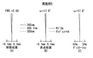
図15(A)〜(C)には、実施例1の結像レンズにおける球面収差、非点収差、およびディストーション(歪曲収差)を示す。球面収差を示す図15(A)においては、300nm,365nm,486.1nmの波長の各光線についての値を示す。非点収差を示す図15(B)においては、実線がサジタル方向の収差を示し、破線がタンジェンシャル(メリジオナル)方向の収差を示す。また、FNO.はFナンバーを示し、ωは半画角を示す。さらに、図16(A)〜(G)には、実施例1の結像レンズにおける各半画角ωでのコマ収差を示す。特に、図16(A)〜(D)はタンジェンシャル方向のコマ収差を示し、図16(E)〜(G)はサジタル方向のコマ収差を示す。図15(A)〜(C)および図16(A)〜(D)において、特に波長を明記していないものはi線に対する収差を示す。 15A to 15C show spherical aberration, astigmatism, and distortion (distortion aberration) in the imaging lens of Example 1. FIG. In FIG. 15A showing the spherical aberration, values are shown for light rays having wavelengths of 300 nm, 365 nm, and 486.1 nm. In FIG. 15B showing astigmatism, the solid line indicates the sagittal aberration, and the broken line indicates the tangential (meridional) aberration. FNO. Represents the F number, and ω represents the half angle of view. Further, FIGS. 16A to 16G show coma aberration at each half angle of view ω in the imaging lens of Example 1. FIG. 16A to 16D show coma aberration in the tangential direction, and FIGS. 16E to 16G show coma aberration in the sagittal direction. In FIGS. 15A to 15C and FIGS. 16A to 16D, those for which the wavelength is not specified indicate aberration with respect to i-line.
同様に、実施例2についての諸収差を図17(A)〜(C)および図18(A)〜(G)に示し、実施例3についての諸収差を図19(A)〜(C)および図20(A)〜(G)に示し、実施例4についての諸収差を図21(A)〜(C)および図22(A)〜(G)に示し、実施例5についての諸収差を図23(A)〜(C)および図24(A)〜(G)に示し、実施例6についての諸収差を図25(A)〜(C)および図26(A)〜(G)に示す。 Similarly, various aberrations for Example 2 are shown in FIGS. 17 (A) to (C) and FIGS. 18 (A) to (G), and various aberrations for Example 3 are shown in FIGS. 19 (A) to (C). 20A to 20G and various aberrations for Example 4 are shown in FIGS. 21A to 21C and FIGS. 22A to 22G, and various aberrations for Example 5 are shown. 23 (A) to (C) and FIGS. 24 (A) to (G), and various aberrations for Example 6 are shown in FIGS. 25 (A) to (C) and FIGS. 26 (A) to (G). Shown in
以上、各数値データおよび各収差図から明らかなように、各実施例において、35°を超える画角と、全系の焦点距離fに対して0.9倍を超える十分な長さのバックフォーカスBfとを確保しつつ、極めて良好な収差性能が発揮されている。 As can be seen from the numerical data and the aberration diagrams, in each embodiment, the angle of view exceeding 35 ° and the back focus having a sufficient length exceeding 0.9 times the focal length f of the entire system. While ensuring Bf, extremely good aberration performance is exhibited.
以上、いくつかの実施の形態および実施例を挙げて本発明を説明したが、本発明は上記実施の形態および実施例に限定されず、種々の変形が可能である。例えば、各レンズ成分の曲率半径、面間隔および屈折率の値は、上記各数値実施例で示した値に限定されず、他の値をとり得るものである。 The present invention has been described above with reference to some embodiments and examples. However, the present invention is not limited to the above embodiments and examples, and various modifications can be made. For example, the values of the radius of curvature, the surface interval, and the refractive index of each lens component are not limited to the values shown in the above numerical examples, but can take other values.
FR…前群、RE…後群、GC…平行平面板、Si…物体側から第i番目のレンズ面、Ri…物体側から第i番目のレンズ面の曲率半径、Di…物体側から第i番目と第(i+1)番目のレンズ面との面間隔、Simg…結像面(撮像面)、Z1…光軸。
FR: front group, RE: rear group, GC: plane parallel plate, Si: i-th lens surface from the object side, Ri: radius of curvature of the i-th lens surface from the object side, Di: i-th lens from the object side The distance between the first and (i + 1) th lens surfaces, Simg ... imaging surface (imaging surface), Z1 ... optical axis.
Claims (4)
物体側から順に、負の屈折力を有する前群と、正の屈折力を有する後群とからなり、
前記後群は、物体側から順に、正レンズと負レンズと正レンズとが物体側から順に配設された第1のレンズ群と、負レンズと正レンズと正レンズと負レンズとが物体側から順に配設された第2のレンズ群とからなり、
さらに、以下の条件式(1)から(4)を全て満足するように構成されている
ことを特徴とする結像レンズ。
−10<fFR/f<−0.5 ……(1)
0.5<fRE/f<2.5 ……(2)
0.5<fR1/fRE<1.5 ……(3)
−0.1<fRE/fR2<0.4 ……(4)
但し、
fFR:前群の焦点距離
f:全系の焦点距離
fRE:後群の焦点距離
fR1:第1のレンズ群の焦点距離
fR2:第2のレンズ群の焦点距離
Bf:全系のバックフォーカス An imaging lens using fluorite (CaF 2 ) and quartz (SiO 2 ) as lens materials ,
In order from the object, a front group having a negative refractive power and a rear group having positive refractive power,
The rear group includes, in order from the object side, a first lens group and a positive lens and a negative lens and a positive lens are arranged in order from the object side, a negative lens and a positive lens element and a positive lens and a negative lens and the object side A second lens group arranged in order from
Further, the imaging lens is configured to satisfy all of the following conditional expressions (1) to (4).
−10 <fFR / f <−0.5 (1)
0.5 <fRE / f <2.5 (2)
0.5 <fR1 / fRE <1.5 (3)
-0.1 <fRE / fR2 <0.4 (4)
However,
fFR: focal length of the front group f: focal length of the entire system fRE: focal length of the rear group fR1: focal length of the first lens group fR2: focal length of the second lens group Bf: back focus of the entire system
ことを特徴とする請求項1に記載の結像レンズ。
−1.0<fFR/fF1<−0.15 ……(5)
0<fF2/fFR<1 ……(6)
但し、
fF1:第3のレンズ群の焦点距離
fF2:第4のレンズ群の焦点距離 The front group includes a third lens group having a positive refractive power and a fourth lens group having a negative refractive power in order from the object side, and the following conditional expressions (5) and (6) The imaging lens according to claim 1, wherein both are configured so as to satisfy both.
−1.0 <fFR / fF1 <−0.15 (5)
0 <fF2 / fFR <1 (6)
However,
fF1: focal length of the third lens group fF2: focal length of the fourth lens group
ことを特徴とする請求項1に記載の結像レンズ。
−0.5<fFR/fF1<0.6 ……(7)
0<fF2/fFR<0.5 ……(8)
−1<fF3/fFR<0 ……(9)
但し、
fF1:第3のレンズ群の焦点距離
fF2:第4のレンズ群の焦点距離
fF3:第5のレンズ群の焦点距離 The front group includes, in order from the object side, the third lens group consisting of a single meniscus lens, a fourth lens group having a negative refractive power, a fifth lens group having a positive refractive power It becomes, and the imaging lens according to claim 1, characterized in that it is configured so as to satisfy all the (9) the following conditional expression (7).
-0.5 <fFR / fF1 <0.6 (7)
0 <fF2 / fFR <0.5 (8)
-1 <fF3 / fFR <0 (9)
However,
fF1: focal length of the third lens group fF2: focal length of the fourth lens group fF3: focal length of the fifth lens group
ことを特徴とする請求項1に記載の結像レンズ。 The imaging lens according to claim 1, wherein the front group includes two negative lenses and one positive lens in order from the object side.
Priority Applications (1)
| Application Number | Priority Date | Filing Date | Title |
|---|---|---|---|
| JP2005097379A JP4744908B2 (en) | 2005-03-30 | 2005-03-30 | Imaging lens |
Applications Claiming Priority (1)
| Application Number | Priority Date | Filing Date | Title |
|---|---|---|---|
| JP2005097379A JP4744908B2 (en) | 2005-03-30 | 2005-03-30 | Imaging lens |
Publications (2)
| Publication Number | Publication Date |
|---|---|
| JP2006276609A JP2006276609A (en) | 2006-10-12 |
| JP4744908B2 true JP4744908B2 (en) | 2011-08-10 |
Family
ID=37211420
Family Applications (1)
| Application Number | Title | Priority Date | Filing Date |
|---|---|---|---|
| JP2005097379A Expired - Fee Related JP4744908B2 (en) | 2005-03-30 | 2005-03-30 | Imaging lens |
Country Status (1)
| Country | Link |
|---|---|
| JP (1) | JP4744908B2 (en) |
Families Citing this family (5)
| Publication number | Priority date | Publication date | Assignee | Title |
|---|---|---|---|---|
| JP2008191363A (en) * | 2007-02-05 | 2008-08-21 | Tamron Co Ltd | Reading lens |
| JP5651861B2 (en) * | 2010-11-08 | 2015-01-14 | 株式会社オプトロジック | Imaging lens |
| CN110908095B (en) * | 2019-12-24 | 2023-05-26 | 协益电子(苏州)有限公司 | Small-view-field infrared monitoring and early warning lens |
| CN111929833B (en) * | 2020-09-09 | 2020-12-11 | 瑞泰光学(常州)有限公司 | Image pickup optical lens |
| CN111812821B (en) * | 2020-09-15 | 2020-11-20 | 瑞泰光学(常州)有限公司 | Image pickup optical lens |
-
2005
- 2005-03-30 JP JP2005097379A patent/JP4744908B2/en not_active Expired - Fee Related
Also Published As
| Publication number | Publication date |
|---|---|
| JP2006276609A (en) | 2006-10-12 |
Similar Documents
| Publication | Publication Date | Title |
|---|---|---|
| EP2490061B1 (en) | Imaging lens, camera and personal digital assistant | |
| JP3573575B2 (en) | Optical system | |
| JP4890090B2 (en) | Zoom lens system | |
| JP5749865B2 (en) | Imaging lens and imaging apparatus | |
| US7508601B2 (en) | Imaging lens | |
| JP5718526B2 (en) | Imaging lens and imaging apparatus | |
| JP2007279282A (en) | Imaging lens and imaging apparatus | |
| WO2011052444A1 (en) | Imaging lens | |
| JP3397439B2 (en) | Imaging lens | |
| JP2004085600A (en) | Wide-angle zoom lens system | |
| US8194329B2 (en) | Variable magnification optical system and imaging apparatus | |
| US7253972B2 (en) | Telephoto lens system | |
| JP6000842B2 (en) | Imaging optics | |
| JP4738879B2 (en) | Image reading lens and image reading apparatus | |
| JP5395495B2 (en) | Variable magnification optical system | |
| JP5506535B2 (en) | Imaging lens and inspection apparatus equipped with the imaging lens | |
| US9128271B2 (en) | Super wide angle lens and imaging apparatus using it | |
| JP4794915B2 (en) | Zoom lens and imaging apparatus having the same | |
| JP2006072188A (en) | Imaging lens | |
| JP5839357B2 (en) | Imaging lens | |
| WO2014141349A1 (en) | Wide-angle lens and imaging device | |
| JPH05341185A (en) | Objective optical system for endoscope | |
| JP4744908B2 (en) | Imaging lens | |
| JP2007052237A (en) | Imaging lens for near ultraviolet ray | |
| JP5723072B2 (en) | Wide angle lens and imaging device |
Legal Events
| Date | Code | Title | Description |
|---|---|---|---|
| A621 | Written request for application examination |
Free format text: JAPANESE INTERMEDIATE CODE: A621 Effective date: 20080324 |
|
| A711 | Notification of change in applicant |
Free format text: JAPANESE INTERMEDIATE CODE: A711 Effective date: 20100617 |
|
| A977 | Report on retrieval |
Free format text: JAPANESE INTERMEDIATE CODE: A971007 Effective date: 20110201 |
|
| A131 | Notification of reasons for refusal |
Free format text: JAPANESE INTERMEDIATE CODE: A131 Effective date: 20110208 |
|
| A521 | Written amendment |
Free format text: JAPANESE INTERMEDIATE CODE: A523 Effective date: 20110325 |
|
| A01 | Written decision to grant a patent or to grant a registration (utility model) |
Free format text: JAPANESE INTERMEDIATE CODE: A01 Effective date: 20110419 |
|
| A01 | Written decision to grant a patent or to grant a registration (utility model) |
Free format text: JAPANESE INTERMEDIATE CODE: A01 |
|
| A61 | First payment of annual fees (during grant procedure) |
Free format text: JAPANESE INTERMEDIATE CODE: A61 Effective date: 20110511 |
|
| FPAY | Renewal fee payment (event date is renewal date of database) |
Free format text: PAYMENT UNTIL: 20140520 Year of fee payment: 3 |
|
| R150 | Certificate of patent or registration of utility model |
Free format text: JAPANESE INTERMEDIATE CODE: R150 |
|
| LAPS | Cancellation because of no payment of annual fees |