JP4743235B2 - Strut suspension - Google Patents
Strut suspension Download PDFInfo
- Publication number
- JP4743235B2 JP4743235B2 JP2008192396A JP2008192396A JP4743235B2 JP 4743235 B2 JP4743235 B2 JP 4743235B2 JP 2008192396 A JP2008192396 A JP 2008192396A JP 2008192396 A JP2008192396 A JP 2008192396A JP 4743235 B2 JP4743235 B2 JP 4743235B2
- Authority
- JP
- Japan
- Prior art keywords
- vehicle
- strut
- coil
- kingpin
- spring seat
- Prior art date
- Legal status (The legal status is an assumption and is not a legal conclusion. Google has not performed a legal analysis and makes no representation as to the accuracy of the status listed.)
- Expired - Fee Related
Links
Images


Landscapes
- Vehicle Body Suspensions (AREA)
- Fluid-Damping Devices (AREA)
Description
本発明は、上端が車体に支持され、下端が車輪側部材に支持されるストラットと、上側スプリングシートと、ストラットに固定される下側スプリングシートと、上側スプリングシートと下側スプリングシートとの間にストラットを取り巻くように配置されるコイルスプリングを備えるストラット式サスペンションに関する。 The present invention provides a strut having an upper end supported by a vehicle body and a lower end supported by a wheel side member, an upper spring seat, a lower spring seat fixed to the strut, and an upper spring seat and a lower spring seat. The present invention relates to a strut suspension including a coil spring arranged to surround a strut.
従来から、コイルスプリングのコイル中心軸(軸線)とキングピン軸とが交わる通常的なストラット式サスペンションの構成に対して、コイルスプリングのコイル中心軸をキングピン軸に対してねじれ関係にする構成が知られている(例えば、特許文献1参照)。かかるサスペンション構成では、例えばキングピン軸まわりにトーイン方向のモーメントが発生するようなねじれ関係を設定することで、車両の応答性、安定性、直進性の向上を図ることが可能となる。
しかしながら、上述のような従来のストラット式サスペンションでは、標準的な車両状態、即ち舵角が中立位置にある車両停止状態においても、キングピン軸まわりにモーメントが発生した状態が形成されるので、そのモーメントに左右差があると、常時車両の走行性に悪影響がでる可能性がある。即ち、バラツキ等の影響でねじれ関係に左右差が生じた場合には、左右のキングピン軸まわりに異なるモーメントが常時発生し、車両偏向(車両流れ)の原因となるので、却って車両の安定性、直進性などが悪化する恐れがある。 However, in the conventional strut suspension as described above, a moment is generated around the kingpin axis even in a standard vehicle state, that is, a vehicle stop state in which the rudder angle is in a neutral position. If there is a difference between left and right, there is a possibility that the running performance of the vehicle will be adversely affected. In other words, when a left-right difference occurs in the torsional relationship due to the influence of variation or the like, different moments are always generated around the left and right kingpin shafts, causing vehicle deflection (vehicle flow). There is a risk that straightness will deteriorate.
そこで、本発明は、コイルスプリングのコイル中心軸とキングピン軸とがねじれ関係にある構成の長所を維持しつつ、コイルスプリングのコイル中心軸とキングピン軸とがねじれ関係にある構成の欠点である車両偏向の要因を克服することをその課題とする。 Accordingly, the present invention is a vehicle having a configuration in which the coil center axis of the coil spring and the kingpin axis are in a torsional relationship while maintaining the advantage of the configuration in which the coil center axis of the coil spring and the kingpin axis are in a torsional relationship. The challenge is to overcome the factors of deflection.
上記課題を解決するため、本発明の一局面によれば、上端が車体に支持され、下端が車輪側部材に支持されるストラットと、ベアリングを介して車体に対して回転可能に支持される上側スプリングシートと、ストラットに固定される下側スプリングシートと、上側スプリングシートと下側スプリングシートとの間にストラットを取り巻くように配置されるコイルスプリングとを備えるストラット式サスペンションであって、
舵角が中立位置にあり且つ車両が停止している車両標準状態において、
コイルスプリングのコイル中心軸とキングピン軸とが交わり、
車両背面視で、ベアリング回転軸が上側スプリングシートの座面に対して直角でない角度で傾斜し、又は、キングピン軸が下側スプリングシートの座面に対して直角でない角度で傾斜していることを特徴とする、ストラット式サスペンションが提供される。
In order to solve the above problems, according to one aspect of the present invention, a strut whose upper end is supported by a vehicle body and whose lower end is supported by a wheel-side member, and an upper side which is rotatably supported with respect to the vehicle body via a bearing. A strut-type suspension comprising a spring seat, a lower spring seat fixed to the strut, and a coil spring arranged to surround the strut between the upper spring seat and the lower spring seat,
In the vehicle standard state in which the rudder angle is in the neutral position and the vehicle is stopped,
The coil center axis of the coil spring and the kingpin axis intersect,
The bearing rotation shaft is inclined at an angle that is not perpendicular to the seat surface of the upper spring seat, or the kingpin shaft is inclined at an angle that is not perpendicular to the seat surface of the lower spring seat, as viewed from the rear of the vehicle. A featured strut suspension is provided.
上記発明において、車両背面視で、ベアリング回転軸が上側スプリングシートの座面に対して直角でない角度で傾斜し、且つ、キングピン軸が下側スプリングシートの座面に対して直角でない角度で傾斜しており、両傾斜方向が互いに逆向きであることとしてもよい。 In the above invention, the bearing rotation shaft is inclined at an angle not perpendicular to the seat surface of the upper spring seat and the kingpin shaft is inclined at an angle not perpendicular to the seat surface of the lower spring seat in the rear view of the vehicle. The two inclination directions may be opposite to each other.
また、本発明のその他の一局面によれば、舵角が中立位置にあり且つ車両が停止している車両標準状態においてコイルスプリングの反力線とキングピン軸とが交わるストラット式サスペンションにおいて、
操舵時にコイルスプリングの反力線がキングピン軸とねじれ位置になるように構成されていることを特徴とする、ストラット式サスペンションが提供される。
Further, according to another aspect of the present invention, in the strut suspension in which the reaction force line of the coil spring and the kingpin shaft intersect in a vehicle standard state where the rudder angle is in a neutral position and the vehicle is stopped,
A strut-type suspension is provided in which a reaction line of a coil spring is in a twisted position with a kingpin shaft during steering.
本発明によれば、車両偏向の要因を防止しつつ、所定の状況下でキングピン軸まわりにモーメントを発生させることができるストラット式サスペンションを得ることができる。 According to the present invention, it is possible to obtain a strut suspension that can generate a moment around a kingpin axis under a predetermined condition while preventing a factor of vehicle deflection.
以下、図面を参照して、本発明を実施するための最良の形態の説明を行う。 The best mode for carrying out the present invention will be described below with reference to the drawings.
本発明は、マクファーソンストラット式サスペンション(懸架リンクの一部として使用されるショックアブソーバと、トランスバースリンクにより構成されるサスペンション方式)に適用される。 The present invention is applied to a McPherson strut suspension (a suspension system including a shock absorber used as a part of a suspension link and a transverse link).
図1は、ストラット式サスペンションの基本構造を示す図である。アッパーサポート10は、エンジンルーム内のサスペンションタワーに設けられ、車輪を懸架するストラットアセンブリ70の上側を車体に支持する。アッパーサポート10には、ショックアブソーバ30のピストンロッド32の上端部がゴム等を介して支持されている。ショックアブソーバ30のピストンシリンダ34の下端には、サスペンションアームやナックル等を介して車輪が接続される。
FIG. 1 is a diagram showing a basic structure of a strut suspension. The
アッパーサポート10の下側には、上側のアッパスプリングシート42aがベアリング12を介して回転可能に支持され、ショックアブソーバ30のピストンシリンダ34には、下側のロアスプリングシート42bが固定される。上下のスプリングシート42a、42bの間には、ショックアブソーバ30を取り巻くようにコイルスプリング40が設けられる。コイルスプリング40は、例えば、上端径と下端径が同一であるタイプであっても、上端径と下端径が異なる所謂ビックテールタイプや中間部が膨らむ樽型タイプ等であってもよい。ショックアブソーバ30は、公知の如く、リンクの一部として上下方向の荷重を支えると共に、車輪の上下動(バウンド及びリバウンド)時にコイルスプリング40のスプリング弾性を妨げる機能をする。なお、アッパーサポート10は、コイルスプリング40の反力(スプリング力)を直接車体で受け、ショックアブソーバ30の力のみを受ける入力分離タイプである。
An
ストラットアセンブリ70は、その他の通常的な構成要素を備えるものであってよく、例えば、図1に示す例では、ショックアブソーバ30の外周部には、ダストブーツ一体式のアッパーインシュレータ37が設けられ、ショックアブソーバ30のピストンロッド32には、ピストンシリンダ34の上方向の移動を規制するバウンドストッパ38が設けられてよい。
The
上述のようなストラット式サスペンションでは、バウンド及びリバウンド時、上下のスプリングシート42a、42bは、ショックアブソーバ30の伸縮軸(=アブソーバ軸又はストラット軸、以下、「ストラット軸」という)に沿って相対的に近接及び離間することになる。また、ステアリングハンドルが操作された時、車輪がキングピン軸(KP軸)まわりに転舵されるが、この際、アッパスプリングシート42aは、ベアリング12の回転軸(=ベアリング軸)を中心として回転し、ロアスプリングシート42bは、キングピン軸を中心として回転することになる。
In the strut suspension as described above, the upper and
以下、図2以降を参照して、本発明によるストラット式サスペンションの特徴的構成を説明する。図2以下の図面では、本発明の理解を容易にするため、各構成要素は、図1に対応した参照符合を付すことで簡略化して示されている。 Hereinafter, the characteristic configuration of the strut suspension according to the present invention will be described with reference to FIG. In FIG. 2 and the subsequent drawings, in order to facilitate understanding of the present invention, each component is shown in a simplified manner with reference numerals corresponding to FIG.
[第1実施例]
図2は、本発明によるストラット式サスペンションの第1実施例を2面図で示しており、図2(A)は、右輪側を車両後方から見た背面図(図中左側が車両前側)、図2(B)は、同側面図である。
[First embodiment]
FIG. 2 shows a first embodiment of a strut suspension according to the present invention in a two-side view, and FIG. 2 (A) is a rear view of the right wheel side viewed from the rear of the vehicle (the left side in the figure is the front side of the vehicle). FIG. 2B is a side view of the same.
本実施例のストラット式サスペンションは、図2に示すように、コイルスプリング40のコイル中心軸とキングピン軸とが交わり、且つ、コイルスプリング40のコイル中心軸とストラット軸とが車両側面視でゼロより大きな角度θ1をなしている。
As shown in FIG. 2, the strut type suspension of the present embodiment intersects the coil center axis of the
即ち、コイルスプリング40のコイル中心軸とキングピン軸とは、図2(A)の背面図及び図2(B)の側面図で、同一の高さに交点を有している。また、コイルスプリング40のコイル中心軸は、車両側面視で、ストラット軸に対して角度θ1だけ傾斜している。尚、図2に示す実施例では、ストラット軸とキングピン軸が車両側面視で一致しているが、必ずしも一致している必要はない。
That is, the coil center axis and the kingpin axis of the
尚、添付の特許請求の範囲及び本明細書において、各軸の関係は、特に明示しない限り、車両標準状態、即ち舵角が中立にあり且つ車両が停止している状態における関係である。従って、本実施例のストラット式サスペンションでは、車両標準状態において、コイル中心軸とキングピン軸とが(一点で)交わる関係にあるので、コイル中心軸とキングピン軸とねじれ関係にある構成とは対照的に、車両標準状態においてキングピン軸まわりにモーメントが発生することはない。 In the appended claims and the present specification, unless otherwise specified, the relationship between the axes is a vehicle standard state, that is, a relationship in a state where the steering angle is neutral and the vehicle is stopped. Therefore, in the strut type suspension of the present embodiment, the coil center axis and the kingpin axis intersect (at one point) in the vehicle standard state, which is in contrast to the configuration in which the coil center axis and the kingpin axis are twisted. In addition, no moment is generated around the kingpin axis in the vehicle standard state.
ところで、一般的なストラット式サスペンションでは、コイル中心軸がストラット軸に平行に設定されるので、コイルスプリング40の伸縮時においてもコイルスプリング40が発生する反力線はコイル中心軸に一致した状態を維持する。従って、かかる一般的なストラット式サスペンションでは、バウンド/リバウンド時にコイル反力線とキングピン軸との関係が変化することはなく、それ故に、常時、キングピン軸まわりにモーメントが発生することはない。
By the way, in a general strut suspension, the coil central axis is set parallel to the strut axis, so that the reaction force line generated by the
これに対して、本実施例のストラット式サスペンションは、車両標準状態では、上述の如く、コイル反力線がキングピン軸と交わるので、キングピン軸まわりにモーメントが発生しない。一方、車両側面視でコイルスプリング40のコイル中心軸がストラット軸に対して傾斜しているので、バウンド/リバウンド時には、コイル反力線とキングピン軸との関係が変化し、コイル反力線とキングピン軸とねじれ関係になる。
On the other hand, in the strut type suspension of this embodiment, in the vehicle standard state, the coil reaction force line intersects with the kingpin axis as described above, so that no moment is generated around the kingpin axis. On the other hand, since the coil central axis of the
従って、本実施例によれば、車両標準状態では、キングピン軸まわりにモーメントが発生しない状態が形成されるので、車両の偏向の原因となるモーメントの左右差が発生するのを防止することができる。一方、バウンド/リバウンド状態では、キングピン軸まわりにモーメントが発生した状態が形成されるので、当該モーメントの作用により車両の走行性能を高めることができる。以下、この原理を詳説する。 Therefore, according to the present embodiment, in the vehicle standard state, a state in which no moment is generated around the kingpin axis is formed, so that it is possible to prevent the occurrence of a left-right difference in moment that causes the vehicle to deflect. . On the other hand, in the bound / rebound state, a state in which a moment is generated around the kingpin axis is formed, so that the running performance of the vehicle can be enhanced by the action of the moment. Hereinafter, this principle will be described in detail.
図3(B)には、図3(A)に示す標準状態に対して、上下のスプリングシート42a、42bが同方向に角度変化した状態でのコイル反力線が示される。
FIG. 3B shows coil reaction force lines in a state where the upper and
図3(B)に示すように、上下のスプリングシート42a、42bが同方向に角度変化すると、コイル反力線(実線)は、見かけ上の中心線(点線)に対して、反力が大きい側、即ち上下のスプリングシート42a、42b間の距離(中心線に沿った距離)が小さい側に移動する。即ち、コイル反力線は、見かけ上の中心線に対して、スプリングシート42a、42bの角度変化方向と同一方向に傾斜する。本実施例はこの原理に着目している。
As shown in FIG. 3B, when the upper and
本実施例では、図4(A)(図2(B)に対応する右輪に対する側面視)に示すように、バウンド時には、ロアスプリングシート42b(標準時を2点鎖線で図示)がストラット軸に沿って上側に移動し、見かけ上の中心線(点線)が、コイル中心軸(標準状態)に対して傾斜する。即ち、上下のスプリングシート42a、42bの関係が図3(B)に示す状態になる。従って、コイル反力線(実線)は、見かけ上の中心線(点線)に対して反力が大きい側に画成される。即ち、本例では、図4(A)に示すように、コイル中心軸がストラット軸に対して車両上側が車両後側に倒れる方向(反時計方向)に傾斜しているので、バウンド時のコイル反力線は、キングピン軸よりも車両前側にオフセットする。この場合、バウンド時にキングピン軸まわりにトーイン方向にモーメントが発生した状態が形成される。
In this embodiment, as shown in FIG. 4 (A) (side view with respect to the right wheel corresponding to FIG. 2 (B)), the
同様に、リバウンド時には、図4(B)に示すように、ロアスプリングシート42b(標準時を2点鎖線で図示)がストラット軸に沿って下側に移動し、見かけ上の中心線(点線)が、コイル中心軸(標準状態)に対して傾斜する。但し、この場合、中心線はバウンド時とは逆側に傾斜するので、上下のスプリングシート42a、42bの関係が図3(B)に示す状態とは逆に傾いた状態になる。従って、同様に、コイル反力線(実線)は、見かけ上の中心線(点線)に対して反力が大きい側に画成される。即ち、本例では、図4(B)に示すように、車両側面視でコイル中心軸がストラット軸に対して反時計方向に角度θ1だけ傾斜しているので、リバウンド時のコイル反力線は、キングピン軸よりも車両後側にオフセットする。この場合、リバウンド時にキングピン軸まわりにトーアウト方向にモーメントが発生した状態が形成される。
Similarly, when rebounding, as shown in FIG. 4B, the
このように本実施例によれば、バウンド/リバウンド時にのみキングピン軸まわりに所望のモーメントを発生させることができるので、通常的な直進走行における車両の偏向の原因となるモーメントの左右差の問題が無くなる。また、本実施例では、車両側面視でコイル中心軸をストラット軸(キングピン軸)に対して反時計方向に傾斜させることで、リバウンド時にトーアウト方向のモーメントを、バウンド時にトーイン方向のモーメントをキングピン軸まわりに発生させている。これにより、例えば操舵時、車両のロールが発生し、サスペンションがストロークする状態において、キングピン軸まわりに減衰モーメントとして作用するモーメントを発生させることができる。これにより、キングピン軸まわりの減衰効果が得られ、車両の走行性として高速操舵時の安定性が向上する。 Thus, according to the present embodiment, a desired moment can be generated around the kingpin axis only at the time of bounce / rebound, so there is a problem of the left-right difference in the moment that causes the deflection of the vehicle in normal straight traveling. Disappear. In this embodiment, the coil central axis is tilted counterclockwise with respect to the strut axis (kingpin axis) when viewed from the side of the vehicle, so that the moment in the toe-out direction during rebounding and the moment in the toe-in direction during bouncing It is generated around. As a result, for example, when the vehicle rolls and the suspension strokes during steering, a moment that acts as a damping moment around the kingpin axis can be generated. Thereby, the damping effect around the kingpin axis is obtained, and the stability during high-speed steering is improved as the running performance of the vehicle.
但し、減衰モーメントの作用よる高速操舵時の安定性よりも、アンダステア特性や低速操舵時の安定性などが重視される場合、車両側面視でコイル中心軸をストラット軸(キングピン軸)に対して逆向きに傾斜させることで、即ち車両側面視でコイル中心軸をストラット軸に対して車両上側が車両前側に倒れる方向(時計方向)に角度θ1だけ傾斜させることで、リバウンド時にトーイン方向のモーメントを、バウンド時にトーアウト方向のモーメントをキングピン軸まわりに発生させるようにしてもよい。 However, when the understeer characteristics and the stability at low speed steering are more important than the stability at high speed steering due to the action of the damping moment, the coil center axis is reversed from the strut axis (kingpin axis) in the vehicle side view. By tilting in the direction, that is, by tilting the coil central axis by the angle θ1 in the direction in which the upper side of the vehicle falls to the front side of the vehicle (clockwise) with respect to the strut axis in a side view of the vehicle, A moment in the toe-out direction may be generated around the kingpin axis when bounding.
[第2実施例]
図5は、本発明によるストラット式サスペンションの第1実施例を2面図で示しており、図5(A)は、右輪側を車両後方から見た背面図(図中左側が車両前側)、図5(B)は、同側面図である。
[Second embodiment]
FIG. 5 shows a first embodiment of a strut suspension according to the present invention in a two-side view, and FIG. 5 (A) is a rear view of the right wheel side viewed from the rear of the vehicle (the left side in the figure is the front side of the vehicle). FIG. 5B is a side view of the same.
本実施例のストラット式サスペンションは、図5に示すように、車両標準状態で、コイル中心軸とキングピン軸とが交わる関係にある。従って、上記の第1実施例と同様、車両標準状態で、キングピン軸まわりにモーメントが発生することがないので、通常的な直進走行における車両の偏向の原因となるようなモーメントの左右差の問題が無くなる。 As shown in FIG. 5, the strut suspension of the present embodiment is in a vehicle standard state where the coil center axis and the kingpin axis intersect. Therefore, as in the first embodiment, no moment is generated around the kingpin axis in the standard vehicle state. Therefore, there is a problem of the right / left difference of the moment that causes the deflection of the vehicle in normal straight traveling. Disappears.
また、本実施例のストラット式サスペンションは、車両背面視で、ベアリング回転軸がアッパスプリングシート42aの座面に対して直角でない角度θ2で傾斜し、且つ、キングピン軸がロアスプリングシート42bの座面に対して直角でない角度θ3で傾斜しており、それらの両傾斜方向が互いに逆向きである。換言すると、本実施例のストラット式サスペンションは、車両背面視で、アッパスプリングシート42a側のコイルスプリング40の座面がベアリング回転軸に対して直角でない角度θ2で傾斜し、ロアスプリングシート42b側のコイルスプリング40の座面がキングピン軸に対して直角でない角度θ3で傾斜しており、それらの両傾斜方向が互いに逆向きである。尚、図5に示す実施例では、キングピン軸とベアリング回転軸が一致しているが、必ずしも一致している必要はない。
In addition, the strut suspension of the present embodiment has a bearing rotation shaft inclined at an angle θ2 that is not perpendicular to the seating surface of the
ところで、一般的なストラット式サスペンションでは、ベアリング回転軸がアッパスプリングシート42aの座面に対して直角に設定され、且つ、キングピン軸がロアスプリングシート42bの座面に対して直角に設定されるので、操舵時においてもコイルスプリング40が発生する反力線はコイル中心軸に一致した状態を維持する。従って、かかる一般的なストラット式サスペンションでは、操舵時にコイル反力線とキングピン軸との関係が変化することはなく、それ故に、常時、キングピン軸まわりにモーメントが発生することはない。
By the way, in a general strut suspension, the bearing rotation axis is set at a right angle to the seating surface of the
これに対して、本実施例のストラット式サスペンションは、車両標準状態では、上述の如く、コイル反力線がキングピン軸と交わるので、キングピン軸まわりにモーメントが発生しない。一方、上下のスプリングシート42a、42bが上述のような座面傾斜を有しているので、操舵時には、コイル反力線とキングピン軸との関係が変化し、コイル反力線とキングピン軸とねじれ関係になる。従って、本実施例によれば、操舵状態では、キングピン軸まわりにモーメントが発生した状態が形成されるので、当該モーメントの作用により車両の走行性能を高めることができる。以下、この原理を詳説する。
On the other hand, in the strut type suspension of this embodiment, in the vehicle standard state, the coil reaction force line intersects with the kingpin axis as described above, so that no moment is generated around the kingpin axis. On the other hand, since the upper and
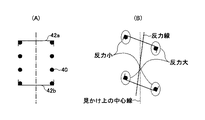
図6(B)には、図6(A)に示す標準状態に対して、上下のスプリングシート42a、42bが同方向に角度変化した状態でのコイル反力線が示される。
FIG. 6B shows coil reaction force lines in a state where the upper and
図6(B)に示すように、上下のスプリングシート42a、42bが逆方向に角度変化すると、コイル反力線(実線)は、見かけ上の中心線(点線)に対して、反力が大きい側、即ち上下のスプリングシート42a、42b間の距離(中心線に沿った距離)が小さい側に移動する。即ち、コイル反力線は、見かけ上の中心線に対して、スプリングシート42a、42bが近接する側にオフセットする。本実施例はこの原理に着目している。
As shown in FIG. 6B, when the upper and
具体的には、本実施例では、図7(A)(図5(B)に対応する右輪に対する側面視)に示すように、左切り操舵時には、上下のスプリングシート42a、42bが互いに車両前側で近接するように角度変化し、コイル反力線(実線)が、キングピン軸よりも車両前側にオフセットする。これにより、キングピン軸まわりにトーイン方向にモーメントが発生した状態が形成される。
Specifically, in this embodiment, as shown in FIG. 7A (side view with respect to the right wheel corresponding to FIG. 5B), the upper and
一方、図7(B)に示すように、右切り操舵時には、上下のスプリングシート42a、42b(標準時を2点鎖線で図示)が互いに車両後側で近接するように角度変化し、コイル反力線(実線)が、キングピン軸よりも車両後側にオフセットする。キングピン軸まわりにトーアウト方向にモーメントが発生した状態が形成される。
On the other hand, as shown in FIG. 7B, during right turn steering, the angle changes so that the upper and
このように本実施例によれば、左切り/右切り操舵時にのみキングピン軸まわりに所望のモーメントを発生させることができるので、通常的な直進走行における車両の偏向の原因となるモーメントの左右差の問題が無くなる。また、本実施例では、車両背面視でアッパスプリングシート42aの座面をベアリング回転軸に対して時計方向に傾斜させ、且つ、車両背面視でロアスプリングシート42bの座面をキングピン軸に対して反時計方向に傾斜させることで、右切り操舵時にトーアウト方向のモーメントを、左切り操舵時にトーイン方向のモーメントをキングピン軸まわりに発生させている。これにより、操舵時に、キングピン軸まわりに減衰モーメントとして作用するモーメントを発生させることができる。これにより、キングピン軸まわりの減衰効果が得られ、車両の走行性として高速操舵時の安定性が向上する。
As described above, according to the present embodiment, a desired moment can be generated around the kingpin axis only at the time of left turn / right turn steering. Therefore, the left-right difference of the moment causing the deflection of the vehicle in normal straight traveling The problem of disappears. Further, in the present embodiment, the seat surface of the
但し、減衰モーメントの作用よる高速操舵時の安定性よりも、車両背面視でアッパスプリングシート42aの座面をベアリング回転軸に対して反時計方向に傾斜させ、且つ、車両背面視でロアスプリングシート42bの座面をキングピン軸に対して時計方向に傾斜させることで、右切り操舵時にトーイン方向のモーメントを、左切り操舵時にトーアウト方向のモーメントをキングピン軸まわりに発生させるようにしてもよい。
However, the seating surface of the
以上、本発明の好ましい実施例について詳説したが、本発明は、上述した実施例に制限されることはなく、本発明の範囲を逸脱することなく、上述した実施例に種々の変形及び置換を加えることができる。 The preferred embodiments of the present invention have been described in detail above. However, the present invention is not limited to the above-described embodiments, and various modifications and substitutions can be made to the above-described embodiments without departing from the scope of the present invention. Can be added.
例えば、上述の第2実施例では、車両背面視でアッパスプリングシート42aの座面をベアリング回転軸に対して時計方向に傾斜させ、且つ、車両背面視でロアスプリングシート42bの座面をキングピン軸に対して反時計方向に傾斜させるものであったが、車両背面視でアッパスプリングシート42aの座面をベアリング回転軸に対して時計方向に傾斜させ、又は、車両背面視でロアスプリングシート42bの座面をキングピン軸に対して反時計方向に傾斜させるものであってもよい。
For example, in the second embodiment described above, the seat surface of the
例えば、図8には、車両背面視でアッパスプリングシート42aの座面をベアリング回転軸に対して時計方向に傾斜させ、車両背面視でアッパスプリングシート42aの座面をキングピン軸に直角(θ3=90°)に設定した変形例が示されている。
For example, FIG. 8 shows that the seat surface of the
本変形例では、図9(A)(図5(B)に対応する右輪に対する側面視)に示すように、左切り操舵時には、アッパスプリングシート42aがロアスプリングシート42b(角度変化なし)に対して車両前側で近接するように角度変化する。このとき、コイル反力線(実線)が、図3で説明した原理に従って、ロアスプリングシート42b側を起点にキングピン軸に対して車両前側に傾斜するので、コイル反力線とキングピン軸とがねじれ関係となる。従って、この変形例においても、左切り操舵時に、キングピン軸まわりにトーイン方向にモーメントが発生した状態が形成されるので、モーメントアーム長を十分確保できる限り、同様の効果を得ることができる。
In this modification, as shown in FIG. 9A (side view with respect to the right wheel corresponding to FIG. 5B), the
同様に、図9(B)に示すように、右切り操舵時には、アッパスプリングシート42aがロアスプリングシート42b(角度変化なし)に対して車両後側で近接するように角度変化する。このとき、コイル反力線(実線)が、図3で説明した原理に従って、ロアスプリングシート42b側を起点にキングピン軸に対して車両後側に傾斜するので、コイル反力線とキングピン軸とがねじれ関係となる。従って、この変形例においても、右切り操舵時に、キングピン軸まわりにトーアウト方向にモーメントが発生した状態が形成されるので、モーメントアーム長を十分確保できる限り、同様の効果を得ることができる。
Similarly, as shown in FIG. 9B, during right turn steering, the angle changes so that the
本変形例と同様の観点から、車両背面視でロアスプリングシート42bの座面側のみをキングピン軸に対して反時計方向に傾斜させてもよいし、双方を同一方向に傾斜させるが傾斜度合いを異ならせることで操舵時にねじれ関係を形成させることとしてもよい。
From the same viewpoint as this modification, only the seat surface side of the
以上の説明において、第1実施例は、本発明の含まれない参考例として開示されている。 In the above description, the first embodiment is disclosed as a reference example not including the present invention.
10 アッパーサポート
12 ベアリング
30 ショックアブソーバ
32 ピストンロッド
34 ピストンシリンダ
40 コイルスプリング
42a アッパスプリングシート
42b ロアスプリングシート
10
Claims (5)
舵角が中立位置にあり且つ車両が停止している車両標準状態において、
コイルスプリングのコイル中心軸とキングピン軸とが交わり、
車両背面視で、ベアリング回転軸が上側スプリングシートの座面に対して直角でない角度で傾斜し、又は、キングピン軸が下側スプリングシートの座面に対して直角でない角度で傾斜していることを特徴とする、ストラット式サスペンション。 A strut whose upper end is supported by the vehicle body and whose lower end is supported by the wheel side member, an upper spring seat which is rotatably supported by the vehicle body via a bearing, a lower spring seat which is fixed to the strut, and an upper side A strut suspension comprising a coil spring arranged to surround the strut between a spring seat and a lower spring seat,
In the vehicle standard state in which the rudder angle is in the neutral position and the vehicle is stopped,
The coil center axis of the coil spring and the kingpin axis intersect,
The bearing rotation shaft is inclined at an angle that is not perpendicular to the seat surface of the upper spring seat, or the kingpin shaft is inclined at an angle that is not perpendicular to the seat surface of the lower spring seat, as viewed from the rear of the vehicle. A strut suspension.
操舵時にコイルスプリングの反力線がキングピン軸とねじれ位置になるように構成されていることを特徴とする、ストラット式サスペンション。 In a strut type suspension in which the reaction line of the coil spring and the kingpin shaft intersect in a vehicle standard state where the rudder angle is in a neutral position and the vehicle is stopped,
A strut-type suspension characterized in that the reaction force line of the coil spring is in a twisted position with the kingpin shaft during steering.
Priority Applications (1)
| Application Number | Priority Date | Filing Date | Title |
|---|---|---|---|
| JP2008192396A JP4743235B2 (en) | 2008-07-25 | 2008-07-25 | Strut suspension |
Applications Claiming Priority (1)
| Application Number | Priority Date | Filing Date | Title |
|---|---|---|---|
| JP2008192396A JP4743235B2 (en) | 2008-07-25 | 2008-07-25 | Strut suspension |
Related Parent Applications (1)
| Application Number | Title | Priority Date | Filing Date |
|---|---|---|---|
| JP2004279346A Division JP2006088962A (en) | 2004-09-27 | 2004-09-27 | Strut suspension |
Publications (2)
| Publication Number | Publication Date |
|---|---|
| JP2008265758A JP2008265758A (en) | 2008-11-06 |
| JP4743235B2 true JP4743235B2 (en) | 2011-08-10 |
Family
ID=40045825
Family Applications (1)
| Application Number | Title | Priority Date | Filing Date |
|---|---|---|---|
| JP2008192396A Expired - Fee Related JP4743235B2 (en) | 2008-07-25 | 2008-07-25 | Strut suspension |
Country Status (1)
| Country | Link |
|---|---|
| JP (1) | JP4743235B2 (en) |
Family Cites Families (2)
| Publication number | Priority date | Publication date | Assignee | Title |
|---|---|---|---|---|
| JP3550908B2 (en) * | 1996-10-04 | 2004-08-04 | 日産自動車株式会社 | Front suspension device |
| JP4162804B2 (en) * | 1998-07-31 | 2008-10-08 | 中央発條株式会社 | Strut type suspension system |
-
2008
- 2008-07-25 JP JP2008192396A patent/JP4743235B2/en not_active Expired - Fee Related
Also Published As
| Publication number | Publication date |
|---|---|
| JP2008265758A (en) | 2008-11-06 |
Similar Documents
| Publication | Publication Date | Title |
|---|---|---|
| US8398092B2 (en) | Active roll control system for vehicle | |
| JP2008018924A (en) | Suspension device | |
| WO2018092587A1 (en) | Suspension device for vehicles | |
| JP2006088962A (en) | Strut suspension | |
| KR101461916B1 (en) | Coupled torsion beam axle type suspension system | |
| JP2004276736A (en) | Front suspension device of automobile | |
| JP4254599B2 (en) | Strut suspension | |
| JP2002362123A (en) | Front suspension structure | |
| JP2009227004A (en) | Suspension device | |
| JP5217963B2 (en) | Front suspension device | |
| JP4743235B2 (en) | Strut suspension | |
| JP4792316B2 (en) | Strut suspension system for vehicles | |
| JP4370518B2 (en) | Front suspension device for automobile | |
| JP4701947B2 (en) | Strut suspension for steering wheels | |
| JP2003112511A (en) | Front suspension device | |
| JP2003136928A (en) | Vehicular suspension device | |
| JP4647279B2 (en) | Rear suspension | |
| JP2003146038A (en) | Suspension device | |
| JP2003118339A (en) | Suspension device for vehicle | |
| JP4236523B2 (en) | suspension | |
| JP2007331403A (en) | Suspension device | |
| JP2006182287A (en) | Front suspension device | |
| JP2003118345A (en) | Strut type suspension device | |
| JP4704138B2 (en) | Vehicle suspension | |
| JP2008114696A (en) | Stabilizer connection structure |
Legal Events
| Date | Code | Title | Description |
|---|---|---|---|
| A131 | Notification of reasons for refusal |
Free format text: JAPANESE INTERMEDIATE CODE: A131 Effective date: 20100817 |
|
| A977 | Report on retrieval |
Free format text: JAPANESE INTERMEDIATE CODE: A971007 Effective date: 20100819 |
|
| A521 | Written amendment |
Free format text: JAPANESE INTERMEDIATE CODE: A523 Effective date: 20101014 |
|
| A01 | Written decision to grant a patent or to grant a registration (utility model) |
Free format text: JAPANESE INTERMEDIATE CODE: A01 Effective date: 20110412 |
|
| A61 | First payment of annual fees (during grant procedure) |
Free format text: JAPANESE INTERMEDIATE CODE: A61 Effective date: 20110425 |
|
| FPAY | Renewal fee payment (prs date is renewal date of database) |
Free format text: PAYMENT UNTIL: 20140520 Year of fee payment: 3 |
|
| FPAY | Renewal fee payment (prs date is renewal date of database) |
Free format text: PAYMENT UNTIL: 20140520 Year of fee payment: 3 |
|
| LAPS | Cancellation because of no payment of annual fees |