JP4729801B2 - Vibrator driving device and angular velocity sensor provided with the vibrator driving device - Google Patents
Vibrator driving device and angular velocity sensor provided with the vibrator driving device Download PDFInfo
- Publication number
- JP4729801B2 JP4729801B2 JP2001076275A JP2001076275A JP4729801B2 JP 4729801 B2 JP4729801 B2 JP 4729801B2 JP 2001076275 A JP2001076275 A JP 2001076275A JP 2001076275 A JP2001076275 A JP 2001076275A JP 4729801 B2 JP4729801 B2 JP 4729801B2
- Authority
- JP
- Japan
- Prior art keywords
- drive
- voltage component
- amplitude
- vibrator
- signal
- Prior art date
- Legal status (The legal status is an assumption and is not a legal conclusion. Google has not performed a legal analysis and makes no representation as to the accuracy of the status listed.)
- Expired - Fee Related
Links
Images


Classifications
-
- G—PHYSICS
- G01—MEASURING; TESTING
- G01C—MEASURING DISTANCES, LEVELS OR BEARINGS; SURVEYING; NAVIGATION; GYROSCOPIC INSTRUMENTS; PHOTOGRAMMETRY OR VIDEOGRAMMETRY
- G01C19/00—Gyroscopes; Turn-sensitive devices using vibrating masses; Turn-sensitive devices without moving masses; Measuring angular rate using gyroscopic effects
- G01C19/56—Turn-sensitive devices using vibrating masses, e.g. vibratory angular rate sensors based on Coriolis forces
- G01C19/5719—Turn-sensitive devices using vibrating masses, e.g. vibratory angular rate sensors based on Coriolis forces using planar vibrating masses driven in a translation vibration along an axis
Landscapes
- Physics & Mathematics (AREA)
- Engineering & Computer Science (AREA)
- General Physics & Mathematics (AREA)
- Radar, Positioning & Navigation (AREA)
- Remote Sensing (AREA)
- Gyroscopes (AREA)
- Micromachines (AREA)
Description
【0001】
【発明の属する技術分野】
本発明は、例えば角速度センサが備える静電駆動型の振動子を振動駆動する振動子駆動装置及び振動子駆動装置を備えた角速度センサに関するものである。
【0002】
【従来の技術】
従来、例えば角速度センサが備える静電駆動型の振動子を振動駆動する振動子駆動装置としては、例えば図19のブロック図にて表されるものが知られている。同図に示されるように、静電駆動型振動子の駆動方向の振動による変位は、駆動方向変位検出電極81から変位信号として変位信号検出部82に出力される。
【0003】
変位信号検出部82に出力された変位信号は、同期検波回路83において駆動方向の変位に同期したタイミングにて同期検波されて振動振幅情報として振幅調節器84に出力され、また、同時に90deg移相器85を介して略90度移相されて同振幅調節器84に出力される。なお、変位信号を90deg移相器85を介して略90度移相するのは、上記振幅調節器84において同変位信号に対して略90度の位相差を有する駆動信号の交流電圧成分を生成し、静電駆動型振動子を発振しやすくするためである。
【0004】
上記振幅調節器84に出力された振動振幅情報は、同振幅調節器84において振幅設定値と比較される。そして、上記振動振幅情報が小さいときには、増加調節された振幅を有する駆動信号の交流電圧成分が生成され、一方、同振動振幅情報が大きいときには、低減調節された振幅を有する駆動信号の交流電圧成分が生成される。このような駆動信号の交流電圧成分の振幅調節は、上記振動子の駆動方向の振動振幅が一定になるように同振動子の振動駆動力を制御するためである。このように振幅調節された駆動信号の交流電圧成分は、加算器86に出力される。
【0005】
上記加算器86において、上記振幅調節された駆動信号の交流電圧成分と所定値を有する駆動信号の直流電圧成分(バイアス電圧)とが加算されて駆動信号が生成される。そして、このように生成された駆動信号が駆動電極87に印加される。この駆動信号(印加電圧)の2乗に比例して上記振動子との間で発生する静電引力(振動駆動力)の振動により、同振動子は駆動方向の振動振幅が一定になるように振動駆動される。
【0006】
【発明が解決しようとする課題】
ところで、上記駆動信号の交流電圧成分は変位信号と同等の周波数であるため、同駆動信号の交流電圧成分は同変位信号のノイズ源となっている。すなわち、この駆動信号の交流電圧成分は、静電駆動型振動子の振動状態の検出誤差の原因となる。また、例えば上記駆動装置を振動型角速度センサに適用しこの静電駆動型振動子が振動駆動されている状態において、角速度の検出をする場合には、その検出出力のずれの原因となる。このような振動状態の検出誤差や角速度の検出出力のずれは、固有の値を有するのであれば、その補正は容易である。
【0007】
しかし、静電駆動型振動子の経時変化や環境温度の変化などによって同静電駆動型振動子の駆動方向のQ値が変動した場合に、同振動子の駆動方向の振動振幅が一定になるように上述のように駆動信号の交流電圧成分が増減調節されると、同変位信号に混入するノイズ量が変動することとなる。従って、静電駆動型振動子の振動状態の検出誤差や角速度の検出出力のずれが変動することとなる。
【0008】
そこで、このような静電駆動型振動子の振動状態の検出誤差や角速度の検出出力のずれの変動を抑制するために、駆動信号の交流電圧成分の振幅を一定とし、直流電圧成分(バイアス電圧)のみを増減調節して、上記振動子の駆動方向の振動振幅が一定になるように同振動子の振動駆動力を制御することが出願人らによって提案されている。
【0009】
すなわち、図20のブロック図に示されるように、静電駆動型振動子の駆動方向の振動による変位は、駆動方向変位検出電極91から変位信号として変位信号検出部92に出力される。
【0010】
変位信号検出部92に出力された変位信号は、同期検波回路93において駆動方向の変位に同期したタイミングにて同期検波されて振動振幅情報として振幅調節器94に出力される。上記振幅調節器94に出力された振動振幅情報は、同振幅調節器94において振幅設定値と比較される。そして、上記振動振幅情報が小さいときには、増加調節された駆動信号の直流電圧成分(バイアス電圧)が生成され、一方、同振動振幅情報が大きいときには、低減調節された駆動信号の直流電圧成分(バイアス電圧)が生成される。このような駆動信号の直流電圧成分の調節は、静電駆動型振動子の駆動方向の振動振幅が一定になるように同振動子の振動駆動力を制御するためである。このように生成された駆動信号の直流電圧成分は、加算器95に出力される。
【0011】
一方、上記変位信号検出部92に出力された変位信号は、同時に90deg移相器96を介して略90度移相されて交流電圧成分生成部97に出力される。そして、上記交流電圧成分生成部97において、上記変位信号と同等の周波数を有して同変位信号に対して略90度移相され、一定の振幅を有する駆動信号の交流電圧成分が生成される。この駆動信号の交流電圧成分の振幅は、上記振動子を共振周波数にて発振させるのに十分な大きさとなっている。なお、上記駆動信号の交流電圧成分を変位信号に対して略90度移相するのは、上記振動子を最も効率のよい共振点にて駆動し、発振しやすくするためである。このように生成された駆動信号の交流電圧成分は、上記加算器95に出力される。
【0012】
上記加算器95において、上記調節された駆動信号の直流電圧成分と一定の振幅を有する駆動信号の交流電圧成分とが加算されて駆動信号が生成される。そして、このように生成された駆動信号が駆動電極98に印加される。この駆動信号(印加電圧)の2乗に比例して上記振動子との間で発生する静電引力(振動駆動力)の振動により、同振動子は駆動方向の振動振幅が一定になるように振動駆動される。
【0013】
このような振動子駆動装置においては、駆動信号の交流電圧成分に基づき変位信号に混入するノイズ量を低減するために、同駆動信号の交流電圧成分は比較的小さな振幅となるように設定されている。しかし、駆動信号の直流電圧成分のみの増減調節により振動子の振動駆動力を制御する場合、同直流電圧成分(バイアス電圧)の調節範囲が電源電圧の能力によって制約を受けるために、同振動子の定常時の振動駆動力に対して起動時の振動駆動力(最大駆動力)を十分に得ることができない。従って、上記振動子を所要の振動状態にするまでの立ち上げに時間がかかることがある。この傾向は、特にQ値の高い振動子ほど顕著となる。
【0014】
本発明の目的は、静電駆動型振動子の振動状態の検出誤差等の変動を抑制し、且つ、同振動子の起動時の振動振幅の立ち上げ時間を短縮することができる振動子駆動装置及び振動子駆動装置を備えた角速度センサを提供することにある。
【0015】
【課題を解決するための手段】
上記問題点を解決するために、請求項1に記載の発明は、静電駆動型振動子に駆動信号を出力して該静電駆動型振動子を振動駆動する駆動手段と、該静電駆動型振動子の振動による変位を変位信号として検出する検出手段と、該検出された変位信号に基づき該駆動手段から出力される駆動信号を生成制御する振幅調節手段とを備えた振動子駆動装置において、前記振幅調節手段は、定常時において一定の第1の振幅を有する前記駆動信号の交流電圧成分を生成し、起動時において該第1の振幅よりも大きい第2の振幅を有する該駆動信号の交流電圧成分を生成する交流電圧成分生成手段と、前記検出された変位信号に基づき増減制御される該駆動信号の直流電圧成分を生成する直流電圧成分生成手段とを有し、定常時において、前記生成された一定の第1の振幅を有する交流電圧成分及び直流電圧成分からなる駆動信号に基づき、前記静電駆動型振動子の振動駆動力を制御して、該静電駆動型振動子の振動振幅が一定になるように調節を行い、起動時において、前記生成された第2の振幅を有する交流電圧成分及び直流電圧成分からなる駆動信号に基づき、前記静電駆動型振動子に対してより大きな振動駆動力を印加して該静電駆動型振動子の振動振幅を増大することを要旨とする。
【0016】
請求項2に記載の発明は、請求項1に記載の振動子駆動装置において、前記交流電圧成分生成手段は、所定振幅の交流電圧成分を生成する交流電圧成分生成部と、定常時と起動時とに応じて該所定振幅の交流電圧成分を異なる増幅率にて増幅して前記第1の振幅を有する駆動信号の交流電圧成分及び前記第2の振幅を有する駆動信号の交流電圧成分を生成する増幅部とを備えることを要旨とする。
【0017】
請求項3に記載の発明は、請求項1に記載の振動子駆動装置において、前記交流電圧成分生成手段は、前記第1の振幅を有する駆動信号の交流電圧成分を生成する第1の信号経路と、前記第2の振幅を有する駆動動信号の交流電圧成分を生成する第2の信号経路と、定常時と起動時とに応じて該第1の信号経路と第2の信号経路との切り替えを行う切り替え部とを備えることを要旨とする。
【0018】
請求項4に記載の発明は、静電駆動型振動子に駆動信号を出力して該静電駆動型振動子を振動駆動する駆動手段と、該静電駆動型振動子の振動による変位を変位信号として検出する検出手段と、該検出された変位信号に基づき該駆動手段から出力される駆動信号を生成制御する振幅調節手段とを備えた振動子駆動装置において、前記振幅調節手段は、定常時において第1の増幅率にて前記変位信号を移相増幅して一定の振幅を有する前記駆動信号の交流電圧成分を生成し、起動時において該第1の増幅率よりも大きい第2の増幅率にて該変位信号を移相増幅して該駆動信号の交流電圧成分を生成する交流電圧成分生成手段と、前記検出された変位信号に基づき増減制御される該駆動信号の直流電圧成分を生成する直流電圧成分生成手段とを有し、定常時において、前記第1の増幅率にて増幅生成された一定の振幅を有する交流電圧成分及び直流電圧成分からなる駆動信号に基づき、前記静電駆動型振動子の振動駆動力を制御して、該静電駆動型振動子の振動振幅が一定になるように調節を行い、起動時において、前記第2の増幅率にて増幅生成された交流電圧成分及び直流電圧成分からなる駆動信号に基づき、前記静電駆動型振動子に対してより大きな振動駆動力を印加して該静電駆動型振動子の振動振幅を増大することを要旨とする。
【0019】
請求項5に記載の発明は、請求項1〜4のいずれかに記載の振動子駆動装置において、前記定常時と前記起動時とは、起動後の経過時間により区分されることを要旨とする。
【0020】
請求項6に記載の発明は、請求項1〜4のいずれかに記載の振動子駆動装置において、前記定常時と前記起動時とは、前記変位信号に基づき検出される前記静電駆動型振動子の振動振幅と起動時設定振幅との比較により区分されることを要旨とする。
【0021】
請求項7に記載の発明は、請求項1〜4のいずれかに記載の振動子駆動装置において、前記定常時と前記起動時とは、前記直流電圧成分と起動時設定電圧との比較により区分されることを要旨とする。
請求項8に記載の発明は、請求項1〜7のいずれかに記載の振動子駆動装置を備えた角速度センサを要旨とする。
【0022】
なお、請求項1〜7のいずれかに記載の振動子駆動装置において、駆動振幅が駆動共振周波数に略比例するように設定してもよい。
(作用)
請求項1〜4に記載の発明によれば、振幅調節手段は、定常時において上記交流電圧成分生成手段及び直流電圧成分生成手段により第1の振幅を有する交流電圧成分及び検出された変位信号に基づき増減制御される直流電圧成分からなる駆動信号を生成する。そして、この駆動信号に基づき、上記静電駆動型振動子の振動駆動力を制御して、同静電駆動型振動子の駆動方向の振動振幅が一定になるように調節する。従って、例えば静電駆動型振動子の経時変化や環境温度の変化などによって同静電駆動型振動子の駆動方向のQ値が変動した場合においても、駆動信号の直流電圧成分のみが増減制御され、交流電圧成分(振幅)は一定とされる。すなわち、静電駆動型振動子の経時変化や環境温度の変化などによって同静電駆動型振動子の駆動方向のQ値が変動した場合においても、駆動信号の交流電圧成分により変位信号に混入するノイズ量は安定したものとされる。このため、静電駆動型振動子の振動状態の検出誤差等は、固有の値を保持してその変動が抑制される。
【0023】
一方、振幅調節手段は、起動時において上記交流電圧成分生成手段及び直流電圧成分生成手段により上記第1の振幅よりも大きい第2の振幅を有する交流電圧成分及び検出された変位信号に基づき増減制御される直流電圧成分からなる駆動信号を生成する。そして、この駆動信号に基づき、前記静電駆動型振動子に対してより大きな振動駆動力を印加して該静電駆動型振動子の振動振幅を増大する。従って、上記静電駆動型振動子の起動時の振動振幅の立ち上げ時間が短縮化される。
【0024】
特に、請求項4の発明によれば、定常時、起動時に関わらず、変位信号を移相増幅するのみで駆動信号の交流電圧成分が生成される。また、上記静電駆動型振動子の振動状態(振動振幅)が安定すれば、同振動子の振動に基づく変位信号を移相増幅するのみで、一定の振幅を有する駆動信号の交流電圧成分が生成される。このため、例えば、駆動信号の交流電圧成分を単独で生成する場合に比べ、上記交流電圧成分生成手段の構成(回路構成)が簡易化される。
【0025】
請求項5に記載の発明によれば、定常時と起動時との区分を起動後の経過時間に基づき簡易な構成(回路構成)にて行える。
請求項6に記載の発明によれば、定常時と起動時との区分を実際の静電駆動型振動子の振動状態である振動振幅と起動時設定振幅とを比較することでより厳密に行える。
【0026】
請求項7に記載の発明によれば、定常時と起動時との区分を直流電圧成分と起動時設定電圧とを比較することで簡易な構成で、且つ、精密に行える。
【0027】
【発明の実施の形態】
(第1実施形態)
以下、本発明の第1実施形態を適用した角速度センサについて、図1〜図6に従って説明する。
【0028】
図1に示されるように、絶縁層を形成するシリコン基板10には、例えば導電性とするために不純物の添加されたポリシリコン(以下、「導電性ポリシリコン」という)にて形成された振動子としての駆動枠11、検出枠12、駆動電極13、駆動方向変位検出電極14a,14b、角速度検出電極15a,15b及び浮動体アンカーa11,a12,a13,a14が設けられている。なお、上記駆動電極13、駆動方向変位検出電極14a,14b、角速度検出電極15a,15b及び浮動体アンカーa11〜a14はシリコン基板10に接合されている。
【0029】
上記駆動枠11は略四角枠状に形成されており、その一側(図1の右側)には、y方向に所定間隔をおいてx方向外側に延びる略櫛歯状の駆動側可動電極26が形成されている。また、上記駆動枠11の他側(図1の左側)には、y方向に所定間隔をおいてx方向内側及び外側に延びる略櫛歯状の駆動検出側可動電極27がそれぞれ形成されている。上記駆動側可動電極26は、前記駆動電極13に供給される駆動信号により同駆動電極13との間での静電引力が周期的に変動され、上記駆動枠11に振動を発生させる。また、上記駆動検出側可動電極27は、上記駆動枠11の振動による前記駆動方向変位検出電極14a,14bとの間での静電容量の変動に基づき発生した振動を検出する。
【0030】
この駆動枠11の四隅はx方向に撓み性が高くなるようにy方向外側に延びる導電性ポリシリコンのばね梁31,32,33,34を介して上記浮動体アンカーa11〜a14にぞれぞれ連続している。これら駆動枠11及びばね梁31〜34は、例えばリソグラフによる半導体プロセス加工にて、上記シリコン基板10から浮くように形成されており、同ばね梁31〜34は、互いに同等の幅及び長さを有している。なお、上記駆動枠11及び電極13,14a,14b等の構造体は、導電性ポリシリコン以外の単結晶シリコン、金属等の導電性材料を用いてもよい。
【0031】
上記検出枠12は上記駆動枠11よりも小さい幅及び長さを有して略四角枠状に形成されており、その内側はx方向に延びる渡し梁にてy方向に複数(図1では6つ)に均等に区画されている。そして、この検出枠12の四隅はy方向に撓み性が高くなるようにx方向外側に延びる導電性ポリシリコンのばね梁35,36,37,38を介して上記駆動枠11の内側に連続している。これら検出枠12及びばね梁35〜38も、例えばリソグラフによる半導体プロセス加工にて、上記シリコン基板10から浮くように形成されており、同ばね梁35〜38は、互いに同等の幅及び長さを有するように形成されている。
【0032】
上記駆動電極13は、上記駆動枠11の外側においてy方向に略沿って形成されており、上記駆動側可動電極26に対して互い違いに突出する略櫛歯状の駆動側固定電極が形成されている。この駆動電極13は、図2に示される交流電圧成分及びバイアス電圧として直流電圧成分Vdcからなる駆動信号(電圧)が印加されることで、上記駆動側可動電極26との間での静電引力を周期的に変動し、同駆動枠11をx方向に振動させる。ちなみに、上記検出枠12は、x方向に延びるばね梁35〜38を介して駆動枠11に連結されているため、同駆動枠11がx方向に振動することでともにx方向に振動する。これら駆動枠11及び検出枠12は、上記駆動信号が加えられることでその共振周波数にてx方向に励振されるようになっている。そして、この検出枠12が駆動枠11とともにx方向に振動している状態においてz軸廻りの角速度が加わると、同検出枠12はこの角速度に基づくコリオリ力によりy方向の振動成分を有する楕円振動を行う。
【0033】
上記駆動方向変位検出電極14a,14bは、上記駆動枠11の外側及び内側においてy方向に略沿って形成されており、それぞれ上記駆動検出側可動電極27に対して互い違いに突出する略櫛歯状の駆動検出側固定電極が形成されている。これら駆動方向変位検出電極14a,14bは、上記駆動枠11のx方向の振動に基づく同駆動枠11(駆動検出側可動電極27)との間の静電容量の振動により、同駆動枠11のx方向の振動状態(変位)を変位信号として検出する。すなわち、駆動枠11が一側(図1の右側)に移動するときには、駆動方向変位検出電極14aと駆動検出側可動電極27との間の静電容量が減少するとともに、駆動方向変位検出電極14bと駆動検出側可動電極27との間の静電容量が増加する。また、駆動枠11が他側(図1の左側)に移動するときには、これらの関係は逆となる。従って、上記駆動方向変位検出電極14a,14bの静電容量の振動(変位信号)は、互いに逆相となっている。
【0034】
上記角速度検出電極15a,15bは、上記検出枠12内に渡し梁にて区画された各空間内の一側及び他側(図1の上側及び下側)において対向する渡し梁に対して離隔されてそれぞれ形成されている。これら角速度検出電極15a,15bは、上記検出枠12のy方向の振動に基づく同検出枠12との間の静電容量の振動により、同検出枠12のy方向の振動状態を検出する。すなわち、検出枠12が一側(図1の上側)に移動するときには、同検出枠12と角速度検出電極15aとの間の静電容量が減少するとともに、検出枠12と角速度検出電極15bとの間の静電容量が増加する。また、検出枠12が他側(図1の下側)に移動するときには、これらの関係は逆となる。すなわち、上記角速度検出電極15a,15bの静電容量の振動は、互いに逆相となっている。
【0035】
検出枠12が駆動枠11とともにx方向に振動している状態における同検出枠12のy方向の振動状態により、加えられたz軸廻りの角速度が検出されるようになっている。
【0036】
次に、この角速度センサの角速度検出に係る電気的構成について説明する。
図1に示されるように、角速度センサは大きくは駆動装置40と、検出装置50とを有している。
【0037】
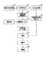
上記駆動装置40は、上記駆動枠11(及び検出枠12)を共振周波数にてx方向に振動駆動するためのもので、その構成は図3のブロック図にて表される。
同図に示されるように、上記駆動方向変位検出電極14a,14bからの各変位信号は、変位信号検出部41に出力される。この変位信号検出部41は、互いに逆相で検出された各変位信号を差動増幅し、駆動信号等に基づき混入した同相のノイズを除去した信号を生成する。
【0038】
上記変位信号検出部41において差動増幅された変位信号は、同期検波回路42においてx方向の変位に同期したタイミングにて同期検波されて振動振幅情報として振幅調節器43及び後述の可変増幅器47に出力される。図4に示されるように、この振幅調節器43は減算器43a及び増幅器43bを有しており、同減算器43aにおいて上記振幅調節器43に出力された振動振幅情報と振幅設定値との差が演算される。そして、上記増幅器43bにおいて、これら振動振幅情報及び振幅設定値の差に比例した信号が駆動信号の直流電圧成分Vdc(バイアス電圧)として生成される。従って、このときの駆動信号の直流電圧成分Vdcは、上記振動振幅情報が小さいときには、駆動電極13と駆動枠11(駆動側可動電極26)との電位差(バイアス電圧)が大きくなるように増加調節されて生成され、一方、同振動振幅情報が大きいときには、駆動電極13と駆動枠11(駆動側可動電極26)との電位差(バイアス電圧)が小さくなるように低減調節されて生成される。このような駆動信号の直流電圧成分Vdcの調節は、上記駆動枠11(及び検出枠12)のx方向の振動振幅が一定になるように同駆動枠11(及び検出枠12)の振動駆動力を制御するためである。このように生成された駆動信号の直流電圧成分Vdcは、加算器44に出力される。
【0039】
一方、上記変位信号検出部41において差動増幅された変位信号は、同時に90deg移相器45を介して略90度移相されて交流電圧成分生成部46に出力される。そして、上記交流電圧成分生成部46において、上記変位信号と同等の周波数を有して同変位信号に対して略90度移相され、駆動信号の交流電圧成分へと変換される一定の振幅を有する交流電圧成分が生成される。なお、この交流電圧成分を変位信号に対して略90度移相するのは、上記駆動枠11(及び検出枠12)を最も効率のよい共振点にて駆動し、発振しやすくするためである。このように生成された交流電圧成分は、可変増幅器47に出力される。
【0040】
上記可変増幅器47は、同期検波回路42からの振動振幅情報と所定の起動時振幅設定値とを比較する。この起動時振幅設定値は、駆動枠11(及び検出枠12)のx方向の振動振幅が小さい起動時の特性を判定するのに好適な値に設定されている。そして、この可変増幅器47は、上記同期検波回路42からの振動振幅情報と起動時振幅設定値との比較結果に応じて、上記交流電圧成分生成部46からの交流電圧成分の増幅率を選択的に切り替える。すなわち、同期検波回路42からの振動振幅情報が起動時振幅設定値よりも小さいときには、起動時であると判定して大きい側の増幅率にて上記交流電圧成分生成部46からの交流電圧成分を増幅する。一方、同期検波回路42からの振動振幅情報が起動時振幅設定値よりも大きいときには、定常時であると判定して小さい側の増幅率にて同交流電圧成分生成部46からの交流電圧成分を増幅する。このように可変増幅器47において選択的に切り替えられた増幅率にて増幅された交流電圧成分生成部46からの交流電圧成分は、選択された増幅率に応じて増幅された第1若しくは第2の振幅としての一定の振幅を有する駆動信号の交流電圧成分として加算器44に出力される。なお、小さい側の増幅率にて増幅生成された駆動信号の交流電圧成分の振幅(第1の振幅)も、上記駆動枠11(及び検出枠12)を共振周波数にて発振させるのに十分な大きさとなっている。
【0041】
上記加算器44において、上記調節された駆動信号の直流電圧成分Vdcと選択された増幅率に応じて増幅された一定の振幅を有する駆動信号の交流電圧成分とが加算されて駆動信号が生成される。そして、このように生成された駆動信号が前記駆動電極13に印加される。この駆動信号(印加電圧)の2乗に比例して上記駆動枠11(駆動側可動電極26)との間で発生する静電引力(振動駆動力)の振動により、同駆動枠11(及び検出枠12)はx方向に振動駆動される。従って、起動時には、立ち上げの時間を短縮するために大きい側の増幅率にて増幅生成された一定の振幅を有する駆動信号の交流電圧成分及び上記増減調節された直流電圧成分Vdcによるより大きな静電引力(振動駆動力)に基づき振動駆動される。また、定常時には小さい側の増幅率にて増幅生成された一定の振幅を有する駆動信号の交流電圧成分及び上記増減調節された直流電圧成分Vdcに基づき振動振幅が一定になるように振動駆動される。
【0042】
上記検出装置50は、電荷−電圧変換回路51,52及び差動増幅器53を備えており、加えられたz軸廻りの角速度を検出する。
上記電荷−電圧変換回路51,52はそれぞれ前記角速度検出電極15a,15bに接続されており、同角速度検出電極15a,15bとGNDレベルにある検出枠12全体との間での静電容量の振動に相当する電気信号(電圧)を発生する。この電気信号(電圧)は、検出枠12のy方向の振動に同期したレベル変化を示す交流信号となっている。なお、上記角速度検出電極15a,15bの静電容量の振動は、互いに逆相となっているため、これら電荷−電圧変換回路51,52においてそれぞれ発生する電気信号(電圧)も、互いに逆相となっている。
【0043】
上記差動増幅器53は電荷−電圧変換回路51,52に接続されており、各電荷−電圧変換回路51,52において互いに逆相に発生した電気信号(電圧)を差動増幅し、ノイズの相殺された角速度信号を発生する。
【0044】
ここで、検出枠12が駆動枠11とともにx方向に振動している状態において、z軸廻りの角速度が加わると、同検出枠12はy方向に振動することは既述のとおりである。このときの検出枠12のy方向の振動に基づく角速度信号は、加えられた角速度との間に所定の関係を有している。従って、この角速度信号により加えられた角速度が検出される。
【0045】
以上詳述したように、本実施形態によれば、以下に示す効果が得られるようになる。
(1)本実施形態では、同期検波回路42からの振動振幅情報が起動時振幅設定値よりも小さいときには、起動時であると判定されて大きい側の増幅率にて上記交流電圧成分生成部46からの一定の振幅を有する交流電圧成分が増幅される。そして、駆動装置40は、大きい側の増幅率にて増幅生成された一定の振幅を有する交流電圧成分及び検出された変位信号に基づき増減制御される直流電圧成分Vdc(バイアス電圧)からなる駆動信号を生成する。従って、この駆動信号に基づくより大きな静電引力(振動駆動力)により上記駆動枠11(及び検出枠12)をx方向に振動駆動することで、同駆動枠11(及び検出枠12)の起動時の振動振幅の立ち上げの時間を短縮することができる。
【0046】
(2)本実施形態では、同期検波回路42からの振動振幅情報が起動時振幅設定値よりも大きいときには、定常時であると判定されて小さい側の増幅率にて上記交流電圧成分生成部46からの一定の振幅を有する交流電圧成分が増幅される。そして、駆動装置40は、小さい側の増幅率にて増幅生成された一定の振幅を有する交流電圧成分及び検出された変位信号に基づき増減制御される直流電圧成分Vdc(バイアス電圧)からなる駆動信号を生成する。そして、この駆動信号に基づき、上記駆動枠11(及び検出枠12)の振動駆動力を制御して、同駆動枠11(及び検出枠12)のx方向の振動振幅が一定になるように調節する。
【0047】
従って、例えば駆動枠11(及び検出枠12)の経時変化や環境温度の変化などによって同駆動枠11(及び検出枠12)のx方向のQ値が変動した場合においても、駆動信号の直流電圧成分Vdcのみが増減制御され、交流電圧成分(振幅)は一定とされる。すなわち、駆動枠11(及び検出枠12)の経時変化や環境温度の変化などによって同駆動枠11(及び検出枠12)のx方向のQ値が変動した場合においても、駆動信号の交流電圧成分により変位信号に混入するノイズ量は安定したものとされる。このため、駆動枠11(及び検出枠12)の振動状態の検出誤差や角速度の検出出力のずれの変動を抑制することができる。
【0048】
(3)本実施形態では、同期検波回路42からの実際の振動振幅情報と起動時振幅設定値とを比較することで、起動時と定常時との区分をより厳密に行うことができる。
【0049】
(4)本実施形態では、駆動信号の直流電圧成分Vdcを、変位信号に基づき検出される駆動枠11(及び検出枠12)の振動振幅情報と振幅設定値との差に比例して増減制御した。従って、上記駆動枠11(及び検出枠12)の振動駆動力の位相遅れが抑えられ、同駆動枠11(及び検出枠12)に対する応答性の良い制御が可能となる。
【0050】
(5)本実施形態では、駆動信号の交流電圧成分は変位信号と略90度の位相差を有して生成される。従って、上記駆動枠11(及び検出枠12)を、最も効率のよい共振点にて振動駆動することができる。
【0051】
なお、本実施形態では、駆動信号の直流電圧成分Vdcを、変位信号に基づき検出される駆動枠11(及び検出枠12)の振動振幅情報と振幅設定値との差に比例して増減制御した。これに対して、駆動信号の直流電圧成分Vdcを、変位信号に基づき検出される駆動枠11(及び検出枠12)の振動振幅情報と振幅設定値との差を時間積分した値に比例して増減制御してもよい。すなわち、上記減算器43a及び増幅器43bからなる振幅調節器43に代えて、図5に示される減算器61a及び積分器61bからなる振幅調節器61を採用する。この場合、減算器61aにおいて上記振幅調節器61に出力された振動振幅情報と振幅設定値との差が演算され、上記積分器61bにおいて、これら振動振幅情報及び振幅設定値の差の時間積分に比例した信号が駆動信号の直流電圧成分Vdcとして生成される。このときの駆動信号の直流電圧成分Vdcも、上記振動振幅情報が小さいときには、駆動電極13と駆動枠11(駆動側可動電極26)との電位差(バイアス電圧)が大きくなるように増加調節されて生成され、一方、同振動振幅情報が大きいときには、駆動電極13と駆動枠11(駆動側可動電極26)との電位差(バイアス電圧)が小さくなるように低減調節されて生成される。従って、上記駆動枠11(及び検出枠12)のx方向の振動振幅が一定になるように同駆動枠11(及び検出枠12)の振動駆動力が同様に制御される。
【0052】
このように駆動信号の直流電圧成分Vdcを生成する場合、上記第1実施形態の(1)〜(3)、(5)の効果に加え、以下の効果が得られるようになる。
(1)駆動枠11(及び検出枠12)の振動振幅情報と振幅設定値との差が零になるよう、同駆動枠11(及び検出枠12)に対する精度の良い制御が可能となる。
【0053】
さらに、駆動信号の直流電圧成分Vdcを、変位信号に基づき検出される駆動枠11(及び検出枠12)の振動振幅情報と振幅設定値との差を時間積分した値及び同振動振幅情報と振幅設定値との差に比例した値の和に比例して増減制御してもよい。すなわち、上記減算器43a及び増幅器43bからなる振幅調節器43に代えて、図6に示される減算器62a、積分器62b、増幅器62c及び加算器62dからなる振幅調節器62を採用する。この場合、減算器62aにおいて上記振幅調節器62に出力された振動振幅情報と振幅設定値との差が演算される。そして、上記積分器62bを介してこれら振動振幅情報及び振幅設定値の差の時間積分に比例した信号が加算器62dに出力され、一方、増幅器62cを介してこれら振動振幅情報及び振幅設定値の差に比例した信号が加算器62dに出力される。そして、加算器62dにおいてこれら両信号の加算されたものが駆動信号の直流電圧成分Vdcとして生成される。このときの駆動信号の直流電圧成分Vdcも、上記振動振幅情報が小さいときには、駆動電極13と駆動枠11(駆動側可動電極26)との電位差(バイアス電圧)が大きくなるように増加調節されて生成され、一方、同振動振幅情報が大きいときには、駆動電極13と駆動枠11(駆動側可動電極26)との電位差(バイアス電圧)が小さくなるように低減調節されて生成される。従って、上記駆動枠11(及び検出枠12)のx方向の振動振幅が一定になるように同駆動枠11(及び検出枠12)の振動駆動力が同様に制御される。
【0054】
このように駆動信号の直流電圧成分(バイアス電圧)Vdcを生成する場合、上記第1実施形態の(1)〜(3)、(5)の効果に加え、以下の効果が得られるようになる。
【0055】
(1)駆動枠11(及び検出枠12)の振動駆動力の位相遅れが抑えられ、また、駆動枠11(及び検出枠12)の振動振幅情報と振幅設定値との差が零になるよう、同駆動枠11(及び検出枠12)に対する応答性及び精度の良い制御が可能となる。
【0056】
(第2実施形態)
以下、本発明の第2実施形態を適用した角速度センサについて、図7に基づき説明する。なお、第2実施形態は、第1実施形態の可変増幅器47に代えて切り替えスイッチを使用して信号経路を切り替える構成に変更したのみであるため、同様の部分についてはその詳細な説明は省略する。なお、本実施形態においても、振幅調節器43に代えて、振幅調節器61,62のいずれか1つの構成を採用してもよい。
【0057】
図7に示されるように、前記同期検波回路42からの振動振幅情報は、切り替えスイッチ63に出力されている。また、前記交流電圧成分生成部46において生成された一定の振幅を有する交流電圧成分は、上記切り替えスイッチ63に直接、出力されるもの(第1の信号経路)と、増幅器64を介して同切り替えスイッチ63に出力されるもの(第2の信号経路)とに分岐されている。
【0058】
上記切り替えスイッチ63は、同期検波回路42からの振動振幅情報と前記起動時振幅設定値とを比較する。そして、この切り替えスイッチ63は、上記同期検波回路42からの振動振幅情報と起動時振幅設定値との比較結果に応じて、前記加算器44へと出力する上記交流電圧成分生成部46からの一定の振幅を有する交流電圧成分の信号経路を選択的に切り替える。すなわち、同期検波回路42からの振動振幅情報が起動時振幅設定値よりも小さいときには、起動時であると判定して上記交流電圧成分生成部46からの交流電圧成分は、増幅器64を介して増幅される。このように増幅された上記交流電圧成分生成部46からの交流電圧成分は、一定の振幅(第2の振幅)を有する駆動信号の交流電圧成分として加算器44に出力される。一方、同期検波回路42からの振動振幅情報が起動時振幅設定値よりも大きいときには、定常時であると判定して上記交流電圧成分生成部46からの交流電圧成分は直接、一定の振幅(第1の振幅)を有する駆動信号の交流電圧成分として加算器44に出力される。なお、上記交流電圧成分生成部46から直接、加算器44に出力される駆動信号の交流電圧成分の振幅(第1の振幅)も、上記駆動枠11(及び検出枠12)を共振周波数にて発振させるのに十分な大きさとなっている。
【0059】
上記加算器44において、前記調節された駆動信号の直流電圧成分Vdcと選択された信号経路に応じて処理された一定の振幅を有する駆動信号の交流電圧成分とが加算されて駆動信号が生成される。そして、このように生成された駆動信号が前記駆動電極13に印加される。この駆動信号(印加電圧)の2乗に比例して上記駆動枠11(駆動側可動電極26)との間で発生する静電引力(振動駆動力)の振動により、同駆動枠11(及び検出枠12)はx方向に振動駆動される。
【0060】
以上詳述したように、本実施形態によれば、前記第1実施形態と同様の効果が得られるようになる。
(第3実施形態)
以下、本発明の第3実施形態を適用した角速度センサについて、図8に基づき説明する。なお、第1実施形態では、起動時と定常時とを区分するために、同期検波回路42からの振動振幅情報と起動時振幅設定値とを比較した。これに対して、第3実施形態では、起動後の経過時間に基づき起動時と定常時とを区分するように変更した。従って、その他の部分については同様の構成であるため、その詳細な説明は省略する。なお、本実施形態においても、振幅調節器43に代えて振幅調節器61,62のいずれか1つの構成を採用してもよい。
【0061】
本実施形態では、前記可変増幅器47にタイマ65が接続されている。このタイマ65は、例えば抵抗器と静電容量からなり、そのRCの時定数により起動後の経過時間を決定する。そして、この起動後の経過時間に基づく起動時と定常時との区分に応じて、同様に可変増幅器47は上記交流電圧成分生成部46からの一定の振幅を有する交流電圧成分の増幅率を選択的に切り替える。
【0062】
以上詳述したように、本実施形態によれば、前記第1実施形態の(1)、(2)、(4)、(5)の効果に加えて以下に示す効果が得られるようになる。
(1)本実施形態では、タイマ65により決定される起動後の経過時間に基づき起動時と定常時とを区分するようにした。従って、この起動時と定常時とを区分するための構成(回路構成)を簡易化することができる。
【0063】
(第4実施形態)
以下、本発明の第4実施形態を適用した角速度センサについて、図9に基づき説明する。なお、第2実施形態では、起動時と定常時とを区分するために、同期検波回路42からの振動振幅情報と起動時振幅設定値とを比較した。これに対して、第4実施形態では、起動後の経過時間に基づき起動時と定常時とを区分するように変更した。従って、その他の部分については同様の構成であるため、その詳細な説明は省略する。なお、本実施形態においても、振幅調節器43に代えて振幅調節器61,62のいずれか1つの構成を採用してもよい。
【0064】
本実施形態では、前記切り替えスイッチ63にタイマ66が接続されている。このタイマ66は、例えば抵抗器と静電容量からなり、そのRCの時定数により起動後の経過時間を決定する。そして、この起動後の経過時間に基づく起動時と定常時との区分に応じて、同様に切り替えスイッチ63は上記加算器44へと出力する上記交流電圧成分生成部46からの一定の振幅を有する交流電圧成分の信号経路を選択的に切り替える。
【0065】
以上詳述したように、本実施形態によれば、前記第3実施形態と同様の効果が得られるようになる。
(第5実施形態)
以下、本発明の第5実施形態を適用した角速度センサについて、図10に基づき説明する。なお、第5実施形態は、第1実施形態の交流電圧成分生成部46を割愛して別の可変増幅器67を採用したのみの変更であるため、同様の部分の構成についてはその詳細な説明は省略する。なお、本実施形態においても、振幅調節器43に代えて振幅調節器61,62のいずれか1つの構成を採用してもよい。
【0066】
本実施形態では、前記90deg移相器45において略90度移相された変位信号を可変増幅器67を介して増幅することで、駆動信号の交流電圧成分が生成される。このとき、第1実施形態に準じて、この可変増幅器67は、上記同期検波回路42からの振動振幅情報と起動時振幅設定値との比較結果に応じて、上記90deg移相器45において略90度移相された変位信号(交流電圧成分)の増幅率を選択的に切り替える。すなわち、同期検波回路42からの振動振幅情報が起動時振幅設定値よりも小さいときには、起動時であると判定して大きい側の増幅率(第2の増幅率)にて上記90deg移相器45からの変位信号(交流電圧成分)を増幅する。一方、同期検波回路42からの振動振幅情報が起動時振幅設定値よりも大きいときには、定常時であると判定して小さい側の増幅率(第1の増幅率)にて同90deg移相器45からの変位信号(交流電圧成分)を増幅する。あるいは、可変増幅器67による上記増幅率の切り替えを、直流電圧成分Vdcと所定の起動時設定電圧との比較結果に応じて行ってもよい。この場合、簡易な構成で、且つ、厳密に起動時と定常時との区分を行うことができる。このように可変増幅器67において選択的に切り替えられた増幅率にて増幅された90deg移相器45からの変位信号(交流電圧成分)は、駆動信号の交流電圧成分として加算器44に出力される。なお、定常時において上記駆動枠11(及び検出枠12)の振動状態(振動振幅)が安定すれば、同駆動枠11(及び検出枠12)の振動に基づく変位信号を増幅するのみで、一定の振幅を有する駆動信号の交流電圧成分が生成される。このため、例えば、駆動信号の交流電圧成分を前記交流電圧成分生成部46において単独で生成する場合に比べ、その回路構成が簡易化される。なお、上記可変増幅器67における小さい側の増幅率(第1の増幅率)は、上記駆動枠11(及び検出枠12)を共振周波数にて発振させるためにループゲインが1よりも大きくなるように設定されている。
【0067】
以上詳述したように、本実施形態によれば、前記第1実施形態の効果に加えて以下に示す効果が得られるようになる。
(1)本実施形態では、定常時において駆動枠11(及び検出枠12)の振動状態(振動振幅)が安定すれば、同駆動枠11(及び検出枠12)の振動に基づく変位信号を移相増幅するのみで、一定の振幅を有する駆動信号の交流電圧成分を生成することができる。このため、例えば、駆動信号の交流電圧成分を前記交流電圧成分生成部46において単独で生成する場合に比べ、その回路構成を簡易化することができる。
【0068】
(2)本実施形態では、正弦波として検出される変位信号を増幅することにより、駆動信号の交流電圧成分を正弦波として生成する。従って、例えば駆動信号の交流電圧成分を矩形波として生成した場合に混入する高調波のノイズ発生を抑制することができる。
【0069】
なお、本発明の実施の形態は上記実施形態に限定されるものではなく、次のように変更してもよい。
・前記第2〜第4実施形態においても同様に、交流電圧成分生成部46を割愛して別の可変増幅器若しくは増幅器を採用してもよい。
【0070】
・前記第1、第3及び第5実施形態における可変増幅器47,67は、小さい側の増幅率に対して大きい側の増幅率が、例えば10倍程度とであることが好ましい。
【0071】
また、第2及び第4実施形態における増幅器64の増幅率としては、例えば10倍程度であることが好ましい。
・前記第1、第3及び第5実施形態における可変増幅器としては、例えば図11〜図18に示される抵抗器及びオペアンプ70からなる負帰還増幅器などがある。すなわち、非反転入力端子と出力端子との間の抵抗値を固定し、反転入力端子側の抵抗値を切り替えスイッチにて変えて可変増幅する構成(図11、図12、図15及び図16)や、反転入力端子側の抵抗値を固定し、非反転入力端子と出力端子との間の抵抗値を切り替えスイッチにて変えて可変増幅する構成(図13、図14、図17及び図18)などがある。
【0072】
・前記第1〜第4実施形態における駆動信号の交流電圧成分としては、例えば正弦波であってもよいし、矩形波などであってもよい。
・前記各実施形態においては、90deg移相器45を採用したが、例えば微分器や積分器を採用してもよい。
【0073】
・前記各実施形態においては、90deg移相器45、微分器若しくは積分器にて略90度移相するようにしたが、その他の角度にて移相するようにしてもよい。
【0074】
・前記各実施形態においては、定常時と起動時とで2段階に区分したが、例えば起動時を更に細分化して各状態に応じて信号処理(増幅率の変更、信号経路の切り替え)を行うようにしても、本発明を逸脱するものではない。
【0075】
・前記各実施形態において採用された検出枠12のy方向の振動検出構造(検出装置50)は一例であってその他の構造を採用してもよい。
・前記各実施形態においては、駆動枠11を直線状に伸びるばね梁31〜34を介して浮動体アンカーa11〜a14に支持した。これに対して、駆動枠11を略U字状に折り返されて伸びるばね梁を介して浮動体アンカーa11〜a14に支持するようにしてもよい。
【0076】
・前記各実施形態において採用された角速度センサの構造は一例であってその構造は任意である。
次に、以上の実施形態から把握することができる請求項以外の技術的思想を、その効果とともに以下に記載する。
【0077】
(イ)請求項1〜6のいずれかに記載の振動子駆動装置において、前記駆動信号の直流電圧成分は、前記変位信号に基づき検出される前記静電駆動型振動子の振動振幅と設定振幅との差に比例して増減制御されることを特徴とする振動子駆動装置。同構成によれば、上記駆動信号の直流電圧成分は、変位信号に基づき検出される静電駆動型振動子の振動振幅と設定振幅との差に比例して増減制御される。従って、上記静電駆動型振動子の振動駆動力の位相遅れが抑えられ、同静電駆動型振動子に対する応答性の良い制御が可能となる。
【0078】
(ロ)請求項1〜6のいずれかに記載の振動子駆動装置において、前記駆動信号の直流電圧成分は、前記変位信号に基づき検出される前記静電駆動型振動子の振動振幅と設定振幅との差を時間積分した値に比例して増減制御されることを特徴とする振動子駆動装置。同構成によれば、上記駆動信号の直流電圧成分は、変位信号に基づき検出される静電駆動型振動子の振動振幅と設定振幅との差を時間積分した値に比例して増減制御される。従って、上記静電駆動型振動子の振動振幅と設定振幅との差が零になるよう、同静電駆動型振動子に対する精度の良い制御が可能となる。
【0079】
(ハ)請求項1〜6のいずれかに記載の振動子駆動装置において、前記駆動信号の直流電圧成分は、前記変位信号に基づき検出される前記静電駆動型振動子の振動振幅と設定振幅との差を時間積分した値及び該振動振幅と設定振幅との差に比例した値の和に比例して増減制御されることを特徴とする振動子駆動装置。同構成によれば、上記駆動信号の直流電圧成分は、変位信号に基づき検出される静電駆動型振動子の振動振幅と設定振幅との差を時間積分した値及び同振動振幅と設定振幅との差に比例した値の和に比例して増減制御される。従って、上記静電駆動型振動子の振動駆動力の位相遅れが抑えられ、また、静電駆動型振動子の振動振幅と設定振幅との差が零になるよう、同静電駆動型振動子に対する応答性及び精度の良い制御が可能となる。
【0080】
(ニ)請求項1〜6及び上記(イ)〜(ハ)のいずれかに記載の振動子駆動装置において、前記駆動信号の交流電圧成分は、前記変位信号と略90度の位相差を有して生成されることを特徴とする振動子駆動装置。同構成によれば、上記駆動信号の交流電圧成分は変位信号と略90度の位相差を有して生成される。従って、上記静電駆動型振動子は、最も効率のよい共振点にて振動駆動される。
【0081】
【発明の効果】
以上詳述したように、請求項1〜4に記載の発明によれば、静電駆動型振動子の振動状態の検出誤差等の変動を抑制し、且つ、同振動子の起動時の振動振幅の立ち上げ時間を短縮することができる。特に、請求項4に記載の発明によれば、交流電圧成分生成手段の構成(回路構成)を簡易化することができる。
【0082】
請求項5に記載の発明によれば、定常時と起動時との区分を起動後の経過時間に基づき簡易な構成(回路構成)にて行うことができる。
請求項6に記載の発明によれば、定常時と起動時との区分を実際の静電駆動型振動子の振動状態である振動振幅と起動時設定振幅とを比較することでより厳密に行うことができる。
【0083】
請求項7に記載の発明によれば、定常時と起動時との区分を直流電圧成分と起動時設定電圧とを比較することで簡易な構成で、且つ、精密に行うことができる。
【図面の簡単な説明】
【図1】本発明の第1実施形態を適用した角速度センサを示す概略図。
【図2】同実施形態の駆動電極に印加される駆動信号を示すタイムチャート。
【図3】同実施形態を示すブロック図。
【図4】同実施形態の振幅調節器を示すブロック図。
【図5】同実施形態の振幅調節器の別例を示すブロック図。
【図6】同実施形態の振幅調節器の別例を示すブロック図。
【図7】本発明の第2実施形態を示すブロック図。
【図8】本発明の第3実施形態を示すブロック図。
【図9】本発明の第4実施形態を示すブロック図。
【図10】本発明の第5実施形態を示すブロック図。
【図11】可変増幅器の一例を示す回路図。
【図12】可変増幅器の一例を示す回路図。
【図13】可変増幅器の一例を示す回路図。
【図14】可変増幅器の一例を示す回路図。
【図15】可変増幅器の一例を示す回路図。
【図16】可変増幅器の一例を示す回路図。
【図17】可変増幅器の一例を示す回路図。
【図18】可変増幅器の一例を示す回路図。
【図19】従来の形態を示すブロック図。
【図20】従来の別の形態を示すブロック図。
【符号の説明】
12 振動子としての検出枠
13 駆動電極
40 駆動装置
42 同期検波回路
43,61,62 振幅調節器
46 交流電圧成分生成部
47,67 可変増幅器
63 切り替えスイッチ
64 増幅器
65,66 タイマ[0001]
BACKGROUND OF THE INVENTION
The present invention relates to a vibrator driving device that vibrates and drives an electrostatic drive type vibrator included in an angular velocity sensor, for example.And angular velocity sensor provided with vibrator driving deviceIt is about.
[0002]
[Prior art]
2. Description of the Related Art Conventionally, as a vibrator driving apparatus that vibrates and drives an electrostatic drive type vibrator provided in an angular velocity sensor, for example, a vibrator represented by a block diagram in FIG. 19 is known. As shown in the figure, the displacement due to the vibration in the drive direction of the electrostatic drive type vibrator is output from the drive direction
[0003]
The displacement signal output to the displacement signal detector 82 is synchronously detected at a timing synchronized with the displacement in the driving direction in the
[0004]
The vibration amplitude information output to the
[0005]
The
[0006]
[Problems to be solved by the invention]
By the way, since the AC voltage component of the drive signal has the same frequency as the displacement signal, the AC voltage component of the drive signal is a noise source of the displacement signal. That is, the AC voltage component of the drive signal causes a detection error of the vibration state of the electrostatic drive type vibrator. Further, for example, when the angular velocity is detected in a state where the drive device is applied to a vibration type angular velocity sensor and the electrostatic drive type vibrator is driven to vibrate, it causes a deviation in detection output. Such deviations in vibration state detection errors and angular velocity detection outputs can be easily corrected if they have unique values.
[0007]
However, when the Q value in the driving direction of the electrostatic drive vibrator changes due to a change with time of the electrostatic drive vibrator or a change in environmental temperature, the vibration amplitude in the driving direction of the vibrator becomes constant. As described above, when the AC voltage component of the drive signal is adjusted to increase or decrease as described above, the amount of noise mixed in the displacement signal varies. Therefore, the detection error of the vibration state of the electrostatic drive type vibrator and the deviation of the detection output of the angular velocity will fluctuate.
[0008]
Therefore, in order to suppress such fluctuations in the detection error of the vibration state of the electrostatic drive vibrator and the deviation in the detection output of the angular velocity, the amplitude of the AC voltage component of the drive signal is made constant, and the DC voltage component (bias voltage) It has been proposed by the applicants to control the vibration driving force of the vibrator so that the vibration amplitude in the driving direction of the vibrator becomes constant by adjusting the increase / decrease only).
[0009]
That is, as shown in the block diagram of FIG. 20, the displacement due to the vibration in the driving direction of the electrostatic drive type vibrator is output from the driving direction
[0010]
The displacement signal output to the displacement
[0011]
On the other hand, the displacement signal output to the displacement
[0012]
In the
[0013]
In such a vibrator driving device, the AC voltage component of the drive signal is set to have a relatively small amplitude in order to reduce the amount of noise mixed in the displacement signal based on the AC voltage component of the drive signal. Yes. However, when controlling the vibration driving force of the vibrator by adjusting only the DC voltage component of the drive signal, the adjustment range of the DC voltage component (bias voltage) is restricted by the power supply voltage capability. The vibration drive force at startup (maximum drive force) cannot be sufficiently obtained with respect to the vibration drive force during steady state. Therefore, it may take time to start up the vibrator until the vibrator is brought into a required vibration state. This tendency becomes more prominent as the vibrator has a higher Q value.
[0014]
SUMMARY OF THE INVENTION An object of the present invention is to provide a vibrator driving device that can suppress fluctuations in the detection error of the vibration state of an electrostatically driven vibrator and can shorten the rise time of vibration amplitude when the vibrator is activated.And angular velocity sensor provided with vibrator driving deviceIs to provide.
[0015]
[Means for Solving the Problems]
In order to solve the above problems, the invention according to claim 1 is directed to a driving unit that outputs a driving signal to the electrostatic drive type vibrator to drive the electrostatic drive type vibrator, and the electrostatic drive. In a vibrator driving apparatus comprising: a detecting means for detecting a displacement due to vibration of a type vibrator as a displacement signal; and an amplitude adjusting means for generating and controlling a driving signal output from the driving means based on the detected displacement signal. The amplitude adjusting means is in a steady state.FixedAC voltage component generation means for generating an AC voltage component of the drive signal having a first amplitude and generating an AC voltage component of the drive signal having a second amplitude larger than the first amplitude at the time of startup DC voltage component generation means for generating a DC voltage component of the drive signal that is controlled to increase or decrease based on the detected displacement signal,FixedBased on a drive signal composed of an AC voltage component and a DC voltage component having a first amplitude, the vibration drive force of the electrostatic drive vibrator is controlled to make the vibration amplitude of the electrostatic drive vibrator constant. And at the time of start-up, a larger vibration driving force is applied to the electrostatic drive vibrator based on the generated drive signal composed of the AC voltage component and the DC voltage component having the second amplitude. The gist is to increase the vibration amplitude of the electrostatically driven vibrator by applying.
[0016]
According to a second aspect of the present invention, in the vibrator driving device according to the first aspect, the AC voltage component generation unit includes an AC voltage component generation unit that generates an AC voltage component having a predetermined amplitude, a steady state, and a startup time. The AC voltage component having the predetermined amplitude is amplified with a different amplification factor in response to the generation of the AC voltage component of the drive signal having the first amplitude and the AC voltage component of the drive signal having the second amplitude. The gist is to include an amplifying unit.
[0017]
According to a third aspect of the present invention, in the vibrator driving device according to the first aspect, the AC voltage component generation means generates a first signal path for generating an AC voltage component of the drive signal having the first amplitude. And a second signal path for generating an AC voltage component of the drive signal having the second amplitude, and switching between the first signal path and the second signal path according to a steady state and a startup time The gist of the present invention is to include a switching unit that performs the above.
[0018]
According to a fourth aspect of the present invention, there is provided driving means for outputting a drive signal to the electrostatic drive type vibrator to drive the electrostatic drive type vibrator, and displacement due to vibration of the electrostatic drive type vibrator is displaced. In the vibrator driving device including detection means for detecting as a signal and amplitude adjustment means for generating and controlling a drive signal output from the drive means based on the detected displacement signal, the amplitude adjustment means is in a steady state. Phase shift amplification of the displacement signal at a first amplification factor to generate an AC voltage component of the drive signal having a constant amplitude, and a second amplification factor larger than the first amplification factor at startup And AC voltage component generation means for phase-amplifying the displacement signal to generate an AC voltage component of the drive signal, and generating a DC voltage component of the drive signal that is controlled to increase or decrease based on the detected displacement signal. DC voltage component generation means In a steady state, the vibration driving force of the electrostatically driven vibrator is controlled based on a drive signal composed of an AC voltage component and a DC voltage component having a constant amplitude amplified by the first amplification factor. Then, adjustment is made so that the vibration amplitude of the electrostatic drive type vibrator becomes constant, and at the time of start-up, a drive signal composed of an AC voltage component and a DC voltage component amplified by the second amplification factor is generated. Based on this, the gist is to apply a larger vibration driving force to the electrostatic drive vibrator to increase the vibration amplitude of the electrostatic drive vibrator.
[0019]
The gist of the invention according to claim 5 is that, in the vibrator driving device according to any one of claims 1 to 4, the steady time and the startup time are classified by an elapsed time after the startup. .
[0020]
According to a sixth aspect of the present invention, in the vibrator driving device according to any one of the first to fourth aspects, the electrostatic drive type vibration detected based on the displacement signal at the steady time and the startup time. The gist is that they are classified by comparing the vibration amplitude of the child and the set amplitude at start-up.
[0021]
According to a seventh aspect of the present invention, in the vibrator driving device according to any one of the first to fourth aspects, the steady state and the startup time are classified by comparing the DC voltage component and the startup setting voltage. The gist is that
The gist of an eighth aspect of the invention is an angular velocity sensor including the vibrator driving device according to any one of the first to seventh aspects.
[0022]
In the vibrator driving device according to any one of claims 1 to 7, the driving amplitude may be set to be approximately proportional to the driving resonance frequency.
(Function)
According to the first to fourth aspects of the present invention, the amplitude adjusting means converts the AC voltage component having the first amplitude and the detected displacement signal by the AC voltage component generating means and the DC voltage component generating means in a steady state. A drive signal composed of a DC voltage component that is controlled to be increased or decreased is generated. Based on this drive signal, the vibration drive force of the electrostatic drive vibrator is controlled to adjust the vibration amplitude in the drive direction of the electrostatic drive vibrator to be constant. Therefore, even when the Q value in the driving direction of the electrostatic drive vibrator changes due to, for example, a change with time of the electrostatic drive vibrator or a change in environmental temperature, only the DC voltage component of the drive signal is controlled to increase or decrease. The AC voltage component (amplitude) is constant. That is, even when the Q value in the driving direction of the electrostatic drive vibrator changes due to a change with time of the electrostatic drive vibrator or a change in environmental temperature, it is mixed into the displacement signal by the AC voltage component of the drive signal. The amount of noise is assumed to be stable. For this reason, the fluctuation of the detection error or the like of the vibration state of the electrostatically driven vibrator is suppressed by holding a unique value.
[0023]
On the other hand, the amplitude adjusting means controls the increase / decrease based on the AC voltage component having the second amplitude larger than the first amplitude and the detected displacement signal by the AC voltage component generating means and the DC voltage component generating means at the time of startup. A drive signal composed of a DC voltage component is generated. Based on this drive signal, a larger vibration driving force is applied to the electrostatic drive vibrator to increase the vibration amplitude of the electrostatic drive vibrator. Accordingly, the rise time of the vibration amplitude at the time of starting the electrostatic drive type vibrator is shortened.
[0024]
In particular, according to the fourth aspect of the present invention, the AC voltage component of the drive signal is generated only by phase-shifting and amplifying the displacement signal regardless of whether it is steady or activated. Further, if the vibration state (vibration amplitude) of the electrostatic drive type vibrator is stabilized, the displacement voltage based on the vibration of the vibrator is simply phase-shifted and amplified, and the AC voltage component of the drive signal having a constant amplitude is Generated. For this reason, for example, the configuration (circuit configuration) of the AC voltage component generation unit is simplified as compared with the case where the AC voltage component of the drive signal is generated alone.
[0025]
According to the fifth aspect of the present invention, it is possible to distinguish between the steady state and the startup time with a simple configuration (circuit configuration) based on the elapsed time after the startup.
According to the sixth aspect of the invention, the steady state and the startup can be classified more strictly by comparing the vibration amplitude, which is the actual vibration state of the electrostatic drive vibrator, with the set amplitude at the start. .
[0026]
According to the seventh aspect of the present invention, it is possible to accurately and accurately distinguish between the steady state and the startup time by comparing the DC voltage component with the startup set voltage.
[0027]
DETAILED DESCRIPTION OF THE INVENTION
(First embodiment)
Hereinafter, an angular velocity sensor to which a first embodiment of the present invention is applied will be described with reference to FIGS.
[0028]
As shown in FIG. 1, the
[0029]
The
[0030]
The four corners of the
[0031]
The detection frame 12 has a smaller width and length than the
[0032]
The
[0033]
The drive direction
[0034]
The angular
[0035]
The applied angular velocity around the z-axis is detected by the vibration state in the y direction of the detection frame 12 when the detection frame 12 is vibrating in the x direction together with the
[0036]
Next, an electrical configuration relating to angular velocity detection of the angular velocity sensor will be described.
As shown in FIG. 1, the angular velocity sensor mainly includes a
[0037]
The
As shown in the figure, the displacement signals from the drive direction
[0038]
The displacement signal differentially amplified in the displacement
[0039]
On the other hand, the displacement signal differentially amplified in the displacement
[0040]
The
[0041]
In the
[0042]
The
The charge-
[0043]
The differential amplifier 53 is connected to the charge-
[0044]
Here, as described above, in the state where the detection frame 12 is vibrating in the x direction together with the
[0045]
As described above in detail, according to the present embodiment, the following effects can be obtained.
(1) In the present embodiment, when the vibration amplitude information from the
[0046]
(2) In the present embodiment, when the vibration amplitude information from the
[0047]
Therefore, even when the Q value in the x direction of the drive frame 11 (and the detection frame 12) fluctuates due to, for example, a change with time of the drive frame 11 (and the detection frame 12) or a change in environmental temperature, the DC voltage of the drive signal is changed. Only the component Vdc is controlled to increase or decrease, and the AC voltage component (amplitude) is kept constant. That is, even when the Q value in the x direction of the drive frame 11 (and the detection frame 12) fluctuates due to a change with time of the drive frame 11 (and the detection frame 12), a change in environmental temperature, or the like, the AC voltage component of the drive signal Therefore, the amount of noise mixed in the displacement signal is stabilized. For this reason, it is possible to suppress fluctuations in the detection error of the vibration state of the drive frame 11 (and the detection frame 12) and the deviation in the detection output of the angular velocity.
[0048]
(3) In this embodiment, by comparing the actual vibration amplitude information from the
[0049]
(4) In the present embodiment, the DC voltage component Vdc of the drive signal is increased or decreased in proportion to the difference between the vibration amplitude information of the drive frame 11 (and the detection frame 12) detected based on the displacement signal and the amplitude set value. did. Therefore, the phase delay of the vibration driving force of the drive frame 11 (and the detection frame 12) is suppressed, and control with good response to the drive frame 11 (and the detection frame 12) is possible.
[0050]
(5) In this embodiment, the AC voltage component of the drive signal is generated with a phase difference of approximately 90 degrees from the displacement signal. Therefore, the drive frame 11 (and the detection frame 12) can be driven to vibrate at the most efficient resonance point.
[0051]
In the present embodiment, the DC voltage component Vdc of the drive signal is controlled to increase or decrease in proportion to the difference between the vibration amplitude information of the drive frame 11 (and the detection frame 12) detected based on the displacement signal and the amplitude set value. . In contrast, the DC voltage component Vdc of the drive signal is proportional to the value obtained by time-integrating the difference between the vibration amplitude information of the drive frame 11 (and the detection frame 12) detected based on the displacement signal and the amplitude setting value. Increase / decrease control may be performed. That is, instead of the
[0052]
When the DC voltage component Vdc of the drive signal is generated in this way, the following effects can be obtained in addition to the effects (1) to (3) and (5) of the first embodiment.
(1) The drive frame 11 (and the detection frame 12) can be accurately controlled so that the difference between the vibration amplitude information of the drive frame 11 (and the detection frame 12) and the amplitude setting value becomes zero.
[0053]
Further, the DC voltage component Vdc of the drive signal is a value obtained by time-integrating the difference between the vibration amplitude information of the drive frame 11 (and the detection frame 12) detected based on the displacement signal and the amplitude setting value, and the vibration amplitude information and amplitude. The increase / decrease control may be performed in proportion to the sum of the values proportional to the difference from the set value. That is, instead of the
[0054]
When the DC voltage component (bias voltage) Vdc of the drive signal is generated as described above, the following effects can be obtained in addition to the effects (1) to (3) and (5) of the first embodiment. .
[0055]
(1) The phase delay of the vibration driving force of the drive frame 11 (and the detection frame 12) is suppressed, and the difference between the vibration amplitude information of the drive frame 11 (and the detection frame 12) and the amplitude setting value is zero. Thus, it is possible to control the drive frame 11 (and the detection frame 12) with high responsiveness and accuracy.
[0056]
(Second Embodiment)
Hereinafter, an angular velocity sensor to which a second embodiment of the present invention is applied will be described with reference to FIG. In the second embodiment, since only the signal path is switched using a changeover switch instead of the
[0057]
As shown in FIG. 7, the vibration amplitude information from the
[0058]
The
[0059]
The
[0060]
As described above in detail, according to this embodiment, the same effect as that of the first embodiment can be obtained.
(Third embodiment)
Hereinafter, an angular velocity sensor to which a third embodiment of the present invention is applied will be described with reference to FIG. In the first embodiment, the vibration amplitude information from the
[0061]
In the present embodiment, a
[0062]
As described in detail above, according to the present embodiment, the following effects can be obtained in addition to the effects (1), (2), (4), and (5) of the first embodiment. .
(1) In the present embodiment, the startup time and the steady time are distinguished based on the elapsed time after the startup determined by the
[0063]
(Fourth embodiment)
Hereinafter, an angular velocity sensor to which a fourth embodiment of the present invention is applied will be described with reference to FIG. In the second embodiment, the vibration amplitude information from the
[0064]
In the present embodiment, a
[0065]
As described above in detail, according to the present embodiment, the same effect as in the third embodiment can be obtained.
(Fifth embodiment)
Hereinafter, an angular velocity sensor to which a fifth embodiment of the invention is applied will be described with reference to FIG. Note that the fifth embodiment is a modification in which the AC voltage
[0066]
In the present embodiment, an AC voltage component of the drive signal is generated by amplifying the displacement signal phase shifted by about 90 degrees in the 90
[0067]
As described above in detail, according to the present embodiment, the following effects can be obtained in addition to the effects of the first embodiment.
(1) In the present embodiment, when the vibration state (vibration amplitude) of the drive frame 11 (and the detection frame 12) is stabilized in a steady state, the displacement signal based on the vibration of the drive frame 11 (and the detection frame 12) is transferred. An AC voltage component of a drive signal having a constant amplitude can be generated only by phase amplification. For this reason, for example, the circuit configuration can be simplified as compared with the case where the AC voltage component of the drive signal is generated alone in the AC voltage
[0068]
(2) In the present embodiment, an alternating voltage component of the drive signal is generated as a sine wave by amplifying the displacement signal detected as a sine wave. Therefore, for example, it is possible to suppress the generation of harmonic noise mixed when the AC voltage component of the drive signal is generated as a rectangular wave.
[0069]
In addition, embodiment of this invention is not limited to the said embodiment, You may change as follows.
Similarly, in the second to fourth embodiments, the AC voltage
[0070]
In the
[0071]
The amplification factor of the
Examples of the variable amplifier in the first, third, and fifth embodiments include a negative feedback amplifier including a resistor and an
[0072]
The AC voltage component of the drive signal in the first to fourth embodiments may be, for example, a sine wave or a rectangular wave.
In each of the above embodiments, the 90
[0073]
In each of the above embodiments, the 90
[0074]
In each of the above-described embodiments, it is divided into two stages according to the steady state and the start-up time. For example, the start-up time is further subdivided and signal processing (amplification rate change, signal path switching) is performed according to each state. Even so, it does not depart from the present invention.
[0075]
The vibration detection structure (detection device 50) in the y direction of the detection frame 12 employed in each of the above embodiments is an example, and other structures may be employed.
In each of the above embodiments, the
[0076]
The structure of the angular velocity sensor employed in each of the above embodiments is an example, and the structure is arbitrary.
Next, technical ideas other than the claims that can be grasped from the above embodiments will be described together with the effects thereof.
[0077]
(A) In the vibrator drive device according to any one of claims 1 to 6, the DC voltage component of the drive signal is a vibration amplitude and a set amplitude of the electrostatic drive vibrator detected based on the displacement signal. The vibrator driving device is controlled to increase or decrease in proportion to the difference between According to this configuration, the DC voltage component of the drive signal is controlled to increase or decrease in proportion to the difference between the vibration amplitude and the set amplitude of the electrostatic drive vibrator detected based on the displacement signal. Accordingly, the phase delay of the vibration driving force of the electrostatic drive vibrator is suppressed, and control with good response to the electrostatic drive vibrator can be performed.
[0078]
(B) In the vibrator drive device according to any one of claims 1 to 6, the DC voltage component of the drive signal is a vibration amplitude and a set amplitude of the electrostatic drive vibrator detected based on the displacement signal. The vibrator drive device is controlled to increase or decrease in proportion to a value obtained by integrating the difference with time. According to this configuration, the DC voltage component of the drive signal is controlled to increase or decrease in proportion to a value obtained by time-integrating the difference between the vibration amplitude of the electrostatic drive vibrator detected based on the displacement signal and the set amplitude. . Therefore, it is possible to control the electrostatic drive vibrator with high accuracy so that the difference between the vibration amplitude and the set amplitude of the electrostatic drive vibrator is zero.
[0079]
(C) In the vibrator driving device according to any one of claims 1 to 6, the DC voltage component of the drive signal is a vibration amplitude and a set amplitude of the electrostatic drive vibrator detected based on the displacement signal. A vibrator driving device is controlled to increase or decrease in proportion to a sum of a value obtained by time integration of the difference between and a value proportional to a difference between the vibration amplitude and the set amplitude. According to this configuration, the DC voltage component of the drive signal includes a value obtained by time-integrating the difference between the vibration amplitude and the set amplitude of the electrostatic drive vibrator detected based on the displacement signal, and the vibration amplitude and the set amplitude. Increase / decrease control is performed in proportion to the sum of the values proportional to the difference. Therefore, the electrostatic drive vibrator is suppressed so that the phase delay of the vibration drive force of the electrostatic drive vibrator is suppressed, and the difference between the vibration amplitude and the set amplitude of the electrostatic drive vibrator is zero. Can be controlled with high responsiveness and accuracy.
[0080]
(D) In the vibrator driving device according to any one of claims 1 to 6 and (a) to (c), the AC voltage component of the driving signal has a phase difference of about 90 degrees from the displacement signal. A vibrator driving device characterized by being generated as described above. According to this configuration, the AC voltage component of the drive signal is generated with a phase difference of approximately 90 degrees from the displacement signal. Therefore, the electrostatic drive type vibrator is driven to vibrate at the most efficient resonance point.
[0081]
【The invention's effect】
As described above in detail, according to the first to fourth aspects of the present invention, fluctuations such as detection errors in the vibration state of the electrostatically driven vibrator are suppressed, and the vibration amplitude when the vibrator is activated is increased. The startup time can be shortened. In particular, according to the fourth aspect of the invention, the configuration (circuit configuration) of the AC voltage component generation means can be simplified.
[0082]
According to the fifth aspect of the present invention, it is possible to distinguish between the steady state and the startup time with a simple configuration (circuit configuration) based on the elapsed time after the startup.
According to the sixth aspect of the present invention, the distinction between the steady state and the startup time is performed more strictly by comparing the vibration amplitude that is the vibration state of the actual electrostatic drive vibrator with the set amplitude at the start time. be able to.
[0083]
According to the seventh aspect of the present invention, it is possible to accurately and accurately distinguish between the steady state and the startup time by comparing the DC voltage component with the startup set voltage.
[Brief description of the drawings]
FIG. 1 is a schematic view showing an angular velocity sensor to which a first embodiment of the present invention is applied.
FIG. 2 is a time chart showing a drive signal applied to a drive electrode of the embodiment.
FIG. 3 is a block diagram showing the embodiment.
FIG. 4 is an exemplary block diagram showing an amplitude adjuster according to the embodiment;
FIG. 5 is an exemplary block diagram showing another example of the amplitude adjuster according to the embodiment;
FIG. 6 is an exemplary block diagram showing another example of the amplitude adjuster according to the embodiment;
FIG. 7 is a block diagram showing a second embodiment of the present invention.
FIG. 8 is a block diagram showing a third embodiment of the present invention.
FIG. 9 is a block diagram showing a fourth embodiment of the present invention.
FIG. 10 is a block diagram showing a fifth embodiment of the present invention.
FIG. 11 is a circuit diagram showing an example of a variable amplifier.
FIG. 12 is a circuit diagram showing an example of a variable amplifier.
FIG. 13 is a circuit diagram showing an example of a variable amplifier.
FIG. 14 is a circuit diagram showing an example of a variable amplifier.
FIG. 15 is a circuit diagram showing an example of a variable amplifier.
FIG. 16 is a circuit diagram showing an example of a variable amplifier.
FIG. 17 is a circuit diagram showing an example of a variable amplifier.
FIG. 18 is a circuit diagram showing an example of a variable amplifier.
FIG. 19 is a block diagram showing a conventional configuration.
FIG. 20 is a block diagram showing another conventional form.
[Explanation of symbols]
12 Detection frame as a transducer
13 Drive electrode
40 Drive unit
42 Synchronous detection circuit
43, 61, 62 Amplitude adjuster
46 AC voltage component generator
47, 67 Variable amplifier
63 selector switch
64 amplifier
65, 66 timer
Claims (8)
前記振幅調節手段は、定常時において一定の第1の振幅を有する前記駆動信号の交流電圧成分を生成し、起動時において該第1の振幅よりも大きい第2の振幅を有する該駆動信号の交流電圧成分を生成する交流電圧成分生成手段と、前記検出された変位信号に基づき増減制御される該駆動信号の直流電圧成分を生成する直流電圧成分生成手段とを有し、
定常時において、前記生成された一定の第1の振幅を有する交流電圧成分及び直流電圧成分からなる駆動信号に基づき、前記静電駆動型振動子の振動駆動力を制御して、該静電駆動型振動子の振動振幅が一定になるように調節を行い、
起動時において、前記生成された第2の振幅を有する交流電圧成分及び直流電圧成分からなる駆動信号に基づき、前記静電駆動型振動子に対してより大きな振動駆動力を印加して該静電駆動型振動子の振動振幅を増大することを特徴とする振動子駆動装置。Drive means for outputting a drive signal to the electrostatic drive vibrator to drive the electrostatic drive vibrator by vibration; detection means for detecting displacement due to vibration of the electrostatic drive vibrator as a displacement signal; In the vibrator driving device comprising: an amplitude adjusting unit that generates and controls a driving signal output from the driving unit based on the detected displacement signal;
The amplitude adjusting means generates an AC voltage component of the drive signal having a constant first amplitude in a steady state, and an AC of the drive signal having a second amplitude larger than the first amplitude at the time of activation. AC voltage component generating means for generating a voltage component, and DC voltage component generating means for generating a DC voltage component of the drive signal that is controlled to increase or decrease based on the detected displacement signal,
At a constant time, the electrostatic drive is controlled by controlling the vibration driving force of the electrostatic drive type vibrator based on the generated drive signal composed of an AC voltage component and a DC voltage component having a constant first amplitude. Adjust so that the vibration amplitude of the mold vibrator is constant,
At the time of startup, a larger vibration driving force is applied to the electrostatic drive type vibrator based on the generated drive signal composed of the AC voltage component and the DC voltage component having the second amplitude. A vibrator drive device characterized by increasing the vibration amplitude of the drive vibrator.
前記交流電圧成分生成手段は、所定振幅の交流電圧成分を生成する交流電圧成分生成部と、定常時と起動時とに応じて該所定振幅の交流電圧成分を異なる増幅率にて増幅して前記第1の振幅を有する駆動信号の交流電圧成分及び前記第2の振幅を有する駆動信号の交流電圧成分を生成する増幅部とを備えることを特徴とする振動子駆動装置。The vibrator driving apparatus according to claim 1,
The AC voltage component generation means amplifies the AC voltage component of the predetermined amplitude at different amplification factors according to the AC voltage component generation unit that generates an AC voltage component of a predetermined amplitude, and during normal operation and startup. A vibrator driving device comprising: an amplifying unit that generates an AC voltage component of a drive signal having a first amplitude and an AC voltage component of a drive signal having the second amplitude.
前記交流電圧成分生成手段は、前記第1の振幅を有する駆動信号の交流電圧成分を生成する第1の信号経路と、前記第2の振幅を有する駆動動信号の交流電圧成分を生成する第2の信号経路と、定常時と起動時とに応じて該第1の信号経路と第2の信号経路との切り替えを行う切り替え部とを備えることを特徴とする振動子駆動装置。The vibrator driving apparatus according to claim 1,
The AC voltage component generation means generates a first signal path that generates an AC voltage component of the drive signal having the first amplitude, and a second signal path that generates an AC voltage component of the drive signal having the second amplitude. And a switching unit that switches between the first signal path and the second signal path in accordance with a steady state and a startup time.
前記振幅調節手段は、定常時において第1の増幅率にて前記変位信号を移相増幅して一定の振幅を有する前記駆動信号の交流電圧成分を生成し、起動時において該第1の増幅率よりも大きい第2の増幅率にて該変位信号を移相増幅して該駆動信号の交流電圧成分を生成する交流電圧成分生成手段と、前記検出された変位信号に基づき増減制御される該駆動信号の直流電圧成分を生成する直流電圧成分生成手段とを有し、
定常時において、前記第1の増幅率にて増幅生成された一定の振幅を有する交流電圧成分及び直流電圧成分からなる駆動信号に基づき、前記静電駆動型振動子の振動駆動力を制御して、該静電駆動型振動子の振動振幅が一定になるように調節を行い、
起動時において、前記第2の増幅率にて増幅生成された交流電圧成分及び直流電圧成分からなる駆動信号に基づき、前記静電駆動型振動子に対してより大きな振動駆動力を印加して該静電駆動型振動子の振動振幅を増大することを特徴とする振動子駆動装置。Drive means for outputting a drive signal to the electrostatic drive vibrator to drive the electrostatic drive vibrator by vibration; detection means for detecting displacement due to vibration of the electrostatic drive vibrator as a displacement signal; In the vibrator driving device comprising: an amplitude adjusting unit that generates and controls a driving signal output from the driving unit based on the detected displacement signal;
The amplitude adjusting means phase-amplifies the displacement signal with a first amplification factor in a steady state to generate an AC voltage component of the drive signal having a constant amplitude, and the first amplification factor at a startup time. AC voltage component generation means for generating an AC voltage component of the drive signal by phase-amplifying the displacement signal with a second amplification factor larger than the drive signal, and the drive controlled to increase or decrease based on the detected displacement signal DC voltage component generation means for generating a DC voltage component of the signal,
Based on a drive signal composed of an AC voltage component and a DC voltage component having a constant amplitude amplified and generated at the first amplification factor, the vibration driving force of the electrostatic drive vibrator is controlled at a constant time. , And adjust so that the vibration amplitude of the electrostatically driven vibrator becomes constant,
At startup, a larger vibration driving force is applied to the electrostatic drive vibrator based on a drive signal composed of an AC voltage component and a DC voltage component amplified and generated at the second gain. A vibrator drive device characterized by increasing the vibration amplitude of an electrostatic drive vibrator.
前記定常時と前記起動時とは、起動後の経過時間により区分されることを特徴とする振動子駆動装置。In the vibrator drive device according to any one of claims 1 to 4,
The vibrator driving device according to claim 1, wherein the steady time and the startup time are classified by an elapsed time after the startup.
前記定常時と前記起動時とは、前記変位信号に基づき検出される前記静電駆動型振動子の振動振幅と起動時設定振幅との比較により区分されることを特徴とする振動子駆動装置。In the vibrator drive device according to any one of claims 1 to 4,
The vibrator driving device according to claim 1, wherein the stationary time and the starting time are classified by comparing a vibration amplitude of the electrostatic drive vibrator detected based on the displacement signal and a setting amplitude at the time of starting.
前記定常時と前記起動時とは、前記直流電圧成分と起動時設定電圧との比較により区分されることを特徴とする振動子駆動装置。In the vibrator drive device according to any one of claims 1 to 4,
The vibrator driving device according to claim 1, wherein the steady time and the startup time are classified by comparing the DC voltage component and the startup set voltage.
Priority Applications (2)
| Application Number | Priority Date | Filing Date | Title |
|---|---|---|---|
| JP2001076275A JP4729801B2 (en) | 2000-03-17 | 2001-03-16 | Vibrator driving device and angular velocity sensor provided with the vibrator driving device |
| US09/809,223 US6497147B2 (en) | 2000-03-17 | 2001-03-16 | Actuator for oscillator |
Applications Claiming Priority (4)
| Application Number | Priority Date | Filing Date | Title |
|---|---|---|---|
| JP2000077092 | 2000-03-17 | ||
| JP2000077092 | 2000-03-17 | ||
| JP2000-77092 | 2000-03-17 | ||
| JP2001076275A JP4729801B2 (en) | 2000-03-17 | 2001-03-16 | Vibrator driving device and angular velocity sensor provided with the vibrator driving device |
Publications (2)
| Publication Number | Publication Date |
|---|---|
| JP2001333583A JP2001333583A (en) | 2001-11-30 |
| JP4729801B2 true JP4729801B2 (en) | 2011-07-20 |
Family
ID=26587872
Family Applications (1)
| Application Number | Title | Priority Date | Filing Date |
|---|---|---|---|
| JP2001076275A Expired - Fee Related JP4729801B2 (en) | 2000-03-17 | 2001-03-16 | Vibrator driving device and angular velocity sensor provided with the vibrator driving device |
Country Status (2)
| Country | Link |
|---|---|
| US (1) | US6497147B2 (en) |
| JP (1) | JP4729801B2 (en) |
Families Citing this family (22)
| Publication number | Priority date | Publication date | Assignee | Title |
|---|---|---|---|---|
| KR100436367B1 (en) | 2001-12-14 | 2004-06-19 | 삼성전자주식회사 | MEMS gyroscpoe having inertial masses vibrating vertically on a substrate |
| US6792802B2 (en) * | 2002-03-07 | 2004-09-21 | Honeywell International Inc. | Noise source for starting MEMS gyroscope |
| US6769304B2 (en) * | 2002-04-02 | 2004-08-03 | Honeywell International Inc. | Reduced start time for MEMS gyroscope |
| US6718825B1 (en) * | 2003-01-17 | 2004-04-13 | Honeywell International Inc. | Methods and systems for reducing stick-down within MEMS structures |
| JP4633058B2 (en) * | 2004-09-09 | 2011-02-16 | 株式会社村田製作所 | Vibration type inertial force sensor |
| JP2008514968A (en) | 2004-09-27 | 2008-05-08 | コンティ テミック マイクロエレクトロニック ゲゼルシャフト ミット ベシュレンクテル ハフツング | Rotational speed sensor |
| US7267005B1 (en) * | 2005-03-02 | 2007-09-11 | United States Of America As Represented By The Secretary Of The Army | SOI-MEMS gyroscope having three-fold symmetry |
| JP2006349409A (en) * | 2005-06-14 | 2006-12-28 | Denso Corp | Sensor circuit of electrostatically-actuated/capacity sensing type gyroscope sensor |
| JP5136016B2 (en) * | 2006-11-27 | 2013-02-06 | セイコーエプソン株式会社 | Drive device, physical quantity measuring device and electronic device |
| JP4510068B2 (en) * | 2007-12-05 | 2010-07-21 | 東京エレクトロン株式会社 | Displacement measuring apparatus and displacement measuring method for microstructure |
| JP2010166674A (en) * | 2009-01-14 | 2010-07-29 | Olympus Corp | Ultrasonic motor |
| JP5244562B2 (en) * | 2008-11-28 | 2013-07-24 | 日立オートモティブシステムズ株式会社 | Angular velocity detector |
| EP2616772B1 (en) | 2010-09-18 | 2016-06-22 | Fairchild Semiconductor Corporation | Micromachined monolithic 3-axis gyroscope with single drive |
| CN103221331B (en) | 2010-09-18 | 2016-02-03 | 快捷半导体公司 | Hermetic Packages for MEMS |
| EP2647952B1 (en) | 2012-04-05 | 2017-11-15 | Fairchild Semiconductor Corporation | Mems device automatic-gain control loop for mechanical amplitude drive |
| EP2647955B8 (en) | 2012-04-05 | 2018-12-19 | Fairchild Semiconductor Corporation | MEMS device quadrature phase shift cancellation |
| US9094027B2 (en) * | 2012-04-12 | 2015-07-28 | Fairchild Semiconductor Corporation | Micro-electro-mechanical-system (MEMS) driver |
| US9625272B2 (en) | 2012-04-12 | 2017-04-18 | Fairchild Semiconductor Corporation | MEMS quadrature cancellation and signal demodulation |
| DE102013014881B4 (en) | 2012-09-12 | 2023-05-04 | Fairchild Semiconductor Corporation | Enhanced silicon via with multi-material fill |
| US9644963B2 (en) | 2013-03-15 | 2017-05-09 | Fairchild Semiconductor Corporation | Apparatus and methods for PLL-based gyroscope gain control, quadrature cancellation and demodulation |
| US9835647B2 (en) | 2014-03-18 | 2017-12-05 | Fairchild Semiconductor Corporation | Apparatus and method for extending analog front end sense range of a high-Q MEMS sensor |
| CN113670587B (en) * | 2021-07-26 | 2024-02-23 | 上海睿而维科技有限公司 | Steel spring floating plate stress detection device |
Family Cites Families (8)
| Publication number | Priority date | Publication date | Assignee | Title |
|---|---|---|---|---|
| JPS61102518A (en) | 1984-10-25 | 1986-05-21 | Tokyo Keiki Co Ltd | Oscillation controller |
| JPS61295884A (en) * | 1985-06-25 | 1986-12-26 | Canon Inc | Vibration wave motor drive circuit |
| JPH0488809A (en) | 1990-07-31 | 1992-03-23 | Toshiba Corp | Magnetic levitated type conveyor |
| EP0765464B1 (en) | 1994-06-16 | 2003-05-14 | Robert Bosch Gmbh | Angular rate sensor |
| US5635638A (en) | 1995-06-06 | 1997-06-03 | Analog Devices, Inc. | Coupling for multiple masses in a micromachined device |
| US6250156B1 (en) * | 1996-05-31 | 2001-06-26 | The Regents Of The University Of California | Dual-mass micromachined vibratory rate gyroscope |
| KR100393183B1 (en) * | 1996-10-31 | 2003-10-17 | 삼성전자주식회사 | An apparatus for electrostatically driving a microactuator |
| JP3489487B2 (en) * | 1998-10-23 | 2004-01-19 | トヨタ自動車株式会社 | Angular velocity detector |
-
2001
- 2001-03-16 JP JP2001076275A patent/JP4729801B2/en not_active Expired - Fee Related
- 2001-03-16 US US09/809,223 patent/US6497147B2/en not_active Expired - Fee Related
Also Published As
| Publication number | Publication date |
|---|---|
| JP2001333583A (en) | 2001-11-30 |
| US20010022106A1 (en) | 2001-09-20 |
| US6497147B2 (en) | 2002-12-24 |
Similar Documents
| Publication | Publication Date | Title |
|---|---|---|
| JP4729801B2 (en) | Vibrator driving device and angular velocity sensor provided with the vibrator driving device | |
| KR100650363B1 (en) | Angular-rate detecting apparatus | |
| US7451647B2 (en) | MEMS sensor driving device, MEMS sensor driving method, and active sensor using MEMS | |
| US5806364A (en) | Vibration-type angular velocity detector having sensorless temperature compensation | |
| JP5136016B2 (en) | Drive device, physical quantity measuring device and electronic device | |
| JP5034808B2 (en) | Drive device, physical quantity measuring device and electronic device | |
| JP6604389B2 (en) | Resonator amplitude control system and resonator amplitude control method | |
| JP4843855B2 (en) | Angular velocity sensor | |
| US6526826B2 (en) | Angular speed sensor device | |
| JP2007255890A (en) | Gyroscope device | |
| US8225661B2 (en) | External-force detecting apparatus and method of detecting line break | |
| JP2001264071A (en) | Vibrator drive | |
| JP2008089572A (en) | Drive device, physical quantity measuring device and electronic device | |
| JP4779692B2 (en) | Oscillation circuit and physical quantity transducer | |
| KR100198308B1 (en) | Vibrating gyroscope | |
| JP2000018951A (en) | Angular velocity detecting method and device thereof | |
| JP3988505B2 (en) | Drive device for vibration type angular velocity sensor | |
| JP4867385B2 (en) | Oscillation circuit and physical quantity transducer | |
| JP2001021362A (en) | Closed loop control ring resonance type vibration gyro | |
| JP2006010408A (en) | Vibratory gyro | |
| JP2000283767A (en) | Angular velocity measuring apparatus | |
| JP2001264355A (en) | Acceleration sensor | |
| JP2000292172A (en) | Driving and detecting device for piezoelectric vibrator | |
| JP2000105125A (en) | Angular velocity measuring apparatus | |
| JP5040117B2 (en) | Oscillation circuit, physical quantity transducer, and vibration gyro sensor |
Legal Events
| Date | Code | Title | Description |
|---|---|---|---|
| A621 | Written request for application examination |
Free format text: JAPANESE INTERMEDIATE CODE: A621 Effective date: 20080213 |
|
| A977 | Report on retrieval |
Free format text: JAPANESE INTERMEDIATE CODE: A971007 Effective date: 20101215 |
|
| A131 | Notification of reasons for refusal |
Free format text: JAPANESE INTERMEDIATE CODE: A131 Effective date: 20101221 |
|
| A521 | Request for written amendment filed |
Free format text: JAPANESE INTERMEDIATE CODE: A523 Effective date: 20110218 |
|
| A01 | Written decision to grant a patent or to grant a registration (utility model) |
Free format text: JAPANESE INTERMEDIATE CODE: A01 Effective date: 20110322 |
|
| A61 | First payment of annual fees (during grant procedure) |
Free format text: JAPANESE INTERMEDIATE CODE: A61 Effective date: 20110404 |
|
| FPAY | Renewal fee payment (event date is renewal date of database) |
Free format text: PAYMENT UNTIL: 20140428 Year of fee payment: 3 |
|
| FPAY | Renewal fee payment (event date is renewal date of database) |
Free format text: PAYMENT UNTIL: 20140428 Year of fee payment: 3 |
|
| LAPS | Cancellation because of no payment of annual fees |