JP4728301B2 - User apparatus, transmission method, and communication system - Google Patents
User apparatus, transmission method, and communication system Download PDFInfo
- Publication number
- JP4728301B2 JP4728301B2 JP2007211598A JP2007211598A JP4728301B2 JP 4728301 B2 JP4728301 B2 JP 4728301B2 JP 2007211598 A JP2007211598 A JP 2007211598A JP 2007211598 A JP2007211598 A JP 2007211598A JP 4728301 B2 JP4728301 B2 JP 4728301B2
- Authority
- JP
- Japan
- Prior art keywords
- resource unit
- slot
- resource
- unit
- mapped
- Prior art date
- Legal status (The legal status is an assumption and is not a legal conclusion. Google has not performed a legal analysis and makes no representation as to the accuracy of the status listed.)
- Active
Links
Images


Classifications
-
- H—ELECTRICITY
- H04—ELECTRIC COMMUNICATION TECHNIQUE
- H04B—TRANSMISSION
- H04B1/00—Details of transmission systems, not covered by a single one of groups H04B3/00 - H04B13/00; Details of transmission systems not characterised by the medium used for transmission
- H04B1/69—Spread spectrum techniques
- H04B1/713—Spread spectrum techniques using frequency hopping
-
- H—ELECTRICITY
- H04—ELECTRIC COMMUNICATION TECHNIQUE
- H04W—WIRELESS COMMUNICATION NETWORKS
- H04W72/00—Local resource management
- H04W72/20—Control channels or signalling for resource management
- H04W72/23—Control channels or signalling for resource management in the downlink direction of a wireless link, i.e. towards a terminal
-
- H—ELECTRICITY
- H04—ELECTRIC COMMUNICATION TECHNIQUE
- H04W—WIRELESS COMMUNICATION NETWORKS
- H04W72/00—Local resource management
- H04W72/04—Wireless resource allocation
-
- H—ELECTRICITY
- H04—ELECTRIC COMMUNICATION TECHNIQUE
- H04L—TRANSMISSION OF DIGITAL INFORMATION, e.g. TELEGRAPHIC COMMUNICATION
- H04L1/00—Arrangements for detecting or preventing errors in the information received
- H04L1/0001—Systems modifying transmission characteristics according to link quality, e.g. power backoff
-
- H—ELECTRICITY
- H04—ELECTRIC COMMUNICATION TECHNIQUE
- H04L—TRANSMISSION OF DIGITAL INFORMATION, e.g. TELEGRAPHIC COMMUNICATION
- H04L5/00—Arrangements affording multiple use of the transmission path
- H04L5/0001—Arrangements for dividing the transmission path
- H04L5/0003—Two-dimensional division
- H04L5/0005—Time-frequency
- H04L5/0007—Time-frequency the frequencies being orthogonal, e.g. OFDM(A) or DMT
- H04L5/0012—Hopping in multicarrier systems
-
- H—ELECTRICITY
- H04—ELECTRIC COMMUNICATION TECHNIQUE
- H04L—TRANSMISSION OF DIGITAL INFORMATION, e.g. TELEGRAPHIC COMMUNICATION
- H04L5/00—Arrangements affording multiple use of the transmission path
- H04L5/003—Arrangements for allocating sub-channels of the transmission path
- H04L5/0044—Allocation of payload; Allocation of data channels, e.g. PDSCH or PUSCH
- H04L5/0046—Determination of the number of bits transmitted on different sub-channels
-
- H—ELECTRICITY
- H04—ELECTRIC COMMUNICATION TECHNIQUE
- H04L—TRANSMISSION OF DIGITAL INFORMATION, e.g. TELEGRAPHIC COMMUNICATION
- H04L5/00—Arrangements affording multiple use of the transmission path
- H04L5/003—Arrangements for allocating sub-channels of the transmission path
- H04L5/0058—Allocation criteria
- H04L5/006—Quality of the received signal, e.g. BER, SNR, water filling
-
- H—ELECTRICITY
- H04—ELECTRIC COMMUNICATION TECHNIQUE
- H04L—TRANSMISSION OF DIGITAL INFORMATION, e.g. TELEGRAPHIC COMMUNICATION
- H04L5/00—Arrangements affording multiple use of the transmission path
- H04L5/0091—Signalling for the administration of the divided path, e.g. signalling of configuration information
- H04L5/0094—Indication of how sub-channels of the path are allocated
-
- H—ELECTRICITY
- H04—ELECTRIC COMMUNICATION TECHNIQUE
- H04W—WIRELESS COMMUNICATION NETWORKS
- H04W72/00—Local resource management
- H04W72/04—Wireless resource allocation
- H04W72/044—Wireless resource allocation based on the type of the allocated resource
- H04W72/0446—Resources in time domain, e.g. slots or frames
-
- H—ELECTRICITY
- H04—ELECTRIC COMMUNICATION TECHNIQUE
- H04W—WIRELESS COMMUNICATION NETWORKS
- H04W72/00—Local resource management
- H04W72/04—Wireless resource allocation
- H04W72/044—Wireless resource allocation based on the type of the allocated resource
- H04W72/0453—Resources in frequency domain, e.g. a carrier in FDMA
-
- H—ELECTRICITY
- H04—ELECTRIC COMMUNICATION TECHNIQUE
- H04L—TRANSMISSION OF DIGITAL INFORMATION, e.g. TELEGRAPHIC COMMUNICATION
- H04L1/00—Arrangements for detecting or preventing errors in the information received
- H04L1/0001—Systems modifying transmission characteristics according to link quality, e.g. power backoff
- H04L1/0023—Systems modifying transmission characteristics according to link quality, e.g. power backoff characterised by the signalling
- H04L1/0025—Transmission of mode-switching indication
-
- H—ELECTRICITY
- H04—ELECTRIC COMMUNICATION TECHNIQUE
- H04L—TRANSMISSION OF DIGITAL INFORMATION, e.g. TELEGRAPHIC COMMUNICATION
- H04L5/00—Arrangements affording multiple use of the transmission path
- H04L5/003—Arrangements for allocating sub-channels of the transmission path
- H04L5/0037—Inter-user or inter-terminal allocation
Landscapes
- Engineering & Computer Science (AREA)
- Signal Processing (AREA)
- Computer Networks & Wireless Communication (AREA)
- Quality & Reliability (AREA)
- Mobile Radio Communication Systems (AREA)
- Digital Transmission Methods That Use Modulated Carrier Waves (AREA)
Description
本発明は、無線通信システムに関し、特に基地局装置に関する。 The present invention relates to a radio communication system, and more particularly to a base station apparatus.
W−CDMAやHSDPAの後継となる通信方式、すなわちロングタームエボリューション(LTE: Long Term Evolution)が、W−CDMAの標準化団体3GPPにより検討され、無線アクセス方式として、下りリンクについてはOFDM、上りリンクについてはSC−FDMA(Single−Carrier Frequency Division Multiple Access)が検討されている(例えば、非特許文献1参照)。 Long Term Evolution (LTE) has been studied by the W-CDMA standardization organization 3GPP as a successor to W-CDMA and HSDPA. SC-FDMA (Single-Carrier Frequency Multiple Access) has been studied (see, for example, Non-Patent Document 1).
OFDMは、周波数帯域を複数の狭い周波数帯域(サブキャリア)に分割し、各周波数帯上にデータを載せて伝送を行う方式であり、サブキャリアを周波数上に、一部重なりあいながらも互いに干渉することなく密に並べることで、高速伝送を実現し、周波数の利用効率を上げることができる。 OFDM is a method in which a frequency band is divided into a plurality of narrow frequency bands (subcarriers) and data is transmitted on each frequency band, and the subcarriers interfere with each other even though they partially overlap on the frequency. By arranging them closely, it is possible to achieve high-speed transmission and increase frequency utilization efficiency.
SC−FDMAは、周波数帯域を分割し、複数の端末間で異なる周波数帯域を用いて伝送することで、端末間の干渉を低減することができる伝送方式である。SC−FDMAでは、送信電力の変動が小さくなる特徴を持つことから、端末の低消費電力化及び広いカバレッジを実現できる。 SC-FDMA is a transmission method that can reduce interference between terminals by dividing a frequency band and performing transmission using different frequency bands among a plurality of terminals. Since SC-FDMA has a feature that fluctuations in transmission power are reduced, it is possible to realize low power consumption and wide coverage of a terminal.
E−UTRAにおける上りリンクのリファレンスシグナル(Reference signal)はパイロットチャネルのことを指し、同期、コヒーレント検波のためのチャネル推定、パワコン時の受信SINR測定等に使用される。リファレンスシグナルは、受信側で既知の送信信号であり、周期的に各サブフレームに埋め込まれていて、基地局側で受信される。 An uplink reference signal (Reference signal) in E-UTRA refers to a pilot channel, and is used for synchronization, channel estimation for coherent detection, reception SINR measurement at power control, and the like. The reference signal is a known transmission signal on the receiving side, is periodically embedded in each subframe, and is received on the base station side.
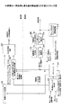
E−UTRAにおける上りリンクの無線アクセスに使用されるSC−FDMAについて、図1を参照して説明する。システムで使用可能な周波数帯域は、複数のリソースブロックに分割され、リソースブロックの各々は1以上のサブキャリアを含む。ユーザ装置(UE: User Equipment)には1以上のリソースブロックが割り当てられる。周波数スケジューリングでは、ユーザ装置から報告される下りパイロットチャネルのリソースブロック毎の受信信号品質又はチャネル状態情報(CQI: Channel Quality Indicator)に応じて、チャネル状態の良好な端末に優先的にリソースブロックを割り当てることにより、システム全体の伝送効率又はスループットを向上させる。また、使用可能な周波数ブロックを所定の周波数ホッピングパターンに従って変更する周波数ホッピングも適用されることが検討されている。 SC-FDMA used for uplink radio access in E-UTRA will be described with reference to FIG. The frequency band usable in the system is divided into a plurality of resource blocks, and each resource block includes one or more subcarriers. One or more resource blocks are allocated to a user equipment (UE: User Equipment). In frequency scheduling, resource blocks are preferentially allocated to terminals having good channel states according to the received signal quality or channel state information (CQI: Channel Quality Indicator) for each resource block of the downlink pilot channel reported from the user apparatus. As a result, the transmission efficiency or throughput of the entire system is improved. In addition, it is considered that frequency hopping in which usable frequency blocks are changed according to a predetermined frequency hopping pattern is also applied.
図1において、異なるハッチングは異なるユーザ装置に割り当てられる時間・周波数リソースを示す。UE2は、広めの帯域が割り当てられていたが、次のサブフレームでは狭い帯域が割り当てられる。各ユーザ装置は、重複しないように異なる周波数帯域が割り当てられる。 In FIG. 1, different hatching indicates time / frequency resources allocated to different user apparatuses. UE 2 has been assigned a wider band, but a narrow band is assigned in the next subframe. Each user apparatus is assigned a different frequency band so as not to overlap.
SC−FDMAでは、セル内の各ユーザ装置は、異なる時間・周波数リソースを用いて送信する。このようにして、セル内のユーザ装置間の直交が実現される。この時間・周波数リソースの最小の単位をリソースユニット(RU: Resource Unit)と呼ぶ。SC−FDMAでは、連続する周波数を割り当てることにより、低PAPR(peak−to−average power ratio)のシングルキャリア伝送が実現される。SC−FDMAでは、割り当てる時間・周波数リソースは、基地局装置のスケジューラが、各ユーザ装置の伝搬状況、送るべきデータのQoS(Quality of Service)に基づいて決定する。ここで、QoSにはデータレート、所要の誤り率、遅延が含まれる。このように、伝搬状況のよい時間・周波数リソースを各ユーザ装置に割り当てることによりスループットを増大できる。 In SC-FDMA, each user apparatus in a cell transmits using different time / frequency resources. In this way, orthogonality between user apparatuses in the cell is realized. This minimum unit of time / frequency resources is called a resource unit (RU). In SC-FDMA, low PAPR (peak-to-average power ratio) single carrier transmission is realized by assigning continuous frequencies. In SC-FDMA, the time / frequency resource to be allocated is determined by the scheduler of the base station apparatus based on the propagation status of each user apparatus and the QoS (Quality of Service) of data to be transmitted. Here, the QoS includes a data rate, a required error rate, and a delay. Thus, throughput can be increased by allocating time / frequency resources with good propagation conditions to each user apparatus.
各基地局装置は、割り当てる時間・周波数リソースを個々に行っているため、あるセルで割り当てられた帯域が、隣のセルで割り当てられる帯域の一部と重なる場合が生じる。このように、隣のセルで割り当てられる帯域の一部が重なる場合には、干渉が生じ互いに劣化する。
上述したように、E−UTRAにおける上りリンクの無線アクセスでは、周波数ホッピングを適用することが検討されている。 As described above, in uplink radio access in E-UTRA, it is considered to apply frequency hopping.
しかしながら、周波数ホッピングが適用される場合の周波数ホッピングパターンや、ホッピングを行う場合に、使用するリソースユニットを通知するシグナリングについては検討されていない。 However, the frequency hopping pattern when frequency hopping is applied and the signaling for notifying the resource unit to be used when hopping is performed have not been studied.
そこで、本発明は、上述した課題に鑑み、その目的は、E−UTRAが適用されるシステムにおいて、上りリンクにおいて、周波数ホッピングを適用させることができる基地局装置を提供することにある。 In view of the above-described problems, an object of the present invention is to provide a base station apparatus capable of applying frequency hopping in the uplink in a system to which E-UTRA is applied.
本ユーザ装置は、
ユーザ装置の割り当て単位としてリソースユニットが規定されるとともに、リソースユニットの時間領域の長さがスロットであり、周波数領域において、システム帯域内に複数のリソースユニットが配置されるとともに、かつ時間領域において、サブフレームにふたつのスロットが配置され、所定のユーザ装置に対して、サブフレームの1番目のスロットとサブフレームの2番目のスロットのそれぞれにおいて、互いに異なった周波数のリソースユニットにデータをマッピングする変調部と、
前記変調部においてマッピングしたデータを送信する送信部と
を備え、
前記変調部では、ふたつのスロットのそれぞれに対して、周波数領域において連続した2つ以上のリソースユニットを含んだリソースユニットグループが、システム帯域内に2つ以上規定され、1番目のスロットにおいて前記所定のユーザ装置にマッピングすべきリソースユニットを含むリソースユニットグループと、2番目のスロットにおいて前記所定のユーザ装置にマッピングすべきリソースユニットを含むリソースユニットグループとは、一定数のリソースユニットグループ分の周波数だけ異なってマッピングがなされ、
前記変調部は、各リソースユニットブロックに含まれるリソースユニットに対し、各リソースユニットブロック内において、低周波数側から高周波数側へ向かって1から順に大きくなるような、該リソースユニットを識別するためのインデックスを付与しており、(リソースユニットブロックにおけるリソースユニットの最大インデックス)+1−(1番目のスロットでのリソースユニットブロックにおいて前記所定のユーザ装置にマッピングしたリソースユニットのインデックス)に対応するリソースユニットを前記2番目のスロットでのリソースユニットブロックにおけるリソースユニットとして、前記所定のユーザ装置にマッピングする。
本送信方法は、
ユーザ装置の割り当て単位としてリソースユニットが規定されるとともに、リソースユニットの時間領域の長さがスロットであり、周波数領域において、システム帯域内に複数のリソースユニットが配置されるとともに、かつ時間領域において、サブフレームにふたつのスロットが配置され、所定のユーザ装置に対して、サブフレームの1番目のスロットとサブフレームの2番目のスロットのそれぞれにおいて、互いに異なった周波数のリソースユニットにデータをマッピングするステップと、
マッピングしたデータを送信するステップとを備え、
前記マッピングするステップでは、ふたつのスロットのそれぞれに対して、周波数領域において連続した2つ以上のリソースユニットを含んだリソースユニットグループが、システム帯域内に2つ以上規定され、1番目のスロットにおいて前記所定のユーザ装置にマッピングすべきリソースユニットを含むリソースユニットグループと、2番目のスロットにおいて前記所定のユーザ装置にマッピングすべきリソースユニットを含むリソースユニットグループとは、一定数のリソースユニットグループ分の周波数だけ異なってマッピングがなされ、
前記マッピングするステップは、各リソースユニットブロックに含まれるリソースユニットに対し、各リソースユニットブロック内において、低周波数側から高周波数側へ向かって1から順に大きくなるような、該リソースユニットを識別するためのインデックスを付与しており、(リソースユニットブロックにおけるリソースユニットの最大インデックス)+1−(1番目のスロットでのリソースユニットブロックにおいて前記所定のユーザ装置にマッピングしたリソースユニットのインデックス)に対応するリソースユニットを前記2番目のスロットでのリソースユニットブロックにおけるリソースユニットとして、前記所定のユーザ装置にマッピングする。
本通信システムは、
ユーザ装置と、
基地局装置と
を備え、
前記ユーザ装置は、
ユーザ装置の割り当て単位としてリソースユニットが規定されるとともに、リソースユニットの時間領域の長さがスロットであり、周波数領域において、システム帯域内に複数のリソースユニットが配置されるとともに、かつ時間領域において、サブフレームにふたつのスロットが配置され、所定のユーザ装置に対して、サブフレームの1番目のスロットとサブフレームの2番目のスロットのそれぞれにおいて、互いに異なった周波数のリソースユニットにデータをマッピングする変調部と、
前記変調部においてマッピングしたデータを送信する送信部と
を備え、
前記変調部では、ふたつのスロットのそれぞれに対して、周波数領域において連続した2つ以上のリソースユニットを含んだリソースユニットグループが、システム帯域内に2つ以上規定され、1番目のスロットにおいて前記所定のユーザ装置にマッピングすべきリソースユニットを含むリソースユニットグループと、2番目のスロットにおいて前記所定のユーザ装置にマッピングすべきリソースユニットを含むリソースユニットグループとは、一定数のリソースユニットグループ分の周波数だけ異なってマッピングがなされ、
前記変調部は、各リソースユニットブロックに含まれるリソースユニットに対し、各リソースユニットブロック内において、低周波数側から高周波数側へ向かって1から順に大きくなるような、該リソースユニットを識別するためのインデックスを付与しており、(リソースユニットブロックにおけるリソースユニットの最大インデックス)+1−(1番目のスロットでのリソースユニットブロックにおいて前記所定のユーザ装置にマッピングしたリソースユニットのインデックス)に対応するリソースユニットを前記2番目のスロットでのリソースユニットブロックにおけるリソースユニットとして、前記所定のユーザ装置にマッピングする。
This user device
A resource unit is defined as an allocation unit of the user apparatus, the length of the time domain of the resource unit is a slot, a plurality of resource units are arranged in the system band in the frequency domain, and in the time domain, two slots are located in the sub-frame, for a given user equipment, in each of the second slot of the first slot and the subframe of a subframe and maps the data to a resource unit of different frequencies from each other modulation And
A transmitter for transmitting the data mapped in the modulator, and
In the modulation unit, for each of the two slots, the resource unit group that includes two or more resource units that are continuous in the frequency domain, defined two or more in the system band, Oite the first slot wherein the resource unit group including a resource unit to be mapped to a predetermined user device, and the resource unit group including a second slot resource unit to be mapped to Oite the predetermined user devices, a certain number of resource unit group The mapping is done differently by the frequency of minutes ,
The modulator is configured to identify a resource unit included in each resource unit block such that the resource unit increases in order from 1 toward the high frequency side from the low frequency side in each resource unit block. An index is assigned, and a resource unit corresponding to (maximum index of resource unit in resource unit block) + 1− (index of resource unit mapped to the predetermined user apparatus in the resource unit block in the first slot) The resource unit block in the second slot is mapped to the predetermined user device as a resource unit .
This transmission method is
A resource unit is defined as an allocation unit of the user apparatus, the length of the time domain of the resource unit is a slot, a plurality of resource units are arranged in the system band in the frequency domain, and in the time domain, two slots are located in the sub-frame, for a given user equipment, in each of the second slot of the first slot and the subframe of a subframe and maps the data to a resource unit of different frequencies from each other step When,
Sending the mapped data,
In the mapping step, for each of the two slots, two or more resource unit groups including two or more resource units that are continuous in the frequency domain are defined in the system band, and the first slot is assigned. a resource unit group including a resource unit to be mapped to the predetermined user devices have a resource unit group including a resource unit to be mapped to the predetermined user devices Oite the second slot, a certain number of resource units Mapping is done differently by the frequency of the group ,
The mapping step identifies resource units included in each resource unit block such that the resource units increase in order from 1 toward the high frequency side from the low frequency side in each resource unit block. The resource unit corresponding to (the maximum index of the resource unit in the resource unit block) + 1− (the index of the resource unit mapped to the predetermined user apparatus in the resource unit block in the first slot) Are mapped to the predetermined user equipment as resource units in the resource unit block in the second slot .
This communication system
A user device;
A base station device, and
The user equipment is
A resource unit is defined as an allocation unit of the user apparatus, the length of the time domain of the resource unit is a slot, a plurality of resource units are arranged in the system band in the frequency domain, and in the time domain, two slots are located in the sub-frame, for a given user equipment, in each of the second slot of the first slot and the subframe of a subframe and maps the data to a resource unit of different frequencies from each other modulation And
A transmitter for transmitting the data mapped in the modulator, and
In the modulation unit, for each of the two slots, the resource unit group that includes two or more resource units that are continuous in the frequency domain, defined two or more in the system band, Oite the first slot wherein the resource unit group including a resource unit to be mapped to a predetermined user device, and the resource unit group including a second slot resource unit to be mapped to Oite the predetermined user devices, a certain number of resource unit group The mapping is done differently by the frequency of minutes ,
The modulator is configured to identify a resource unit included in each resource unit block such that the resource unit increases in order from 1 toward the high frequency side from the low frequency side in each resource unit block. An index is assigned, and a resource unit corresponding to (maximum index of resource unit in resource unit block) + 1− (index of resource unit mapped to the predetermined user apparatus in the resource unit block in the first slot) The resource unit block in the second slot is mapped to the predetermined user device as a resource unit .
本発明の実施例によれば、E−UTRAが適用されるシステムにおいて、上りリンクにおいて、周波数ホッピングを適用させることができる基地局装置を実現することができる。 According to the embodiment of the present invention, it is possible to realize a base station apparatus capable of applying frequency hopping in the uplink in a system to which E-UTRA is applied.
以下、本発明の実施例を、図面を参照しつつ説明する。実施例を説明するための全図において、同一機能を有するものは同一符号を用い、繰り返しの説明は省略する。 Embodiments of the present invention will be described below with reference to the drawings. In all the drawings for explaining the embodiments, the same reference numerals are used for those having the same function, and repeated explanation is omitted.
図2を参照しながら、本発明の実施例に係るユーザ装置及び基地局装置を有する無線通信システムについて説明する。ユーザ装置は移動局装置とも呼ばれる。 A radio communication system having a user apparatus and a base station apparatus according to an embodiment of the present invention will be described with reference to FIG. The user apparatus is also called a mobile station apparatus.
無線通信システム1000は、例えばEvolved UTRA and UTRAN(別名:Long Term Evolution,或いは,Super 3G)が適用されるシステムである。無線通信システム1000は、基地局装置(eNB: eNode B)200m(2001、2002、2003、・・・、200m、mはm>0の整数)と、基地局装置200mと通信する複数のユーザ装置100n(1001、1002、1003、・・・100n、nはn>0の整数)とを備える。基地局装置200mは、上位局、例えばアクセスゲートウェイ装置300と接続され、アクセスゲートウェイ装置300は、コアネットワーク400と接続される。ユーザ装置100nはセル50k(501、502、・・・、50k、kはk>0の整数)のいずれかにおいて基地局装置200mとEvolved UTRA and UTRANにより通信を行う。
The
ここで、ユーザ装置100nには、基地局装置200mのいずれかと通信チャネルを確立し、通信状態にあるものと、基地局装置200mのいずれとも通信チャネルを確立しておらず、無通信状態にあるものが混在するものとする。 Here, the user apparatus 100 n, and establish a communication channel with any of the base station apparatus 200 m, and those in communication, not to establish with any communication channel of the base station apparatus 200 m, no communication It is assumed that things in a state are mixed.
基地局装置200mは、同期信号を送信する。ユーザ装置100nは、セル50k(501、502、503、・・・50k、kはk>0の整数)のいずれかに位置し、電源立ち上げ時、あるいは、通信中の間欠受信時等において、該同期信号に基づいて、自ユーザ装置にとって無線品質が良好なセルを検出するセルサーチを行う。すなわち、ユーザ装置100nは、同期信号を用いてシンボルタイミングとフレームタイミングとを検出し、かつ、セルID(セルIDから生成されるセル固有のスクランブルコード)またはセルIDの集合(セルIDグループと呼ぶ)などのセル固有の制御情報の検出を行う。 The base station device 200 m transmits a synchronization signal. The user apparatus 100 n is located in any of the cells 50 k (50 1 , 50 2 , 50 3 ,... 50 k , k is an integer of k> 0), and is turned on or in communication At the time of intermittent reception or the like, based on the synchronization signal, a cell search for detecting a cell having good radio quality for the user apparatus is performed. That is, the user apparatus 100 n detects the symbol timing and the frame timing using the synchronization signal, and uses a cell ID (cell-specific scramble code generated from the cell ID) or a set of cell IDs (cell ID group and Cell-specific control information is detected.
ここで、セルサーチは、ユーザ装置100nが通信状態にある場合と無通信状態にある場合の両方で行われる。例えば、通信状態におけるセルサーチとしては、同じ周波数のセルを検出するためのセルサーチや異なる周波数のセルを検出するためのセルサーチ等がある。また、無線通信状態におけるセルサーチとしては、例えば、電源立ち上げ時のセルサーチや待ち受け時のセルサーチ等がある。 Here, the cell search is performed both when the user apparatus 100 n is in a communication state and when it is in a no-communication state. For example, the cell search in the communication state includes a cell search for detecting a cell having the same frequency and a cell search for detecting a cell having a different frequency. In addition, cell search in the wireless communication state includes, for example, cell search at power-on and cell search at standby.
以下、基地局装置200m(2001、2002、2003、・・・200m)については、同一の構成、機能、状態を有するので、以下では特段の断りがない限り基地局装置200mとして説明を進める。以下、ユーザ装置100n(1001、1002、1003、・・・100n)については、同一の構成、機能、状態を有するので、以下では特段の断りがない限りユーザ装置100nとして説明を進める。以下、セル50k(501、502、503、・・・50k)については、同一の構成、機能、状態を有するので、以下では特段の断りがない限りセル50kとして説明を進める。 Hereinafter, since the base station apparatus 200 m (200 1 , 200 2 , 200 3 ,... 200 m ) has the same configuration, function, and state, the base station apparatus 200 m will be described below unless otherwise specified. As the explanation proceeds. Hereinafter, since the user apparatus 100 n (100 1 , 100 2 , 100 3 ,... 100 n ) has the same configuration, function, and state, the following description will be given as the user apparatus 100 n unless otherwise specified. To proceed. Hereinafter, since the cells 50 k (50 1 , 50 2 , 50 3 ,... 50 k ) have the same configuration, function, and state, the following description will be given as the cell 50 k unless otherwise specified. .
無線通信システム1000は、無線アクセス方式として、下りリンクについてはOFDM(直交周波数分割多元接続)、上りリンクについてはSC−FDMA(シングルキャリア−周波数分割多元接続)が適用される。上述したように、OFDMは、周波数帯域を複数の狭い周波数帯域(サブキャリア)に分割し、各周波数帯上にデータを載せて伝送を行う方式である。SC−FDMAは、周波数帯域を分割し、複数のユーザ装置間で異なる周波数帯域を用いて伝送することで、ユーザ装置間の干渉を低減することができる伝送方式である。
ここで、Evolved UTRA and UTRANにおける通信チャネルについて説明する。 Here, communication channels in Evolved UTRA and UTRAN will be described.
下りリンクについては、各ユーザ装置100nで共有して使用される物理下りリンク共有チャネル(PDSCH: Physical Downlink Shared Channel)と、LTE用の下り制御チャネルとが用いられる。下りリンクでは、LTE用の下り制御チャネルにより、物理下りリンク共有チャネルにマッピングされるユーザ装置の情報やトランスポートフォーマットの情報、物理上りリンク共有チャネルにマッピングされるユーザ装置の情報やトランスポートフォーマットの情報、物理上りリンク共有チャネルの送達確認情報などが通知され、物理下りリンク共有チャネルによりユーザデータが伝送される。 For the downlink, a physical downlink shared channel (PDSCH) shared by each user apparatus 100 n and a downlink control channel for LTE are used. In the downlink, the user equipment information and the transport format information mapped to the physical downlink shared channel, the user equipment information and the transport format mapped to the physical uplink shared channel by the LTE downlink control channel Information, acknowledgment information of the physical uplink shared channel, etc. are notified, and user data is transmitted through the physical downlink shared channel.
また、下りリンクにおいて、基地局装置200mは、ユーザ装置100nがセルサーチを行うための同期信号を送信する。 In the downlink, the base station apparatus 200 m transmits a synchronization signal for the user apparatus 100 n to perform cell search.
上りリンクについては、各ユーザ装置100nで共有して使用される物理上りリンク共有チャネル(PUSCH:Physical Uplink Shared Channel)と、LTE用の上り制御チャネルとが用いられる。尚、上り制御チャネルには、物理上りリンク共有チャネルと時間多重されるチャネルと、周波数多重されるチャネルの2種類がある。上りリンクでは、LTE用の上り制御チャネルにより、下りリンクにおける物理共有チャネルのスケジューリング、適応変復調・符号化(AMC: Adaptive Modulation and Coding)に用いるための下りリンクの品質情報(CQI: Channel Quality Indicator)及び下りリンクの物理共有チャネルの送達確認情報(HARQ ACK information)が伝送される。上りリンクチャネルは、物理上りリンク共有チャネルとLTE用の上りリンク制御チャネルとを指す。尚、LTE用の上りリンク制御チャネルには、物理上りリンク共有チャネルと時間多重されるチャネルと、周波数多重されるチャネルの2種類がある。図3に、LTE用の上りリンク制御チャネルのマッピングを示す。 For the uplink, a physical uplink shared channel (PUSCH) shared by each user apparatus 100 n and an uplink control channel for LTE are used. There are two types of uplink control channels: a physical uplink shared channel and a time multiplexed channel, and a frequency multiplexed channel. In the uplink, downlink quality information (CQI: Channel Quality Indicator) to be used for physical shared channel scheduling in the downlink, adaptive modulation and coding (AMC: Adaptive Modulation and Coding) by the uplink control channel for LTE. And acknowledgment information (HARQ ACK information) of the downlink physical shared channel is transmitted. The uplink channel indicates a physical uplink shared channel and an uplink control channel for LTE. There are two types of uplink control channels for LTE: channels that are time multiplexed with physical uplink shared channels and channels that are frequency multiplexed. FIG. 3 shows mapping of the uplink control channel for LTE.
尚、図3において、周波数多重されている上りリンク制御チャネルは、サブフレーム内の2つのサブフレーム間で、マッピングされる位置が異なる(周波数ホッピングが行われる)。図3において、500は物理上りリンク共有チャネルを示し、510は物理上りリンク共有チャネルと周波数多重される場合を示し、520は物理上りリンク共有チャネルと時間多重される場合を示す。 In FIG. 3, the frequency-multiplexed uplink control channel is mapped at different positions (frequency hopping is performed) between two subframes in the subframe. In FIG. 3, 500 indicates a physical uplink shared channel, 510 indicates a case where the frequency is multiplexed with the physical uplink shared channel, and 520 indicates a case where the time is multiplexed with the physical uplink shared channel.
上りリンクでは、LTE用の上りリンク制御チャネルにより、下りリンクにおける共有チャネルのスケジューリング、適応変復調・符号化(AMCS: Adaptive Modulation and Coding Scheme)に用いるための下りリンクの品質情報(CQI: Channel Quality Indicator)及び下りリンクの物理下りリンク共有チャネルの送達確認情報(HARQ ACK information)が伝送される。また、物理上りリンク共有チャネルによりユーザデータが伝送される。 In the uplink, downlink quality information (CQI: Channel Quality Indicator) to be used for downlink shared channel scheduling, adaptive modulation and coding scheme (AMCS) by an uplink control channel for LTE. ) And acknowledgment information (HARQ ACK information) of the physical downlink shared channel of the downlink. Further, user data is transmitted through the physical uplink shared channel.
尚、物理上りリンク共有チャネルにマッピングされるトランスポートチャネルは上りリンク共有チャネル(UL−SCH: Uplink Shared Channel)である。すなわち、ユーザデータは、UL−SCHにマッピングされる。 Note that the transport channel mapped to the physical uplink shared channel is an uplink shared channel (UL-SCH: Uplink Shared Channel). That is, user data is mapped to UL-SCH.
物理上りリンク制御チャネルでは、CQIや送達確認情報に加えて、上りリンクの共有チャネルのリソース割り当てを要求するスケジューリング要求(Scheduling Request)や、パーシステントスケジューリング(Persistent Scheduling)におけるリリース要求(Release Request)等が送信されてもよい。ここで、上りリンクの共有チャネルのリソース割り当てとは、あるサブフレームの物理下りリンク制御チャネルを用いて、後続のサブフレームにおいて上りリンクの共有チャネルを用いて通信を行ってよいことを基地局装置がユーザ装置に通知することを意味する。 In the physical uplink control channel, in addition to CQI and acknowledgment information, a scheduling request (Scheduling Request) for requesting resource allocation of an uplink shared channel, a release request (Release Request) in persistent scheduling (Release Request), etc. May be sent. Here, the uplink shared channel resource allocation means that communication may be performed using an uplink shared channel in a subsequent subframe using a physical downlink control channel of a certain subframe. Means to notify the user device.
本実施例に係る無線通信システムでは、上りリンクにおいて周波数ホッピングが適用される。周波数ホッピングでは、使用可能な周波数ブロックが所定の周波数ホッピングパターンに従って変更される。 In the radio communication system according to the present embodiment, frequency hopping is applied in the uplink. In frequency hopping, usable frequency blocks are changed according to a predetermined frequency hopping pattern.
図4に示すように、ユーザ装置100nには、上りリンクにおいて周波数ホッピングが適用される場合には、1リソースユニット(RU: Resource Unit)を単位として割り当てられる。図4において、横軸は周波数、縦軸は時間を示す。例えば、1リソースユニットの帯域幅は180kHzであり、1スロット長は、0.5msecである。1サブフレームには、2スロットが含まれる。 As shown in FIG. 4, when frequency hopping is applied in the uplink, the user apparatus 100 n is allocated in units of one resource unit (RU: Resource Unit). In FIG. 4, the horizontal axis represents frequency and the vertical axis represents time. For example, the bandwidth of one resource unit is 180 kHz, and the length of one slot is 0.5 msec. One subframe includes two slots.
例えば、周波数ホッピングが適用されるユーザ装置は、システム帯域の両端の周波数帯域が割り当てられる。このようにすることにより、周波数ホッピングが適用されるユーザ装置の間の周波数ダイバーシチ効果を大きくできる。また、システム帯域の両端の周波数帯域以外の周波数帯域には、ローカライズドFDMAが適用されるユーザ装置に割り当てられるが、このローカライズドFDMAが適用されるユーザ装置にとって、シングルキャリア伝送との整合性を高くできる。 For example, a user apparatus to which frequency hopping is applied is assigned a frequency band at both ends of the system band. By doing in this way, the frequency diversity effect between the user apparatuses to which frequency hopping is applied can be increased. In addition, frequency bands other than the frequency bands at both ends of the system band are allocated to user apparatuses to which localized FDMA is applied. For user apparatuses to which this localized FDMA is applied, consistency with single carrier transmission is ensured. Can be high.
本実施例に係る基地局装置200では、ユーザ装置の伝搬情報及びトラヒックタイプに基づいて、当該ユーザ装置に対して周波数ホッピングを適用するか否かが決定される。ユーザ装置の伝搬情報には、該ユーザ装置の移動速度が含まれる。例えば、周波数ホッピングを適用することにより、周波数ダイバーシチの効果を期待できるユーザ装置に対しては、周波数ホッピングを適用すると判断する。具体的には、高速で移動するユーザ装置、音声パケット(VoIP)のように周期的に小さなサイズのデータを送信するユーザ装置に対して、周波数ホッピングを適用すると判断する。周波数ホッピングが適用されるユーザ装置に対して、周波数ホッピングを適用して上りリンクの信号を送信することが通知される。 In the base station apparatus 200 according to the present embodiment, whether to apply frequency hopping to the user apparatus is determined based on the propagation information and traffic type of the user apparatus. The propagation information of the user device includes the moving speed of the user device. For example, by applying frequency hopping, it is determined that frequency hopping is applied to a user apparatus that can expect the effect of frequency diversity. Specifically, it is determined that frequency hopping is applied to a user apparatus that moves at high speed and a user apparatus that periodically transmits data of a small size such as a voice packet (VoIP). The user equipment to which the frequency hopping is applied is notified that the uplink signal is transmitted by applying the frequency hopping.
基地局装置200は、周波数ホッピングを適用すると判断されたユーザ装置に対しては、スケジューリング処理において、1リソースユニットを単位として、1サブフレームにおいては、各スロットで、異なる帯域のリソースユニットが割り当てられる。すなわち、各サブフレームにおいて、時間方向で、前半のリソースユニット(前半のスロット)と後半のリソースユニット(後半のスロット)ではその帯域が異なる。 The base station apparatus 200 allocates resource units of different bands in each slot in one subframe in a scheduling process for a user apparatus determined to apply frequency hopping in a scheduling process. . That is, in each subframe, the bandwidths of the first resource unit (first slot) and the second resource unit (second slot) differ in the time direction.
また、スケジューリングの結果、決定されたリソースユニットの情報は、アップリンク スケジューリング グラント(Uplink Scheduling Grant)で通知される。例えば、各サブフレームにおいて、前半のリソースユニットと、該前半のリソースユニットに対する周波数方向におけるシフト量が通知される。 Also, information on the resource unit determined as a result of scheduling is notified by an uplink scheduling grant (Uplink Scheduling Grant). For example, in each subframe, the first half resource unit and the shift amount in the frequency direction with respect to the first half resource unit are notified.
次に、本実施例に係る基地局装置200mについて、図5を参照して説明する。 Next, the base station apparatus 200 m according to the present embodiment will be described with reference to FIG.
本実施例に係る基地局装置200mは、OFDM信号生成部202と、上り割り当て許可信号送信用制御信号生成部204と、復調用RS生成部206と、同期検出・チャネル推定部208と、チャネル復号部210と、コヒーレント検波部212と、各ユーザの上りリンクチャネル状態推定部214と、スケジューラ216と、周波数ホッピング決定部218とを備える。OFDM信号生成部202及び上り割り当て許可信号送信用制御信号生成部204は送信部を構成し、復調用RS生成部206、同期検出・チャネル推定部208、チャネル復号部210、コヒーレント検波部212、各ユーザの上りリンクチャネル状態推定部214、スケジューラ216及び周波数ホッピング決定部218は受信部を構成する。
The base station apparatus 200 m according to the present embodiment includes an OFDM
ユーザ装置100nから送信された上りリンクのチャネルは、同期検出・チャネル推定部208、コヒーレント検波部212及び各ユーザの上りリンクチャネル状態推定部214に入力される。
The uplink channel transmitted from the user apparatus 100 n is input to the synchronization detection /
同期検出・チャネル推定部208は、入力された受信信号の同期検出を行い、受信タイミングを推定し、後述する復調用RS生成部206により入力された復調用RS(Demodulation Reference signal)に基づいて、チャネル推定を行い、その結果をコヒーレント検波部212に入力する。
The synchronization detection /
コヒーレント検波部212は、チャネル推定結果及び後述するスケジューラ216により入力された割り当てた周波数と帯域幅に基づいて、受信信号に対しコヒーレント検波を行い、復調後の受信信号をチャネル復号部210に入力する。チャネル復号部210は、入力された復調後の受信信号を復号し、スケジューラ216により入力される割り当てたユーザ番号に対応する再生データ信号を生成する。生成された再生データ信号はネットワークに送信される。
The
また、各ユーザの上りリンクチャネル状態推定部214は、入力された受信信号に基づいて、チャネル状態を推定し、各ユーザ装置の上りリンクチャネル状態推定結果をスケジューラ216に入力する。
Moreover, the uplink channel
周波数ホッピング決定部218には、各ユーザ装置の伝搬情報及びトラフィックタイプが入力される。周波数ホッピング決定部226は、入力された各ユーザ装置の伝搬情報及びトラフィックタイプに基づいて、当該ユーザ装置100nに周波数ホッピングを適用するか否かを判断する。例えば、ユーザ装置の伝搬情報、具体的には、ユーザ装置の移動速度が所定の閾値以上である場合及び/又はトラヒックタイプが音声パケット(VoIP)のように周期的に送信される小さなサイズのデータである場合には、周波数ホッピングを適用することを決定する。一方、ユーザ装置の移動速度が所定の閾値未満及びトラヒックタイプが音声パケット(VoIP)のように周期的に送信される小さなサイズのデータ以外である場合には、周波数ホッピングを適用しないことを決定する。周波数ホッピング決定部226は、周波数ホッピングを適用することを決定した場合、当該ユーザ装置に対して周波数ホッピングを適用することをスケジューラ216及び上り割り当て許可信号送信用制御信号生成部204に通知する。
The frequency
スケジューラ216は、入力された各ユーザ装置の上りリンクチャネル状態推定結果及び各ユーザ装置のQoS、例えば要求データレート、バッファ状態、所要誤り率、遅延などに基づいて、例えば周波数スケジューリングを行い、割り当てた周波数と帯域幅を上り割り当て許可信号送信用制御信号生成部204及びコヒーレント検波部212に入力し、割り当てたユーザ番号を上り割り当て許可信号送信用制御信号生成部204及びチャネル復号部210に入力する。ここで、スケジューリングとは、所定のサブフレームにおいて共有チャネルを用いてパケットデータの送信を行うユーザ装置を選別する処理である。その後、スケジューリングにおいて選別されたユーザ装置が送信するパケットデータに関する変調方式や符号化率、データサイズを決定する処理が行われる。変調方式、符号化率、データサイズの決定は、例えば、ユーザ装置から上りリンクにおいて送信されるサウンディング用リファレンス信号のSIRに基づいて行われる。さらに、スケジューリングにおいて選別されたユーザ装置が送信するパケットデータの送信に用いられるリソースユニットを決定する。リソースユニットの決定は、例えば、ユーザ装置から上りリンクにおいて送信するサウンディング用リファレンス信号のSIRに基づいて行われる。
The
そして、上り割り当て許可信号送信用制御信号生成部204において、上述したスケジューリング処理、伝送フォーマットの選択処理、周波数リソースの割り当て処理により決定される、物理上りリンク共有チャネルを用いて通信を行うユーザ(ユーザ装置)のIDや、そのユーザデータのトランスポートフォーマットの情報、すなわち、データサイズ、変調方式に関する情報や、上りリンクのリソースユニットの割り当て情報、上りリンクの共有チャネルの送信電力に関する情報等が含まれる、UL Scheduling Grantが生成される。ここで、上りリンクのリソースユニットとは、周波数リソースに相当し、リソースブロックとも呼ばれる。
Then, in the uplink allocation permission signal transmission control
また、スケジューラ216は、周波数ホッピング決定部218により、周波数ホッピングを適用することを通知された場合、当該ユーザ装置に対しては、1リソースユニットを単位として、1サブフレームにおいては、スロット毎に異なる帯域のリソースユニットが割り当てられる。
In addition, when the frequency
この周波数ホッピングが適用されるユーザ装置に対しては、上り割り当て許可信号送信用制御信号生成部204は、当該ユーザ装置に対し、周波数ホッピングが適用されることを通知する。この通知は、アップリンク スケジューリング グラントによりしてもよいし、上位レイヤの制御信号で通知するようにしてもよい。アップリンク スケジューリング グラントは、サブフレーム毎に通知されるので、上位レイヤにより通知するよりも高速に周波数ホッピングに切り替えることができる。
For the user apparatus to which this frequency hopping is applied, the uplink assignment permission signal transmission control
また、上り割り当て許可信号送信用制御信号生成部204は、周波数ホッピングが適用される場合には、各サブフレームにおいて、前半のリソースユニットと、該前半のリソースユニットに対する周波数方向におけるシフト量の情報が含まれる、アップリンク スケジューリング グラントを生成する。例えば、周波数方向の一方から、リソースユニットに対してインデックスが付された場合、各サブフレームにおいて、前半のリソースユニットのインデックスと、該前半のリソースユニットに対するインデックスのシフト量の情報が含まれる、アップリンク スケジューリング グラントを生成する。ユーザ装置100nは、前半のリソースユニットに対する周波数方向におけるシフト量により、後半のスロットにおけるリソースユニットを特定する。
In addition, when frequency hopping is applied, the uplink allocation permission signal transmission control
復調用RS生成部206は、復調用RSを生成し、同期検出・チャネル推定部208に入力する。
The demodulation
上り割り当て許可信号送信用制御信号生成部208は、入力された割り当てた周波数と帯域幅及び割り当てユーザ番号を含む制御信号(上り割り当て許可信号送信用制御信号)を生成し、OFDM信号生成部204に入力する。この制御信号には、例えばアップリンク スケジューリング グラントが含まれる。
The uplink allocation permission signal transmission control
OFDM信号生成部204は、該制御信号を含むOFDM信号を生成し送信無線機に入力する。その結果、下りリンクの制御チャネルによりスケジューリングの対象となるユーザ装置に通知される。
The OFDM
OFDM信号生成部202は、上述した制御チャネル以外に、他の下りリンクチャネル、例えば下りリファレンスシグナル、データチャネル、ページングチャネルなどを含むOFDM信号を生成し送信無線機に入力する。その結果、下りリンクチャネルがユーザ装置に送信される。
The OFDM
次に、本実施例に係るユーザ装置100nについて、図6を参照して説明する。 Next, the user apparatus 100 n according to the present embodiment will be described with reference to FIG.
本実施例に係るユーザ装置100nは、OFDM信号復調部102と、上り割り当て許可信号復調・復号部104と、その他の制御信号、データ信号の復調・復号部106と、復調用RS生成部108と、チャネル符号化部110と、データ変調部112と、SC−FDMA変調部114とを備える。OFDM信号復調部102、上り割り当て許可信号復調・復号部104及びその他の制御信号、データ信号の復調・復号部106は受信部を構成し、復調用RS生成部108、チャネル符号化部110、データ変調部112及びSC−FDMA変調部114は送信部を構成する。
The user apparatus 100 n according to the present embodiment includes an OFDM
ユーザ装置100nは、上り割り当て許可信号の復号結果において、割り当てユーザ番号が自ユーザ装置100nを指示した場合のみ送信信号の生成及び送信を行う。 The user apparatus 100 n generates and transmits a transmission signal only when the allocated user number indicates the own user apparatus 100 n in the decoding result of the uplink allocation permission signal.
基地局装置200mからの受信信号は、OFDM信号復調部102に入力され、復調処理が行われ、上り割り当て許可信号送信用制御信号は上り割り当て許可信号復調・復号部104に入力され、上り割り当て許可信号送信用制御信号以外の制御信号、データ信号は、その他の制御信号、データ信号の復調・復号部106に入力される。
The received signal from the base station apparatus 200 m is input to the OFDM
上り割り当て許可信号復調・復号部104は、入力された上り割り当て許可信号の復調・復号処理を行い、基地局装置200から、周波数ホッピングを適用することが通知された場合には、その周波数ホッピング適用通知をSC−FDMA変調部114に入力する。また、上り割り当て許可信号復調・復号部104は、割り当てられたリソースユニットを示す情報をSC−FDMA変調部114に入力する。例えば、上り割り当て許可信号復調・復号部104は、各サブフレームにおいて、前半のスロットと、該前半のスロットに対する周波数方向におけるシフト量の情報をSC−FDMA変調部114に入力する。
Uplink assignment permission signal demodulation /
復調用RS生成部108は、復調用RSを生成し、SC−FDMA変調部114に入力する。
The demodulation
一方、ユーザデータは、チャネル符号化部110においてチャネル符号化が行われ、データ変調部112においてデータ変調が行われ、SC−FDMA変調部114に入力される。
On the other hand, the user data is subjected to channel coding in the
SC−FDMA変調部(DFT−spread OFDM)114は、入力された復調用RS、変調されたユーザデータを割り当てられたリソースユニットに基づいて変調し、送信信号を出力する。例えば、SC−FDMA変調部(DFT−spread OFDM)114は、各サブフレームにおいて、前半のスロットと、該前半のスロットに対する周波数方向におけるシフト量の情報に基づいて、前半のスロットに対する周波数方向におけるシフト量から、後半のスロットにおけるリソースユニットを特定する。その結果、周波数ホッピングを適用すると判断されたユーザ装置は、1リソースユニットを単位として、1サブフレームにおいては、スロット毎に異なる帯域のリソースユニットによりデータ送信を行う。 The SC-FDMA modulation unit (DFT-spread OFDM) 114 modulates the input demodulation RS and the modulated user data based on the allocated resource unit, and outputs a transmission signal. For example, the SC-FDMA modulation unit (DFT-spread OFDM) 114 performs shift in the frequency direction for the first half slot in each subframe based on information on the first half slot and the shift amount in the frequency direction for the first half slot. The resource unit in the latter half slot is specified from the quantity. As a result, a user apparatus that is determined to apply frequency hopping performs data transmission using resource units of different bands for each slot in one subframe, with one resource unit as a unit.
次に、本発明の他の実施例に係る基地局装置及びユーザ装置が適用される無線通信システムについて説明する。 Next, a radio communication system to which a base station apparatus and a user apparatus according to another embodiment of the present invention are applied will be described.
本実施例に係る無線通信システム、基地局装置及びユーザ装置の構成は、図2、図5及び図6を参照して説明した構成と同様である。 The configurations of the radio communication system, the base station apparatus, and the user apparatus according to the present embodiment are the same as those described with reference to FIGS.
本実施例では、上述した実施例と同様に、基地局装置200は、周波数ホッピングを適用すると判断されたユーザ装置に対しては、スケジューリング処理において、1リソースユニットを単位として、1サブフレームにおいては、スロット毎に異なる帯域のリソースユニットを割り当てる。この場合、本実施例では、各サブフレームにおいて、時間方向における前半のリソースユニットに対する後半のリソースユニットの周波数方向のシフト量が予め決定されている。例えば、周波数方向の一方から、リソースユニットに対してインデックスが付された場合、シフト量はリソースユニットのインデックス(番号)のシフト量により指定される。具体的には、シフト量として+21が指定された場合には、図7に示すように、前半のリソースユニット番号に対して21だけ加算されたリソースユニットが後半のリソースユニットなる。このシフト量は、ユーザ装置のサポートできる周波数帯域と対応させて予め仕様化しておくようにしてもよいし、上位レイヤで通知するようにしてもよい。このように構成することにより、サブフレーム毎に、一定の周波数だけ離れた周波数で送信されるため、一定の周波数ダイバーシチ効果を得ることができる。 In the present embodiment, as in the above-described embodiment, the base station apparatus 200 performs, in a scheduling process, a user unit determined to apply frequency hopping in one resource unit as a unit in one subframe. Allocate resource units with different bandwidths for each slot. In this case, in this embodiment, in each subframe, the amount of shift in the frequency direction of the latter half resource unit with respect to the first half resource unit in the time direction is determined in advance. For example, when an index is attached to a resource unit from one side in the frequency direction, the shift amount is specified by the shift amount of the index (number) of the resource unit. Specifically, when +21 is designated as the shift amount, as shown in FIG. 7, the resource unit obtained by adding 21 to the first half resource unit number becomes the second half resource unit. This shift amount may be specified in advance corresponding to a frequency band that can be supported by the user apparatus, or may be notified in an upper layer. With this configuration, transmission is performed at a frequency separated by a certain frequency for each subframe, so that a certain frequency diversity effect can be obtained.
また、スケジューリングの結果、決定されたリソースユニットの情報は、アップリンク スケジューリング グラント(Uplink Scheduling Grant)で通知される。シフト量は、予め決定されているか、上位レイヤにより通知されているので、各サブフレームにおいて、前半のリソースユニットのインデックスが通知される。 Also, information on the resource unit determined as a result of scheduling is notified by an uplink scheduling grant (Uplink Scheduling Grant). Since the shift amount is determined in advance or is notified by an upper layer, the index of the first half resource unit is notified in each subframe.
具体的には、スケジューラ216は、周波数ホッピング決定部226により、周波数ホッピングを適用することを通知された場合、当該ユーザ装置に対しては、前半のリソースユニットを割り当てるスケジューリングが行われる。この場合、上りリンクでは、SC−FDMAが適用されるので、連続するリソースユニットを割り当てる場合には、後半のスロットにおいて、割り当てられるリソースユニットが不連続にならないように、前半のリソースユニットが割り当てられる。言い換えれば、連続するリソースユニットが割り当てられる。
Specifically, when the frequency hopping determination unit 226 is notified that the
この周波数ホッピングが適用されるユーザ装置に対しては、上り割り当て許可信号送信用制御信号生成部204は、各サブフレームにおいて、前半のリソースユニットの情報、具体的には前半のリソースユニットのインデックスが含まれる、アップリンク スケジューリング グラントを生成する。
For a user apparatus to which this frequency hopping is applied, the uplink allocation permission signal transmission control
次に、本発明の他の実施例に係る基地局装置及びユーザ装置が適用される無線通信システムについて説明する。 Next, a radio communication system to which a base station apparatus and a user apparatus according to another embodiment of the present invention are applied will be described.
本実施例に係る無線通信システム、基地局装置及びユーザ装置の構成は、図2、図5及び図6を参照して説明した構成と同様である。 The configurations of the radio communication system, the base station apparatus, and the user apparatus according to the present embodiment are the same as those described with reference to FIGS.
本実施例では、上述した実施例と同様に、基地局装置200は、周波数ホッピングを適用すると判断されたユーザ装置に対しては、スケジューリング処理において、1リソースユニットを単位として、1サブフレームにおいては、スロット毎に異なる帯域のリソースユニットを割り当てる。この場合、本実施例では、各サブフレームにおいて、前半のリソースユニットと後半のリソースユニットとの対応が予め決定される。例えば、周波数方向の一方から、リソースユニットに対してインデックスが付された場合、図8に示すように、前半のリソースユニットのインデックスがk(kは、0≦kの整数)である場合、後半のリソースユニットは、(リソースユニットの最大インデックス)−kにより表される。この対応は、予め仕様化しておくようにしてもよいし、上位レイヤで通知するようにしてもよい。このように構成することにより、後半のスロットにおいて、割り当てられるリソースユニットが不連続になることがないため、シングルキャリアの特性を特別な制御を行うことなく維持できる。 In the present embodiment, as in the above-described embodiment, the base station apparatus 200 performs, in a scheduling process, a user unit determined to apply frequency hopping in one resource unit as a unit in one subframe. Allocate resource units with different bandwidths for each slot. In this case, in this embodiment, in each subframe, the correspondence between the first half resource unit and the second half resource unit is determined in advance. For example, when the resource unit is indexed from one side in the frequency direction, as shown in FIG. 8, when the index of the first half resource unit is k (k is an integer of 0 ≦ k), the second half Are represented by (maximum index of resource unit) −k. This correspondence may be specified in advance or may be notified in an upper layer. With this configuration, the resource units to be allocated do not become discontinuous in the latter half of the slot, so that the single carrier characteristics can be maintained without special control.
また、スケジューリングの結果、決定されたリソースユニットの情報は、アップリンク スケジューリング グラント(Uplink Scheduling Grant)で通知される。前半のリソースユニットと後半のリソースユニットとの対応は、予め決定されているか、上位レイヤにより通知されているので、各サブフレームにおいて、前半のリソースユニットの情報、具体的には前半のリソースユニットのインデックスが通知される。 Also, information on the resource unit determined as a result of scheduling is notified by an uplink scheduling grant (Uplink Scheduling Grant). The correspondence between the resource units in the first half and the resource units in the second half is determined in advance or notified by the upper layer. Therefore, in each subframe, information on the resource units in the first half, specifically, the resource units in the first half The index is notified.
具体的には、スケジューラ216は、周波数ホッピング決定部218により、周波数ホッピングを適用することが通知された場合、当該ユーザ装置に対しては、前半のリソースユニットを割り当てるスケジューリングが行われる。
Specifically, when the frequency
この周波数ホッピングが適用されるユーザ装置に対しては、上り割り当て許可信号送信用制御信号生成部204は、各サブフレームにおいて、前半のリソースユニットの情報、具体的には前半のリソースユニットのインデックスが含まれる、アップリンク スケジューリング グラントを生成する。
For a user apparatus to which this frequency hopping is applied, the uplink allocation permission signal transmission control
次に、本発明の他の実施例に係る基地局装置及びユーザ装置が適用される無線通信システムについて説明する。 Next, a radio communication system to which a base station apparatus and a user apparatus according to another embodiment of the present invention are applied will be described.
本実施例に係る無線通信システム、基地局装置及びユーザ装置の構成は、図2、図5及び図6を参照して説明した構成と同様である。 The configurations of the radio communication system, the base station apparatus, and the user apparatus according to the present embodiment are the same as those described with reference to FIGS.
本実施例では、リソースユニットグループ(RUG: Resource Unit Group)が定義される。リソースユニットグループには連続する複数のリソースユニットが含まれる。 In this embodiment, a resource unit group (RUG) is defined. A resource unit group includes a plurality of consecutive resource units.
本実施例では、上述した実施例と同様に、基地局装置200は、周波数ホッピングを適用すると判断されたユーザ装置に対しては、スケジューリング処理において、1リソースユニットを単位として、1サブフレームにおいては、スロット毎に異なる帯域のリソースユニットを割り当てる。この場合、本実施例では、各サブフレームにおいて、時間方向における前半のリソースユニットグループに対する後半のリソースユニットグループの周波数方向のシフト量が予め決定されている。例えば、周波数方向の一方から、リソースユニットグループに対してインデックスが付された場合、シフト量はリソースユニットグループのインデックス(番号)のシフト量により指定される。具体的には、シフト量として+5が指定された場合には、図9に示すように、前半のリソースユニットグループ#1に対して5だけ加算されたリソースユニットグループ#6が後半のリソースユニットグループとなる。
In the present embodiment, as in the above-described embodiment, the base station apparatus 200 performs, in a scheduling process, a user unit determined to apply frequency hopping in one resource unit as a unit in one subframe. Allocate resource units with different bandwidths for each slot. In this case, in this embodiment, in each subframe, the shift amount in the frequency direction of the second half resource unit group with respect to the first half resource unit group in the time direction is determined in advance. For example, when the resource unit group is indexed from one side in the frequency direction, the shift amount is specified by the shift amount of the index (number) of the resource unit group. Specifically, when +5 is designated as the shift amount, as shown in FIG. 9, the resource
さらに、前半のリソースユニットグループに含まれるリソースユニットと後半のリソースユニットグループに含まれるリソースユニットとの対応が予め決定される。例えば、リソースユニットグループ毎に、周波数方向の一方から、リソースユニットに対してインデックスが付された場合、具体的には、図10に示すように、前半のリソースユニットグループにおけるリソースユニットのインデックスをi(iは、0<iの整数であり、i≦リソースユニットグループに含まれるリソースユニット数)とした場合、後半のリソースユニットは、(後半のリソースユニットグループにおけるリソースユニットのインデックスの最大値)+1−iにより表される。この対応は、予め仕様化しておくようにしてもよいし、上位レイヤで通知するようにしてもよい。このように構成することにより、一定の周波数だけ離れたリソースユニットグループに含まれる周波数で送信されるため、一定の周波数ダイバーシチ効果を得ることができるとともに、後半のスロットにおいて、割り当てられるリソースユニットが不連続になることがないため、シングルキャリアの特性を特別な制御を行うことなく維持できる。 Furthermore, the correspondence between the resource units included in the first half resource unit group and the resource units included in the second half resource unit group is determined in advance. For example, when an index is assigned to a resource unit from one side in the frequency direction for each resource unit group, specifically, the index of the resource unit in the first half resource unit group is set to i as shown in FIG. When i is an integer of 0 <i and i ≦ the number of resource units included in the resource unit group, the latter resource unit is (the maximum value of the index of the resource unit in the latter resource unit group) +1. -I. This correspondence may be specified in advance or may be notified in an upper layer. With this configuration, transmission is performed at a frequency included in a resource unit group that is separated by a certain frequency, so that a certain frequency diversity effect can be obtained, and the allocated resource units are not allocated in the latter half slot. Since it is not continuous, the characteristics of the single carrier can be maintained without special control.
また、スケジューリングの結果、決定されたリソースユニットの情報、具体的にはリソースユニットのインデックスは、アップリンク スケジューリング グラント(Uplink Scheduling Grant)で通知される。前半のリソースユニットグループと後半のリソースユニットグループとの対応及び前半のリソースユニットグループに含まれるリソースユニットと後半のリソースユニットグループに含まれるリソースユニットとの対応は、予め決定されているか、上位レイヤにより通知されているので、各サブフレームにおいて、前半のリソースユニットグループの情報と、該リソースユニットグループにおけるリソースユニットの情報が通知される。具体的には、前半のリソースユニットグループのインデックスと、該リソースユニットグループにおけるリソースユニットのインデックスが通知される。 Further, information on the resource unit determined as a result of scheduling, specifically, an index of the resource unit, is notified by an uplink scheduling grant (Uplink Scheduling Grant). The correspondence between the resource unit group in the first half and the resource unit group in the second half and the correspondence between the resource unit included in the resource unit group in the first half and the resource unit contained in the resource unit group in the second half are determined in advance or by higher layers. Since the notification is made, in each subframe, information on the first half of the resource unit group and information on the resource unit in the resource unit group are notified. Specifically, the index of the first half resource unit group and the index of the resource unit in the resource unit group are notified.
スケジューラ216は、周波数ホッピング決定部226により、周波数ホッピングを適用することを通知された場合、当該ユーザ装置に対しては、前半のリソースユニットを割り当てるスケジューリングが行われる。
When the
この周波数ホッピングが適用されるユーザ装置に対しては、上り割り当て許可信号送信用制御信号生成部204は、各サブフレームにおいて、割り当てる前半のリソースユニットが含まれる前半のリソースユニットグループのインデックスと、該リソースユニットグループにおける割り当てる前半のリソースユニットのインデックスの情報が含まれる、アップリンク スケジューリング グラントを生成する。
For a user apparatus to which this frequency hopping is applied, the uplink allocation permission signal transmission control
次に、本発明の他の実施例に係る基地局装置及びユーザ装置が適用される無線通信システムについて説明する。 Next, a radio communication system to which a base station apparatus and a user apparatus according to another embodiment of the present invention are applied will be described.
本実施例に係る無線通信システムの構成は、図2を参照して説明した構成と同様である。 The configuration of the wireless communication system according to the present embodiment is the same as the configuration described with reference to FIG.
本実施例に係る基地局装置200は、図11に示すように、図5を参照して説明した基地局装置において、スケジューラ216及びOFDM信号生成部202と接続された報知チャネル生成部220を備える点で異なる。
As shown in FIG. 11, the base station apparatus 200 according to the present embodiment includes a broadcast
本実施例では、スケジューラ216は、スケジューリングにより、割り当てたリソースユニットの割り当て情報を、報知チャネル生成部220に入力する。
In this embodiment, the
報知チャネル生成部220は、入力された割り当てたリソースユニットの割り当て情報を、物理下りリンク共有チャネルで送信される報知チャネルで送信する。この物理下りリンク共有チャネルで送信される報知チャネルは、ダイナミック報知チャネルとも呼ばれる。
The broadcast
このようにすることにより、周波数ホッピングを適用することを決定した場合、当該ユーザ装置に対して周波数ホッピングを適用することを1ビットのみで通知できる。この場合、UL Scheduling Grantには、周波数ホッピングを適用するかしないかを示す1ビットが含まれる。 In this way, when it is determined to apply frequency hopping, it is possible to notify the user apparatus of applying frequency hopping with only one bit. In this case, the UL Scheduling Grant includes 1 bit indicating whether to apply frequency hopping.
本実施例に係るユーザ装置100は、図12に示すように、図6を参照して説明したユーザ装置において、OFDM信号復号部102及びSC−FDMA変調部114と接続された報知チャネル復調・復号部116を備える点で異なる。
As shown in FIG. 12, the user apparatus 100 according to the present embodiment, in the user apparatus described with reference to FIG. 6, broadcast channel demodulation / decoding connected to the OFDM
基地局装置200mからの受信信号は、OFDM信号復調部102に入力され、復調処理が行われ、上り割り当て許可信号送信用制御信号は上り割り当て許可信号復調・復号部104に入力され、報知チャネルは報知チャネル復調・復号部116に入力され、上り割り当て許可信号送信用制御信号及び報知チャネル以外の制御信号、データ信号は、その他の制御信号、データ信号の復調・復号部106に入力される。
The received signal from the base station apparatus 200 m is input to the OFDM
報知チャネル復調・復号部116は、入力された報知チャネルの復調・復号処理を行い、割り当てられたリソースユニットの割り当て情報をSC−FDMA変調部114に入力する。
Broadcast channel demodulation /
上述した実施例においては、図13に示すように、周波数ホッピングが適用されるユーザ装置はシステム帯域の両端の周波数帯域が割り当てられ、システム帯域の両端の周波数帯域以外の周波数帯域にはローカライズドFDMAが適用されるユーザ装置に割り当てられる場合について説明したが、図14に示すように、周波数ホッピングが適用されるユーザ装置にシステム帯域の両端の周波数帯域だけではなく、システム帯域の両端の周波数帯域以外の周波数帯域も割り当てるようにしてもよい。このようにすることにより、周波数ホッピングが適用されるユーザ装置数が多い場合でも、周波数領域のスケジューリングの効果を得ることができる。 In the above-described embodiment, as shown in FIG. 13, the user equipment to which frequency hopping is applied is assigned frequency bands at both ends of the system band, and localized FDMA is assigned to frequency bands other than the frequency bands at both ends of the system band. However, as shown in FIG. 14, not only the frequency band at both ends of the system band but also the frequency band at both ends of the system band is applied to the user apparatus to which frequency hopping is applied. May also be assigned. By doing in this way, even when the number of user apparatuses to which frequency hopping is applied is large, the effect of scheduling in the frequency domain can be obtained.
尚、上述した実施例においては、Evolved UTRA and UTRAN(別名:Long Term Evolution,或いは,Super 3G)が適用されるシステムにおける例を記載したが、本発明に係る基地局装置は、上りリンクにおいてFDMA、例えばSC−FDMA方式を用いる全てのシステムにおいて適用することが可能である。 In the above-described embodiment, an example in a system to which Evolved UTRA and UTRAN (also known as Long Term Evolution or Super 3G) is applied has been described. However, the base station apparatus according to the present invention can perform FDMA in uplink. For example, the present invention can be applied to all systems using the SC-FDMA system.
説明の便宜上、発明の理解を促すため具体的な数値例を用いて説明されるが、特に断りのない限り、それらの数値は単なる一例に過ぎず適切な如何なる値が使用されてよい。 For convenience of explanation, specific numerical examples will be described to facilitate understanding of the invention. However, unless otherwise specified, these numerical values are merely examples, and any appropriate value may be used.
以上、本発明は特定の実施例を参照しながら説明されてきたが、各実施例は単なる例示に過ぎず、当業者は様々な変形例、修正例、代替例、置換例等を理解するであろう。説明の便宜上、本発明の実施例に係る装置は機能的なブロック図を用いて説明されたが、そのような装置はハードウエアで、ソフトウエアで又はそれらの組み合わせで実現されてもよい。本発明は上記実施例に限定されず、本発明の精神から逸脱することなく、様々な変形例、修正例、代替例、置換例等が包含される。 Although the present invention has been described above with reference to specific embodiments, each embodiment is merely an example, and those skilled in the art will understand various variations, modifications, alternatives, substitutions, and the like. I will. For convenience of explanation, an apparatus according to an embodiment of the present invention has been described using a functional block diagram, but such an apparatus may be realized by hardware, software, or a combination thereof. The present invention is not limited to the above-described embodiments, and various variations, modifications, alternatives, substitutions, and the like are included without departing from the spirit of the present invention.
50k(501、502、・・・、50k) セル
100n(1001、1002、1003、・・・、100n) ユーザ装置
102 OFDM信号復調部
104 上り割り当て許可信号復調・復号部
106 その他の制御信号、データ信号の復調・復号部
108 復調用RS生成部
110 チャネル符号化部
112 データ変調部
114 SC−FDMA変調部
116 報知チャネル復調・復号部
200m(2001、2002、2003、・・・、200m) 基地局装置
202 OFDM信号生成部
204 上り割り当て許可信号送信用制御信号生成部
206 復調用RS生成部
208 同期検出・チャネル推定部
210 チャネル復号部
212 コヒーレント検波部
214 各ユーザの上りリンクチャネル状態推定部
216 スケジューラ
218 周波数ホッピング決定部
220 報知チャネル生成部
400 コアネットワーク
500 物理上りリンク共有チャネル
510 上りリンク制御チャネル
520 上りリンク制御チャネル
50 k (50 1 , 50 2 ,..., 50 k ) Cell 100 n (100 1 , 100 2 , 100 3 ,..., 100 n )
Claims (5)
前記変調部においてマッピングしたデータを送信する送信部と
を備え、
前記変調部では、ふたつのスロットのそれぞれに対して、周波数領域において連続した2つ以上のリソースユニットを含んだリソースユニットグループが、システム帯域内に2つ以上規定され、1番目のスロットにおいて前記所定のユーザ装置にマッピングすべきリソースユニットを含むリソースユニットグループと、2番目のスロットにおいて前記所定のユーザ装置にマッピングすべきリソースユニットを含むリソースユニットグループとは、一定数のリソースユニットグループ分の周波数だけ異なってマッピングがなされ、
前記変調部は、各リソースユニットブロックに含まれるリソースユニットに対し、各リソースユニットブロック内において、低周波数側から高周波数側へ向かって1から順に大きくなるような、該リソースユニットを識別するためのインデックスを付与しており、(リソースユニットブロックにおけるリソースユニットの最大インデックス)+1−(1番目のスロットでのリソースユニットブロックにおいて前記所定のユーザ装置にマッピングしたリソースユニットのインデックス)に対応するリソースユニットを前記2番目のスロットでのリソースユニットブロックにおけるリソースユニットとして、前記所定のユーザ装置にマッピングすることを特徴とするユーザ装置。 A resource unit is defined as an allocation unit of the user apparatus, the length of the time domain of the resource unit is a slot, a plurality of resource units are arranged in the system band in the frequency domain, and in the time domain, two slots are located in the sub-frame, for a given user equipment, in each of the second slot of the first slot and the subframe of a subframe and maps the data to a resource unit of different frequencies from each other modulation And
A transmitter for transmitting the data mapped in the modulator, and
In the modulation unit, for each of the two slots, the resource unit group that includes two or more resource units that are continuous in the frequency domain, defined two or more in the system band, Oite the first slot wherein the resource unit group including a resource unit to be mapped to a predetermined user device, and the resource unit group including a second slot resource unit to be mapped to Oite the predetermined user devices, a certain number of resource unit group The mapping is done differently by the frequency of minutes ,
The modulator is configured to identify a resource unit included in each resource unit block such that the resource unit increases in order from 1 toward the high frequency side from the low frequency side in each resource unit block. An index is assigned, and a resource unit corresponding to (maximum index of resource unit in resource unit block) + 1− (index of resource unit mapped to the predetermined user apparatus in the resource unit block in the first slot) The user device is mapped to the predetermined user device as a resource unit in a resource unit block in the second slot .
前記変調部は、前記受信部において受けつけた情報をもとに、マッピングを実行することを特徴とする請求項1に記載のユーザ装置。 In one subframe definitive time domain, shows a first resource unit and is predetermined relationship with the second resource unit corresponding to the second slot, the first resource unit corresponding to the first slot A receiver that receives information from the base station device;
The user apparatus according to claim 1, wherein the modulation unit executes mapping based on information received by the reception unit.
マッピングしたデータを送信するステップとを備え、
前記マッピングするステップでは、ふたつのスロットのそれぞれに対して、周波数領域において連続した2つ以上のリソースユニットを含んだリソースユニットグループが、システム帯域内に2つ以上規定され、1番目のスロットにおいて前記所定のユーザ装置にマッピングすべきリソースユニットを含むリソースユニットグループと、2番目のスロットにおいて前記所定のユーザ装置にマッピングすべきリソースユニットを含むリソースユニットグループとは、一定数のリソースユニットグループ分の周波数だけ異なってマッピングがなされ、
前記マッピングするステップは、各リソースユニットブロックに含まれるリソースユニットに対し、各リソースユニットブロック内において、低周波数側から高周波数側へ向かって1から順に大きくなるような、該リソースユニットを識別するためのインデックスを付与しており、(リソースユニットブロックにおけるリソースユニットの最大インデックス)+1−(1番目のスロットでのリソースユニットブロックにおいて前記所定のユーザ装置にマッピングしたリソースユニットのインデックス)に対応するリソースユニットを前記2番目のスロットでのリソースユニットブロックにおけるリソースユニットとして、前記所定のユーザ装置にマッピングすることを特徴とする送信方法。 A resource unit is defined as an allocation unit of the user apparatus, the length of the time domain of the resource unit is a slot, a plurality of resource units are arranged in the system band in the frequency domain, and in the time domain, two slots are located in the sub-frame, for a given user equipment, in each of the second slot of the first slot and the subframe of a subframe and maps the data to a resource unit of different frequencies from each other step When,
Sending the mapped data,
In the mapping step, for each of the two slots, two or more resource unit groups including two or more resource units that are continuous in the frequency domain are defined in the system band, and the first slot is assigned. a resource unit group including a resource unit to be mapped to the predetermined user devices have a resource unit group including a resource unit to be mapped to the predetermined user devices Oite the second slot, a certain number of resource units Mapping is done differently by the frequency of the group ,
The mapping step identifies resource units included in each resource unit block such that the resource units increase in order from 1 toward the high frequency side from the low frequency side in each resource unit block. The resource unit corresponding to (the maximum index of the resource unit in the resource unit block) + 1− (the index of the resource unit mapped to the predetermined user apparatus in the resource unit block in the first slot) As a resource unit in a resource unit block in the second slot is mapped to the predetermined user apparatus .
基地局装置と
を備え、
前記ユーザ装置は、
ユーザ装置の割り当て単位としてリソースユニットが規定されるとともに、リソースユニットの時間領域の長さがスロットであり、周波数領域において、システム帯域内に複数のリソースユニットが配置されるとともに、かつ時間領域において、サブフレームにふたつのスロットが配置され、所定のユーザ装置に対して、サブフレームの1番目のスロットとサブフレームの2番目のスロットのそれぞれにおいて、互いに異なった周波数のリソースユニットにデータをマッピングする変調部と、
前記変調部においてマッピングしたデータを送信する送信部と
を備え、
前記変調部では、ふたつのスロットのそれぞれに対して、周波数領域において連続した2つ以上のリソースユニットを含んだリソースユニットグループが、システム帯域内に2つ以上規定され、1番目のスロットにおいて前記所定のユーザ装置にマッピングすべきリソースユニットを含むリソースユニットグループと、2番目のスロットにおいて前記所定のユーザ装置にマッピングすべきリソースユニットを含むリソースユニットグループとは、一定数のリソースユニットグループ分の周波数だけ異なってマッピングがなされ、
前記変調部は、各リソースユニットブロックに含まれるリソースユニットに対し、各リソースユニットブロック内において、低周波数側から高周波数側へ向かって1から順に大きくなるような、該リソースユニットを識別するためのインデックスを付与しており、(リソースユニットブロックにおけるリソースユニットの最大インデックス)+1−(1番目のスロットでのリソースユニットブロックにおいて前記所定のユーザ装置にマッピングしたリソースユニットのインデックス)に対応するリソースユニットを前記2番目のスロットでのリソースユニットブロックにおけるリソースユニットとして、前記所定のユーザ装置にマッピングすることを特徴とする通信システム。 A user device;
A base station device, and
The user equipment is
A resource unit is defined as an allocation unit of the user apparatus, the length of the time domain of the resource unit is a slot, a plurality of resource units are arranged in the system band in the frequency domain, and in the time domain, two slots are located in the sub-frame, for a given user equipment, in each of the second slot of the first slot and the subframe of a subframe and maps the data to a resource unit of different frequencies from each other modulation And
A transmitter for transmitting the data mapped in the modulator, and
In the modulation unit, for each of the two slots, the resource unit group that includes two or more resource units that are continuous in the frequency domain, defined two or more in the system band, Oite the first slot wherein the resource unit group including a resource unit to be mapped to a predetermined user device, and the resource unit group including a second slot resource unit to be mapped to Oite the predetermined user devices, a certain number of resource unit group The mapping is done differently by the frequency of minutes ,
The modulator is configured to identify a resource unit included in each resource unit block such that the resource unit increases in order from 1 toward the high frequency side from the low frequency side in each resource unit block. An index is assigned, and a resource unit corresponding to (maximum index of resource unit in resource unit block) + 1− (index of resource unit mapped to the predetermined user apparatus in the resource unit block in the first slot) The communication system , wherein the resource unit is mapped to the predetermined user apparatus as a resource unit in the resource unit block in the second slot .
Priority Applications (16)
| Application Number | Priority Date | Filing Date | Title |
|---|---|---|---|
| JP2007211598A JP4728301B2 (en) | 2007-08-14 | 2007-08-14 | User apparatus, transmission method, and communication system |
| CN200880110779A CN101822120A (en) | 2007-08-14 | 2008-08-13 | base station device |
| KR1020107003507A KR101471439B1 (en) | 2007-08-14 | 2008-08-13 | Base station device |
| EP15160270.3A EP2919491B1 (en) | 2007-08-14 | 2008-08-13 | User equipment for uplink frequency hopping |
| AU2008287803A AU2008287803B2 (en) | 2007-08-14 | 2008-08-13 | Base station |
| PCT/JP2008/064540 WO2009022706A1 (en) | 2007-08-14 | 2008-08-13 | Base station device |
| HUE15160270A HUE030325T2 (en) | 2007-08-14 | 2008-08-13 | User equipment for uplink frequency hopping |
| US12/672,584 US8428019B2 (en) | 2007-08-14 | 2008-08-13 | Base station |
| CN201210394344.6A CN102916724B (en) | 2007-08-14 | 2008-08-13 | User device, transmission method and communication system |
| EP08827462.6A EP2190126A4 (en) | 2007-08-14 | 2008-08-13 | BASE STATION DEVICE |
| MX2010001642A MX2010001642A (en) | 2007-08-14 | 2008-08-13 | BASE STATION DEVICE. |
| RU2010106282/07A RU2469499C2 (en) | 2007-08-14 | 2008-08-13 | Basic station |
| BRPI0815418 BRPI0815418A2 (en) | 2007-08-14 | 2008-08-13 | Base Station |
| CA 2695525 CA2695525A1 (en) | 2007-08-14 | 2008-08-13 | Base station |
| RU2012134989/07A RU2502220C1 (en) | 2007-08-14 | 2012-08-16 | User terminal, communication method and communication system |
| US13/791,134 US8699443B2 (en) | 2007-08-14 | 2013-03-08 | Base station |
Applications Claiming Priority (1)
| Application Number | Priority Date | Filing Date | Title |
|---|---|---|---|
| JP2007211598A JP4728301B2 (en) | 2007-08-14 | 2007-08-14 | User apparatus, transmission method, and communication system |
Related Child Applications (1)
| Application Number | Title | Priority Date | Filing Date |
|---|---|---|---|
| JP2011090459A Division JP5226099B2 (en) | 2011-04-14 | 2011-04-14 | User device, transmission method, communication system |
Publications (3)
| Publication Number | Publication Date |
|---|---|
| JP2009049541A JP2009049541A (en) | 2009-03-05 |
| JP2009049541A5 JP2009049541A5 (en) | 2010-07-15 |
| JP4728301B2 true JP4728301B2 (en) | 2011-07-20 |
Family
ID=40350758
Family Applications (1)
| Application Number | Title | Priority Date | Filing Date |
|---|---|---|---|
| JP2007211598A Active JP4728301B2 (en) | 2007-08-14 | 2007-08-14 | User apparatus, transmission method, and communication system |
Country Status (12)
| Country | Link |
|---|---|
| US (2) | US8428019B2 (en) |
| EP (2) | EP2919491B1 (en) |
| JP (1) | JP4728301B2 (en) |
| KR (1) | KR101471439B1 (en) |
| CN (2) | CN102916724B (en) |
| AU (1) | AU2008287803B2 (en) |
| BR (1) | BRPI0815418A2 (en) |
| CA (1) | CA2695525A1 (en) |
| HU (1) | HUE030325T2 (en) |
| MX (1) | MX2010001642A (en) |
| RU (2) | RU2469499C2 (en) |
| WO (1) | WO2009022706A1 (en) |
Cited By (1)
| Publication number | Priority date | Publication date | Assignee | Title |
|---|---|---|---|---|
| JP2011188505A (en) * | 2011-04-14 | 2011-09-22 | Ntt Docomo Inc | User apparatus |
Families Citing this family (27)
| Publication number | Priority date | Publication date | Assignee | Title |
|---|---|---|---|---|
| GB2446197A (en) * | 2007-02-05 | 2008-08-06 | Nec Corp | Frequency-hopping method and mobile communication system |
| CN102160413B (en) * | 2008-09-22 | 2014-09-03 | 夏普株式会社 | Wireless communication system, base station device, mobile station device, and wireless communication method |
| JPWO2010106783A1 (en) | 2009-03-16 | 2012-09-20 | パナソニック株式会社 | Wireless communication apparatus and wireless communication method |
| KR101653022B1 (en) * | 2009-05-29 | 2016-08-31 | 파나소닉 인텔렉츄얼 프로퍼티 코포레이션 오브 아메리카 | Terminal apparatus, base station apparatus, transmission method, receiving method, and integrated circuit |
| WO2011016252A1 (en) * | 2009-08-07 | 2011-02-10 | パナソニック株式会社 | Radio base station and radio communication method |
| CN102045789B (en) | 2009-10-16 | 2013-05-08 | 中兴通讯股份有限公司 | Frequency physics resource scheduling method and system based on frequency hopping |
| GB2476488A (en) | 2009-12-23 | 2011-06-29 | Nec Corp | Allocating physical resource blocks to a user device for transmitting uplink data |
| DK2526643T3 (en) | 2010-01-18 | 2018-08-13 | Ericsson Telefon Ab L M | Radio base station and user device and methods therein |
| KR101403154B1 (en) | 2010-04-27 | 2014-06-03 | 후지쯔 가부시끼가이샤 | Wireless communication method, wireless base station, mobile terminal, and wireless communication system |
| CN102387589B (en) * | 2010-08-31 | 2014-04-09 | 电信科学技术研究院 | Method and device for resource allocation |
| KR20120100078A (en) * | 2011-03-03 | 2012-09-12 | 삼성전자주식회사 | Apparatus and method for supportting frequency hopping in broadcasting communication system |
| JP5616284B2 (en) * | 2011-05-02 | 2014-10-29 | 株式会社Nttドコモ | Base station apparatus, mobile terminal apparatus, communication system, and communication method |
| GB201114079D0 (en) | 2011-06-13 | 2011-09-28 | Neul Ltd | Mobile base station |
| GB2492052B (en) | 2011-06-13 | 2015-06-24 | Neul Ltd | Interference mitigation |
| GB2491222B (en) * | 2012-02-29 | 2013-07-10 | Renesas Mobile Corp | Channel quality |
| CN109152063A (en) | 2012-12-17 | 2019-01-04 | 华为技术有限公司 | A kind of distribution method of carrier wave, user equipment and base station |
| WO2014190537A1 (en) | 2013-05-31 | 2014-12-04 | 华为技术有限公司 | Information transmission method, base station, user equipment and system |
| JP2015032947A (en) * | 2013-08-01 | 2015-02-16 | ネッツエスアイ東洋株式会社 | Automatic meter reading system |
| CN105517158A (en) * | 2014-09-24 | 2016-04-20 | 中兴通讯股份有限公司 | Wireless resource distribution processing method and device |
| US10454739B2 (en) * | 2015-01-23 | 2019-10-22 | Texas Instruments Incorporated | Transmission scheme for SC-FDMA with two DFT-precoding stages |
| CN106357579B (en) * | 2015-07-17 | 2020-02-18 | 中兴通讯股份有限公司 | A method for using spectrum resources in an orthogonal frequency division multiplexing system and a corresponding base station |
| EP3334074A4 (en) | 2015-08-07 | 2019-07-31 | Mitsubishi Electric Corporation | TRANSMITTER APPARATUS, RECEIVER APPARATUS, TRANSMISSION METHOD, AND RECEIVING METHOD |
| CN107359927B (en) * | 2017-06-27 | 2020-07-28 | 广西师范大学 | A Relay Selection Method for EH Energy Harvesting Collaborative Communication Network |
| MX2020005010A (en) * | 2017-11-17 | 2020-08-27 | Ntt Docomo Inc | User terminal and wireless communication method. |
| EP4021107A4 (en) * | 2019-08-23 | 2023-04-26 | Ntt Docomo, Inc. | WIRELESS COMMUNICATION TERMINAL AND METHOD |
| CN117098233A (en) * | 2019-09-16 | 2023-11-21 | 中兴通讯股份有限公司 | Data transmission methods, devices and systems |
| WO2021168709A1 (en) * | 2020-02-26 | 2021-09-02 | Oppo广东移动通信有限公司 | Methods and apparatuses for reporting and receiving csi, terminal device, and network device |
Family Cites Families (13)
| Publication number | Priority date | Publication date | Assignee | Title |
|---|---|---|---|---|
| GB2318252A (en) * | 1996-10-09 | 1998-04-15 | Motorola Ltd | Channel Allocation in a Cellular Radio Network |
| JPH11243382A (en) * | 1998-02-25 | 1999-09-07 | Sony Corp | Physical channel assignment method and transmission device |
| AR014805A1 (en) * | 1998-04-03 | 2001-03-28 | Ericsson Telefon Ab L M | METHOD FOR OPERATING A MOBILE UNIT TO USE IT IN A CELLULAR SYSTEM WITH JUMP DISPLACEMENT BETWEEN NON-COORDINATED FREQUENCIES, MOBILE UNIT AND CELLULAR SYSTEM WITH JUMP DISPLACEMENT BETWEEN NON-COORDINATED FREQUENCIES |
| FI106329B (en) * | 1998-10-23 | 2001-01-15 | Nokia Networks Oy | Frequency hopping method and base station |
| CN1234254C (en) * | 2003-07-18 | 2005-12-28 | 大唐移动通信设备有限公司 | Radio resources layout method and device |
| KR100929103B1 (en) * | 2004-08-17 | 2009-11-30 | 삼성전자주식회사 | Frequency allocating apparatus and method for supporting high speed forward packet data service in orthogonal frequency multiplexing mobile communication system |
| US8537760B2 (en) * | 2004-12-17 | 2013-09-17 | Samsung Electronics Co., Ltd | Method and system for dynamic hybrid multiple access in an OFDM-based wireless network |
| WO2006121302A1 (en) * | 2005-05-13 | 2006-11-16 | Samsung Electronics Co., Ltd. | Method and apparatus for indexing physical channels in an ofdma system |
| GB2429605B (en) * | 2005-08-24 | 2008-06-04 | Ipwireless Inc | Apparatus and method for communicating signalling information |
| KR100881967B1 (en) * | 2006-01-06 | 2009-02-04 | 삼성전자주식회사 | Method and apparatus for transmitting / receiving reverse information in monocarrier frequency division multiple access system |
| JP4363406B2 (en) | 2006-02-07 | 2009-11-11 | トヨタ自動車株式会社 | Air-fuel ratio control device for internal combustion engine |
| CN100571285C (en) * | 2006-07-03 | 2009-12-16 | 中兴通讯股份有限公司 | An identification method and device for multi-level remote wireless equipment |
| US8369424B2 (en) * | 2006-07-14 | 2013-02-05 | Qualcomm Incorporated | Frequency selective and frequency diversity transmissions in a wireless communication system |
-
2007
- 2007-08-14 JP JP2007211598A patent/JP4728301B2/en active Active
-
2008
- 2008-08-13 CA CA 2695525 patent/CA2695525A1/en not_active Abandoned
- 2008-08-13 EP EP15160270.3A patent/EP2919491B1/en active Active
- 2008-08-13 EP EP08827462.6A patent/EP2190126A4/en not_active Withdrawn
- 2008-08-13 MX MX2010001642A patent/MX2010001642A/en active IP Right Grant
- 2008-08-13 AU AU2008287803A patent/AU2008287803B2/en not_active Ceased
- 2008-08-13 WO PCT/JP2008/064540 patent/WO2009022706A1/en not_active Ceased
- 2008-08-13 CN CN201210394344.6A patent/CN102916724B/en active Active
- 2008-08-13 RU RU2010106282/07A patent/RU2469499C2/en not_active IP Right Cessation
- 2008-08-13 HU HUE15160270A patent/HUE030325T2/en unknown
- 2008-08-13 US US12/672,584 patent/US8428019B2/en active Active
- 2008-08-13 KR KR1020107003507A patent/KR101471439B1/en not_active Expired - Fee Related
- 2008-08-13 BR BRPI0815418 patent/BRPI0815418A2/en not_active IP Right Cessation
- 2008-08-13 CN CN200880110779A patent/CN101822120A/en active Pending
-
2012
- 2012-08-16 RU RU2012134989/07A patent/RU2502220C1/en not_active IP Right Cessation
-
2013
- 2013-03-08 US US13/791,134 patent/US8699443B2/en active Active
Cited By (1)
| Publication number | Priority date | Publication date | Assignee | Title |
|---|---|---|---|---|
| JP2011188505A (en) * | 2011-04-14 | 2011-09-22 | Ntt Docomo Inc | User apparatus |
Also Published As
| Publication number | Publication date |
|---|---|
| KR20100051065A (en) | 2010-05-14 |
| CN101822120A (en) | 2010-09-01 |
| BRPI0815418A2 (en) | 2015-02-03 |
| CA2695525A1 (en) | 2009-02-19 |
| AU2008287803A1 (en) | 2009-02-19 |
| US8428019B2 (en) | 2013-04-23 |
| EP2190126A4 (en) | 2014-11-05 |
| WO2009022706A1 (en) | 2009-02-19 |
| EP2919491A1 (en) | 2015-09-16 |
| RU2010106282A (en) | 2011-09-20 |
| EP2919491B1 (en) | 2016-12-21 |
| AU2008287803B2 (en) | 2012-12-20 |
| US20130188596A1 (en) | 2013-07-25 |
| RU2469499C2 (en) | 2012-12-10 |
| RU2502220C1 (en) | 2013-12-20 |
| US8699443B2 (en) | 2014-04-15 |
| US20110026471A1 (en) | 2011-02-03 |
| MX2010001642A (en) | 2010-03-15 |
| CN102916724B (en) | 2015-02-18 |
| CN102916724A (en) | 2013-02-06 |
| KR101471439B1 (en) | 2014-12-11 |
| EP2190126A1 (en) | 2010-05-26 |
| JP2009049541A (en) | 2009-03-05 |
| HUE030325T2 (en) | 2017-05-29 |
Similar Documents
| Publication | Publication Date | Title |
|---|---|---|
| JP4728301B2 (en) | User apparatus, transmission method, and communication system | |
| JP4394746B1 (en) | Base station apparatus, user apparatus, and communication control method | |
| CN108632006B (en) | Reference signal transmission method, device and system | |
| JP4601637B2 (en) | Mobile station, transmission method, and wireless communication system | |
| JP5041890B2 (en) | Base station apparatus, user apparatus, and reference signal sequence allocation method | |
| US8626217B2 (en) | Wireless communication system, base station apparatus and mobile station apparatus | |
| CN101983488B (en) | A method of transmitting CQI report | |
| JP2008028973A (en) | Base station, user apparatus and method used in mobile communication system | |
| KR20090042968A (en) | Base station and mobile station | |
| CN102067661A (en) | Resource allocation method, identification method, base station, mobile station, and program | |
| WO2011148984A1 (en) | Wireless base station and method for controlling the same | |
| JP2009273171A (en) | Base station, user device and method used in mobile communication system | |
| JP5226099B2 (en) | User device, transmission method, communication system |
Legal Events
| Date | Code | Title | Description |
|---|---|---|---|
| A621 | Written request for application examination |
Free format text: JAPANESE INTERMEDIATE CODE: A621 Effective date: 20100222 |
|
| A521 | Request for written amendment filed |
Free format text: JAPANESE INTERMEDIATE CODE: A523 Effective date: 20100531 |
|
| A871 | Explanation of circumstances concerning accelerated examination |
Free format text: JAPANESE INTERMEDIATE CODE: A871 Effective date: 20101126 |
|
| A975 | Report on accelerated examination |
Free format text: JAPANESE INTERMEDIATE CODE: A971005 Effective date: 20101206 |
|
| A131 | Notification of reasons for refusal |
Free format text: JAPANESE INTERMEDIATE CODE: A131 Effective date: 20101214 |
|
| A521 | Request for written amendment filed |
Free format text: JAPANESE INTERMEDIATE CODE: A523 Effective date: 20110210 |
|
| TRDD | Decision of grant or rejection written | ||
| A01 | Written decision to grant a patent or to grant a registration (utility model) |
Free format text: JAPANESE INTERMEDIATE CODE: A01 Effective date: 20110315 |
|
| A61 | First payment of annual fees (during grant procedure) |
Free format text: JAPANESE INTERMEDIATE CODE: A61 Effective date: 20110414 |
|
| R150 | Certificate of patent or registration of utility model |
Ref document number: 4728301 Country of ref document: JP Free format text: JAPANESE INTERMEDIATE CODE: R150 Free format text: JAPANESE INTERMEDIATE CODE: R150 |
|
| FPAY | Renewal fee payment (event date is renewal date of database) |
Free format text: PAYMENT UNTIL: 20140422 Year of fee payment: 3 |
|
| R250 | Receipt of annual fees |
Free format text: JAPANESE INTERMEDIATE CODE: R250 |
|
| R250 | Receipt of annual fees |
Free format text: JAPANESE INTERMEDIATE CODE: R250 |
|
| R250 | Receipt of annual fees |
Free format text: JAPANESE INTERMEDIATE CODE: R250 |
|
| R250 | Receipt of annual fees |
Free format text: JAPANESE INTERMEDIATE CODE: R250 |
|
| R250 | Receipt of annual fees |
Free format text: JAPANESE INTERMEDIATE CODE: R250 |
|
| R250 | Receipt of annual fees |
Free format text: JAPANESE INTERMEDIATE CODE: R250 |
|
| R250 | Receipt of annual fees |
Free format text: JAPANESE INTERMEDIATE CODE: R250 |
|
| R250 | Receipt of annual fees |
Free format text: JAPANESE INTERMEDIATE CODE: R250 |
|
| R250 | Receipt of annual fees |
Free format text: JAPANESE INTERMEDIATE CODE: R250 |
|
| R250 | Receipt of annual fees |
Free format text: JAPANESE INTERMEDIATE CODE: R250 |
|
| R250 | Receipt of annual fees |
Free format text: JAPANESE INTERMEDIATE CODE: R250 |
|
| R250 | Receipt of annual fees |
Free format text: JAPANESE INTERMEDIATE CODE: R250 |