JP4726811B2 - Harmful trace element elution suppression method and coal thermal power generation system - Google Patents
Harmful trace element elution suppression method and coal thermal power generation system Download PDFInfo
- Publication number
- JP4726811B2 JP4726811B2 JP2007005142A JP2007005142A JP4726811B2 JP 4726811 B2 JP4726811 B2 JP 4726811B2 JP 2007005142 A JP2007005142 A JP 2007005142A JP 2007005142 A JP2007005142 A JP 2007005142A JP 4726811 B2 JP4726811 B2 JP 4726811B2
- Authority
- JP
- Japan
- Prior art keywords
- coal
- elution
- inhibitor
- harmful trace
- combustion residue
- Prior art date
- Legal status (The legal status is an assumption and is not a legal conclusion. Google has not performed a legal analysis and makes no representation as to the accuracy of the status listed.)
- Active
Links
Images

Landscapes
- Incineration Of Waste (AREA)
Description
本発明は、石炭火力発電システムにおいて燃料となる石炭の燃焼残渣からの有害微量元素の溶出を抑制する有害微量元素溶出抑制方法及び石炭火力発電システムに関する。 The present invention relates to a harmful trace element elution suppression method and a coal thermal power generation system that suppress elution of harmful trace elements from combustion residues of coal, which is fuel in a coal thermal power generation system.
石炭火力発電システムにおいて石炭を燃焼させる方法としては種々の方式があるが、中でも、石炭を微粉砕した粒子を火炉内に吹き込んで燃焼させる、いわゆる微粉炭燃焼が主に採用されている。そして、燃焼後の残渣となる石炭灰は、資源の有効利用の観点から、コンクリートや土壌改良材等の土木建築材料として一部が使用されているが、余剰分については埋め立て処分されている。 There are various methods for burning coal in a coal-fired power generation system. Among them, so-called pulverized coal combustion in which particles obtained by finely pulverizing coal are blown into a furnace and burned is mainly employed. A part of the coal ash, which is a residue after combustion, is used as civil engineering and building materials such as concrete and soil improvement materials from the viewpoint of effective use of resources, but the surplus is disposed of in landfills.
ところで、燃料となる石炭は、炭素以外にも、セレン、フッ素、ホウ素、ヒ素などの、人間にとって有害となり得る元素を微量ながら含んでいる(以下、これらの有害な元素を「有害微量元素」という)。このため、環境への配慮から、石炭灰からの有害微量元素の溶出について、その許容濃度が法律で規定されている。しかしながら、日本に輸入される石炭種は、年間100炭種以上あり、有害微量元素の含有率も様々である。上述の規制値を遵守するには、石炭火力発電システムにおいて有害微量元素の含有率が低い石炭種を燃料として使用することが好ましいが、その一方で、燃料費のコスト削減の要請から、有害微量元素の含有率が高い安価な石炭種を使用できることが好ましい。このような理由から、石炭灰からの有害微量元素の溶出を抑制する技術が望まれている。 By the way, coal used as fuel contains elements that can be harmful to humans, such as selenium, fluorine, boron, and arsenic, in addition to carbon (hereinafter referred to as “toxic trace elements”). ). For this reason, in consideration of the environment, the allowable concentration of harmful trace elements from coal ash is regulated by law. However, there are over 100 coal types imported into Japan annually, and the content of harmful trace elements varies. In order to comply with the above-mentioned regulation values, it is preferable to use a coal type with a low content of harmful trace elements in the coal-fired power generation system as fuel. It is preferable that an inexpensive coal type having a high element content can be used. For these reasons, a technique for suppressing the elution of harmful trace elements from coal ash is desired.
従来、このような石炭灰、或いは焼却炉における焼却灰などからの有害微量元素の溶出を抑制するための処理方法としては、種々の技術が知られている。 Conventionally, various techniques are known as treatment methods for suppressing elution of harmful trace elements from such coal ash or incineration ash in an incinerator.
例えば、特許文献1、2には、焼却灰にキレート剤等を加えて混練する処理方法が開示されている。この処理方法によれば、焼却灰にキレート剤等を加えて焼却灰中の重金属元素を固定化することにより、焼却灰からの重金属元素の溶出を抑制することができる。
For example,
また、特許文献3には、石炭を燃焼炉(A)で燃焼し、その排ガスを電気集塵器で処理し、得られた集塵灰を燃焼炉(B)で、石炭を主燃料とし、石灰石等のカルシウム源を加えて再度燃焼する処理方法が開示されている。この処理方法によれば、カルシウム源を添加できる燃焼炉で集塵灰を再度燃焼することによって、環境庁告示第18号に基づく溶出試験方法による焼却灰からの溶出ホウ素量を1.0mg/L以下にすることができる。
しかしながら、特許文献1、2に記載の処理方法は、焼却灰に比較的高価なキレート剤等を加えることで有害微量元素の溶出を抑制するものであるため、石炭火力発電システムのように大量の石炭灰が生成されるシステムにおいては処理コストが高騰してしまうという問題がある。また、この処理方法では重金属元素の溶出抑制については検討されているものの、フッ素やホウ素などの軽元素の溶出抑制についての検討は不十分であった。
However, since the treatment methods described in
また、特許文献3に記載の処理方法は、添加するカルシウム源は比較的安価であるものの、燃焼炉で得られた集塵灰を再度燃焼させる必要があり、集塵灰の処理コストが高くなる可能性が高い。また、この処理方法では、集塵灰を再度燃焼する際の燃焼温度は700℃から900℃と低く、高温の炉においては好適に実施することができない。加えて、この処理方法は、微粉炭燃焼炉などにおいても、好適に実施することができない。さらに、溶出抑制の対象となる元素がホウ素に限られており、有害微量元素一般の溶出抑制方法として用いることができるものではない。 Moreover, although the calcium source to add is comparatively cheap, the processing method of patent document 3 needs to burn dust collection ash obtained in the combustion furnace again, and the processing cost of dust collection ash becomes high. Probability is high. Further, in this treatment method, the combustion temperature when the dust ash is burned again is as low as 700 ° C. to 900 ° C., and cannot be suitably implemented in a high temperature furnace. In addition, this treatment method cannot be suitably implemented even in a pulverized coal combustion furnace or the like. Furthermore, the element that is the target of elution suppression is limited to boron, and it cannot be used as a general elution suppression method for harmful trace elements.
さらに、特許文献1〜3に記載の処理方法は、キレート剤又はカルシウム源を添加するものであるが、キレート剤又はカルシウム源の添加量が少ないと有害微量元素の溶出抑制効果が不十分となり、逆にキレート剤又はカルシウム源の添加量が多過ぎると溶出抑制効果が頭打ちとなる一方でコストが高くなり非効率である。しかしながら、燃料として使用される石炭種中の有害微量元素の含有率は上述のように様々であるため、適切な添加量を決定することは困難である。
Furthermore, the treatment methods described in
本発明は、上述した課題に鑑みてなされたものであり、石炭火力発電システムにおける石炭の燃焼残渣からの有害微量元素の溶出を、コストを抑えつつ効果的に抑制する有害微量元素溶出抑制方法及び石炭火力発電システムを提供することを目的とする。 The present invention has been made in view of the above-described problem, and a method for suppressing harmful trace element elution that effectively suppresses elution of harmful trace elements from coal combustion residues in a coal-fired power generation system while reducing costs, and The purpose is to provide a coal-fired power generation system.
(1) 石炭を燃焼させるバーナーゾーン、及び当該バーナーゾーンの下流に設けられ、前記バーナーゾーンで発生した燃焼ガスの保有する熱を利用してボイラ給水を予熱する熱交換ユニットを有する燃焼ボイラと、前記石炭を前記バーナーゾーンに供給する石炭供給部と、を備えた石炭火力発電システムにおいて、前記石炭の燃焼残渣からの有害微量元素の溶出を抑制する有害微量元素溶出抑制方法であって、前記石炭供給部から前記熱交換ユニットまでの間の系内に、石灰石、消灰石、及び生石灰からなる群より選択される1種以上を含む溶出抑制剤を添加する溶出抑制剤添加ステップと、前記石炭の燃焼残渣を分析し、該燃焼残渣からの有害微量元素の溶出濃度を測定する燃焼残渣分析ステップと、を有し、前記溶出抑制剤添加ステップでは、前記燃焼残渣分析ステップにおける分析の結果、前記石炭の燃焼残渣からの有害微量元素の溶出濃度が所定の範囲を上回る場合には前記溶出抑制剤の添加量を増加させ、前記石炭の燃焼残渣からの有害微量元素の溶出濃度が前記所定の範囲を下回る場合には前記溶出抑制剤の添加量を減少させることを特徴とする有害微量元素溶出抑制方法。 (1) A combustion boiler having a burner zone for burning coal, and a heat exchange unit that is provided downstream of the burner zone and preheats boiler feedwater using heat held by the combustion gas generated in the burner zone; A coal supply unit for supplying the coal to the burner zone, and a method for suppressing the elution of harmful trace elements from the combustion residue of the coal, the coal tracer comprising: An elution inhibitor addition step of adding an elution inhibitor containing at least one selected from the group consisting of limestone, slaked stone, and quicklime in the system between the supply unit and the heat exchange unit, and the coal A combustion residue analysis step of analyzing the combustion residue of the catalyst and measuring an elution concentration of harmful trace elements from the combustion residue, the elution inhibitor adding step Then, as a result of the analysis in the combustion residue analysis step, when the elution concentration of harmful trace elements from the coal combustion residue exceeds a predetermined range, the addition amount of the elution inhibitor is increased, and the coal combustion residue A method for inhibiting the elution of harmful trace elements, wherein the amount of the elution inhibitor added is reduced when the elution concentration of the harmful trace elements from is less than the predetermined range .
(1)の発明によれば、石炭供給部から熱交換ユニットまでの間の系内に溶出抑制剤を添加するため、既存の設備の改良で簡単に適用できる。なお、添加のタイミングは、石炭供給部から燃焼ボイラまでの間の系内であれば特に限定されず、後述する石炭供給部、微粉炭生成部、微粉炭燃焼部のいずれであってもよい。この微粉炭燃焼部には、燃焼ボイラ内の下流に配置される熱交換ユニット(いわゆる節炭器)付近まで含まれる。 According to the invention of (1), since the elution inhibitor is added to the system between the coal supply section and the heat exchange unit, it can be easily applied by improving existing facilities. The timing of addition is not particularly limited as long as it is within the system from the coal supply unit to the combustion boiler, and may be any of a coal supply unit, a pulverized coal generation unit, and a pulverized coal combustion unit described later. This pulverized coal combustion section includes the vicinity of a heat exchange unit (so-called economizer) disposed downstream in the combustion boiler.
また、本発明においては、溶出抑制剤として、石灰石、消灰石、及び生石灰からなる群より選択される1種以上を添加することにより、石炭の燃焼残渣からの有害微量元素の溶出を効果的に抑制することができる。この石灰石、消灰石、生石灰は、比較的安価であると共に容易に入手可能である。 Moreover, in this invention, by adding 1 or more types selected from the group which consists of limestone, slaked stone, and quicklime as an elution inhibitor, the elution of harmful trace elements from the combustion residue of coal is effective. Can be suppressed. The limestone, slaked limestone and quicklime are relatively inexpensive and easily available.
さらに、本発明においては、石炭の燃焼残渣を分析して該燃焼残渣からの有害微量元素の溶出濃度を測定し、その分析結果をフィードバックすることにより溶出抑制剤の添加量を決定するため、常に適切な量の溶出抑制剤を添加することができる。
また、本発明によれば、石炭の燃焼残渣の分析結果に応じて溶出抑制剤の添加量を増減させることにより、該燃焼残渣からの有害微量元素の溶出濃度を平均して所定の範囲内に保つことができる。この所定の範囲の上限値は、例えば法律で規定されている溶出濃度の規制値とすることができ、下限値は、溶出抑制効果が頭打ちとなったとき(例えば石炭100重量部に対して溶出抑制剤を10重量部添加したとき)の溶出濃度よりも若干大きな値とすることができる。
Furthermore, in the present invention, the coal combustion residue is analyzed, the elution concentration of harmful trace elements from the combustion residue is measured, and the analysis result is fed back to determine the addition amount of the elution inhibitor. An appropriate amount of dissolution inhibitor can be added.
In addition, according to the present invention, by increasing or decreasing the addition amount of the elution inhibitor according to the analysis result of the combustion residue of coal, the concentration of harmful trace elements from the combustion residue is averaged within a predetermined range. Can keep. The upper limit value of the predetermined range can be, for example, a regulation value of the elution concentration stipulated by law, and the lower limit value is when the elution suppression effect reaches a peak (for example, elution with respect to 100 parts by weight of coal) The elution concentration can be made slightly larger when 10 parts by weight of the inhibitor is added.
(2) 前記溶出抑制剤添加ステップでは、前記溶出抑制剤を、前記バーナーゾーン内に添加する(1)記載の有害微量元素溶出抑制方法。 ( 2 ) The harmful trace element elution suppression method according to (1) , wherein in the elution inhibitor addition step, the elution inhibitor is added to the burner zone .
(3) 前記溶出抑制剤添加ステップでは、前記溶出抑制剤を、前記バーナーゾーンよりも上流で添加する(1)記載の有害微量元素溶出抑制方法。 (3) The harmful trace element elution suppression method according to (1), wherein in the elution inhibitor addition step, the elution inhibitor is added upstream of the burner zone.
(4) 石炭を燃焼させるバーナーゾーン、及び当該バーナーゾーンの下流に設けられ、前記バーナーゾーンで発生した燃焼ガスの保有する熱を利用してボイラ給水を予熱する熱交換ユニットを有する燃焼ボイラと、前記石炭を前記バーナーゾーンに供給する石炭供給部と、を備えた石炭火力発電システムにおいて、前記石炭の燃焼残渣からの有害微量元素の溶出を抑制する有害微量元素溶出抑制方法であって、前記石炭供給部から前記熱交換ユニットまでの間の系内に、石灰石、消灰石、及び生石灰からなる群より選択される1種以上を含む溶出抑制剤を添加する溶出抑制剤添加ステップと、前記石炭の燃焼残渣を分析し、該燃焼残渣からの有害微量元素の溶出濃度を測定する燃焼残渣分析ステップと、を有し、前記溶出抑制剤添加ステップでは、前記燃焼残渣分析ステップにおける分析結果に応じて、前記溶出抑制剤の添加量を決定し、前記溶出抑制剤を、前記熱交換ユニット付近で添加する、ことを特徴とする有害微量元素溶出抑制方法。 ( 4 ) A combustion boiler having a burner zone for burning coal, and a heat exchange unit that is provided downstream of the burner zone and preheats boiler feed water using the heat of combustion gas generated in the burner zone; A coal supply unit for supplying the coal to the burner zone, and a method for suppressing the elution of harmful trace elements from the combustion residue of the coal, the coal tracer comprising: An elution inhibitor addition step of adding an elution inhibitor containing at least one selected from the group consisting of limestone, slaked stone, and quicklime in the system between the supply unit and the heat exchange unit, and the coal A combustion residue analysis step of analyzing the combustion residue of the combustion residue and measuring an elution concentration of harmful trace elements from the combustion residue, the step of adding the elution inhibitor. So in response to said analysis result of combustion residues analysis step, the amount of elution inhibitor determines, the elution inhibitor is added in the vicinity of the heat exchange unit, toxic trace elements inhibiting elution, characterized in that Method.
(4)の発明によれば、石炭供給部から熱交換ユニットまでの間の系内に溶出抑制剤を添加するため、既存の設備の改良で簡単に適用できる。なお、添加のタイミングは、石炭供給部から燃焼ボイラまでの間の系内であれば特に限定されず、後述する石炭供給部、微粉炭生成部、微粉炭燃焼部のいずれであってもよい。この微粉炭燃焼部には、燃焼ボイラ内の下流に配置される熱交換ユニット(いわゆる節炭器)付近まで含まれる。
また、本発明においては、溶出抑制剤として、石灰石、消灰石、及び生石灰からなる群より選択される1種以上を添加することにより、石炭の燃焼残渣からの有害微量元素の溶出を効果的に抑制することができる。この石灰石、消灰石、生石灰は、比較的安価であると共に容易に入手可能である。
さらに、本発明においては、石炭の燃焼残渣を分析して該燃焼残渣からの有害微量元素の溶出濃度を測定し、その分析結果をフィードバックすることにより溶出抑制剤の添加量を決定するため、常に適切な量の溶出抑制剤を添加することができる。
According to the invention of ( 4 ), since the elution inhibitor is added to the system between the coal supply section and the heat exchange unit, it can be easily applied by improving existing equipment. The timing of addition is not particularly limited as long as it is within the system from the coal supply unit to the combustion boiler, and may be any of a coal supply unit, a pulverized coal generation unit, and a pulverized coal combustion unit described later. This pulverized coal combustion section includes the vicinity of a heat exchange unit (so-called economizer) disposed downstream in the combustion boiler.
Moreover, in this invention, by adding 1 or more types selected from the group which consists of limestone, slaked stone, and quicklime as an elution inhibitor, the elution of harmful trace elements from the combustion residue of coal is effective. Can be suppressed. The limestone, slaked limestone and quicklime are relatively inexpensive and easily available.
Furthermore, in the present invention, the coal combustion residue is analyzed, the elution concentration of harmful trace elements from the combustion residue is measured, and the analysis result is fed back to determine the addition amount of the elution inhibitor. An appropriate amount of dissolution inhibitor can be added.
また(2)から(4)の発明は、溶出抑制剤の添加位置を規定するものである。好ましい添加位置として、(2)の発明ではバーナーゾーン内に添加を行う。これにより、燃焼による高温加熱によって、有害微量元素の溶出抑制効果を向上させることができる。なお、本発明における「バーナーゾーン内」には、燃焼ボイラが排ガスの再循環を行っている場合には、その配管への添加も含まれるものである。また、(3)の発明では、溶出抑制剤をバーナーゾーンよりも上流で添加する。「バーナーゾーンよりも上流」とは、例えば、後述する石炭供給部、微粉炭生成部である。この態様によれば、燃料石炭又は微粉炭の状態で添加できるので、より簡便な設備で添加が行え、既存の設備であっても容易に適用できる。また、(4)の発明では、溶出抑制剤を燃焼ボイラ内に配置される熱交換ユニット付近で添加する。この熱交換ユニットは、火炉上部分割壁、過熱器、再熱器、節炭器等とも呼ばれ、火炉上部分割壁から再熱器付近までの領域は850℃から900℃前後が、節炭器付近の領域は450℃から500℃前後が維持されている。In addition, the inventions of (2) to (4) prescribe the addition position of the elution inhibitor. As a preferred addition position, the addition is performed in the burner zone in the invention of (2). Thereby, the elution inhibitory effect of a harmful trace element can be improved by the high temperature heating by combustion. In the “burner zone” in the present invention, when the combustion boiler is recirculating exhaust gas, the addition to the piping is also included. In the invention of (3), an elution inhibitor is added upstream from the burner zone. “Upstream from the burner zone” means, for example, a coal supply unit and a pulverized coal generation unit described later. According to this aspect, since it can be added in the state of fuel coal or pulverized coal, the addition can be performed with simpler equipment, and even existing equipment can be easily applied. Moreover, in invention of (4), an elution inhibitor is added in the vicinity of the heat exchange unit arrange | positioned in a combustion boiler. This heat exchange unit is also called a furnace upper partition wall, superheater, reheater, economizer, etc. The region from the furnace upper split wall to the vicinity of the reheater is around 850 ° C to 900 ° C, The nearby region is maintained at about 450 ° C. to about 500 ° C.
(5) 前記溶出抑制剤添加ステップでは、前記燃焼残渣分析ステップにおける分析の結果、前記石炭の燃焼残渣からの有害微量元素の溶出濃度が所定の範囲を上回る場合には前記溶出抑制剤の添加量を増加させ、前記石炭の燃焼残渣からの有害微量元素の溶出濃度が前記所定の範囲を下回る場合には前記溶出抑制剤の添加量を減少させる(4)記載の有害微量元素溶出抑制方法。 (5) In the elution inhibitor addition step, when the elution concentration of harmful trace elements from the combustion residue of coal exceeds a predetermined range as a result of the analysis in the combustion residue analysis step, the amount of the elution inhibitor added (4) The harmful trace element elution suppression method according to (4), wherein when the elution concentration of harmful trace elements from the coal combustion residue falls below the predetermined range, the amount of the elution inhibitor added is decreased .
(5)の発明によれば、石炭の燃焼残渣の分析結果に応じて溶出抑制剤の添加量を増減させることにより、該燃焼残渣からの有害微量元素の溶出濃度を平均して所定の範囲内に保つことができる。この所定の範囲の上限値は、例えば法律で規定されている溶出濃度の規制値とすることができ、下限値は、溶出抑制効果が頭打ちとなったとき(例えば石炭100重量部に対して溶出抑制剤を10重量部添加したとき)の溶出濃度よりも若干大きな値とすることができる。According to the invention of (5), the elution concentration of harmful trace elements from the combustion residue is averaged within a predetermined range by increasing or decreasing the addition amount of the elution inhibitor according to the analysis result of the coal combustion residue. Can be kept in. The upper limit value of the predetermined range can be, for example, a regulation value of the elution concentration stipulated by law, and the lower limit value is when the elution suppression effect reaches a peak (for example, elution with respect to 100 parts by weight of coal) The elution concentration can be made slightly larger when 10 parts by weight of the inhibitor is added.
(6) 前記溶出抑制剤添加ステップでは、前記石炭100重量部に対して、前記溶出抑制剤を0.3重量部以上10重量部以下の範囲で添加する(1)〜(5)のいずれかに記載の有害微量元素溶出抑制方法。(6) In the elution inhibitor addition step, any one of (1) to (5), wherein the elution inhibitor is added in a range of 0.3 parts by weight to 10 parts by weight with respect to 100 parts by weight of the coal. The method for suppressing the elution of harmful trace elements as described in 1.
(6)の発明によれば、石炭100重量部に対して、溶出抑制剤を0.3重量部以上10重量部以下の範囲で添加することにより、石炭の燃焼残渣からの有害微量元素の溶出をより効果的に抑制することができる。溶出抑制剤の添加量が石炭100重量部に対して0.3重量部未満であると、有害微量元素の溶出抑制効果が不十分となるので好ましくなく、10重量部を超えても、有害微量元素の溶出抑制効果に大きな向上が認められず、また、石炭の燃焼残渣である石炭灰表面の融点降下によって火炉内壁への石炭灰の多量の付着(スラッギング)を起こす恐れがあるため好ましくない。 According to the invention of (6), by adding an elution inhibitor in the range of 0.3 part by weight or more and 10 parts by weight or less with respect to 100 parts by weight of coal, leaching of harmful trace elements from the combustion residue of coal Can be more effectively suppressed. If the addition amount of the elution inhibitor is less than 0.3 parts by weight with respect to 100 parts by weight of coal, the elution inhibitory effect of harmful trace elements becomes insufficient. The element elution suppression effect is not significantly improved, and a large amount of coal ash (slagging) may adhere to the furnace inner wall due to a melting point drop on the coal ash surface, which is a coal combustion residue.
(7) 石炭を燃焼させるバーナーゾーン、及び当該バーナーゾーンの下流に設けられ、前記バーナーゾーンで発生した燃焼ガスの保有する熱を利用してボイラ給水を予熱する熱交換ユニットを有する燃焼ボイラと、前記石炭を前記バーナーゾーンに供給する石炭供給部と、を備えた石炭火力発電システムにおいて、前記石炭の燃焼残渣からの有害微量元素の溶出を抑制するため、前記石炭供給部から前記熱交換ユニットまでの間の系内に、石灰石、消灰石、及び生石灰からなる群より選択される1種以上を含む溶出抑制剤を添加する溶出抑制剤添加部と、前記石炭の燃焼残渣を分析し、該燃焼残渣からの有害微量元素の溶出濃度を測定する燃焼残渣分析部と、を備え、前記溶出抑制剤添加部は、前記燃焼残渣分析部による分析の結果、前記石炭の燃焼残渣からの有害微量元素の溶出濃度が所定の範囲を上回る場合には前記溶出抑制剤の添加量を増加させ、前記石炭の燃焼残渣からの有害微量元素の溶出濃度が前記所定の範囲を下回る場合には前記溶出抑制剤の添加量を減少させる、ことを特徴とする石炭火力発電システム。 (7) a combustion boiler having a burner zone for burning coal, and a heat exchange unit that is provided downstream of the burner zone and preheats boiler feed water using heat held by the combustion gas generated in the burner zone; In a coal thermal power generation system comprising a coal supply unit that supplies the coal to the burner zone, from the coal supply unit to the heat exchange unit in order to suppress elution of harmful trace elements from the combustion residue of the coal In the system between, an elution inhibitor adding part for adding an elution inhibitor containing one or more selected from the group consisting of limestone, slaked stone, and quicklime, and analyzing the combustion residue of the coal, A combustion residue analysis unit that measures the elution concentration of harmful trace elements from the combustion residue, and the dissolution inhibitor addition unit is the result of the analysis by the combustion residue analysis unit, When the elution concentration of harmful trace elements from the combustion residue of charcoal exceeds a predetermined range, the addition amount of the elution inhibitor is increased, and the elution concentration of harmful trace elements from the combustion residue of coal is within the predetermined range. The coal-fired power generation system is characterized by reducing the amount of the elution inhibitor added when the amount is less than .
(7)の発明は、(1)の発明を石炭火力発電システムとして捉えたものであり、(1)の発明と同様の効果が得られる。The invention of (7) captures the invention of (1) as a coal-fired power generation system, and the same effect as the invention of (1) can be obtained.
(8) 前記溶出抑制剤添加部は、前記石炭100重量部に対して、前記溶出抑制剤を0.3重量部以上10重量部以下の範囲で添加する(7)記載の石炭火力発電システム。(8) The coal-fired power generation system according to (7), wherein the elution inhibitor addition unit adds the elution inhibitor in a range of 0.3 parts by weight to 10 parts by weight with respect to 100 parts by weight of the coal.
(8)の発明によれば、石炭100重量部に対して、溶出抑制剤を0.3重量部以上10重量部以下の範囲で添加することにより、石炭の燃焼残渣からの有害微量元素の溶出をより効果的に抑制することができる。According to the invention of (8), by adding an elution inhibitor in the range of 0.3 parts by weight or more and 10 parts by weight or less with respect to 100 parts by weight of coal, leaching of harmful trace elements from the combustion residue of coal. Can be more effectively suppressed.
本発明によれば、石炭火力発電システムにおける石炭の燃焼残渣からの有害微量元素の溶出を、コストを抑えつつ効果的に抑制することができる。 ADVANTAGE OF THE INVENTION According to this invention, the elution of the harmful trace element from the combustion residue of coal in a coal thermal power generation system can be suppressed effectively, suppressing cost.
以下、本発明を適用した具体的な実施の形態について、図面を参照しながら詳細に説明する。 Hereinafter, specific embodiments to which the present invention is applied will be described in detail with reference to the drawings.
<A:石炭火力発電システムにおける微粉炭燃焼施設の構成>
図1は、石炭火力発電システムにおける微粉炭燃焼施設1を示す概略構成図である。図1に示すように、微粉炭燃焼施設1は、石炭を供給する石炭供給部12と、供給された石炭を微粉炭にする微粉炭生成部14と、微粉炭を燃焼する微粉炭燃焼部(燃焼ボイラ)16と、微粉炭の燃焼により生成された石炭灰を処理する石炭灰処理部18と、石炭灰からの有害微量元素の溶出濃度を分析する石炭灰分析部20と、有害微量元素の溶出抑制剤を添加する溶出抑制剤添加部22と、を備える。また、図2は、微粉炭燃焼部16における火炉161付近の拡大図である。
<A: Configuration of pulverized coal combustion facility in coal-fired power generation system>
FIG. 1 is a schematic configuration diagram showing a pulverized
<A−1:石炭供給部12>
石炭供給部12は、石炭を貯蔵する石炭バンカ121と、この石炭バンカ121に貯蔵された石炭を供給する給炭機122と、を備える。石炭バンカ121は、給炭機122へ供給する石炭を貯蔵する。給炭機122は、石炭バンカ121から供給された石炭を連続して石炭微粉炭機141へ供給するものである。また、この給炭機122は、石炭の供給量を調整する装置を備えており、これにより、石炭微粉炭機141に供給される石炭量が調整される。また、これら石炭バンカ121と給炭機122との境界には石炭ゲートが設けられており、これにより、給炭機122からの空気が石炭バンカ121へ流入するのを防いでいる。
<A-1:
The
<A−2:微粉炭生成部14>
微粉炭生成部14は、石炭を微粉炭燃焼が可能な微粉炭にする石炭微粉炭機(ミル)141と、この石炭微粉炭機141に空気を供給する通風機142と、を備える。
<A-2: Pulverized
The pulverized
石炭微粉炭機141は、給炭機122から給炭管を介して供給された石炭を、微細な粒度に粉砕して微粉炭を形成すると共に、この微粉炭と、通風機142から供給された空気とを混合する。このように、微粉炭と空気とを混合することにより、微粉炭を予熱及び乾燥させ、燃焼を容易にする。形成された微粉炭には、エアーが吹き付けられて、これにより、微粉炭燃焼部16に微粉炭を供給する。
The coal pulverized
石炭微粉炭機141の種類としては、ローラミル、チューブミル、ボールミル、ビータミル、インペラーミル等が挙げられるが、これらに限定されるものではなく微粉炭燃焼で用いられるミルであればよい。
Examples of the type of the coal pulverized
<A−3:微粉炭燃焼部16>
微粉炭燃焼部16は、微粉炭生成部14で生成された微粉炭を燃焼する火炉161と、この火炉161を加熱する空気予熱器162(熱交換ユニット)と、火炉161に空気を供給する通風機163と、を備える。
<A-3: Pulverized
The pulverized
火炉161は、図示しない加熱機により加熱されて、石炭微粉炭機141から微粉炭管を介して供給された微粉炭を、通風機163から供給された空気と共に燃焼する。空気予熱器162(熱交換ユニット、AH)は火炉161に送られる空気(未処理ガス)と排ガスの熱交換を行う。微粉炭を燃焼することにより石炭灰(石炭の燃焼残渣)が副生物として生成される。また、石炭灰と共に、二酸化硫黄(SO2)、三酸化硫黄(SO3)等の硫黄酸化物(SOx)、及び窒素酸化物(NOx)等の排ガスが発生する。これら石炭灰及び排ガスは、石炭灰処理部18に排出される。
The
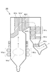
図2を参照して、火炉161について詳しく説明すると、図2において、火炉161は全体として略逆U字状をなしており、図中矢印に沿って燃焼ガスが逆U字状に移動した後、2次節炭器161eを通過後に、再度小さくU字状に反転し、火炉161の出口(図2における矢印の最後)は、脱硝装置181、集塵装置182に接続されている。本実施の形態の微粉炭燃焼施設1においては、火炉161の高さは30mから70mであり、排ガスの流路の全長は300mから1000mに及ぶ。
The
火炉161の下方には、火炉161内のバーナーゾーン161a’付近で微粉炭を燃焼するためのバーナー161aが配置されている。また、火炉161内のU字頂部付近には、火炉上部分割壁161b、最終過熱器161b’、第1の再熱器161f(いずれも熱交換ユニット)が配置されており、さらにそこから横置き1次過熱器161c(熱交換ユニット)が続いて配置されている。さらに、横置き1次過熱器161cと平行して第2の再熱器161f’が設けられており、横置き1次過熱器161cの終端付近からは、1次節炭器161d(熱交換ユニット)、2次節炭器161e(熱交換ユニット)が2段階に設けられている。ここで、節炭器(ECOとも呼ばれる)は、燃焼ガスの保有する熱を利用してボイラ給水を予熱するために設けられた伝熱面群である。なお、本実施の形態においては、火炉161中、1次節炭器161dと2次節炭器161eとは、2段階に分離して設置されているが、このような形態に限定されない。すなわち、火炉161は単一の節炭器のみを有するものであってもよい。
Below the
<A−4:石炭灰処理部18>
石炭灰処理部18は、微粉炭燃焼部16から排出された排ガス中の窒素酸化物を除去する脱硝装置181と、微粉炭燃焼部16から排出された排ガス中の煤塵を除去する集塵装置182と、この集塵装置182により捕集された石炭灰を一時貯蔵する石炭灰回収サイロ183と、を備える。
<A-4: Coal
The coal
脱硝装置181は、排ガス中の窒素酸化物を除去する装置である。すなわち、比較的高温(300〜400℃)の排ガス中に還元剤としてアンモニアガスを注入し、脱硝触媒との作用により排ガス中の窒素酸化物を無害な窒素と水蒸気に分解する、いわゆる乾式アンモニア接触還元法が好適に用いられる。
The
集塵装置182は、排ガス中の石炭灰を電極で収集する装置である。集塵装置182は複数段設けられていることが好ましい。この集塵装置182により捕集された石炭灰のうち、一部は石炭灰分析部20に供給され、残りは石炭灰回収サイロ183に搬送されて一時貯蔵される。また、石炭灰が除去された排ガスは、図示しない脱硫装置を介した後に煙突から排出される。
The
<A−5:石炭灰分析部20>
石炭灰分析部20は、集塵装置182から供給された石炭灰からの有害微量元素の溶出濃度を分析する石炭灰分析装置201を備える。
<A-5: Coal
The
石炭灰分析装置201は、集塵装置182から供給された石炭灰について溶出操作を行って検液を作成し、この検液中の有害微量元素濃度を測定する。そして、石炭灰分析装置201は、この分析結果を溶出抑制剤添加部22に対してフィードバックする。
The
具体的に分析対象となる有害微量元素としては、セレン、フッ素、ホウ素、ヒ素、臭素、シアン、塩素、ヨウ素、硫黄、窒素、リン、シリカ、スズ、チタン、バナジウム、タングステン、ニッケル、マグネシウム、マンガンなどを挙げることができるが、これらに限定されるものではなく、必ずしもこれら全てを分析しなくてもよい。なお、上述のように分析結果を溶出抑制剤添加部22に対してフィードバックする必要があるため、石炭灰分析装置201における分析は、数時間〜1日以内に全て終了することが好ましい。
Specific examples of harmful trace elements to be analyzed include selenium, fluorine, boron, arsenic, bromine, cyan, chlorine, iodine, sulfur, nitrogen, phosphorus, silica, tin, titanium, vanadium, tungsten, nickel, magnesium, manganese However, it is not limited to these, and it is not always necessary to analyze all of them. In addition, since it is necessary to feed back an analysis result with respect to the elution
<A−6:溶出抑制剤添加部22>
溶出抑制剤添加部22は、有害微量元素の溶出抑制剤を添加する溶出抑制剤添加装置221を備える。
<A-6: Elution
The elution
溶出抑制剤添加装置221は、図1に示すように、好ましくは石炭供給部12、微粉炭生成部14と、微粉炭燃焼部16のいずれかに対して有害微量元素の溶出抑制剤を添加する。この溶出抑制剤は、石灰石(CaCO3)、消灰石(Ca(OH)2)、及び生石灰(CaO)からなる群より選択される1種以上を含むものである。この溶出抑制剤は、粒状又は粉末状であることが好ましく、具体的には、平均粒径が10μm〜100μmであることが好ましく、10μm〜70μmであることがより好ましい。
As shown in FIG. 1, the elution
溶出抑制剤添加装置221には、石炭灰分析部20における分析結果がフィードバックされる。溶出抑制剤添加装置221は、この分析結果に応じて、後述するように溶出抑制剤の添加量を決定する。
The analysis result in the coal
<B:本発明の有害微量元素溶出抑制方法>
本発明の有害微量元素溶出抑制方法は、石炭を燃焼させる燃焼ボイラと、前記石炭を前記燃焼ボイラに供給する石炭供給部と、を備えた石炭火力発電システムにおいて、前記石炭の燃焼残渣からの有害微量元素の溶出を抑制する有害微量元素溶出抑制方法であって、前記石炭供給部から前記燃焼ボイラまでの間の系内に、石灰石、消灰石、及び生石灰からなる群より選択される1種以上を含む溶出抑制剤を添加する溶出抑制剤添加ステップと、前記石炭の燃焼残渣を分析し、該燃焼残渣からの有害微量元素の溶出濃度を測定する燃焼残渣分析ステップと、を有し、前記溶出抑制剤添加ステップでは、前記燃焼残渣分析ステップにおける分析結果に応じて、前記溶出抑制剤の添加量を決定するものであるが、これを、上述の微粉炭燃焼施設1を用いて説明する。
<B: Harmful Trace Element Elution Control Method of the Present Invention>
The harmful trace element elution suppression method of the present invention is a coal thermal power generation system comprising a combustion boiler that burns coal and a coal supply unit that supplies the coal to the combustion boiler. A harmful trace element elution suppression method for suppressing trace element elution, wherein the system is selected from the group consisting of limestone, slaked stone, and quicklime in the system from the coal supply section to the combustion boiler. An elution inhibitor adding step for adding an elution inhibitor including the above, and a combustion residue analysis step for analyzing the combustion residue of the coal and measuring the elution concentration of harmful trace elements from the combustion residue, In the elution inhibitor addition step, the addition amount of the elution inhibitor is determined according to the analysis result in the combustion residue analysis step. This is applied to the pulverized
この方法は、石炭を供給する石炭供給工程S10と、供給された石炭を粉砕して微粉炭を生成する微粉炭生成工程S20と、この微粉炭を燃焼する微粉炭燃焼工程S30と、微粉炭の燃焼により生成された石炭灰を処理する石炭灰処理工程S40と、石炭灰からの有害微量元素の溶出濃度を分析する石炭灰分析工程S50と、有害微量元素の溶出抑制剤を供給する溶出抑制剤添加工程S60と、を含み、石炭供給工程S10から石炭灰分析工程S50までの各工程は、それぞれ上述の微粉炭燃焼施設1の石炭供給部12、微粉炭生成部14、微粉炭燃焼部16、石炭灰処理部18、及び石炭灰分析部20において行われる。そして、溶出抑制剤添加工程S60は、好ましくは上述の石炭供給工程S10、微粉炭生成工程S20、微粉炭燃焼工程S30のいずれかで行われる。
This method includes coal supply step S10 for supplying coal, pulverized coal generation step S20 for pulverizing supplied coal to generate pulverized coal, pulverized coal combustion step S30 for burning this pulverized coal, Coal ash treatment step S40 for treating coal ash generated by combustion, coal ash analysis step S50 for analyzing the elution concentration of harmful trace elements from coal ash, and an elution inhibitor supplying an elution inhibitor for harmful trace elements Each step from the coal supply step S10 to the coal ash analysis step S50 includes the
<石炭供給工程S10>
まず、石炭供給工程では、石炭バンカ121に貯蔵された石炭が、給炭機122により、石炭微粉炭機141に供給される。なお、この石炭微粉炭機141に供給される石炭は、具体的には瀝青炭、亜瀝青炭、又は褐炭等であるが、これらの石炭に限定されるものではなく微粉炭燃焼が行える石炭であればよい。
<Coal supply process S10>
First, in the coal supply process, the coal stored in the
<微粉炭生成工程S20>
次に、微粉炭生成工程では、給炭機122から供給された石炭が石炭微粉炭機141により粉砕され、これにより、微粉炭が生成される。生成された微粉炭は、火炉161に供給される。このとき、この微粉炭生成工程で粉状に形成された微粉炭の平均の粒度は、微粉炭燃焼で一般的に用いられる粒径範囲であればよく、一般的には、74μmアンダー80wt%以上の粉砕度である。なお、この範囲は溶出抑制剤が添加された場合にも適用できる。
<Pulverized coal production process S20>
Next, in the pulverized coal production step, the coal supplied from the
<微粉炭燃焼工程S30>
次に、微粉炭燃焼工程では、石炭微粉炭機141で生成された微粉炭が、火炉161により燃焼される。図2に示すように、バーナーゾーン161a’においては微粉炭が燃焼されるが、このときの温度は1300℃から1500℃に達し、燃焼によって生成される石炭灰は、矢印の方向に沿って上昇して排ガスと共に火炉上部分割壁161b(熱交換ユニット)、横置き1次過熱器161c(熱交換ユニット)を通過し、1次節炭器161d(熱交換ユニット)、2次節炭器161e(熱交換ユニット)を順次通過する。
<Pulverized coal combustion process S30>
Next, in the pulverized coal combustion process, the pulverized coal generated by the coal pulverized
この火炉上部分割壁、過熱器、再熱器付近は850℃から900℃前後が、節炭器付近は450℃から500℃前後が維持されている領域であり、この燃焼ガスの保有する熱を利用してボイラ給水を予熱するために設けられた伝熱面群を通過することによって熱交換され、温度が低下する。排ガスがバーナーゾーン161a’から過熱器付近まで到達するまでに要する時間は、おおむね5秒から15秒である。そして、その後、後段の脱硝装置181、集塵装置182に送られる。この微粉炭燃焼工程で生成される石炭灰は、通常、その平均の粒度が1μmから100μmの範囲内の粉末状である。
The vicinity of the furnace upper dividing wall, superheater, and reheater is the region where 850 to 900 ° C is maintained, and the vicinity of the economizer is the region where 450 ° C to 500 ° C is maintained. Heat is exchanged by passing through a heat transfer surface group provided to preheat boiler feedwater by using it, and the temperature decreases. The time required for the exhaust gas to reach the vicinity of the superheater from the
<石炭灰処理工程S40>
次に、石炭灰処理工程では、微粉炭の燃焼によって発生した排ガスが脱硝装置181に送られて脱硝され、さらに、集塵装置182によって排ガス中の石炭灰が集塵される。この集塵装置182により捕集された石炭灰のうち、一部は石炭灰分析部20に供給され、残りは石炭灰回収サイロ183に搬送される。また、石炭灰が除去された排ガスは、図示しない脱硫装置を介した後に煙突から排出される。
<Coal ash treatment process S40>
Next, in the coal ash treatment process, the exhaust gas generated by the combustion of pulverized coal is sent to the
<石炭灰分析工程S50>
次に、石炭灰分析工程では、集塵装置182から供給された石炭灰からのホウ素、フッ素、セレン、ヒ素などの有害微量元素の溶出濃度が分析され、分析結果が溶出抑制剤添加部22に対してフィードバックされる。
<Coal ash analysis process S50>
Next, in the coal ash analysis step, the elution concentration of harmful trace elements such as boron, fluorine, selenium, and arsenic from the coal ash supplied from the
この分析方法としては、例えばJIS K0102に準拠した公定法を用いることができる。例えば、セレンについては水素化合物発生原子吸光法、フッ素についてはランタンアリザリンコンプレキソン吸光光度法やイオンクロマトグラフ法、ホウ素についてはメチレンブルー吸光光度法やICP質量分析法、ヒ素については水素化合物発生原子吸光法や水素化合物発生ICP法などを用いることができる。但し、セレンの場合、JIS K0102に準拠した水素化合物発生ICP法では、分析に7日程度要し、分析結果を迅速にフィードバックすることができなくなるため、水素化合物発生ICP法以外の方法で分析することが好ましい。 As this analysis method, for example, an official method based on JIS K0102 can be used. For example, hydride generation atomic absorption for selenium, lanthanum alizarin complexone absorptiometry and ion chromatography for fluorine, methylene blue absorptiometry and ICP mass spectrometry for boron, and hydride generation atomic absorption for arsenic Or a hydrogen compound generation ICP method can be used. However, in the case of selenium, the hydride generation ICP method according to JIS K0102 requires about 7 days for analysis, and the analysis results cannot be fed back quickly. Therefore, the analysis is performed by a method other than the hydride generation ICP method. It is preferable.
なお、この石炭灰分析工程における分析方法は、公定法に限定されるものではなく、公定法と同程度の精度で分析できるものであれば、簡易法であっても構わない。例えば、セレンの分析方法としては、本件出願人が先に提案した特開2005−291968号公報に記載された方法を用いることができる。この方法によれば、JIS K0102に準拠した水素化合物発生原子吸光法と同程度の精度で、且つ水素化合物発生原子吸光法で例えば4時間要していた分析を、2時間程度と迅速に行うことができる。 The analysis method in the coal ash analysis step is not limited to the official method, and may be a simple method as long as it can be analyzed with the same degree of accuracy as the official method. For example, as a method for analyzing selenium, the method described in Japanese Patent Application Laid-Open No. 2005-291968 previously proposed by the present applicant can be used. According to this method, it is possible to perform analysis as fast as about 2 hours, for example, with the same degree of accuracy as the hydrogen compound generation atomic absorption method according to JIS K0102, and with the hydrogen compound generation atomic absorption method taking, for example, 4 hours. Can do.
<溶出抑制剤添加工程S60>
溶出抑制剤添加工程S60は、図1に示すように、好ましくは上述の石炭供給工程S10、微粉炭生成工程S20、微粉炭燃焼工程S30のいずれかに対して行われる。
<Elution inhibitor addition step S60>
As shown in FIG. 1, the elution inhibitor addition step S60 is preferably performed for any of the above-described coal supply step S10, pulverized coal generation step S20, or pulverized coal combustion step S30.
なお、溶出抑制剤の添加場所は、石炭供給工程S10から微粉炭燃焼工程S30までの間の系内であれば特に限定されず、例えば、石炭供給工程S10と微粉炭生成工程S20との間の移送路や、微粉炭生成工程S20と微粉炭燃焼工程S30との間の移送路などで行われてもよい。 In addition, the addition place of an elution inhibitor will not be specifically limited if it is in the system from coal supply process S10 to pulverized coal combustion process S30, for example, between coal supply process S10 and pulverized coal production process S20 It may be performed in a transfer path or a transfer path between the pulverized coal generation step S20 and the pulverized coal combustion step S30.
具体的には、例えば、給炭機122から石炭微粉炭機141に輸送する際の移送中のベルトコンベア上に溶出抑制剤を供給して混合する方法、溶出抑制剤を石炭微粉炭機141の石炭ホッパ(図示せず)に直接投入する方法、石炭微粉炭機141と火炉161との間の配管に剤投入口を設けて供給する方法、火炉161(バーナーゾーン161a’)へ燃焼用空気と共に直接投入する方法、火炉161の一部を構成する、火炉上部分割壁161b、最終過熱器161b’、第1の再熱器161f、横置き1次過熱器161c、第2の再熱器161f’、1次節炭器161d、2次節炭器161eなどの熱交換ユニット付近に添加する方法、などが挙げられるがこれらに限定されるものではない。このように、本発明の方法は新たな設備を必要とせず、既存の設備の軽微な改良で適用可能であるため、既存設備を有効利用することができ、コスト的にも有利である。
Specifically, for example, a method of supplying and mixing an elution inhibitor onto a belt conveyor that is being transferred when transporting from the
この溶出抑制剤添加工程S60では、石炭灰分析工程S50における分析結果に応じて、溶出抑制剤の添加量を決定する。具体的には、石炭灰分析工程S50における分析の結果、石炭灰からの有害微量元素の溶出濃度が所定の範囲を上回る場合には、上回った割合に応じて溶出抑制剤の添加量を増加させ、石炭灰からの有害微量元素の溶出濃度がこの所定の範囲を下回る場合には、下回った割合に応じて溶出抑制剤の添加量を減少させる。これにより、石炭灰からの有害微量元素の溶出濃度を平均して所定の範囲内に保つことができる。この所定範囲の上限値は、例えば法律で規定されている溶出濃度の規制値とすることができ、下限値は、溶出抑制効果が頭打ちとなったときの溶出濃度よりも若干大きな値とすることができる。例えばセレンの場合、上限値は溶出濃度の規制値である0.01mg/Lとすることができ、下限値は0.001mg/Lとすることができる。 In this elution inhibitor addition step S60, the addition amount of the elution inhibitor is determined according to the analysis result in the coal ash analysis step S50. Specifically, as a result of the analysis in the coal ash analysis step S50, when the elution concentration of harmful trace elements from the coal ash exceeds a predetermined range, the addition amount of the elution inhibitor is increased in accordance with the ratio exceeded. When the elution concentration of harmful trace elements from coal ash is less than this predetermined range, the amount of the elution inhibitor added is reduced according to the ratio below. Thereby, the elution concentration of harmful trace elements from coal ash can be averaged and kept within a predetermined range. The upper limit value of the predetermined range can be, for example, a regulation value of the elution concentration stipulated by law, and the lower limit value should be a value slightly larger than the elution concentration when the elution suppression effect has reached its peak. Can do. For example, in the case of selenium, the upper limit value can be 0.01 mg / L, which is the regulation value of the elution concentration, and the lower limit value can be 0.001 mg / L.
なお、石炭灰分析工程S50において複数の有害微量元素について分析を行っている場合、上限値を上回る元素が存在するときには、その中で上限値を上回った割合が最も大きい元素に基づいて溶出抑制剤の添加量を決定し、上限値を上回る元素が存在しないときには、下限値を上回った割合が最も大きい元素に基づいて溶出抑制剤の添加量を決定することが好ましい。 In addition, when analyzing about some harmful trace elements in coal ash analysis process S50, when there exists an element exceeding an upper limit, an elution inhibitor based on the element with the largest ratio exceeding the upper limit among them. When there is no element exceeding the upper limit value, it is preferable to determine the addition amount of the elution inhibitor based on the element having the largest ratio exceeding the lower limit value.
このように、溶出抑制剤添加工程S60では、石炭灰分析工程S50における分析結果がフィードバックされる周期で溶出抑制剤の添加量が増減するが、この添加量は、石炭100重量部に対して0.3重量部以上10重量部以下の範囲であることが好ましい。これは、溶出抑制剤の添加量が石炭100重量部に対して0.3重量部未満であると、有害微量元素の溶出抑制効果が不十分となり、10重量部を超えても、有害微量元素の溶出抑制効果に大きな向上が認められず、また、石炭灰表面の融点降下によって火炉内壁への石炭灰の多量の付着(スラッギング)を起こす恐れがあるためである。 As described above, in the elution inhibitor addition step S60, the addition amount of the elution inhibitor increases or decreases in a cycle in which the analysis result in the coal ash analysis step S50 is fed back, but this addition amount is 0 with respect to 100 parts by weight of coal. It is preferably in the range of 3 to 10 parts by weight. This is because if the addition amount of the elution inhibitor is less than 0.3 parts by weight with respect to 100 parts by weight of coal, the elution suppression effect of harmful trace elements becomes insufficient, and even if it exceeds 10 parts by weight, harmful trace elements This is because no significant improvement is observed in the elution suppression effect of coal, and a large amount of coal ash (slagging) may adhere to the inner wall of the furnace due to a melting point drop on the surface of the coal ash.
上述したように、溶出抑制剤は、石灰石(CaCO3)、消灰石(Ca(OH)2)、及び生石灰(CaO)からなる群より選択される1種以上を含むものである。この溶出抑制剤の添加により、石炭灰中に含まれる有害微量元素の溶出を、元素の種類に関わりなく抑制できる。具体的に溶出を防止することができる有害微量元素としては、特に限定されないが、セレン、フッ素、ホウ素、ヒ素、臭素、シアン、塩素、ヨウ素、硫黄、窒素、リン、シリカ、スズ、チタン、バナジウム、タングステン、ニッケル、マグネシウム、マンガンなどを挙げることができる。 As described above, the elution inhibitor includes one or more selected from the group consisting of limestone (CaCO 3 ), slaked stone (Ca (OH) 2 ), and quicklime (CaO). By adding this elution inhibitor, the elution of harmful trace elements contained in coal ash can be suppressed regardless of the type of element. Specific examples of harmful trace elements that can prevent elution include, but are not limited to, selenium, fluorine, boron, arsenic, bromine, cyan, chlorine, iodine, sulfur, nitrogen, phosphorus, silica, tin, titanium, vanadium. , Tungsten, nickel, magnesium, manganese and the like.
溶出抑制剤の添加により石炭灰からの有害微量元素の溶出が抑制されるメカニズムは以下の通りである。 The mechanism by which the elution of harmful trace elements from coal ash is suppressed by the addition of an elution inhibitor is as follows.
石炭供給部12から微粉炭燃焼部16までの間の系内に溶出抑制剤を添加することによって、石炭灰中に含まれている酸化カルシウム量が増加する。ここで、酸化カルシウムは、石炭灰中に含有された有害微量元素の化合物、例えば、酸化セレン、三酸化二ヒ素、及び酸化ホウ素などと反応して、それぞれ亜セレン酸カルシウム、ヒ酸カルシウム、ホウ酸カルシウムなどの難溶性又は不溶性の化合物(以下、「難溶性不溶性化合物」という)を生成する。すなわち、有害微量元素は酸化カルシウムによって化学的に捕捉され難溶性不溶性化合物を生成する。
By adding an elution inhibitor into the system between the
したがって、石炭供給部12から微粉炭燃焼部16までの間の系内に溶出抑制剤を添加することにより、系内の石炭灰中の酸化カルシウム量が増えたことによって、有害微量元素は酸化カルシウムに化学的に捕捉され難溶性不溶性化合物となっている可能性が高く、石炭灰からの溶出が抑制される。
Therefore, by adding an elution inhibitor into the system between the
また、溶出抑制剤を、燃焼中又は燃焼前の石炭の段階で添加した場合、石炭灰の溶融温度が低下する。この結果、火炉161内の1300℃から1500℃という高温の条件においては、シリカ、アルミナを主成分とする石炭灰の表面が軟化(溶融)し、粘性をもった石炭灰粒子が、有害微量元素と接触して石炭灰の内部に取り込まれる。すなわち、有害微量元素の化合物は石炭灰内に物理的に捕捉され、石炭灰からの溶出が抑制される。
Moreover, when an elution inhibitor is added at the stage of coal during combustion or before combustion, the melting temperature of coal ash decreases. As a result, under the high temperature conditions of 1300 ° C. to 1500 ° C. in the
以上のように、溶出抑制剤を石炭供給部12から微粉炭燃焼部16までの間の系内に添加することにより、石炭灰からの有害微量元素の溶出を効果的に抑制することができる。
As described above, by adding an elution inhibitor into the system between the
以下、本発明を実施例によってさらに具体的に説明する。
<試験例1:小規模試験>
<実施例1>
中国産の瀝青炭(以下、石炭A)100重量部に、石灰石を3重量部混合した。この混合物をインペラーミルにより粉砕し、74μmアンダー80wt%、40μmアンダー50wt%、20μmアンダー25wt%となる粉体を得た。この粉体(石灰石含有微粉炭)を、微粉炭燃焼炉に供給し燃焼させた。微粉炭燃焼炉には、内径30cm、炉長2.5mの自燃式の縦型炉を使用し、粉体の投入量は、5〜6kg/hとした。このときの炉内温度は、1300℃に達した。燃焼後、排出された石炭灰を、燃焼炉後段のバグフィルターにて採取した。
Hereinafter, the present invention will be described more specifically with reference to examples.
<Test Example 1: Small scale test>
<Example 1>
3 parts by weight of limestone was mixed with 100 parts by weight of Chinese bituminous coal (hereinafter referred to as coal A). This mixture was pulverized by an impeller mill to obtain a powder having 74 μm under 80 wt%, 40 μm under 50 wt%, and 20 μm under 25 wt%. This powder (limestone-containing pulverized coal) was supplied to a pulverized coal combustion furnace and burned. As the pulverized coal combustion furnace, a self-burning vertical furnace having an inner diameter of 30 cm and a furnace length of 2.5 m was used, and the amount of powder charged was 5 to 6 kg / h. The furnace temperature at this time reached 1300 ° C. After combustion, the discharged coal ash was collected with a bag filter at the rear stage of the combustion furnace.
採取した石炭灰について、環境庁告示46号による溶出操作を行って検液を作成し、この検液中のセレン、フッ素、ホウ素、ヒ素の各有害微量元素の濃度を測定した。測定結果を表1に示す。溶出濃度の単位はいずれも[mg/L]である。なお、セレン及びヒ素は水素化合物発生原子吸光法で、フッ素はイオンクロマトグラフ法で、ホウ素はICP質量分析法でそれぞれ測定した。 The collected coal ash was subjected to an elution operation according to Environment Agency Notification No. 46 to prepare a test solution, and the concentrations of toxic elements of selenium, fluorine, boron and arsenic in the test solution were measured. The measurement results are shown in Table 1. The unit of elution concentration is [mg / L] in all cases. Selenium and arsenic were measured by hydrogen compound generation atomic absorption, fluorine was measured by ion chromatography, and boron was measured by ICP mass spectrometry.

<比較例1>
実施例1において、石炭Aに石灰石を添加しなかった他は、実施例1と同様にして石炭灰を採取し、評価した。測定結果を表1に示す。
<Comparative Example 1>
In Example 1, coal ash was collected and evaluated in the same manner as in Example 1 except that limestone was not added to Coal A. The measurement results are shown in Table 1.
<実施例2>
実施例1において、石炭Aに代えてオーストラリア産の瀝青炭(石炭B)を使用した他は、実施例1と同様にして石炭灰を採取し、評価した。測定結果を表1に示す。
<Example 2>
In Example 1, coal ash was collected and evaluated in the same manner as in Example 1 except that Australian bituminous coal (coal B) was used instead of coal A. The measurement results are shown in Table 1.
<比較例2>
実施例2において、石炭Bに石灰石を添加しなかった他は、実施例2と同様にして石炭灰を採取し、評価した。測定結果を表1に示す。
<Comparative example 2>
In Example 2, coal ash was collected and evaluated in the same manner as in Example 2 except that limestone was not added to Coal B. The measurement results are shown in Table 1.
表1に示した測定結果から明らかなように、本発明の方法を実施した場合は、石炭灰からの各有害微量元素の溶出を抑制できる。したがって、ミルに投入する前に、石炭に石灰石等の添加剤を投入するという簡単な操作によって、石炭灰に含まれている有害微量元素の溶出を抑制できることが確認できた。 As is clear from the measurement results shown in Table 1, when the method of the present invention is carried out, elution of each harmful trace element from coal ash can be suppressed. Therefore, it was confirmed that elution of harmful trace elements contained in coal ash can be suppressed by a simple operation of adding an additive such as limestone to coal before putting it into the mill.
<試験例2:実機試験>
<実施例3>
図1、図2に示すような装置を用い、図1における石炭供給部12の位置で溶出抑制剤(石灰石)を添加した。なお、石灰石は石炭灰中のCa含有率(質量%)が表2の割合となるようにした。また、その後、石炭灰回収サイロ183で回収された石炭灰について、有害微量元素(セレン、ホウ素、及びヒ素)の溶出濃度を、その減少率と共に表2に示す。ここでは、石炭として豪州炭を用いた。また、表2におけるそれぞれの溶出量の数値は、添加後溶出量/未添加溶出量である。ここで、添加後溶出量は本発明の実施例に相当し、未添加溶出量は、本発明の溶出抑制剤を添加していない系であり、比較例に相当するものである。なお、溶出濃度の単位はいずれも[mg/L]であり、減少率の単位は[%]である。
<Test Example 2: Actual machine test>
<Example 3>
Using an apparatus as shown in FIGS. 1 and 2, an elution inhibitor (limestone) was added at the position of the
なお、以下に示す溶出濃度の測定結果は、試験例1と同じく環境庁告示46号による溶出操作を行って検液を作成し、この検液中の各有害微量元素の濃度を測定したものである。また、各有害微量元素のうち、セレン及びヒ素は水素化物発生原子吸光法で、フッ素はイオンクロマトグラフ法で、ホウ素はICP質量分析法でそれぞれ測定した。 The measurement results of the elution concentration shown below are the same as those in Test Example 1 except that the test solution was prepared by the elution operation according to Environment Agency Notification No. 46 and the concentration of each harmful trace element in this test solution was measured. is there. Of the harmful trace elements, selenium and arsenic were measured by hydride generation atomic absorption, fluorine was measured by ion chromatography, and boron was measured by ICP mass spectrometry.
また、表2のサンプリング箇所である、ECOは、図2における1次節炭器161dである。また、EP(集塵装置)一段目からEP(集塵装置)四段目は、直列4段で構成される集塵装置182のそれぞれの集塵装置である。
Moreover, ECO which is a sampling location of Table 2 is the
表2の結果によれば、セレン、ホウ素、ヒ素において溶出抑制効果が認められていることが分かる。なお、カッコ内の低減率は参考値であり、この数値が規制値をオーバーしていても、上述のように溶出抑制剤の添加量が増減される結果、平均として規制値以下となるため問題ない。 According to the results in Table 2, it can be seen that an elution suppression effect is recognized in selenium, boron and arsenic. Note that the reduction rate in parentheses is a reference value, and even if this value exceeds the regulation value, the amount of the dissolution inhibitor added or decreased as described above results in an average that is less than the regulation value. Absent.
以上、本発明を実施する最良の形態について説明したが、本発明は上述した実施の形態に限定されるものではなく、本発明の要旨を変更しない範囲で種々の変更が可能である。 Although the best mode for carrying out the present invention has been described above, the present invention is not limited to the above-described embodiment, and various modifications can be made without departing from the scope of the present invention.
例えば、上述した実施の形態では、石炭灰分析部20における分析対象が集塵装置182で集塵される石炭灰、すなわちフライアッシュであるものとして説明したが、これに限定されるものではなく、火炉161から落下するクリンカアッシュや、1次節炭器161d、2次節炭器161e、空気予熱器162、及び脱硝装置181で捕集されるシンダアッシュを分析対象としても構わない。但し、フライアッシュの量が最も多く、且つ有害微量元素の溶出も多いため、フライアッシュを分析対象とすることが好ましい。
For example, in the above-described embodiment, the analysis target in the coal
1 微粉炭燃焼施設
12 石炭供給部
121 石炭バンカ
122 給炭機
14 微粉炭生成部
141 石炭微粉炭機
142 通風機
16 微粉炭燃焼部
161 火炉
162 空気予熱器
163 通風機
18 石炭灰処理部
181 脱硝装置
182 集塵装置
183 石炭灰回収サイロ
20 石炭灰分析部
201 石炭灰分析装置
22 溶出抑制剤添加部
221 溶出抑制剤添加装置
S10 石炭供給工程
S20 微粉炭生成工程
S30 微粉炭燃焼工程
S40 石炭灰処理工程
S50 石炭灰分析工程
S60 溶出抑制剤添加工程
DESCRIPTION OF
Claims (8)
前記石炭供給部から前記熱交換ユニットまでの間の系内に、石灰石、消灰石、及び生石灰からなる群より選択される1種以上を含む溶出抑制剤を添加する溶出抑制剤添加ステップと、
前記石炭の燃焼残渣を分析し、該燃焼残渣からの有害微量元素の溶出濃度を測定する燃焼残渣分析ステップと、を有し、
前記溶出抑制剤添加ステップでは、前記燃焼残渣分析ステップにおける分析の結果、前記石炭の燃焼残渣からの有害微量元素の溶出濃度が所定の範囲を上回る場合には前記溶出抑制剤の添加量を増加させ、前記石炭の燃焼残渣からの有害微量元素の溶出濃度が前記所定の範囲を下回る場合には前記溶出抑制剤の添加量を減少させることを特徴とする有害微量元素溶出抑制方法。 A combustion boiler having a heat exchanger unit that preheats boiler feedwater using a burner zone that burns coal, and a heat that is provided downstream of the burner zone and that is stored in the burner zone and that is generated in the burner zone; In a coal thermal power generation system comprising a coal supply unit that supplies to the burner zone, a harmful trace element elution suppression method that suppresses elution of harmful trace elements from the combustion residue of the coal,
In the system between the coal supply unit and the heat exchange unit, an elution inhibitor adding step for adding an elution inhibitor containing at least one selected from the group consisting of limestone, slaked stone, and quicklime;
A combustion residue analysis step of analyzing the combustion residue of the coal and measuring an elution concentration of harmful trace elements from the combustion residue;
In the elution inhibitor addition step, when the elution concentration of harmful trace elements from the combustion residue of coal exceeds a predetermined range as a result of the analysis in the combustion residue analysis step, the addition amount of the elution inhibitor is increased. A method for inhibiting the elution of harmful trace elements, wherein the amount of the elution inhibitor added is decreased when the elution concentration of harmful trace elements from the combustion residue of coal is below the predetermined range .
前記石炭供給部から前記熱交換ユニットまでの間の系内に、石灰石、消灰石、及び生石灰からなる群より選択される1種以上を含む溶出抑制剤を添加する溶出抑制剤添加ステップと、
前記石炭の燃焼残渣を分析し、該燃焼残渣からの有害微量元素の溶出濃度を測定する燃焼残渣分析ステップと、を有し、
前記溶出抑制剤添加ステップでは、前記燃焼残渣分析ステップにおける分析結果に応じて、前記溶出抑制剤の添加量を決定し、前記溶出抑制剤を、前記熱交換ユニット付近で添加する、ことを特徴とする有害微量元素溶出抑制方法。 A combustion boiler having a heat exchanger unit that preheats boiler feedwater using a burner zone that burns coal, and a heat that is provided downstream of the burner zone and that is stored in the burner zone and that is generated in the burner zone; In a coal thermal power generation system comprising a coal supply unit that supplies to the burner zone, a harmful trace element elution suppression method that suppresses elution of harmful trace elements from the combustion residue of the coal,
In the system between the coal supply unit and the heat exchange unit, an elution inhibitor adding step for adding an elution inhibitor containing at least one selected from the group consisting of limestone, slaked stone, and quicklime;
A combustion residue analysis step of analyzing the combustion residue of the coal and measuring an elution concentration of harmful trace elements from the combustion residue;
In the elution inhibitor addition step, the addition amount of the elution inhibitor is determined according to the analysis result in the combustion residue analysis step, and the elution inhibitor is added in the vicinity of the heat exchange unit. To prevent harmful trace element elution.
前記石炭の燃焼残渣からの有害微量元素の溶出を抑制するため、前記石炭供給部から前記熱交換ユニットまでの間の系内に、石灰石、消灰石、及び生石灰からなる群より選択される1種以上を含む溶出抑制剤を添加する溶出抑制剤添加部と、
前記石炭の燃焼残渣を分析し、該燃焼残渣からの有害微量元素の溶出濃度を測定する燃焼残渣分析部と、を備え、
前記溶出抑制剤添加部は、前記燃焼残渣分析部による分析の結果、前記石炭の燃焼残渣からの有害微量元素の溶出濃度が所定の範囲を上回る場合には前記溶出抑制剤の添加量を増加させ、前記石炭の燃焼残渣からの有害微量元素の溶出濃度が前記所定の範囲を下回る場合には前記溶出抑制剤の添加量を減少させる、
ことを特徴とする石炭火力発電システム。 A combustion boiler having a heat exchanger unit that preheats boiler feedwater using a burner zone that burns coal, and a heat that is provided downstream of the burner zone and that is stored in the burner zone and that is generated in the burner zone; In a coal-fired power generation system comprising a coal supply unit for supplying to the burner zone,
In order to suppress the elution of harmful trace elements from the combustion residue of the coal, 1 selected from the group consisting of limestone, slaked stone, and quicklime in the system from the coal supply unit to the heat exchange unit An elution inhibitor addition part for adding an elution inhibitor containing seeds or more,
A combustion residue analysis unit for analyzing the combustion residue of the coal and measuring an elution concentration of harmful trace elements from the combustion residue;
The elution inhibitor addition unit increases the amount of the elution inhibitor added when the elution concentration of harmful trace elements from the combustion residue of coal exceeds a predetermined range as a result of analysis by the combustion residue analysis unit. , If the elution concentration of harmful trace elements from the combustion residue of the coal is below the predetermined range, to reduce the amount of the elution inhibitor added,
Coal-fired power generation system characterized by that.
Priority Applications (1)
| Application Number | Priority Date | Filing Date | Title |
|---|---|---|---|
| JP2007005142A JP4726811B2 (en) | 2007-01-12 | 2007-01-12 | Harmful trace element elution suppression method and coal thermal power generation system |
Applications Claiming Priority (1)
| Application Number | Priority Date | Filing Date | Title |
|---|---|---|---|
| JP2007005142A JP4726811B2 (en) | 2007-01-12 | 2007-01-12 | Harmful trace element elution suppression method and coal thermal power generation system |
Publications (2)
| Publication Number | Publication Date |
|---|---|
| JP2008170106A JP2008170106A (en) | 2008-07-24 |
| JP4726811B2 true JP4726811B2 (en) | 2011-07-20 |
Family
ID=39698368
Family Applications (1)
| Application Number | Title | Priority Date | Filing Date |
|---|---|---|---|
| JP2007005142A Active JP4726811B2 (en) | 2007-01-12 | 2007-01-12 | Harmful trace element elution suppression method and coal thermal power generation system |
Country Status (1)
| Country | Link |
|---|---|
| JP (1) | JP4726811B2 (en) |
Families Citing this family (1)
| Publication number | Priority date | Publication date | Assignee | Title |
|---|---|---|---|---|
| ITBA20130084A1 (en) * | 2013-12-27 | 2015-06-28 | Itea Spa | PRESSURIZED OXYCOMBUSTION PROCESS |
Citations (3)
| Publication number | Priority date | Publication date | Assignee | Title |
|---|---|---|---|---|
| JPS6262123A (en) * | 1985-09-13 | 1987-03-18 | Babcock Hitachi Kk | Method for controlling temperatures of primary air at outlet of coal pulverizer for boiler |
| JPH08178240A (en) * | 1994-09-26 | 1996-07-12 | Foster Wheeler Energy Corp | Reducing method for gas discharge of halogen compound of fluidized-bed reactor |
| JPH0972532A (en) * | 1995-09-07 | 1997-03-18 | Hokkaido Electric Power Co Inc:The | Method for reducing hydrogen fluoride in exhaust gas |
-
2007
- 2007-01-12 JP JP2007005142A patent/JP4726811B2/en active Active
Patent Citations (3)
| Publication number | Priority date | Publication date | Assignee | Title |
|---|---|---|---|---|
| JPS6262123A (en) * | 1985-09-13 | 1987-03-18 | Babcock Hitachi Kk | Method for controlling temperatures of primary air at outlet of coal pulverizer for boiler |
| JPH08178240A (en) * | 1994-09-26 | 1996-07-12 | Foster Wheeler Energy Corp | Reducing method for gas discharge of halogen compound of fluidized-bed reactor |
| JPH0972532A (en) * | 1995-09-07 | 1997-03-18 | Hokkaido Electric Power Co Inc:The | Method for reducing hydrogen fluoride in exhaust gas |
Also Published As
| Publication number | Publication date |
|---|---|
| JP2008170106A (en) | 2008-07-24 |
Similar Documents
| Publication | Publication Date | Title |
|---|---|---|
| JP5121564B2 (en) | Hazardous trace element elution inhibitor and method of inhibiting harmful trace element elution | |
| JP4942559B2 (en) | Exhaust gas purifier and method for capturing harmful trace elements | |
| JP5456226B2 (en) | Methods for controlling the elution of harmful trace elements | |
| JP4726811B2 (en) | Harmful trace element elution suppression method and coal thermal power generation system | |
| JP4744370B2 (en) | Method for improving dust collection efficiency of dust collector | |
| JP4671976B2 (en) | Hazardous trace element elution inhibitor addition amount calculation method and harmful trace element elution suppression method using the same | |
| JP4644635B2 (en) | Clinker ash production promotion method and clinker ash production promoter | |
| JP5177965B2 (en) | A method for capturing harmful trace elements in exhaust gas. | |
| JP5063477B2 (en) | Hazardous trace element elution inhibitor and method of inhibiting harmful trace element elution | |
| JP4726812B2 (en) | Methods for controlling the elution of harmful trace elements | |
| JP4901268B2 (en) | Method for suppressing elution of harmful trace elements and elution inhibitor for coal addition used therefor | |
| JP4726813B2 (en) | Methods for controlling the elution of harmful trace elements | |
| JP4644636B2 (en) | Clinker ash production promotion method and clinker ash production promoter | |
| JP2008170107A (en) | Oxide reducing method and oxide reducer for coal addition used in the same | |
| JP5036324B2 (en) | Methods for controlling the elution of harmful trace elements | |
| JP5153144B2 (en) | Methods for controlling the elution of harmful trace elements | |
| JP4726810B2 (en) | Method for suppressing elution of harmful trace elements or their compounds using organic waste | |
| JP5073216B2 (en) | Method for suppressing elution of harmful trace elements and elution inhibitor for coal addition used therefor | |
| JP5420142B2 (en) | Method for improving dust collection efficiency of dust collector | |
| JP2008275181A (en) | Method of inhibiting elution of harmful trace element | |
| JP2009276000A (en) | Noxious trace element elution inhibitor and noxious trace element elution suppression method | |
| JP2008169338A (en) | Method of reducing unburned coal | |
| JP6079940B2 (en) | Arsenic elution suppression method | |
| JP5036467B2 (en) | Coal-fired power generation system and hexavalent chromium elution reduction method | |
| WO2016067650A1 (en) | Fluorine-elution suppression method |
Legal Events
| Date | Code | Title | Description |
|---|---|---|---|
| A621 | Written request for application examination |
Free format text: JAPANESE INTERMEDIATE CODE: A621 Effective date: 20090804 |
|
| A977 | Report on retrieval |
Free format text: JAPANESE INTERMEDIATE CODE: A971007 Effective date: 20100604 |
|
| A131 | Notification of reasons for refusal |
Free format text: JAPANESE INTERMEDIATE CODE: A131 Effective date: 20100622 |
|
| A521 | Request for written amendment filed |
Free format text: JAPANESE INTERMEDIATE CODE: A523 Effective date: 20100820 |
|
| A131 | Notification of reasons for refusal |
Free format text: JAPANESE INTERMEDIATE CODE: A131 Effective date: 20110111 |
|
| A521 | Request for written amendment filed |
Free format text: JAPANESE INTERMEDIATE CODE: A523 Effective date: 20110309 |
|
| TRDD | Decision of grant or rejection written | ||
| A01 | Written decision to grant a patent or to grant a registration (utility model) |
Free format text: JAPANESE INTERMEDIATE CODE: A01 Effective date: 20110405 |
|
| A01 | Written decision to grant a patent or to grant a registration (utility model) |
Free format text: JAPANESE INTERMEDIATE CODE: A01 |
|
| A61 | First payment of annual fees (during grant procedure) |
Free format text: JAPANESE INTERMEDIATE CODE: A61 Effective date: 20110412 |
|
| R150 | Certificate of patent or registration of utility model |
Ref document number: 4726811 Country of ref document: JP Free format text: JAPANESE INTERMEDIATE CODE: R150 Free format text: JAPANESE INTERMEDIATE CODE: R150 |
|
| FPAY | Renewal fee payment (event date is renewal date of database) |
Free format text: PAYMENT UNTIL: 20140422 Year of fee payment: 3 |
|
| FPAY | Renewal fee payment (event date is renewal date of database) |
Free format text: PAYMENT UNTIL: 20140422 Year of fee payment: 3 |
|
| R250 | Receipt of annual fees |
Free format text: JAPANESE INTERMEDIATE CODE: R250 |
|
| R250 | Receipt of annual fees |
Free format text: JAPANESE INTERMEDIATE CODE: R250 |
|
| R250 | Receipt of annual fees |
Free format text: JAPANESE INTERMEDIATE CODE: R250 |
|
| R250 | Receipt of annual fees |
Free format text: JAPANESE INTERMEDIATE CODE: R250 |
|
| R250 | Receipt of annual fees |
Free format text: JAPANESE INTERMEDIATE CODE: R250 |
|
| R250 | Receipt of annual fees |
Free format text: JAPANESE INTERMEDIATE CODE: R250 |
|
| R250 | Receipt of annual fees |
Free format text: JAPANESE INTERMEDIATE CODE: R250 |
|
| R250 | Receipt of annual fees |
Free format text: JAPANESE INTERMEDIATE CODE: R250 |
|
| R250 | Receipt of annual fees |
Free format text: JAPANESE INTERMEDIATE CODE: R250 |