JP4718920B2 - Coordinate detection device - Google Patents
Coordinate detection device Download PDFInfo
- Publication number
- JP4718920B2 JP4718920B2 JP2005204778A JP2005204778A JP4718920B2 JP 4718920 B2 JP4718920 B2 JP 4718920B2 JP 2005204778 A JP2005204778 A JP 2005204778A JP 2005204778 A JP2005204778 A JP 2005204778A JP 4718920 B2 JP4718920 B2 JP 4718920B2
- Authority
- JP
- Japan
- Prior art keywords
- common electrode
- film
- potential
- resistive
- coordinate detection
- Prior art date
- Legal status (The legal status is an assumption and is not a legal conclusion. Google has not performed a legal analysis and makes no representation as to the accuracy of the status listed.)
- Expired - Fee Related
Links
Images


Classifications
-
- G—PHYSICS
- G06—COMPUTING; CALCULATING OR COUNTING
- G06F—ELECTRIC DIGITAL DATA PROCESSING
- G06F3/00—Input arrangements for transferring data to be processed into a form capable of being handled by the computer; Output arrangements for transferring data from processing unit to output unit, e.g. interface arrangements
- G06F3/01—Input arrangements or combined input and output arrangements for interaction between user and computer
- G06F3/03—Arrangements for converting the position or the displacement of a member into a coded form
- G06F3/041—Digitisers, e.g. for touch screens or touch pads, characterised by the transducing means
- G06F3/045—Digitisers, e.g. for touch screens or touch pads, characterised by the transducing means using resistive elements, e.g. a single continuous surface or two parallel surfaces put in contact
-
- G—PHYSICS
- G06—COMPUTING; CALCULATING OR COUNTING
- G06F—ELECTRIC DIGITAL DATA PROCESSING
- G06F2203/00—Indexing scheme relating to G06F3/00 - G06F3/048
- G06F2203/041—Indexing scheme relating to G06F3/041 - G06F3/045
- G06F2203/04113—Peripheral electrode pattern in resistive digitisers, i.e. electrodes at the periphery of the resistive sheet are shaped in patterns enhancing linearity of induced field
Landscapes
- Engineering & Computer Science (AREA)
- General Engineering & Computer Science (AREA)
- Theoretical Computer Science (AREA)
- Human Computer Interaction (AREA)
- Physics & Mathematics (AREA)
- General Physics & Mathematics (AREA)
- Position Input By Displaying (AREA)
Description
本発明は座標検出装置に係り、特に、入力位置の座標を検出し、入力位置座標に応じた出力を行なう座標検出装置に関する。 The present invention relates to a coordinate detection device, and more particularly, to a coordinate detection device that detects coordinates of an input position and outputs in accordance with the input position coordinates.
例えば、コンピュータシステムの入力デバイスとして、タッチパネルがある。タッチパネルは、ディスプレイ上に搭載されて、ディスプレイ上の座標位置を検出し、ディスプレイ上の座標位置に応じた検出信号を取得できる。 For example, there is a touch panel as an input device of a computer system. The touch panel is mounted on the display, detects a coordinate position on the display, and can acquire a detection signal corresponding to the coordinate position on the display.
直接入力を可能として、簡単に、かつ、直感的な入力が可能となるタッチパネルがある。 There is a touch panel that enables direct input and enables simple and intuitive input.
タッチパネルには、抵抗膜方式、光学方式、容量結合方式など種々の方式が提案されている。タッチパネルとしては、構造がシンプルで、制御系も簡単な抵抗膜方式のものが一般的である。抵抗膜方式のタッチパネルには、抵抗膜上への電極の配置の仕方により4線式、5線式、8線式などがある。 Various systems such as a resistive film system, an optical system, and a capacitive coupling system have been proposed for touch panels. As a touch panel, a resistance film type having a simple structure and a simple control system is generally used. Resistive touch panels include a 4-wire system, a 5-wire system, an 8-wire system, and the like depending on the arrangement of electrodes on the resistive film.
このうち、5線式のタッチパネルは、4線式や8線式の抵抗膜方式のタッチパネルと比較して、操作面側に配置される上部基板の導電膜は単に電位読取専用となっているため、4線式や8線式の決定であるエッジ摺動の課題がない。このため、厳しい使用環境や耐久年数を多く望まれる市場で使用されている。 Of these, the 5-wire type touch panel has a conductive film for the upper substrate disposed on the operation surface side only for potential reading, compared to the 4-wire type or 8-wire type resistive film type touch panel. There is no problem of edge sliding, which is the determination of 4-wire or 8-wire. For this reason, it is used in a market where a harsh use environment and a long service life are desired.
図12は5線式抵抗膜方式タッチパネルの構成図を示す。 FIG. 12 shows a configuration diagram of a 5-wire resistive touch panel.
5線式抵抗膜方式タッチパネル1は、上部基板11と下部基板12とから構成されている。下部基板12は、ガラス基板21上に透明抵抗膜22が一面に形成し、透明抵抗膜22上にX軸座標検出用電極23、24及びY軸座標検出用電極25、26を形成した構成とされている。上部基板11は、フィルム基板31上に透明抵抗膜32を形成し、透明抵抗膜32上に座標検出用電極33を形成した構成されている。
The 5-wire
まず、X軸座標検出用電極23、24に電圧を印加することにより、下部基板12の透明抵抗膜22にX軸方向に電位分布が発生する。このとき、上部基板11の透明抵抗膜32の電位を検出することにより、上部基板11の下部基板12への接触位置のX座標を検出できる。次にY軸座標検出用電極25、26に電圧を印加することにより、下部基板12の透明抵抗膜22にY軸方向に電位分布が発生する。このとき、上部基板11の透明抵抗膜32の電位を検出することにより、上部基板11の下部基板12への接触位置のY座標を検出できる。
First, by applying a voltage to the X-axis
このとき、この種のタッチパネルでは、下部基板12の透明抵抗膜22にいかに均一な電位分布を発生させるかが課題となっている。下部基板12の透明抵抗膜22への電位分布を均一にするために電位分布補正パターンを周辺に複数段にわたって設ける方法が提案されている(例えば、特許文献1参照)。
At this time, in this type of touch panel, the problem is how to generate a uniform potential distribution in the
また、入力面の周囲を囲むように共通電極を設ける方法が提案されている(例えば、特許文献2参照)。
座標入力装置には、搭載装置などの小型化などから狭額化が求められている。しかるに、従来の座標入力装置は、電位分布パターンを周辺に複数段にわたって設ける必要があるため、狭額化が困難であった。 Coordinate input devices are required to be reduced in size due to downsizing of mounted devices and the like. However, in the conventional coordinate input device, it is necessary to provide the potential distribution pattern in a plurality of stages around the periphery, and thus it is difficult to reduce the size.
また、入力面の周囲を囲むように共通電極を設ける方法では、透明抵抗膜とパターン抵抗との抵抗比を大きく取らないと透明抵抗膜の電位分布が乱れるなどの問題点があった。 Further, the method of providing a common electrode so as to surround the input surface has a problem that the potential distribution of the transparent resistance film is disturbed unless a large resistance ratio between the transparent resistance film and the pattern resistance is taken.
本発明は上記の点に鑑みてなされたもので、狭額化が可能で、座標検出位置の検出精度を向上させることができる座標入力装置を提供することを目的とする。 The present invention has been made in view of the above points, and an object of the present invention is to provide a coordinate input device that can be reduced in frame and can improve the detection accuracy of the coordinate detection position.
本発明は、ガラス基板と、前記ガラス基板の全面に形成されている抵抗膜と、該抵抗膜に電圧を印加する共通電極と、該共通電極に電圧を印加する電圧供給部とを有し、該電圧供給部から該共通電極に電圧を印加し、該共通電極から該抵抗膜に電位を供給することにより、該抵抗膜に電位分布を発生させ、前記抵抗膜の接触位置の電位を検出することにより、前記抵抗膜の接触位置座標を検出する座標検出装置であって、前記共通電極と前記抵抗膜との間に配置され、前記ガラス基板の周縁部の全周にわたって長方形状に形成され、前記共通電極から前記抵抗膜に電位を供給する電位供給部が形成された共通電極−抵抗膜間絶縁膜を有し、前記電位供給部は、前記共通電極−抵抗膜間絶縁膜の全周に断続的に形成された開口から構成されており、前記共通電極は、前記抵抗膜上に、前記開口を埋めるように形成されており、前記開口は、前記共通電極−抵抗膜間絶縁膜の各辺の中央部では直線形状であり、前記共通電極−抵抗膜間絶縁膜の各辺の両端部では内周方向に湾曲した形状であることを特徴とする。 The present invention includes a glass substrate, a resistance film formed on the entire surface of the glass substrate, a common electrode that applies a voltage to the resistance film, and a voltage supply unit that applies a voltage to the common electrode, By applying a voltage from the voltage supply unit to the common electrode and supplying a potential from the common electrode to the resistance film, a potential distribution is generated in the resistance film and a potential at a contact position of the resistance film is detected. By this, the coordinate detection device for detecting the contact position coordinates of the resistance film, disposed between the common electrode and the resistance film, is formed in a rectangular shape over the entire circumference of the peripheral edge of the glass substrate , It has a resistance film insulating layer, the potential supply section, before Symbol common electrode - - the common from said electrode resistance film common electrode potential supply section for supplying a potential is formed on the entire circumference of the resistive film between the insulating film Contact consists intermittently the opening formed in the The common electrode is on the resistive layer, is formed to fill the opening, said opening, said common electrode - a linear shape in the central portion of each side of the resistive film between the insulating film, the common The both end portions of each side of the insulating film between the electrode and the resistance film have a shape curved in the inner circumferential direction.
本発明によれば、共通電極と抵抗膜との間に共通電極から抵抗膜に電位を供給する電位供給部が形成された共通電極−抵抗膜間絶縁膜を設けることにより、電位供給部の形状を変えることによって、抵抗膜上での電位分布を所望の分布に設定できる。例えば、抵抗膜上での電位分布が均一となるように電位供給部の形状を設定することによって、座標検出精度を向上させることが可能となる。 According to the present invention, the shape of the potential supply section is provided by providing the common electrode-resistance film insulating film in which the potential supply section for supplying the potential from the common electrode to the resistance film is provided between the common electrode and the resistance film. By changing, the potential distribution on the resistive film can be set to a desired distribution. For example, the coordinate detection accuracy can be improved by setting the shape of the potential supply section so that the potential distribution on the resistance film is uniform.
〔第1実施例〕
〔システム構成〕
図1は本発明の第1実施例のシステム構成図を示す。
[First embodiment]
〔System configuration〕
FIG. 1 shows a system configuration diagram of a first embodiment of the present invention.
本実施例では、座標入力システム100として、いわゆる、5線式アナログ抵抗膜方式のタッチパネルについて説明する。本実施例の座標入力システム100は、パネル部111とインタフェースボード112から構成されている。
In this embodiment, a so-called 5-wire analog resistive film type touch panel will be described as the
パネル部111は、下部基板121、上部基板122、スペーサ123、FPCケーブル124から構成されている。下部基板121と上部基板122とは、スペーサ123を介して接着されている。スペーサ123は、絶縁性の両面テープなどから構成され、下部基板121と上部基板122との間に所定の間隙を持たせつつ、下部基板121と上部基板122とを接着する。また、FPCケーブル124は、フレキシブルプリント配線板124a上に第1〜第5の配線124b−1〜124b−5を形成した構成とされており、下部基板121に例えば、異方性導電膜などによって熱圧着され、接続されている。
The
〔下部基板121〕
図2は下部基板121の構成図を示す。図2(A)は平面図、図2(B)はA−A断面図、図2(C)はB−B断面図、図2(D)はC−C断面図、図2(E)はD−D断面図を示す。
[Lower board 121]
FIG. 2 shows a configuration diagram of the
下部基板121は、ガラス基板131、透明抵抗膜132、第1絶縁膜133、共通電極134、第2絶縁膜135、配線136、第3絶縁膜137から構成されている。
The
ガラス基板131には、透明抵抗膜132が略全面にわたって形成されている。透明抵抗膜132は、例えば、ITO(indium-tin-oxide)などを蒸着したものであり、光を透過し、かつ、所定の抵抗を持っている。
A
〔第1の絶縁膜133〕
第1絶縁膜133は、ガラス基板131の周縁部、全周にわたって形成されている。第1の絶縁膜133には、開口部141が形成されている。開口部141は、電位供給部を構成しており、下部基板121の全周にわたって形成されている。
[First insulating film 133]
The first
〔開口部141〕
開口部141は、透明抵抗膜132と共通電極134との接触する面積がパネル部121の第1の辺171−1、第2の辺171−2、第3の辺171−3、第4の辺171−4の両端部で大きくなり、中央部で小さくなるように形成されている。
[Opening 141]
The opening 141 has a contact area between the
図3は開口部141の要部の平面図を示す。 FIG. 3 is a plan view of the main part of the opening 141.
開口部141は、例えば、図3に示すように、ピッチpは同一であり、第1の辺171−1、第2の辺171−2、第3の辺171−3、第4の辺171−4の両端部で辺方向の長さを長くした構成とされている。
For example, as shown in FIG. 3, the
これによって、電位分布が歪みやすい部位である第1の辺171−1、第2の辺171−2、第3の辺171−3、第4の辺171−4の両端部で、共通電極134の電位の変化を透明抵抗膜132に大きく反映できるため、これによって、第1の辺171−1、第2の辺171−2、第3の辺171−3、第4の辺171−4の両端部での電位分布の歪を低減して、透明抵抗膜132の電位分布を均一にすることができる。これによって、正確な座標検出が可能となる。
Accordingly, the
なお、開口部141の形状は、図3に示すような形状に限定されるものではなく、要は、透明抵抗膜132と共通電極134との接触する面積がパネル部121の第1の辺171−1、第2の辺171−2、第3の辺171−3、第4の辺171−4の両端部で大きくなり、中央部で小さくなるように形成されていればよい。
Note that the shape of the
図4は開口部141の変形例の要部の平面図を示す。
FIG. 4 shows a plan view of the main part of a modified example of the
〔開口部141の第1変形例〕
開口部141は、図4(A)に示すように、すべて同一の形状のであり、第1の辺171−1、第2の辺171−2、第3の辺171−3、第4の辺171−4の両端部でピッチが短く、中央部でピッチが長くなる構成とされている。これによって、第1の辺171−1、第2の辺171−2、第3の辺171−3、第4の辺171−4の両端部での電位分布の歪を低減して、透明抵抗膜132の電位分布を均一にすることができる。これによって、正確な座標検出が可能となる。
[First Modification of Opening 141]
As shown in FIG. 4A, all of the
〔開口部141の第2変形例〕
また、開口部141は、図4(B)に示すように第1の辺171−1、第2の辺171−2、第3の辺171−3、第4の辺171−4の両端部でその形状及び位置が内周方向に湾曲した形状とされている。開口部141の形状を第1の辺171−1、第2の辺171−2、第3の辺171−3、第4の辺171−4の両端部でその形状が外周方向に湾曲した形状とすることにより、第1の辺171−1、第2の辺171−2、第3の辺171−3、第4の辺171−4の両端部での電位分布の歪を低減して、透明抵抗膜132の電位分布を均一にすることができる。これによって、正確な座標検出が可能となる。
[Second Modification of Opening 141]
In addition, as shown in FIG. 4B, the
なお、図4(B)に破線で示すように開口部141を1辺で一つとして、全体の形状を両端部で内周側に湾曲させるようにしてもよい。
Note that, as indicated by a broken line in FIG. 4B, one
さらに、開口部141の内周側の辺のみを湾曲させるようにしてもよい。
Furthermore, only the inner peripheral side of the
〔開口部141の第3変形例〕
なお、開口部141は、図4(C)に示すように、すべて同一ピッチp、同一長さLであり、第1の辺171−1、第2の辺171−2、第3の辺171−3、第4の辺171−4の両端部で幅Wが大きく、中央部で幅Wが小さくなるように構成とされている。これによって、第1の辺171−1、第2の辺171−2、第3の辺171−3、第4の辺171−4の両端部での電位分布の歪を低減して、透明抵抗膜132の電位分布を均一にすることができる。これによって、正確な座標検出が可能となる。
[Third Modification of Opening 141]
As shown in FIG. 4C, the
〔開口部141の第4変形例〕
なお、開口部141は、図4(D)に示すように、すべて同一長さL、同一幅Wであり、第1の辺171−1、第2の辺171−2、第3の辺171−3、第4の辺171−4の両端部で個数が多く、中央部で個数が少なくなるように構成とされている。これによって、第1の辺171−1、第2の辺171−2、第3の辺171−3、第4の辺171−4の両端部での電位分布の歪を低減して、透明抵抗膜132の電位分布を均一にすることができる。これによって、正確な座標検出が可能となる。
[Fourth Modification of Opening 141]
As shown in FIG. 4D, the
なお、本変形例では、開口部141を2重に配置して、個数の調整をしているが、これに限定されるものではなく、3重以上に配置するようにしてもよい。
In this modification, the number of
〔共通電極134〕
共通電極134は、例えば、Ag−Cから構成されており、第1の抵抗膜133上に形成されている。このとき、共通電極134は、開口部141を埋めるように積層し、形成される。
[Common electrode 134]
The
〔第2の絶縁膜135〕
第2の絶縁膜135は、第1の絶縁膜133の上部に共通電極134を覆うように積層し、形成されている。第2の絶縁膜135には、下部基板121の4つの角部に第1〜第4の貫通孔151−1〜151−4が形成されている。第1〜第4の貫通孔151−1〜151−4は、電圧供給部を構成している。
[Second insulating film 135]
The second
〔第1〜第4配線136−1〜136−4〕
第1の配線136−1は、例えば、Agなどの低抵抗材料から構成されており、第2の絶縁膜135の上部に、下部基板121の第1辺171−1に沿って形成されている。このとき、第1の配線136−1の一端は、第2の絶縁膜135に形成された第1の貫通孔151−1を埋めるように形成されている。第1の配線136−1の他端は、FPCケーブル124の第1の配線124b−1に接続されている。
[First to fourth wirings 136-1 to 136-4]
The first wiring 136-1 is made of, for example, a low resistance material such as Ag, and is formed on the second
第2の配線136−2は、例えば、Agなどの低抵抗材料から構成されており、第2の絶縁膜135の上部に、下部基板121の第1辺171−1に対向する第2辺171−2に沿って形成されている。このとき、第2の配線136−2は、第2の絶縁膜135に形成された第2の貫通孔151−2を埋めるように形成されている。第2の配線136−2の他端は、FPCケーブル124の第2の配線124b−2に接続されている。
The second wiring 136-2 is made of, for example, a low-resistance material such as Ag, and the second side 171 facing the first side 171-1 of the
第3の配線136−3は、例えば、Agなどの低抵抗材料から構成されており、第2の絶縁膜135の上部に、下部基板121の第1の辺171−1、第2の辺171−2に直交する第3の辺171−3の第2の辺171−2側半分に沿って形成されている。第3の配線136−3は、第2の絶縁膜135に形成された第3の貫通孔151−3を埋めるように形成されている。第3の配線136−3の他端は、FPCケーブル124の第3の配線124b−3に接続されている。
The third wiring 136-3 is made of, for example, a low resistance material such as Ag, and the first side 171-1 and the second side 171 of the
第4の配線136−4は、例えば、Agなどの低抵抗材料から構成されており、第2の絶縁膜135の上部に、下部基板121の第1の辺171−1、第2の辺171−2に直交する第3の辺171−3の第1の辺171−1側半分に沿って形成されている。第4の配線136−4は、第2の絶縁膜135に形成された第4の貫通孔151−3を埋めるように形成されている。第4の配線136−4の他端は、FPCケーブル124の第4の配線124b−4に接続されている。
The fourth wiring 136-4 is made of, for example, a low-resistance material such as Ag, and the first side 171-1 and the second side 171 of the
第3の絶縁膜135は、第2の絶縁膜135の上部に第1の配線136−1、第2の配線136−2、第3の配線136−3、第4の配線136−4を覆うように形成されている。第3の絶縁膜135の上部にスペーサ123を介して上部基板122が接着される。
The third
〔上部基板122〕
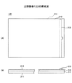
図5は上部基板122の構成図を示す。
[Upper board 122]
FIG. 5 shows a configuration diagram of the
上部基板122は、フィルム基板181、透明抵抗膜182、電極183から構成されている。
The
フィルム基板181は、例えば、PETなどの可撓性を有する樹脂フィルムから構成されている。フィルム基板181の下部基板121に対向する側の面には、その全面にわたって透明抵抗膜182が形成されている。透明抵抗膜182は、ITOなどの透明導電材から構成されている。電極183は、上部基板122の透明抵抗膜182上、矢印X1方向の端部に配置されており、コンタクト184を介して下部基板121に接続されたFPCケーブル124の第5の配線124b−5に接続されている。この上部基板122の電位をインタフェースボード112により検出することにより座標位置が検出される。
The film substrate 181 is made of a flexible resin film such as PET. A transparent resistance film 182 is formed on the entire surface of the film substrate 181 facing the
〔動作〕
図6はインタフェースボード112の処理フローチャート、図7は下部基板121の電位分布を示す図を示す。図7(A)はX座標検出時、図7(B)はY座標検出時の電位分布を示す。
[Operation]
FIG. 6 is a process flowchart of the
インタフェースボード112は、ステップS1−1で第1の配線136−1及び第2の配線136−2に電圧Vxを印加し、第3の配線136−3、第4の配線136−4を接地する。これによって、透明抵抗膜132に、図7(A)に破線で示すような均等な電界分布を発生させることができる。なお、従来の電位分布は、図5(A)に一点鎖線で示すように歪んでいた。よって、本実施例によれば、正確なX座標検出が可能となる。
In step S1-1, the
インタフェースボード112は、ステップS1−2で上部基板122の電位を検出し、ステップS1−3で上部基板122の電位に応じてX座標を検出する。
The
次に、インタフェースボード112は、ステップS1−4で第1の配線136−1及び第4の配線136−4に電圧Vyを印加し、第2の配線136−2、第3の配線136−3を接地する。これによって、透明抵抗膜132に、図7(B)に破線で示すような均等な電界分布を発生させることができる。なお、従来の電位分布は、図7(B)に一点鎖線で示すように歪んでいた。よって、本実施例によれば、正確なY座標検出が可能となる。
Next, the
インタフェースボード112はステップS1−5で上部基板122の電位を検出し、ステップS1−6で上部基板122の電位に応じてY座標を検出する。
The
〔効果〕
本実施例によれば、共通電極134上に配線136−1〜136−4を積層した構成とされているため、パネル部121を狭額化することができる。
〔effect〕
According to the present embodiment, since the wirings 136-1 to 136-4 are stacked on the
また、開口部141により下部基板121の透明抵抗膜132に、X軸座標検出時又はY座標検出時に印加される電位分布を検出領域で均等にできるため、正確な座標検出可能となる。
In addition, since the potential distribution applied to the
〔第1変形例〕
本変形例は下部基板121の構成が第1実施例とは相違している。
[First Modification]
In this modification, the configuration of the
図8は下部基板121の第1変形例の構成図を示す。
FIG. 8 shows a configuration diagram of a first modification of the
本変形例の下部基板311は、開口部141に、Agなどの低抵抗材料からなる低抵抗層321を形成した構成とされている。これによって、透明抵抗膜132と共通電極135とが低抵抗層321を介して接続される。よって、透明抵抗膜132との接触を安定化することができる。
The
また、透明抵抗膜132との接触を安定化することにより、共通電極135の抵抗値を高めることができる。よって、消費電流を低減できるため、消費電力を低減できるようになる。
Further, by stabilizing the contact with the
〔第2変形例〕
本変形例は下部基板121の構成が第1変形例とは相違している。
[Second Modification]
This modification is different from the first modification in the configuration of the
図9は下部基板121の第1変形例の構成図を示す。
FIG. 9 shows a configuration diagram of a first modification of the
本変形例の下部基板411は、共通電極421の形状が第1実施例とは相違している。本変形例の共通電極421は、開口部141の間で外周側に折曲された構成とされている。共通電極421を折曲することにより共通電極421の距離が稼げるため、共通電極421の抵抗を大きくできる。これによって、よって、消費電流を低減できるため、消費電力を低減できるようになる。
In the
〔第3変形例〕
本変形例は下部基板411の構成が第2変形例とは相違している。
[Third Modification]
In this modification, the configuration of the
図10は下部基板121の第3変形例の構成図を示す。
FIG. 10 shows a configuration diagram of a third modification of the
本変形例の下部基板511は、第2の変形例において、開口部141に、Agなどの低抵抗材料からなる低抵抗層521を形成した構成とされている。これによって、透明抵抗膜132と共通電極135とが低抵抗層321を介して接続される。よって、透明抵抗膜132との接触を安定化することができる。
In the second modification, the
また、透明抵抗膜132との接触を安定化することにより、共通電極421の抵抗値を高めることができる。よって、消費電流を低減できるため、消費電力を低減できるようになる。
Further, by stabilizing the contact with the
〔その他〕
なお、上記実施例では、5線式抵抗膜方式アナログタッチパネルについて説明したが、これに限定されるものではなく、4線式抵抗膜方式、7線式抵抗膜方式などの他のタッチパネルにも適用可能である。
[Others]
In the above embodiment, the 5-wire resistive film type analog touch panel has been described. However, the present invention is not limited to this, and is applicable to other touch panels such as a 4-wire resistive film system and a 7-wire resistive film system. Is possible.
〔製造工程〕
次に下部基板121の製造プロセスについて説明する。
〔Manufacturing process〕
Next, a manufacturing process of the
図11は下部基板121の製造プロセスを説明するための図を示す。
FIG. 11 is a diagram for explaining a manufacturing process of the
まず、図11(A)に示すようにガラス基板131上にITOなどの透明抵抗膜132をスパッタリング、真空蒸着によって形成する。
First, as shown in FIG. 11A, a
次に、図11(B)に示すように開口部141を有する第1の絶縁膜133をパターン印刷し、ベークする。
Next, as shown in FIG. 11B, the first insulating
次に、図11(C)に示すように第1の絶縁膜133上にAgCからなる共通電極134を印刷し、ベークする。このとき、開口部141も共通電極134が形成され、共通電極134が開口部141を介して透明抵抗膜132に接続される。
Next, as shown in FIG. 11C, a
次に、図11(D)に示すように第1〜第4の貫通孔151−1〜151−4を有する第2の絶縁膜135をパターン印刷し、ベークする。
Next, as shown in FIG. 11D, the second
次に、図11(E)に示すように第2の絶縁膜135上にAgからなる第1乃至第4の配線136−1〜136−4をパターン印刷し、ベークする。次に、図11(F)に示すように第3の絶縁膜137をパターン印刷し、ベークする。
Next, as shown in FIG. 11E, first to fourth wirings 136-1 to 136-4 made of Ag are pattern printed on the second
以上により下部基板121が完成する。
Thus, the
なお、開口部141に銀などの低抵抗材料からなる低抵抗層321を形成する場合には、図11(B)に示す工程の後に、銀などの低抵抗材料を開口部141に対応する部分に印刷し、ベークする。
Note that in the case where the low-
100 座標入力システム
111 パネル部、112 インタフェースボード
121 下部基板、122 上部基板、123 スペーサ、124 FPCケーブル
131 ガラス基板、132 透明抵抗膜、133 第1の絶縁膜、134 共通電極
135 第2の絶縁膜、136−1〜136−4 配線、137 第3の絶縁膜
100 Coordinate
Claims (12)
前記ガラス基板の全面に形成されている抵抗膜と、
該抵抗膜に電圧を印加する共通電極と、
該共通電極に電圧を印加する電圧供給部とを有し、該電圧供給部から該共通電極に電圧を印加し、該共通電極から該抵抗膜に電位を供給することにより、該抵抗膜に電位分布を発生させ、前記抵抗膜の接触位置の電位を検出することにより、前記抵抗膜の接触位置座標を検出する座標検出装置であって、
前記共通電極と前記抵抗膜との間に配置され、前記ガラス基板の周縁部の全周にわたって長方形状に形成され、前記共通電極から前記抵抗膜に電位を供給する電位供給部が形成された共通電極−抵抗膜間絶縁膜を有し、
前記電位供給部は、前記共通電極−抵抗膜間絶縁膜の全周に断続的に形成された開口から構成されており、
前記共通電極は、前記抵抗膜上に、前記開口を埋めるように形成されており、
前記開口は、前記共通電極−抵抗膜間絶縁膜の各辺の中央部では直線形状であり、前記共通電極−抵抗膜間絶縁膜の各辺の両端部では内周方向に湾曲した形状であることを特徴とする座標検出装置。 A glass substrate;
A resistance film formed on the entire surface of the glass substrate ;
A common electrode for applying a voltage to the resistive film;
A voltage supply unit for applying a voltage to the common electrode, applying a voltage from the voltage supply unit to the common electrode, and supplying a potential from the common electrode to the resistance film, thereby providing a potential to the resistance film. A coordinate detection device that detects a contact position coordinate of the resistive film by generating a distribution and detecting a potential of the resistive film contact position,
The common electrode is disposed between the common electrode and the resistance film, is formed in a rectangular shape over the entire circumference of the peripheral edge of the glass substrate, and is formed with a potential supply unit that supplies a potential from the common electrode to the resistance film. Having an insulating film between the electrode and the resistance film;
The potential supply unit, prior Symbol common electrode - the entire periphery of the resistive film between the insulating film is composed of intermittently-formed opening,
The common electrode is formed on the resistive film so as to fill the opening,
The opening has a linear shape at the center of each side of the common electrode-resistive insulating film, and has a shape curved in the inner circumferential direction at both ends of each side of the common electrode-resistive insulating film. A coordinate detection apparatus characterized by that.
前記ガラス基板の全面に形成されている抵抗膜と、
該抵抗膜に電圧を印加する共通電極と、
該共通電極に電圧を印加する電圧供給部と、
該電圧供給部に電圧を供給する配線とを有し、該配線により該電圧供給部に電圧を供給し、該電圧供給部から該共通電極に電圧を印加し、該共通電極から該抵抗膜に電位を供給することにより、該抵抗膜に電位分布を発生させ、前記抵抗膜の接触位置の電位を検出することにより、前記抵抗膜の接触位置座標を検出する座標検出装置であって、
前記配線は、配線−共通電極間絶縁膜を介して前記共通電極上に積層して配置された構成とされており、
前記共通電極と前記抵抗膜との間に配置され、前記ガラス基板の周縁部の全周にわたって長方形状に形成され、前記共通電極から前記抵抗膜に電位を供給する電位供給部が形成された共通電極−抵抗膜間絶縁膜を有し、
前記配線−共通電極間絶縁膜は、前記共通電極−抵抗膜間絶縁膜上に前記共通電極を覆うように形成され、
前記電位供給部は、前記共通電極−抵抗膜間絶縁膜の全周に断続的に形成された開口から構成されており、
前記共通電極は、前記抵抗膜上に、前記開口を埋めるように形成されており、
前記開口は、前記共通電極−抵抗膜間絶縁膜の各辺の中央部では直線形状であり、前記共通電極−抵抗膜間絶縁膜の各辺の両端部では内周方向に湾曲した形状であることを特徴とする座標検出装置。 A glass substrate;
A resistance film formed on the entire surface of the glass substrate ;
A common electrode for applying a voltage to the resistive film;
A voltage supply unit for applying a voltage to the common electrode;
Wiring for supplying a voltage to the voltage supply unit, supplying a voltage to the voltage supply unit through the wiring, applying a voltage from the voltage supply unit to the common electrode, and supplying the voltage from the common electrode to the resistance film A coordinate detection device for detecting a contact position coordinate of the resistance film by generating a potential distribution in the resistance film by supplying a potential and detecting a potential of the contact position of the resistance film;
The wiring is configured to be laminated on the common electrode via a wiring-common electrode insulating film,
The common electrode is disposed between the common electrode and the resistance film, is formed in a rectangular shape over the entire circumference of the peripheral edge of the glass substrate, and is formed with a potential supply unit that supplies a potential from the common electrode to the resistance film. electrode - have a resistive film insulating film,
The wiring-common electrode insulating film is formed on the common electrode-resistive film insulating film so as to cover the common electrode,
The potential supply unit, prior Symbol common electrode - the entire periphery of the resistive film between the insulating film is composed of intermittently-formed opening,
The common electrode is formed on the resistive film so as to fill the opening,
The opening has a linear shape at the center of each side of the common electrode-resistive insulating film, and has a shape curved in the inner circumferential direction at both ends of each side of the common electrode-resistive insulating film. A coordinate detection apparatus characterized by that.
前記駆動電極−抵抗膜絶縁膜は、前記駆動電極から前記抵抗膜に駆動電圧を印加する駆動電圧印加部を有することを特徴とする請求項1〜11何れかに記載の座標検出装置。
A drive electrode-resistive film insulating film provided between the drive electrode and the resistance film and insulating the drive electrode and the resistance film;
The coordinate detection device according to claim 1, wherein the drive electrode-resistive film insulating film includes a drive voltage application unit that applies a drive voltage from the drive electrode to the resistance film.
Priority Applications (2)
| Application Number | Priority Date | Filing Date | Title |
|---|---|---|---|
| JP2005204778A JP4718920B2 (en) | 2005-07-13 | 2005-07-13 | Coordinate detection device |
| US11/442,223 US7825906B2 (en) | 2005-07-13 | 2006-05-30 | Coordinate detecting device |
Applications Claiming Priority (1)
| Application Number | Priority Date | Filing Date | Title |
|---|---|---|---|
| JP2005204778A JP4718920B2 (en) | 2005-07-13 | 2005-07-13 | Coordinate detection device |
Publications (2)
| Publication Number | Publication Date |
|---|---|
| JP2007025904A JP2007025904A (en) | 2007-02-01 |
| JP4718920B2 true JP4718920B2 (en) | 2011-07-06 |
Family
ID=37661243
Family Applications (1)
| Application Number | Title | Priority Date | Filing Date |
|---|---|---|---|
| JP2005204778A Expired - Fee Related JP4718920B2 (en) | 2005-07-13 | 2005-07-13 | Coordinate detection device |
Country Status (2)
| Country | Link |
|---|---|
| US (1) | US7825906B2 (en) |
| JP (1) | JP4718920B2 (en) |
Families Citing this family (25)
| Publication number | Priority date | Publication date | Assignee | Title |
|---|---|---|---|---|
| US7663607B2 (en) | 2004-05-06 | 2010-02-16 | Apple Inc. | Multipoint touchscreen |
| US7683891B2 (en) * | 2005-12-22 | 2010-03-23 | Synaptics Incorporated | Equalizing reference surface capacitance with uneven thickness |
| CN104965621B (en) * | 2006-06-09 | 2018-06-12 | 苹果公司 | Touch screen LCD and its operating method |
| US8243027B2 (en) * | 2006-06-09 | 2012-08-14 | Apple Inc. | Touch screen liquid crystal display |
| KR102125605B1 (en) | 2006-06-09 | 2020-06-22 | 애플 인크. | Touch screen liquid crystal display |
| US8493330B2 (en) * | 2007-01-03 | 2013-07-23 | Apple Inc. | Individual channel phase delay scheme |
| US9710095B2 (en) | 2007-01-05 | 2017-07-18 | Apple Inc. | Touch screen stack-ups |
| TWI387915B (en) * | 2007-11-20 | 2013-03-01 | Tpk Touch Solutions Inc | Method for detecting touch points of touch device |
| JP2009199145A (en) * | 2008-02-19 | 2009-09-03 | Young Fast Optoelectronics Co Ltd | Signal conduction structure of touch panel |
| EP2261783A4 (en) * | 2008-03-31 | 2013-05-22 | Sharp Kk | Display device, electronic device provided with the display device, and touch panel |
| JP4996531B2 (en) | 2008-04-23 | 2012-08-08 | 富士通コンポーネント株式会社 | Coordinate detection device |
| JP2009274104A (en) | 2008-05-15 | 2009-11-26 | Fujitsu Component Ltd | Apparatus for producing coordinate detector |
| JP5086886B2 (en) | 2008-05-15 | 2012-11-28 | 富士通コンポーネント株式会社 | Method for manufacturing coordinate detection apparatus |
| JP2009277047A (en) * | 2008-05-15 | 2009-11-26 | Fujitsu Component Ltd | Coordinate detector |
| JP5065152B2 (en) | 2008-05-19 | 2012-10-31 | 富士通コンポーネント株式会社 | Method for manufacturing coordinate detection apparatus |
| JP5307447B2 (en) * | 2008-05-19 | 2013-10-02 | 富士通コンポーネント株式会社 | Method for manufacturing coordinate detection apparatus |
| JP4968380B2 (en) | 2010-03-03 | 2012-07-04 | カシオ計算機株式会社 | Contact state detection method, touch panel device, and display device |
| US8804056B2 (en) * | 2010-12-22 | 2014-08-12 | Apple Inc. | Integrated touch screens |
| JP5757800B2 (en) | 2011-06-24 | 2015-08-05 | 富士通コンポーネント株式会社 | Touch panel |
| US9253892B2 (en) * | 2012-04-13 | 2016-02-02 | Wistron Corporation | Peripheral circuit of touch panel and manufacturing method thereof |
| KR102035005B1 (en) * | 2012-12-24 | 2019-10-22 | 엘지디스플레이 주식회사 | Touch display device |
| CN103336598B (en) * | 2013-06-07 | 2016-06-08 | 业成光电(深圳)有限公司 | Touch control display apparatus |
| CN104503619B (en) * | 2014-12-31 | 2017-09-05 | 深圳市华星光电技术有限公司 | The manufacture method and touch-screen of a kind of array base palte |
| KR101652029B1 (en) * | 2015-04-13 | 2016-08-30 | 주식회사 하이딥 | Pressure detection module and smartphone including the same |
| JP7527082B2 (en) | 2020-12-10 | 2024-08-02 | Fclコンポーネント株式会社 | Touch Panel |
Citations (1)
| Publication number | Priority date | Publication date | Assignee | Title |
|---|---|---|---|---|
| JPH03109487U (en) * | 1990-02-22 | 1991-11-11 |
Family Cites Families (11)
| Publication number | Priority date | Publication date | Assignee | Title |
|---|---|---|---|---|
| US4661655B1 (en) * | 1984-12-24 | 1997-01-21 | Elographics Inc | Electrographic touch sensor and method of reducing bowed equipotential fields therein |
| US4797514A (en) * | 1986-06-09 | 1989-01-10 | Elographics, Inc. | Touch sensitive device with increased linearity |
| US4725695A (en) * | 1986-11-10 | 1988-02-16 | Tektronix, Inc. | Touch panel with discontinuities in touch sensitive surface |
| JPH0546306A (en) * | 1991-08-19 | 1993-02-26 | Fujitsu Ltd | Coordinate input device |
| JPH09146682A (en) * | 1995-11-29 | 1997-06-06 | Fujitsu Takamizawa Component Kk | Coordinate input device |
| JP3799639B2 (en) * | 1995-12-11 | 2006-07-19 | 富士通コンポーネント株式会社 | Coordinate input device |
| JP3984670B2 (en) | 1996-09-06 | 2007-10-03 | 富士通コンポーネント株式会社 | Coordinate detection device |
| US6512512B1 (en) * | 1999-07-31 | 2003-01-28 | Litton Systems, Inc. | Touch panel with improved optical performance |
| JP2001125724A (en) | 1999-10-27 | 2001-05-11 | Finput Co Ltd | Touch panel |
| US6488981B1 (en) * | 2001-06-20 | 2002-12-03 | 3M Innovative Properties Company | Method of manufacturing a touch screen panel |
| JP2003288166A (en) * | 2002-03-27 | 2003-10-10 | Fujitsu Component Ltd | Connection structure between touch panel and external lead wire |
-
2005
- 2005-07-13 JP JP2005204778A patent/JP4718920B2/en not_active Expired - Fee Related
-
2006
- 2006-05-30 US US11/442,223 patent/US7825906B2/en not_active Expired - Fee Related
Patent Citations (1)
| Publication number | Priority date | Publication date | Assignee | Title |
|---|---|---|---|---|
| JPH03109487U (en) * | 1990-02-22 | 1991-11-11 |
Also Published As
| Publication number | Publication date |
|---|---|
| US7825906B2 (en) | 2010-11-02 |
| JP2007025904A (en) | 2007-02-01 |
| US20070013678A1 (en) | 2007-01-18 |
Similar Documents
| Publication | Publication Date | Title |
|---|---|---|
| JP4718920B2 (en) | Coordinate detection device | |
| JP4996531B2 (en) | Coordinate detection device | |
| CN101819495B (en) | Patterned substrate, touch screen sensor assembly having the same and manufacturing method thereof | |
| JP5086886B2 (en) | Method for manufacturing coordinate detection apparatus | |
| US9639229B2 (en) | Display device with touch panel | |
| US10642391B2 (en) | Touch panel and display device | |
| US20070103446A1 (en) | Wiring of touch panel | |
| JP2013225266A (en) | Touch panel | |
| JP5065152B2 (en) | Method for manufacturing coordinate detection apparatus | |
| KR102335116B1 (en) | Touch screen pannel and manufacturing method thereof | |
| JP5784959B2 (en) | Touch panel | |
| KR101077674B1 (en) | Coordinate detecting device | |
| JP2009274104A (en) | Apparatus for producing coordinate detector | |
| JP5307447B2 (en) | Method for manufacturing coordinate detection apparatus | |
| JP5265054B2 (en) | Touch panel | |
| KR101037643B1 (en) | Coordinate detector | |
| KR101118809B1 (en) | Wiring of touch panel | |
| KR100300433B1 (en) | Touch panel | |
| KR101049327B1 (en) | Wiring structure of touch panel | |
| JP4772460B2 (en) | Contact control panel wiring structure | |
| JP2005078491A (en) | Apparatus of transparent touch panel | |
| EP1785822A1 (en) | Wiring of touch panel | |
| AU2005232310A1 (en) | Wiring of touch panel | |
| JPS62154015A (en) | Analog input device |
Legal Events
| Date | Code | Title | Description |
|---|---|---|---|
| A621 | Written request for application examination |
Free format text: JAPANESE INTERMEDIATE CODE: A621 Effective date: 20080509 |
|
| A977 | Report on retrieval |
Free format text: JAPANESE INTERMEDIATE CODE: A971007 Effective date: 20100218 |
|
| A131 | Notification of reasons for refusal |
Free format text: JAPANESE INTERMEDIATE CODE: A131 Effective date: 20100223 |
|
| A521 | Written amendment |
Free format text: JAPANESE INTERMEDIATE CODE: A523 Effective date: 20100423 |
|
| A131 | Notification of reasons for refusal |
Free format text: JAPANESE INTERMEDIATE CODE: A131 Effective date: 20101005 |
|
| A521 | Written amendment |
Free format text: JAPANESE INTERMEDIATE CODE: A523 Effective date: 20101101 |
|
| TRDD | Decision of grant or rejection written | ||
| A01 | Written decision to grant a patent or to grant a registration (utility model) |
Free format text: JAPANESE INTERMEDIATE CODE: A01 Effective date: 20110329 |
|
| A01 | Written decision to grant a patent or to grant a registration (utility model) |
Free format text: JAPANESE INTERMEDIATE CODE: A01 |
|
| A61 | First payment of annual fees (during grant procedure) |
Free format text: JAPANESE INTERMEDIATE CODE: A61 Effective date: 20110401 |
|
| R150 | Certificate of patent or registration of utility model |
Free format text: JAPANESE INTERMEDIATE CODE: R150 |
|
| FPAY | Renewal fee payment (event date is renewal date of database) |
Free format text: PAYMENT UNTIL: 20140408 Year of fee payment: 3 |
|
| R250 | Receipt of annual fees |
Free format text: JAPANESE INTERMEDIATE CODE: R250 |
|
| R250 | Receipt of annual fees |
Free format text: JAPANESE INTERMEDIATE CODE: R250 |
|
| S531 | Written request for registration of change of domicile |
Free format text: JAPANESE INTERMEDIATE CODE: R313531 |
|
| R350 | Written notification of registration of transfer |
Free format text: JAPANESE INTERMEDIATE CODE: R350 |
|
| R250 | Receipt of annual fees |
Free format text: JAPANESE INTERMEDIATE CODE: R250 |
|
| R250 | Receipt of annual fees |
Free format text: JAPANESE INTERMEDIATE CODE: R250 |
|
| LAPS | Cancellation because of no payment of annual fees |