JP4711526B2 - Light diffusion sheet - Google Patents
Light diffusion sheet Download PDFInfo
- Publication number
- JP4711526B2 JP4711526B2 JP2001053537A JP2001053537A JP4711526B2 JP 4711526 B2 JP4711526 B2 JP 4711526B2 JP 2001053537 A JP2001053537 A JP 2001053537A JP 2001053537 A JP2001053537 A JP 2001053537A JP 4711526 B2 JP4711526 B2 JP 4711526B2
- Authority
- JP
- Japan
- Prior art keywords
- light diffusion
- light
- diffusion sheet
- binder
- ultrafine particles
- Prior art date
- Legal status (The legal status is an assumption and is not a legal conclusion. Google has not performed a legal analysis and makes no representation as to the accuracy of the status listed.)
- Expired - Lifetime
Links
Images


Landscapes
- Optical Elements Other Than Lenses (AREA)
- Liquid Crystal (AREA)
- Laminated Bodies (AREA)
- Compositions Of Macromolecular Compounds (AREA)
Description
【0001】
【発明の属する技術分野】
本発明は、液晶表示装置のバックライトユニットに組み込まれる光拡散シートの性能改善と、これを用いたバックライトユニットに関する。
【0002】
【従来の技術および発明が解決しようとする課題】
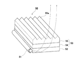
液晶表示装置は、液晶層を背面から照らして発光させるバックライト方式が普及し、液晶層の下面側にはバックライトユニットが装備されている。 かかるバックライトユニット50は、一般的には、図4に示すように、光源としての棒状のランプ51と、このランプ51に端部が沿うように配置される方形板状の導光板52、それに、この導光板52の表面側に積層された複数枚の光学シート53とを装備している。 この光学シート53は、それぞれ、屈折、拡散等の特定の光学的性質を有するものであり、具体的には、導光板52の表面側に配設される光拡散シート54、光拡散シート54の表面側に配設されるプリズムシート55などが該当する。
【0003】
このバックライトユニット50の機能を説明すると、まず、ランプ51より導光板52に入射した光線は、導光板52裏面の反射ドットまたは反射シート(図示せず)、それに各側面で反射され、導光板52表面から出射される。 導光板52から出射した光線は光拡散シート54に入射し、拡散され、光拡散シート54表面より出射される。 その後、光拡散シート54から出射された光線は、プリズムシート55に入射し、プリズムシート55の表面に形成されたプリズム部55aによって、略真上方向にピークを示す分布の光線として出射される。 このように、ランプ51から出射された光線が、光拡散シート54によって拡散され、またプリズムシート55によって略真上方向にピークを示すように屈折され、さらに上方の液晶層全面(図示せず)を照明するものである。
【0004】
また、図示はしていないが、上述のプリズムシート55の集光特性を考慮し、プリズムシート55の表面側にさらに光拡散シートやプリズムシートを配設する構成のバックライトユニットもある。
【0005】
上述の構造を有するバックライトユニット50での光拡散シート54としては、図5に示すような、基材シート56と光拡散層57とが積層されたものが一般的に用いられており、光拡散層57は合成樹脂からなるバインダー58内に、合成樹脂、ガラス等からなるビーズ59が分散した構造を有している。
【0006】
ところで、一般的に、光拡散シート54は合成樹脂で形成されているため、熱による変形を受けやすいという欠点を有している。 一方、光線発生源であるランプ51は発光と同時に発熱する。 一般的には、光拡散シート54のランプ51近傍部分は、80℃から90℃程度の温度下に曝されるため、光拡散シート54が熱変形を起こして部分的に撓みが生じ、その結果、画面の輝度ムラが発生してしまうという問題がある。
【0007】
この点を改善すべく、これまでに、光拡散シート54での光拡散層57のバインダー58内に無機微粒子を分散含有させることで、耐熱性の向上を図る技術が開発されている(例えば、特開平7−5305号公報参照)が、無機微粒子の分散性が悪く、十分な耐熱性を得ることができない上に、無機微粒子とバインダー58との密着性が不十分で、両者の界面に微小な隙間が生じ、強度及び光線の透過性が低下するなどの問題点が未解決のままである。
【0008】
【課題を解決するための手段】
本発明は、従来技術でのこれら不都合に鑑みてなされたものであり、その要旨とするところは、透明な基材シート、及び基材シートの表面に積層され、かつそのバインダー内にビーズと平均粒径5nm以上100nm以下の無機超微粒子が分散してなる光拡散層を含む光拡散シートにおいて、無機超微粒子が、その表面に有機化合物が固定されており、かつ光拡散層のバインダーが、電離放射線硬化型樹脂を含む樹脂から形成さる光拡散シートにある。本発明の構成により、その透明性を維持しつつ、耐熱性及び熱的寸法安定性を向上させることができ、ランプの発熱によっても撓みが発生しにくい光拡散シート、及び、かかる光拡散シートを用いて輝度ムラの発生を低減するバックライトユニットが提供される。
【0009】
無機超微粒子の表面に固定される有機化合物としては、後述するような、バインダーを構成する有機マトリックスに対する親和性や、表面硬度、耐熱性、耐摩耗性、耐候性、耐汚染性等に関する被膜物性の良い光拡散層を得る観点からして、重合性官能基および/またはアルコキシ基を有する有機化合物とすることが望ましい。 ところで、本明細書で使用する「固定」なる用語は、単なる接着および付着を意味するものではなく、有機化合物、特に、重合性官能基および/またはアルコキシ基を有する有機化合物と無機微粒子の間で化学結合が生成していることを意味するものである。 従って、無機微粒子を任意の溶剤で洗った洗液からは、有機化合物が検出されない。
【0010】
本発明の光拡散シートによれば、無機超微粒子が光拡散層に分散含有されているので、光拡散層の見かけ上の結晶化度を上昇させ、耐熱性を高めることができ、その結果、光拡散シートの熱による撓みの発生を抑えることができる。 また、耐熱性の向上のために分散含有させるものが超微粒子であるため、透明性を阻害する度合いが少ない。 さらに、バインダー内に分散させる無機超微粒子は、その表面に有機化合物が固定されている。 これにより、バインダーを構成する有機マトリックスに対して良好な親和性を有し、表面硬度、耐熱性、耐摩耗性、耐候性、耐汚染性等の被膜物性の良い光拡散層を形成することができる。 さらに、バインダーが、電離放射線硬化型樹脂を含む樹脂から形成されているので、光拡散層に電子線や光線などを照射することで、その硬化形成処理が容易かつ迅速に実現され、光拡散シートの製造効率の改善が期待される。
【0011】
また、本発明の光拡散シートのその他の態様によれば、透明な基材シートの他方の面(つまり、光拡散層が設けられていない面)に、スティッキング防止層をさらに具備した光拡散シートが提供される。 このスティッキング防止層とは、バインダー単独の層またはバインダー内にビーズと無機超微粒子とが分散した層であり、この無機超微粒子の表面に有機化合物が固定されており、好ましくは、バインダーは、電離放射線硬化型樹脂を含む樹脂から形成する。 本発明のこの態様での光拡散シートによれば、上述の光拡散層と同様に、スティッキング防止層の見かけ上の結晶化度を上昇させて耐熱性を高めることができ、その結果、光拡散シート全体の撓みを抑えることができる。 また、光拡散層と同様に、バインダーと無機超微粒子との親和性が高いので、表面硬度、耐候性等の高いスティッキング防止層を形成することができる。 さらに、バインダーを、電離放射線硬化型樹脂を含む樹脂から形成することで、光拡散層と同時に、スティッキング防止層に電子線や光線などを照射すると、その硬化形成処理が容易かつ迅速に実現され、光拡散シートの製造効率の改善が期待される。
【0012】
電離放射線硬化型樹脂としては、電子線硬化型樹脂や紫外線硬化型樹脂などが知られているが、その入手容易性や取り扱い容易性の観点からすれば、紫外線硬化型樹脂が好ましい。
【0013】
有機化合物としては、重合性官能基および/またはアルコキシ基を有する有機化合物が好ましい。 こうすることで、バインダーと有機化合物とが架橋構造によって結合されるので、保存安定性、耐汚染性、可撓性、耐候性、保存安定性等の良好な被膜物性の塗膜を与えることができ、得られる被膜も光沢があるため好ましい。 また、有機化合物が固定された無機超微粒子内に、重合性官能基および/またはアルコキシ基を、0.01〜50mmol/g含有するとよい。 これはすなわち、無機超微粒子に固定する有機化合物にこの程度の濃度で重合性官能基および/またはアルコキシ基を含有させることで、無機超微粒子とバインダーを構成する有機マトリックスとの親和性や、有機マトリックス内での無機超微粒子の分散性を向上させる作用がある。 さらに、バインダーとの架橋構造の形成をさらに促す観点から、有機化合物を、有機ポリマーとするとよい。
【0014】
また、無機超微粒子としては、その平均粒径が5〜100nmのものを使用する。
【0015】
これはすなわち、平均粒径をこの範囲にすると、無機超微粒子が可視光の波長より小さく、透明性を完全に維持することができることによる。 また、無機超微粒子として、コロイダルシリカを用いるとよい。 コロイダルシリカによれば、光拡散層を形成する樹脂組成物の攪拌を中断しても、この樹脂組成物の粘度を大幅に上昇させることが無く、樹脂組成物の調製作業や塗工作業が容易となる。
【0016】
さらに、無機超微粒子の配合量としては、バインダー中のポリマー分100部に対して10〜200部の量が好ましい。 ここで、「部」で示す数値は、質量を基準とした比を意味する。 かかる範囲の配合量とすることで、透明性や強度などの光拡散シートとして必要な機能を維持しつつ、上述の耐熱性及び熱的寸法安定性の向上作用を十分に達成することができる。
【0017】
そして、ランプと、このランプから発せられる光線を表面側へ導く略方形板状の導光板と、この導光板の表面側に配設される光拡散シートとを装備する液晶表示装置用のバックライトユニットにおいて、本発明の光拡散シートを用いると、光拡散シートの熱による撓みが少ないため、液晶表示装置の輝度ムラを抑えることができる。
【0018】
【発明の実施の形態】
以下、適宜図面を参照しつつ本発明の実施の形態を詳説する。
【0019】
図1は、本発明の一実施形態に係る光拡散シートを示す模式的断面図であり、光拡散シート1は、基材シート3と、この基材シート3の表面に積層された光拡散層5とから構成されている。
【0020】
基材シート3は、光線を透過させる必要があるので透明、特に、無色透明のものであれば特に限定されるものではなく、例えば、ポリエチレンテレフタレート、ポリエチレンナフタレート、アクリル樹脂、ポリカーボネート、ポリスチレン、ポリオレフィン、セルロースアセテート、耐候性塩化ビニル等の合成樹脂から形成されている。 基材シート3の厚みは特には限定されないが、例えば、50〜250μmとされる。 これはすなわち、基材シート3の厚みがこの範囲に満たないと、光拡散層5を形成する樹脂組成物を塗工した際にカールが発生しやすくなってしまうことがある。 逆に、基材シート3の厚みがこの範囲より大きくなると、液晶表示装置の輝度が低下してしまうことがあり、また、バックライトユニットの厚みが大きくなって液晶表示装置の薄型化の要求に反することにもなる。
【0021】
光拡散層5は、電離放射線硬化型樹脂を含む樹脂から形成されたバインダー7、このバインダー7内に分散するビーズ9および無機超微粒子11から構成されている。 無機超微粒子11の分散により、光拡散シート1の見かけ上の結晶化度を上昇させ、光拡散シート1の耐熱性を高めることができ、その撓みを抑えることができる。 また、光拡散層5にビーズ9を分散させることにより、この光拡散層5を裏側から表側に透過する光線を均一に拡散させることができる。 さらに、ビーズ9の一部は、その上端がバインダー7から突出している。 このようにバインダー7に埋設されているビーズ9と突出しているビーズ9とを設けることにより、光線をより均質に拡散させることができる。 光拡散層5の厚み(ビーズ9を除いたバインダー7部分の厚みであり、図1においてT1で表した)は、特には限定されないが、例えば、10〜30μm以下程度とされている。
【0022】
無機超微粒子11を分散させることにより光拡散シート1の見かけ上の結晶化度を上昇させることができる理由は詳細には不明であるが、無機超微粒子11が結晶性高分子の結晶部分と同様の挙動を示し、バインダーに用いられる高分子の分子鎖の熱的運動を妨げるためと推定される。
【0023】
ビーズ9は略球形であり、その材質としては、例えば、アクリル樹脂、ポリウレタン、ポリ塩化ビニル、ポリスチレン、ポリアクリロニトリル、ポリアミド等が挙げられる。 ビーズ9は、光拡散シート1を透過する光線量を多くする観点からして透明とするのが好ましく、特に、無色透明とするのが好ましい。
【0024】
ビーズ9の平均粒径は、1〜50μmが好ましく、2〜20μmが特に好ましい。 これはすなわち、平均粒径がこの範囲に満たないと、光拡散効果が不十分となってしまうことがある。 逆に、平均粒径がこの範囲より大きくなると、光拡散層5を形成する樹脂組成物の塗工が困難となってしまうことがある。
【0025】
光拡散層5におけるビーズ9の配合量は、バインダー7中のポリマー分100重量部に対して10〜500重量部が好ましく、10〜300重量部が特に好ましい。 これはすなわち、配合量がこの範囲に満たないと、光拡散効果が不十分となってしまうことがある。 逆に、配合量が上記範囲より大きくなると、光拡散層5を形成する樹脂組成物の塗工が困難となってしまうことがある。
【0026】
バインダー7を構成する素材としては、例えば、アクリル系樹脂、ポリウレタン、ポリエステル、フッ素系樹脂、シリコーン系樹脂、ポリアミドイミド、エポキシ樹脂等のポリマーが挙げられる。 これらの中でも、(メタ)アクリル系樹脂、(メタ)アクリル−スチレン系樹脂、(メタ)アクリル−ポリエステル系樹脂等の(メタ)アクリル単位を含む有機ポリマーを必須成分とするポリマーが好適である。 またバインダー7には、上記ポリマーの他、例えば、可塑剤、安定化剤、劣化防止剤、分散剤、帯電防止剤等が配合されてもよい。 なお、バインダー7は、光線を透過させる必要があるので透明とされており、特に、無色透明とするのが好ましい。
【0027】
ところで、 本発明の態様によれば、上記ポリマーの他に、バインダー7の構成成分として電離放射線硬化型樹脂を必須成分として含む。 電離放射線硬化型樹脂としては、紫外線硬化型樹脂あるいは電子線硬化型樹脂などが知られており、本発明にあっては、そのいずれもが使用できるが、その入手容易性や取り扱い容易性の観点からすれば、紫外線硬化型樹脂が好ましい。
【0028】
電離放射線硬化型樹脂とは、その分子中に重合性不飽和結合またはエポキシ基をもつ反応性のプレポリマー、オリゴマーおよび/または単量体を適宜混合してなる組成物である。 これらプレポリマーやオリゴマーとしては、ウレタンアクリレート、ポリエステルアクリレート、エポキシアクリレート、シロキサンや不飽和ジカルボン酸と多価アルコールとの縮合物である不飽和ポリエステルがあり、アルキルアクリレートやアルキルメタクリレート、ポリエステルアクリレート、ポリエステルメタクリレート、ポリエーテルアクリレート、ポリエーテルメタクリレート、ポリオールアクリレート、ポリオールメタクリレート、メラミンアクリレート、メラミンメタクリレートなどのアクリレート類が挙げられる。 一方で、単量体としては、スチレン、α−メチルスチレンなどのビニルベンゼンモノマーや、メチルアクリレート、メチルメタアクリレート、エチルアクリレート、エチルメタアクリレート、ブチルアクリレート、ブチルメタアクリレート、2−エチルヘキシルアクリレート、2−エチルヘキシルメタクリレート、メトキシエチルアクリレート、メトキシエチルメタクリレート、ブトキシエチルアクリレート、ブトキシエチルメタクリレート、フェニルアクリレート、フェニルメタクリレートなどがあり、さらに、N−ジメチルアミノエチルアクリレート、N−ジメチルアミノエチルメタクリレート、N−ジエチルアミノエチルアクリレート、N−ジエチルアミノエチルメタクリレート、N−ジベンジルアミノエチルアクリレート、N−ジベンジルアミノエチルメタクリレート、N−ジエチルアミノプロピルアクリレート、N−ジエチルアミノプロピルメタクリレートなどの不飽和カルボン酸とアミノアルコールとのエステルなどがある。 また、アクリルアミド、メタクリルアミドなどの不飽和カルボン酸アミド、エチレングリコールジアクリレート、エチレングリコールジメタクリレート、プロピレングリコールジアクリレート、プロピレングリコールジメタクリレート、ネオペンチルグリコールジアクリレート、ネオペンチルグリコールジメタクリレート、プロピレングリコールジアクリレート、プロピレングリコールジメタクリレート、1,6-ヘキサンジオールアクリレート、1,6-ヘキサンジオールジメタクリレート、トリエチレングリコールジアクリレート、トリエチレングリコールジメタクリレートなどの不飽和カルボン酸とグリコールなどのエステルがある。 さらに、ジプロピレングリコールジアクリレート、ジプロピレングリコールジメタクリレート、エチレングリコールジアクリレート、エチレングリコールジメタクリレート、プロピレングリコールジアクリレート、プロピレングリコールジメタクリレートなどの多官能性化合物、トリメチロールプロパントリチオグリコレート、トリメチロールプロパントリチオプロピレート、ペンタエリスリトールテトラチオグリコレートなどの分子内に2個以上のチオール基をもつポリチオール化合物などがある。
【0029】
電離放射線硬化型樹脂を得るべく、これら化合物の1つ以上を混合して用いるが、通常は、バインダーを塗布してから硬化するまでの所定の保持時間を付与すべく、プレポリマーまたはオリゴマーを5重量%以上、単量体および/またはポリチオールを95重量%以下の量とする。
【0030】
なお、電離放射線硬化型樹脂として、紫外線硬化型樹脂を選択する場合には、光重合開始剤を併用する。 光重合開始剤としては、アセトフェノン類、ベンゾフェノン類、ミヒラーベンゾイルベンゾエート、o−ベンゾイル安息香酸メチル、アルドオキシム、テトラメチルメウラムモノサルファイド、チオキサントン、および/または光増感剤であるn−ブチルアミン、トリエチルアミン、トリブチルホスフィンなどを混合して使用できる。
【0031】
紫外線硬化型樹脂としては、例えば、イルガキュア 651(チバガイギー社)が本発明において好適に使用することができ、また、好ましくは、光重合開始剤であるユニデック17-183(大日本インキ)との組み合わせにおいて利用する。
【0032】
無機超微粒子11とは、任意の元素で構成される無機物の超微粒子であって、その表面に有機化合物が固定されており、バインダー7内での分散性やバインダー7との親和性の向上を図るためのものである。
【0033】
無機超微粒子の表面に固定される有機化合物としては、先述した通り、バインダーを構成する有機マトリックスに対する親和性や、被膜物性の良好な光拡散層を得る観点からして、重合性官能基および/またはアルコキシ基を有する有機化合物とすることが望ましい。これら有機化合物については、その分子量、形状、組成、官能基の有無等に関して特に限定はなく、任意のものを使用することができる。 また、有機化合物の形状については、直鎖状、分枝状、架橋構造等の任意の形状のものを使用することができる。 かかる有機化合物としては、例えば、(メタ)アクリル樹脂、ポリスチレン、ポリ酢酸ビニル、ポリエチレンやポリプロピレン等のポリオレフィン、ポリ塩化ビニル、ポリ塩化ビニリデン、ポリエチレンテレフタレート等のポリエステルおよびこれらの共重合体やアミノ基、エポキシ基、ヒドロキシル基、カルボキシル基等の官能基で一部変性した樹脂等の高分子量の有機化合物(有機ポリマー)が挙げられる。 これらの中でも、(メタ)アクリル系樹脂、(メタ)アクリル−スチレン系樹脂、(メタ)アクリル−ポリエステル系樹脂等の(メタ)アクリル単位を含む有機ポリマーを必須成分とするものが好適である。
【0034】
無機超微粒子11を構成する無機物としては、特に限定されるものではなく、無機酸化物が好ましい。 この無機酸化物は、金属元素が主に酸素原子との結合を介して三次元のネットワークを構成した種々の含酸素金属化合物と定義される。また、無機酸化物を構成する金属元素としては、たとえば、元素周期律表II〜VI族から選ばれる元素が好ましく、元素周期律表III〜V族から選ばれる元素がさらに好ましい。 その中でも、Si、Al、TiおよびZrから選択される元素が特に好ましく、金属元素がSiであるコロイダルシリカが、無機超微粒子として最も好ましい。 また、無機超微粒子11の形状は、球状、針状、板状、鱗片状、破砕状等の任意の粒子形状でよく、特に限定されない。
【0035】
そして、シリコンを金属とするアルコキシ基を含む分子量が比較的小さな有機化合物としては、シランカップリング剤として市販されているものが、本発明において好適に使用できる。 このような化合物として、アルキルトリエトキシシラン、ビニルトリエトキシシラン、γ−アミノプロピルトリエトキシシラン、γ−グリシドキシプロピルトリエトキシシラン、γ−メルカプトプロピルトリメトキシシラン、γ−メタアクリロキシプロピルトリメトキシシランなどがある。 これら化合物の中でも、ビニルトリエトキシシランやγ−メタアクリロキシプロピルトリメトキシシランなどの重合性官能基やアルコキシ基を有する化合物が、マトリックス樹脂との親和性や、バインダー内での分散性を促す上で好ましい。
【0036】
なお、無機超微粒子11は、その微粒子内に上掲の有機化合物を包含していてもよい。 これにより、無機超微粒子11のコアである無機物に適度な軟度および靱性を付与することができる。
【0037】
無機超微粒子11の平均粒径としては、5〜100nmが好ましく、5〜50nmが特に好ましい。 これはすなわち、無機超微粒子11の平均粒径がこの範囲に満たないと、無機超微粒子11の表面エネルギーが高くなり、凝集等が起こりやすくなるためであり、逆に、平均粒径がこの範囲より大きくなると、短波長の影響で白濁し、光拡散シート1の透明性を完全に維持することができなくなることによる。
【0038】
上掲した有機化合物の中でも、重合性官能基やアルコキシ基を含有する有機化合物が好ましく、その含有量はそれらを固定した無機超微粒子1g当たり0.01〜50mmolが好ましい。 かかる重合性官能基やアルコキシ基によって、バインダー7を構成するマトリックス樹脂との親和性や、バインダー7内での分散性を向上させることができる。
【0039】
ここでいうアルコキシ基とは、微粒子骨格を形成する金属元素に結合したRO基を示す。 このRは置換されていてもよいアルキル基であり、微粒子中のRO基は同一であっても異なっていてもよい。 Rの具体例としては、メチル、エチル、n−プロピル、イソプロピル、n−ブチル等が挙げられる。 無機超微粒子を構成する金属と同一の金属アルコキシ基を用いるのが好ましく、無機超微粒子がコロイダルシリカである場合には、シリコンを金属とするアルコキシ基を用いるのが好ましい。
【0040】
有機化合物として有機ポリマーを固定した無機超微粒子11での有機ポリマーの含有率については、特に制限されるものではないが、無機超微粒子11を基準にして0.5〜50重量%が好ましい。
【0041】
これにより、無機超微粒子11とバインダー7とが架橋構造で結合され、保存安定性、耐汚染性、可撓性、耐候性、保存安定性等が良好になり、さらに得られる被膜が光沢を有するものとなる。
【0042】
光拡散層5における無機超微粒子11の配合量は、バインダー7中のポリマー分100部に対して10〜200部が好ましく、10〜100部の量が特に好ましい。 これはすなわち、無機超微粒子11の配合量がこの範囲に満たないと、光拡散シート1の熱変形を十分には防止できなくなってしまうことがある。 逆に、配合量がこの範囲より大きくなると、光拡散層5を形成する樹脂組成物の塗工が困難となってしまうことがある。
【0043】
図2は、図1の光拡散シート1が組み込まれたバックライトユニット13の構成を説明するための模式図である。 このバックライトユニット13は、光線発生源としてのランプ15と、このランプ15の側方に配置されてランプ15から発せられる光線を表側方向に導く導光板17と、その導光板17の表側に積層された光拡散シート1とを備えている。 なお、図2では説明の便宜上導光板17と光拡散シート1とが離間して表されているが、実際は導光板17の表側面と光拡散シート1の裏側面とは当接している。
【0044】
このバックライトユニット13において、光線19はまずランプ15から発せられ、導光板17の内部に導かれる。 次に、この光線19は導光板17の裏側の反射ドットまたは反射シート(図示せず)および側面で反射され、上方の光拡散シート1に導かれる。 そして、光線19は光拡散シート1を通過する際に均一に拡散され、さらに上方の偏向膜(図示せず)等に送られる。
【0045】
このバックライトユニット13において、ランプ15は発光と同時に発熱し、ランプ15周辺は80℃から90℃程度の温度となる。 このため、光拡散シート1のランプ15近傍(図2中の左端付近)は高温下に曝されるが、この光拡散シート1は光拡散層5に無機超微粒子11が配合されているので、熱による撓みを起こしにくく、その結果、液晶表示装置の画面の輝度ムラが抑えられる。 また、無機超微粒子11の平均粒径が可視波長より数段小さいので、光線透過率を低減することもなく、その結果、無機超微粒子11の添加によって液晶表示装置の輝度の低下を招くこともない。
【0046】
図3に示した光拡散シート21は、基材シート3、この基材シート3の表側に設けられた光拡散層5および基材シート3の裏面に設けられたスティッキング防止層23から構成されている。 基材シート3および光拡散層5の構成は、図1に示された実施形態のものと同等である。
【0047】
スティッキング防止層23は、バインダー25と、このバインダー25内に分散するビーズ27および無機超微粒子29とから構成されている。 かかるバインダー25、ビーズおよび無機超微粒子29の材質は、光拡散層5に用いられているビーズ9と同等である。 スティッキング防止層23にも無機超微粒子29を分散させることにより、光拡散シート21の見かけ上の結晶化度をさらに上昇させることができる。
【0048】
その結果、光拡散シート21の耐熱性を高めることができ、また、光拡散シート21の撓みを抑えることもできる。 さらに、無機超微粒子29も、図1での光拡散シート1の無機超微粒子11と同様に、表面に有機化合物が固定されているので、バインダー25に対して良好な親和性を有し、表面硬度、耐熱性、耐摩耗性、耐候性、耐汚染性などの被膜物性の良いスティッキング防止層23を形成することができる。 なお、スティッキング防止層23の厚み(ビーズ27を除いたバインダー25部分の厚みであり、図3においてT2で表した)は特には限定されないが、例えば、1〜10μm程度とされている。
【0049】
ビーズ27の配合量は比較的少量とされているので、ビーズ27は互いに離間してバインダー25内に分散している。 そして、ビーズ27の多くはその下端がバインダー25から突出している。 この光拡散シート21を導光板17(図2参照)と積層すると、突出したビーズ27下端が導光板17の表面に当接する。 従って、光拡散シート21の裏面の全面が導光板17と当接することがない。 これにより、光拡散シート21と導光板17とのスティッキングが防止され、液晶表示装置の画面の輝度ムラが抑えられる。
【0050】
バインダー25を構成するポリマーは、バインダー7と実質的に同様のものが使用でき、例えば、アクリル系樹脂、ポリウレタン、ポリエステル、フッ素系樹脂、シリコーン系樹脂、ポリアミドイミド、エポキシ樹脂等が適用可能である。 またバインダー25には、前記のポリマーの他、例えば、可塑剤、安定化剤、劣化防止剤、分散剤、帯電防止剤等が配合されてもよい。 なお、バインダー25は、光線を透過させる必要があるので透明とされており、特に、無色透明とするのが好ましい。 さらに、上記ポリマーの他に、バインダー25の構成成分として、バインダー7と同様の電離放射線硬化型樹脂を必須成分として含む。
【0051】
この光拡散シート21では、光拡散層5とスティッキング防止層23との両方に無機超微粒子11、29を分散させているが、光拡散層5のみに微少無機充填剤11を分散させてもいいし、スティッキング防止層23のみに無機超微粒子29を分散させてもよい。 もちろん、光拡散層5とスティッキング防止層23との両方に無機超微粒子11、29を分散させる方が、光拡散シート21の撓みをより確実に抑えることができるので好ましい。
【0052】
また、電離放射線硬化型樹脂に関して、光拡散シート21では、光拡散層5とスティッキング防止層23との両方に、それらのバインダー成分として電離放射線硬化型樹脂を使用しているが、光拡散層5のみに電離放射線硬化型樹脂を使用してもいいし、スティッキング防止層23のみに電離放射線硬化型樹脂を使用してもよい。 もちろん、光拡散層5とスティッキング防止層23との両方に電離放射線硬化型樹脂を使用する方が、光拡散シート21の製造にあたって、光拡散層5とスティッキング防止層23の硬化を同期的に進行でき、光拡散シート21の撓みをより確実に抑えることができるので好ましい。
【0053】
【発明の効果】
以上説明したように、本発明の光拡散シートによれば、耐熱性が高く、熱による撓みを抑えることができる。 また、有機化合物を固定した無機超微粒子がバインダーを構成する有機マトリックスに対して良好な親和性を有し、表面硬度、耐熱性、耐摩耗性、耐候性、耐汚染性等の被膜物性の良い塗膜を形成することができる。 従って、当該光拡散シートを用いたバックライトユニットは、輝度ムラの発生を低減することができる。
【0054】
さらに、光拡散層およびスティッキング防止層双方でのバインダー成分として電離放射線硬化型樹脂を使用することで、光拡散シートの製造にあたって、光拡散層とスティッキング防止層の硬化を同期的に図れ、その製造効率の改善が期待できる。
【図面の簡単な説明】
【図1】 本発明の光拡散シートの一実施例を示す模式的断面図である。
【図2】 光拡散シート1が組み込まれたバックライトユニットの模式的断面図である。
【図3】 本発明の光拡散シートの他の実施例を示す模式的断面図である。
【図4】 従来のバックライトユニットの構成を示す模式的斜視図である。
【図5】 従来の光拡散シートの構成を示す模式的断面図である。
【符号の説明】
1 …… 光拡散シート
3 …… 基材シート
5 …… 光拡散層
7 …… バインダー
9 …… ビーズ
11 …… 無機超微粒子
13 …… バックライトユニット
15 …… ランプ
17 …… 導光板
19 …… 光線
21 …… 光拡散シート
23 …… スティッキング防止層
25 …… バインダー
27 …… 樹脂ビーズ
29 …… 無機超微粒子[0001]
BACKGROUND OF THE INVENTION
The present invention relates to an improvement in the performance of a light diffusion sheet incorporated in a backlight unit of a liquid crystal display device, and a backlight unit using the same.
[0002]
[Background Art and Problems to be Solved by the Invention]
In the liquid crystal display device, a backlight system in which a liquid crystal layer is illuminated from the back surface is widely used, and a backlight unit is provided on the lower surface side of the liquid crystal layer. As shown in FIG. 4, the
[0003]
The function of the
[0004]
Although not shown, there is also a backlight unit having a configuration in which a light diffusion sheet and a prism sheet are further provided on the surface side of the
[0005]
As the
[0006]
Incidentally, since the
[0007]
In order to improve this point, a technique for improving heat resistance has been developed so far by dispersing inorganic fine particles in the
[0008]
[Means for Solving the Problems]
The present invention has been made in view of these disadvantages in the prior art, and the gist thereof is a transparent substrate sheet. And group Laminated on the surface of the material sheet, and beads in its binder Average particle size of 5nm to 100nm In a light diffusion sheet including a light diffusion layer in which inorganic ultrafine particles are dispersed, a resin in which the inorganic ultrafine particles have an organic compound fixed on the surface thereof, and the binder of the light diffusion layer includes an ionizing radiation curable resin A light diffusing sheet formed from With the configuration of the present invention, a light diffusion sheet that can improve heat resistance and thermal dimensional stability while maintaining its transparency, and is less likely to be bent by heat generation of a lamp, and such a light diffusion sheet are provided. There is provided a backlight unit that reduces the occurrence of uneven brightness.
[0009]
As the organic compound fixed on the surface of the inorganic ultrafine particles, as described later, the film properties relating to the affinity to the organic matrix constituting the binder, surface hardness, heat resistance, abrasion resistance, weather resistance, stain resistance, etc. From the viewpoint of obtaining a good light diffusion layer, it is desirable to use an organic compound having a polymerizable functional group and / or an alkoxy group. By the way, the term “fixing” used in this specification does not simply mean adhesion and adhesion, but between an organic compound, in particular, an organic compound having a polymerizable functional group and / or an alkoxy group, and inorganic fine particles. It means that a chemical bond is formed. Therefore, no organic compound is detected from the washing liquid obtained by washing the inorganic fine particles with an arbitrary solvent.
[0010]
According to the light diffusion sheet of the present invention, since the inorganic ultrafine particles are dispersed and contained in the light diffusion layer, the apparent crystallinity of the light diffusion layer can be increased, and the heat resistance can be increased. Generation | occurrence | production of the bending by the heat | fever of a light-diffusion sheet can be suppressed. In addition, since the ultrafine particles are dispersed in order to improve heat resistance, the degree of hindering transparency is small. Further, the inorganic ultrafine particles dispersed in the binder have an organic compound fixed on the surface thereof. This makes it possible to form a light diffusion layer having a good affinity for the organic matrix constituting the binder and having good film properties such as surface hardness, heat resistance, abrasion resistance, weather resistance, and contamination resistance. it can. Furthermore, since the binder is formed from a resin containing an ionizing radiation curable resin, the curing process is easily and quickly realized by irradiating the light diffusing layer with an electron beam or a light beam. Improvement of manufacturing efficiency is expected.
[0011]
Moreover, according to the other aspect of the light-diffusion sheet of this invention, the light-diffusion sheet further equipped with the sticking prevention layer in the other surface (namely, surface in which the light-diffusion layer is not provided) of the transparent base material sheet. Is provided. This anti-sticking layer is a layer of a binder alone or a layer in which beads and inorganic ultrafine particles are dispersed in a binder, and an organic compound is fixed on the surface of the inorganic ultrafine particles. Preferably, the binder is ionized. It forms from resin containing radiation curable resin. According to the light diffusing sheet in this aspect of the present invention, like the above-described light diffusing layer, it is possible to increase the apparent crystallinity of the anti-sticking layer and increase the heat resistance. Deflection of the entire sheet can be suppressed. Further, like the light diffusion layer, since the affinity between the binder and the inorganic ultrafine particles is high, it is possible to form a sticking prevention layer having high surface hardness, weather resistance and the like. Furthermore, by forming the binder from a resin containing an ionizing radiation curable resin, when the anti-sticking layer is irradiated with an electron beam or a light beam at the same time as the light diffusion layer, the curing formation process is easily and quickly realized, Improvement in the production efficiency of the light diffusion sheet is expected.
[0012]
As the ionizing radiation curable resin, an electron beam curable resin, an ultraviolet curable resin, and the like are known, but an ultraviolet curable resin is preferable from the viewpoint of easy availability and handling.
[0013]
As the organic compound, an organic compound having a polymerizable functional group and / or an alkoxy group is preferable. By doing so, since the binder and the organic compound are bonded together by a cross-linked structure, it is possible to provide a coating film having good physical properties such as storage stability, stain resistance, flexibility, weather resistance, storage stability and the like. And the resulting coating is also preferable because it is glossy. Moreover, it is good to contain 0.01-50 mmol / g of a polymeric functional group and / or an alkoxy group in the inorganic ultrafine particle to which the organic compound was fixed. In other words, the organic compound fixed to the inorganic ultrafine particles contains a polymerizable functional group and / or alkoxy group at such a concentration, so that the affinity between the inorganic ultrafine particles and the organic matrix constituting the binder, There is an effect of improving the dispersibility of the inorganic ultrafine particles in the matrix. Further, from the viewpoint of further promoting the formation of a crosslinked structure with the binder, the organic compound may be an organic polymer.
[0014]
As the inorganic ultrafine particles, those having an average particle diameter of 5 to 100 nm are used.
[0015]
This is because when the average particle diameter is in this range, the inorganic ultrafine particles are smaller than the wavelength of visible light, and the transparency can be completely maintained. Moreover, it is good to use colloidal silica as inorganic ultrafine particles. According to colloidal silica, even if the stirring of the resin composition forming the light diffusing layer is interrupted, the viscosity of the resin composition is not significantly increased, and the resin composition can be easily prepared and applied. It becomes.
[0016]
Furthermore, the amount of the inorganic ultrafine particles is preferably 10 to 200 parts with respect to 100 parts of the polymer in the binder. Here, the numerical value indicated by “part” means a ratio based on mass. By setting the blending amount in such a range, the above-described effects of improving heat resistance and thermal dimensional stability can be sufficiently achieved while maintaining functions necessary for a light diffusion sheet such as transparency and strength.
[0017]
And a backlight for a liquid crystal display device equipped with a lamp, a substantially rectangular light guide plate for guiding light emitted from the lamp to the surface side, and a light diffusion sheet disposed on the surface side of the light guide plate When the light diffusing sheet of the present invention is used in the unit, the light diffusing sheet is less deflected by heat, and thus the luminance unevenness of the liquid crystal display device can be suppressed.
[0018]
DETAILED DESCRIPTION OF THE INVENTION
Hereinafter, embodiments of the present invention will be described in detail with reference to the drawings as appropriate.
[0019]
FIG. 1 is a schematic cross-sectional view showing a light diffusion sheet according to an embodiment of the present invention. A
[0020]
The
[0021]
The
[0022]
The reason why the apparent crystallinity of the
[0023]
The
[0024]
The average particle diameter of the
[0025]
The blending amount of the
[0026]
Examples of the material constituting the
[0027]
By the way, according to the aspect of the present invention, in addition to the polymer, an ionizing radiation curable resin is included as an essential component as a constituent component of the
[0028]
The ionizing radiation curable resin is a composition obtained by appropriately mixing a reactive prepolymer, oligomer and / or monomer having a polymerizable unsaturated bond or an epoxy group in the molecule. These prepolymers and oligomers include urethane acrylates, polyester acrylates, epoxy acrylates, siloxanes and unsaturated polyesters that are condensation products of unsaturated dicarboxylic acids and polyhydric alcohols. Alkyl acrylates, alkyl methacrylates, polyester acrylates, polyester methacrylates. , Acrylates such as polyether acrylate, polyether methacrylate, polyol acrylate, polyol methacrylate, melamine acrylate, and melamine methacrylate. On the other hand, as monomers, vinylbenzene monomers such as styrene and α-methylstyrene, methyl acrylate, methyl methacrylate, ethyl acrylate, ethyl methacrylate, butyl acrylate, butyl methacrylate, 2-ethylhexyl acrylate, 2- Ethyl hexyl methacrylate, methoxyethyl acrylate, methoxyethyl methacrylate, butoxyethyl acrylate, butoxyethyl methacrylate, phenyl acrylate, phenyl methacrylate, and the like, and N-dimethylaminoethyl acrylate, N-dimethylaminoethyl methacrylate, N-diethylaminoethyl acrylate, N-diethylaminoethyl methacrylate, N-dibenzylaminoethyl acrylate, N-dibe Jill aminoethyl methacrylate, N- diethylaminopropyl acrylate, and the like esters of unsaturated carboxylic acids and amino alcohols such as N- diethylaminopropyl methacrylate. Also, unsaturated carboxylic acid amides such as acrylamide and methacrylamide, ethylene glycol diacrylate, ethylene glycol dimethacrylate, propylene glycol diacrylate, propylene glycol dimethacrylate, neopentyl glycol diacrylate, neopentyl glycol dimethacrylate, propylene glycol diacrylate And unsaturated carboxylic acids such as propylene glycol dimethacrylate, 1,6-hexanediol acrylate, 1,6-hexanediol dimethacrylate, triethylene glycol diacrylate, and triethylene glycol dimethacrylate, and esters such as glycol. Furthermore, polyfunctional compounds such as dipropylene glycol diacrylate, dipropylene glycol dimethacrylate, ethylene glycol diacrylate, ethylene glycol dimethacrylate, propylene glycol diacrylate, propylene glycol dimethacrylate, trimethylolpropane trithioglycolate, trimethylol Examples thereof include polythiol compounds having two or more thiol groups in the molecule, such as propane trithiopropylate and pentaerythritol tetrathioglycolate.
[0029]
In order to obtain an ionizing radiation curable resin, one or more of these compounds are mixed and used. Usually, a prepolymer or oligomer is added in order to give a predetermined holding time from application of a binder to curing. The amount of the monomer and / or polythiol is 95% by weight or more.
[0030]
When an ultraviolet curable resin is selected as the ionizing radiation curable resin, a photopolymerization initiator is used in combination. As photopolymerization initiators, acetophenones, benzophenones, Michler benzoylbenzoate, methyl o-benzoylbenzoate, aldoxime, tetramethylmeurum monosulfide, thioxanthone, and / or n-butylamine which is a photosensitizer, Triethylamine, tributylphosphine, and the like can be mixed and used.
[0031]
As the ultraviolet curable resin, for example, Irgacure 651 (Ciba Geigy) can be suitably used in the present invention, and preferably in combination with Unidec 17-183 (Dainippon Ink) which is a photopolymerization initiator. Used in
[0032]
The inorganic
[0033]
As described above, the organic compound fixed on the surface of the inorganic ultrafine particles is, from the viewpoint of obtaining a light diffusing layer having good affinity for the organic matrix constituting the binder and a good coating property, and / or Alternatively, an organic compound having an alkoxy group is desirable. These organic compounds are not particularly limited with respect to their molecular weight, shape, composition, presence or absence of functional groups, etc., and arbitrary ones can be used. Moreover, about the shape of an organic compound, the thing of arbitrary shapes, such as a linear form, a branched form, and a crosslinked structure, can be used. Examples of such organic compounds include (meth) acrylic resins, polystyrene, polyvinyl acetate, polyolefins such as polyethylene and polypropylene, polyesters such as polyvinyl chloride, polyvinylidene chloride, and polyethylene terephthalate, and copolymers and amino groups thereof. High molecular weight organic compounds (organic polymers) such as resins partially modified with functional groups such as epoxy groups, hydroxyl groups, and carboxyl groups are exemplified. Among these, those containing an organic polymer containing a (meth) acryl unit such as a (meth) acrylic resin, a (meth) acrylic-styrene resin, and a (meth) acrylic-polyester resin are preferable.
[0034]
The inorganic substance constituting the inorganic
[0035]
And as an organic compound with a comparatively small molecular weight containing the alkoxy group which uses silicon as a metal, what is marketed as a silane coupling agent can be used conveniently in this invention. Examples of such compounds include alkyltriethoxysilane, vinyltriethoxysilane, γ-aminopropyltriethoxysilane, γ-glycidoxypropyltriethoxysilane, γ-mercaptopropyltrimethoxysilane, γ-methacryloxypropyltrimethoxy. There are silanes. Among these compounds, compounds having a polymerizable functional group or alkoxy group such as vinyltriethoxysilane or γ-methacryloxypropyltrimethoxysilane promote the affinity with the matrix resin and the dispersibility in the binder. Is preferable.
[0036]
The inorganic
[0037]
The average particle diameter of the inorganic
[0038]
Among the organic compounds listed above, organic compounds containing a polymerizable functional group or an alkoxy group are preferable, and the content is preferably 0.01 to 50 mmol per 1 g of inorganic ultrafine particles to which they are fixed. Such a polymerizable functional group or alkoxy group can improve the affinity with the matrix resin constituting the
[0039]
The term “alkoxy group” as used herein refers to an RO group bonded to a metal element that forms a fine particle skeleton. R is an optionally substituted alkyl group, and the RO groups in the fine particles may be the same or different. Specific examples of R include methyl, ethyl, n-propyl, isopropyl, n-butyl and the like. It is preferable to use the same metal alkoxy group as the metal constituting the inorganic ultrafine particles. When the inorganic ultrafine particles are colloidal silica, it is preferable to use an alkoxy group having silicon as a metal.
[0040]
The content of the organic polymer in the inorganic
[0041]
As a result, the inorganic
[0042]
The blending amount of the inorganic
[0043]
FIG. 2 is a schematic diagram for explaining the configuration of the
[0044]
In the
[0045]
In the
[0046]
The
[0047]
The
[0048]
As a result, the heat resistance of the
[0049]
Since the blending amount of the
[0050]
As the polymer constituting the
[0051]
In this
[0052]
Regarding the ionizing radiation curable resin, the
[0053]
【The invention's effect】
As described above, according to the light diffusing sheet of the present invention, heat resistance is high and bending due to heat can be suppressed. In addition, inorganic ultrafine particles fixed with organic compounds have good affinity for the organic matrix constituting the binder, and have good film properties such as surface hardness, heat resistance, abrasion resistance, weather resistance, and stain resistance. A coating film can be formed. Therefore, the backlight unit using the light diffusion sheet can reduce the occurrence of luminance unevenness.
[0054]
Furthermore, by using an ionizing radiation curable resin as a binder component in both the light diffusing layer and the anti-sticking layer, the light diffusing layer and the anti-sticking layer can be cured synchronously in the manufacture of the light diffusing sheet. An improvement in efficiency can be expected.
[Brief description of the drawings]
FIG. 1 is a schematic cross-sectional view showing an example of a light diffusion sheet of the present invention.
FIG. 2 is a schematic cross-sectional view of a backlight unit in which a
FIG. 3 is a schematic cross-sectional view showing another embodiment of the light diffusion sheet of the present invention.
FIG. 4 is a schematic perspective view showing a configuration of a conventional backlight unit.
FIG. 5 is a schematic cross-sectional view showing a configuration of a conventional light diffusion sheet.
[Explanation of symbols]
1 ... Light diffusion sheet
3 …… Base sheet
5 …… Light diffusion layer
7 ...... Binder
9 …… Beads
11 …… Inorganic ultrafine particles
13 …… Backlight unit
15 …… Lamp
17 …… Light guide plate
19 …… Ray
21 …… Light diffusion sheet
23 …… Anti-sticking layer
25 …… Binder
27 …… Resin beads
29 …… Inorganic ultrafine particles
Claims (9)
該基材シートの表面に積層され、かつそのバインダー内にビーズと平均粒径5nm以上100nm以下の無機超微粒子とが分散してなる光拡散層
を含む光拡散シートにおいて、
該無機超微粒子が、その表面に有機化合物が固定されており、
かつ該光拡散層のバインダーが、上記有機化合物と架橋結合する電離放射線硬化型樹脂を含む樹脂から形成される、
ことを特徴とする光拡散シート。In a light diffusing sheet comprising a transparent substrate sheet, and a light diffusing layer laminated on the surface of the substrate sheet, and beads and inorganic ultrafine particles having an average particle diameter of 5 nm to 100 nm dispersed in the binder ,
The inorganic ultrafine particles have an organic compound fixed on the surface thereof,
And the binder of the light diffusion layer is formed from a resin containing an ionizing radiation curable resin that crosslinks with the organic compound .
A light diffusion sheet characterized by that.
該ランプの側方に配置され、かつ該ランプから発せられる光線を表側方向に導く導光板と、
該導光板の表側に配置される請求項1乃至8のいずれかに記載の光拡散シートと、
を具備したことを特徴とする液晶表示装置用のバックライトユニット。A lamp,
A light guide plate disposed on the side of the lamp and guiding light emitted from the lamp in a front side direction;
The light diffusion sheet according to any one of claims 1 to 8, which is disposed on the front side of the light guide plate;
A backlight unit for a liquid crystal display device.
Priority Applications (1)
| Application Number | Priority Date | Filing Date | Title |
|---|---|---|---|
| JP2001053537A JP4711526B2 (en) | 2001-02-28 | 2001-02-28 | Light diffusion sheet |
Applications Claiming Priority (1)
| Application Number | Priority Date | Filing Date | Title |
|---|---|---|---|
| JP2001053537A JP4711526B2 (en) | 2001-02-28 | 2001-02-28 | Light diffusion sheet |
Publications (2)
| Publication Number | Publication Date |
|---|---|
| JP2002258012A JP2002258012A (en) | 2002-09-11 |
| JP4711526B2 true JP4711526B2 (en) | 2011-06-29 |
Family
ID=18913988
Family Applications (1)
| Application Number | Title | Priority Date | Filing Date |
|---|---|---|---|
| JP2001053537A Expired - Lifetime JP4711526B2 (en) | 2001-02-28 | 2001-02-28 | Light diffusion sheet |
Country Status (1)
| Country | Link |
|---|---|
| JP (1) | JP4711526B2 (en) |
Families Citing this family (10)
| Publication number | Priority date | Publication date | Assignee | Title |
|---|---|---|---|---|
| JP5252811B2 (en) * | 2006-05-16 | 2013-07-31 | 日東電工株式会社 | Anti-glare hard coat film, polarizing plate and image display device |
| CN101118337B (en) * | 2006-08-04 | 2010-04-07 | 鸿富锦精密工业(深圳)有限公司 | Optical plate and method for making same and back light module unit using same |
| CN101122704B (en) * | 2006-08-11 | 2010-11-10 | 鸿富锦精密工业(深圳)有限公司 | Optical board and the backlight module using same |
| CN101122703B (en) * | 2006-08-11 | 2010-12-01 | 鸿富锦精密工业(深圳)有限公司 | Optical board and the backlight module using same |
| CN101126822B (en) * | 2006-08-18 | 2010-09-29 | 鸿富锦精密工业(深圳)有限公司 | Optical board and the backlight module group using same |
| CN101126821B (en) * | 2006-08-18 | 2011-06-08 | 鸿富锦精密工业(深圳)有限公司 | Optical board and the backlight module group using same |
| JP2009069742A (en) * | 2007-09-18 | 2009-04-02 | Toray Ind Inc | Optical sheet |
| CN101840103B (en) * | 2010-04-23 | 2011-07-13 | 上海凯鑫森产业投资控股有限公司 | Diffusion sheet for backlight module |
| CN107340553B (en) * | 2017-08-10 | 2020-02-28 | 宁波激智科技股份有限公司 | High-covering-capacity and high-brightness atomization film and preparation method thereof |
| JP7330738B2 (en) * | 2019-04-16 | 2023-08-22 | スリーエム イノベイティブ プロパティズ カンパニー | Laminate and surface coating agent exhibiting low gloss appearance |
Citations (3)
| Publication number | Priority date | Publication date | Assignee | Title |
|---|---|---|---|---|
| JPH09265004A (en) * | 1996-03-27 | 1997-10-07 | Kimoto & Co Ltd | Optical film |
| JPH10265580A (en) * | 1997-03-25 | 1998-10-06 | Nippon Shokubai Co Ltd | Silica composite resin particle, its production and use |
| JP2000089007A (en) * | 1998-09-17 | 2000-03-31 | Keiwa Inc | Light diffusing sheet and back light unit using the same |
-
2001
- 2001-02-28 JP JP2001053537A patent/JP4711526B2/en not_active Expired - Lifetime
Patent Citations (3)
| Publication number | Priority date | Publication date | Assignee | Title |
|---|---|---|---|---|
| JPH09265004A (en) * | 1996-03-27 | 1997-10-07 | Kimoto & Co Ltd | Optical film |
| JPH10265580A (en) * | 1997-03-25 | 1998-10-06 | Nippon Shokubai Co Ltd | Silica composite resin particle, its production and use |
| JP2000089007A (en) * | 1998-09-17 | 2000-03-31 | Keiwa Inc | Light diffusing sheet and back light unit using the same |
Also Published As
| Publication number | Publication date |
|---|---|
| JP2002258012A (en) | 2002-09-11 |
Similar Documents
| Publication | Publication Date | Title |
|---|---|---|
| TWI314999B (en) | ||
| TWI434082B (en) | A light guide sheet and a backlight unit using the same | |
| JP4945032B2 (en) | Reflective sheet and backlight unit using the same | |
| TWI416172B (en) | An optical sheet and a backlight unit using the same | |
| WO2000017676A1 (en) | Photodiffusion sheet and backlight unit using this | |
| JP4271462B2 (en) | Light diffusion sheet and backlight unit using the same | |
| JP4711526B2 (en) | Light diffusion sheet | |
| TW200302927A (en) | Optical diffuser film and the related backlight module (I) | |
| JPH10265580A (en) | Silica composite resin particle, its production and use | |
| JP2007133173A (en) | Light diffusing sheet, complex light diffusing plate, and back light unit using those | |
| TWI315016B (en) | ||
| JP4681791B2 (en) | Reflective sheet and backlight unit using the same | |
| JP2004094051A (en) | Optical sheet and back light unit using the sheet | |
| JP2011126274A (en) | Optical sheet and backlight unit using the same | |
| JP2002107510A (en) | Anistropic diffusion sheet and backlight unit using the same | |
| JP2005077448A (en) | Light diffusing sheet and backlight unit using the same | |
| JP2002323700A (en) | Optical sheet and backlight unit using the same | |
| JP2002148417A (en) | Optical sheet, method for manufacturing the same, surface light source device and display device | |
| JP4227436B2 (en) | Light diffusion sheet and backlight unit using the same | |
| JP4907810B2 (en) | Reflective sheet and backlight unit using the same | |
| JP2001318210A (en) | Light diffusion sheet and backlight unit using the same | |
| JP4451619B2 (en) | Light diffusion sheet and backlight unit using the same | |
| JP2008040133A (en) | Light diffusion sheet, method for manufacturing the same and backlight unit using the same for liquid crystal display device | |
| JP2001249205A (en) | Light-diffusing sheet and back light unit using the same | |
| JP2004085626A (en) | Optical sheet and back light unit using same |
Legal Events
| Date | Code | Title | Description |
|---|---|---|---|
| A621 | Written request for application examination |
Free format text: JAPANESE INTERMEDIATE CODE: A621 Effective date: 20080110 |
|
| A977 | Report on retrieval |
Free format text: JAPANESE INTERMEDIATE CODE: A971007 Effective date: 20100607 |
|
| A131 | Notification of reasons for refusal |
Free format text: JAPANESE INTERMEDIATE CODE: A131 Effective date: 20100615 |
|
| A521 | Written amendment |
Free format text: JAPANESE INTERMEDIATE CODE: A523 Effective date: 20100812 |
|
| A02 | Decision of refusal |
Free format text: JAPANESE INTERMEDIATE CODE: A02 Effective date: 20100914 |
|
| A521 | Written amendment |
Free format text: JAPANESE INTERMEDIATE CODE: A523 Effective date: 20101210 |
|
| A521 | Written amendment |
Free format text: JAPANESE INTERMEDIATE CODE: A523 Effective date: 20110125 |
|
| A911 | Transfer to examiner for re-examination before appeal (zenchi) |
Free format text: JAPANESE INTERMEDIATE CODE: A911 Effective date: 20110128 |
|
| TRDD | Decision of grant or rejection written | ||
| A01 | Written decision to grant a patent or to grant a registration (utility model) |
Free format text: JAPANESE INTERMEDIATE CODE: A01 Effective date: 20110315 |
|
| A61 | First payment of annual fees (during grant procedure) |
Free format text: JAPANESE INTERMEDIATE CODE: A61 Effective date: 20110322 |
|
| R150 | Certificate of patent or registration of utility model |
Ref document number: 4711526 Country of ref document: JP Free format text: JAPANESE INTERMEDIATE CODE: R150 |
|
| R250 | Receipt of annual fees |
Free format text: JAPANESE INTERMEDIATE CODE: R250 |
|
| R250 | Receipt of annual fees |
Free format text: JAPANESE INTERMEDIATE CODE: R250 |
|
| R250 | Receipt of annual fees |
Free format text: JAPANESE INTERMEDIATE CODE: R250 |
|
| R250 | Receipt of annual fees |
Free format text: JAPANESE INTERMEDIATE CODE: R250 |
|
| R250 | Receipt of annual fees |
Free format text: JAPANESE INTERMEDIATE CODE: R250 |
|
| EXPY | Cancellation because of completion of term |