JP4706251B2 - battery - Google Patents
battery Download PDFInfo
- Publication number
- JP4706251B2 JP4706251B2 JP2004368849A JP2004368849A JP4706251B2 JP 4706251 B2 JP4706251 B2 JP 4706251B2 JP 2004368849 A JP2004368849 A JP 2004368849A JP 2004368849 A JP2004368849 A JP 2004368849A JP 4706251 B2 JP4706251 B2 JP 4706251B2
- Authority
- JP
- Japan
- Prior art keywords
- battery
- thin plate
- side piece
- piece
- battery cell
- Prior art date
- Legal status (The legal status is an assumption and is not a legal conclusion. Google has not performed a legal analysis and makes no representation as to the accuracy of the status listed.)
- Expired - Fee Related
Links
Images


Classifications
-
- H—ELECTRICITY
- H01—ELECTRIC ELEMENTS
- H01M—PROCESSES OR MEANS, e.g. BATTERIES, FOR THE DIRECT CONVERSION OF CHEMICAL ENERGY INTO ELECTRICAL ENERGY
- H01M50/00—Constructional details or processes of manufacture of the non-active parts of electrochemical cells other than fuel cells, e.g. hybrid cells
- H01M50/20—Mountings; Secondary casings or frames; Racks, modules or packs; Suspension devices; Shock absorbers; Transport or carrying devices; Holders
- H01M50/204—Racks, modules or packs for multiple batteries or multiple cells
- H01M50/207—Racks, modules or packs for multiple batteries or multiple cells characterised by their shape
- H01M50/209—Racks, modules or packs for multiple batteries or multiple cells characterised by their shape adapted for prismatic or rectangular cells
-
- H—ELECTRICITY
- H01—ELECTRIC ELEMENTS
- H01M—PROCESSES OR MEANS, e.g. BATTERIES, FOR THE DIRECT CONVERSION OF CHEMICAL ENERGY INTO ELECTRICAL ENERGY
- H01M10/00—Secondary cells; Manufacture thereof
- H01M10/04—Construction or manufacture in general
- H01M10/0436—Small-sized flat cells or batteries for portable equipment
-
- H—ELECTRICITY
- H01—ELECTRIC ELEMENTS
- H01M—PROCESSES OR MEANS, e.g. BATTERIES, FOR THE DIRECT CONVERSION OF CHEMICAL ENERGY INTO ELECTRICAL ENERGY
- H01M50/00—Constructional details or processes of manufacture of the non-active parts of electrochemical cells other than fuel cells, e.g. hybrid cells
- H01M50/20—Mountings; Secondary casings or frames; Racks, modules or packs; Suspension devices; Shock absorbers; Transport or carrying devices; Holders
- H01M50/296—Mountings; Secondary casings or frames; Racks, modules or packs; Suspension devices; Shock absorbers; Transport or carrying devices; Holders characterised by terminals of battery packs
-
- H—ELECTRICITY
- H01—ELECTRIC ELEMENTS
- H01M—PROCESSES OR MEANS, e.g. BATTERIES, FOR THE DIRECT CONVERSION OF CHEMICAL ENERGY INTO ELECTRICAL ENERGY
- H01M50/00—Constructional details or processes of manufacture of the non-active parts of electrochemical cells other than fuel cells, e.g. hybrid cells
- H01M50/50—Current conducting connections for cells or batteries
- H01M50/502—Interconnectors for connecting terminals of adjacent batteries; Interconnectors for connecting cells outside a battery casing
- H01M50/503—Interconnectors for connecting terminals of adjacent batteries; Interconnectors for connecting cells outside a battery casing characterised by the shape of the interconnectors
-
- H—ELECTRICITY
- H01—ELECTRIC ELEMENTS
- H01M—PROCESSES OR MEANS, e.g. BATTERIES, FOR THE DIRECT CONVERSION OF CHEMICAL ENERGY INTO ELECTRICAL ENERGY
- H01M50/00—Constructional details or processes of manufacture of the non-active parts of electrochemical cells other than fuel cells, e.g. hybrid cells
- H01M50/50—Current conducting connections for cells or batteries
- H01M50/502—Interconnectors for connecting terminals of adjacent batteries; Interconnectors for connecting cells outside a battery casing
- H01M50/519—Interconnectors for connecting terminals of adjacent batteries; Interconnectors for connecting cells outside a battery casing comprising printed circuit boards [PCB]
-
- H—ELECTRICITY
- H01—ELECTRIC ELEMENTS
- H01M—PROCESSES OR MEANS, e.g. BATTERIES, FOR THE DIRECT CONVERSION OF CHEMICAL ENERGY INTO ELECTRICAL ENERGY
- H01M50/00—Constructional details or processes of manufacture of the non-active parts of electrochemical cells other than fuel cells, e.g. hybrid cells
- H01M50/50—Current conducting connections for cells or batteries
- H01M50/543—Terminals
- H01M50/552—Terminals characterised by their shape
- H01M50/553—Terminals adapted for prismatic, pouch or rectangular cells
-
- H—ELECTRICITY
- H01—ELECTRIC ELEMENTS
- H01M—PROCESSES OR MEANS, e.g. BATTERIES, FOR THE DIRECT CONVERSION OF CHEMICAL ENERGY INTO ELECTRICAL ENERGY
- H01M50/00—Constructional details or processes of manufacture of the non-active parts of electrochemical cells other than fuel cells, e.g. hybrid cells
- H01M50/50—Current conducting connections for cells or batteries
- H01M50/543—Terminals
- H01M50/564—Terminals characterised by their manufacturing process
- H01M50/566—Terminals characterised by their manufacturing process by welding, soldering or brazing
-
- H—ELECTRICITY
- H01—ELECTRIC ELEMENTS
- H01M—PROCESSES OR MEANS, e.g. BATTERIES, FOR THE DIRECT CONVERSION OF CHEMICAL ENERGY INTO ELECTRICAL ENERGY
- H01M6/00—Primary cells; Manufacture thereof
- H01M6/42—Grouping of primary cells into batteries
-
- Y—GENERAL TAGGING OF NEW TECHNOLOGICAL DEVELOPMENTS; GENERAL TAGGING OF CROSS-SECTIONAL TECHNOLOGIES SPANNING OVER SEVERAL SECTIONS OF THE IPC; TECHNICAL SUBJECTS COVERED BY FORMER USPC CROSS-REFERENCE ART COLLECTIONS [XRACs] AND DIGESTS
- Y02—TECHNOLOGIES OR APPLICATIONS FOR MITIGATION OR ADAPTATION AGAINST CLIMATE CHANGE
- Y02E—REDUCTION OF GREENHOUSE GAS [GHG] EMISSIONS, RELATED TO ENERGY GENERATION, TRANSMISSION OR DISTRIBUTION
- Y02E60/00—Enabling technologies; Technologies with a potential or indirect contribution to GHG emissions mitigation
- Y02E60/10—Energy storage using batteries
Landscapes
- Chemical & Material Sciences (AREA)
- Chemical Kinetics & Catalysis (AREA)
- Electrochemistry (AREA)
- General Chemical & Material Sciences (AREA)
- Engineering & Computer Science (AREA)
- Manufacturing & Machinery (AREA)
- Battery Mounting, Suspending (AREA)
- Connection Of Batteries Or Terminals (AREA)
Description
本発明は電子機器に装脱可能に装着されるバッテリーに関する。 The present invention relates to a battery that is detachably attached to an electronic device.
バッテリーは、電池セルを収容するケースと、ケースから露出するコネクタと、電池セルの正極端子と負極端子とをそれぞれ前記コネクタに接続する導電板などを備えている。
前記電池セルは導電性金属材料からなる扁平な矩形板状の外装缶を有している。前記電池セルの正極端子は、前記外装缶の4つの側面のうちの1つに前記外装缶と絶縁した状態で形成され、前記正極端子が設けられた箇所の残りの前記外装缶箇所が前記電池セルの負極端子として形成されている(特許文献1参照)。
近年、このような電池セルを複数個ケースに収容したバッテリーが提供されつつあるが、従来のバッテリーでは、電池セルの外装缶の間に両面接着テープと絶縁紙を介在させることで電池セル間の電気的な絶縁を確保しつつ電池セル同士を並べるようにしている。これと同様に、導電板と電池セルの間にも両面接着テープと絶縁紙を介在させることで電池セルと導電板との間の電気的な絶縁を確保するとともに電池セルと導電板を固定するようにしている。
The battery cell has a flat rectangular plate-shaped outer can made of a conductive metal material. The positive electrode terminal of the battery cell is formed in one of four side surfaces of the outer can in an insulated state from the outer can, and the remaining outer can portion where the positive electrode terminal is provided is the battery. It is formed as a negative electrode terminal of the cell (see Patent Document 1).
In recent years, a battery in which a plurality of such battery cells are housed in a case is being provided. However, in a conventional battery, a double-sided adhesive tape and insulating paper are interposed between battery cell outer cans so that the battery cells can be connected to each other. The battery cells are arranged side by side while ensuring electrical insulation. Similarly, a double-sided adhesive tape and insulating paper are interposed between the conductive plate and the battery cell to secure electrical insulation between the battery cell and the conductive plate and to fix the battery cell and the conductive plate. I am doing so.
したがって、従来のバッテリーでは電池セルの外装缶の表面に複数の絶縁紙や両面接着テープを貼り付けなくてはならず、そのためバッテリーの小型化を図れず、また、部品点数が多く作業が繁雑なものとなっている。
本発明はこのような事情に鑑みなされたものであり、その目的は、小型化を図り、部品点数を削減するとともに組立作業性の向上を図る上で有利なバッテリーを提供することにある。
Therefore, in the conventional battery, a plurality of insulating papers and double-sided adhesive tape must be attached to the surface of the outer can of the battery cell. Therefore, the battery cannot be downsized, and the number of parts is large and the work is complicated. It has become a thing.
The present invention has been made in view of such circumstances, and an object of the present invention is to provide a battery that is advantageous in reducing the size, reducing the number of parts, and improving the assembly workability.
上述の目的を達成するため、本発明のバッテリーは、厚さ方向の両端に位置する矩形状の上面および下面と、上面と下面とを接続する4つの側面とを有する扁平な矩形板状の電池セルと、電池セルを少なくとも2つ収容するケースと、ケースから露出するコネクタと、非導電性の材料からなりケース内で2つの電池セルを平面視長方形に並べた状態で収容する第1電池収容部及び第2電池収容部を有する保持体と、保持体上を延在し第1電池収容部と第2電池収容部にそれぞれ収容される2つの電池セルとコネクタとを電気的に接続する導電性を有する導電板と、を備えている。
保持体は、平面視長方形の2つの長辺に対応し第1電池収容部と第2電池収容部にそれぞれ収容される電池セルの側面に当て付けられる第1の側片及び第2の側片と、第1の側片及び第2の側片を接続し、且つ第1電池収容部と第2電池収容部に収容される2つの電池セルの向かい合う側面間に配置される第3の側片と、を有し、導電板は、第1の側片及び第2の側片に沿って配置されることを特徴とする。
In order to achieve the above object, a battery of the present invention is a flat rectangular plate-shaped battery having rectangular upper and lower surfaces located at both ends in the thickness direction, and four side surfaces connecting the upper and lower surfaces. cells and, a case that at least two housing the battery cell, a connector exposed from the case, the first battery accommodating for housing in a state in which the two battery cells in the case of a non-conductive material arranged in a rectangular shape as viewed in plan And a holding body having a second battery accommodating portion, and a conductive member that extends over the holding body and electrically connects the two battery cells and the connector respectively accommodated in the first battery accommodating portion and the second battery accommodating portion. A conductive plate having a property .
The holding body corresponds to the two long sides of the rectangular shape in plan view , and the first side piece and the second side piece are applied to the side surfaces of the battery cells respectively accommodated in the first battery accommodating portion and the second battery accommodating portion. And a first side piece and a second side piece, and a third side piece disposed between the opposing side surfaces of the two battery cells housed in the first battery housing portion and the second battery housing portion. The conductive plate is disposed along the first side piece and the second side piece .
本発明のバッテリーによれば、保持体によって2つの電池セルを絶縁しつつ保持し、かつ、保持体によって導電板を電池セルから絶縁しつつ保持体に沿わせて配置するので、従来のように絶縁紙や両面接着テープを用いて電池セル間の絶縁、電池セル同士の固定、電池セルと導電板との絶縁を行う場合に比べてバッテリーの小型化を図れ、部品点数を大幅に削減できるとともに、組み立てを簡素化することができ、コスト低減を図る上で有利となる。 According to the battery of the present invention, the two battery cells are insulated and held by the holding body, and the conductive plate is arranged along the holding body while being insulated from the battery cells by the holding body. Compared with insulation between battery cells, insulation between battery cells, insulation between battery cells and conductive plates using insulation paper or double-sided adhesive tape, the battery can be made smaller and the number of parts can be greatly reduced. Assembling can be simplified, which is advantageous for cost reduction.
本発明では、ケースの内部に、電池セルが収容される電池収容室を有する保持体を設けることで上記目的を実現した。 In the present invention, the above object is realized by providing a holding body having a battery housing chamber in which a battery cell is housed in the case.
次に本発明の実施例について図面を参照して説明する。
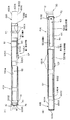
図1は実施例のバッテリー2の斜視図、図2(A)はバッテリー2の平面図、(B)は(A)のB矢視図、(C)は(A)のC矢視図、(D)は(A)のD矢視図、図3(E)は図2(D)のE矢視図、(F)は(E)のF矢視図である。
図4(A)はバッテリー2を前方から見た正面図、(B)は(A)のB矢視図、(C)は(A)のC矢視図である。
図5はバッテリー2を前方斜め上方から見た斜視図、図6はバッテリー2の上下を反転し斜め上方から見た斜視図である。
図7はバッテリー2の断面図である。
図8は上ケース12の斜視図、図9は下ケース14の斜視図である。
図10はバッテリー2のコネクタ部分の断面図である。
なお、添付図面中、円筒面や曲面、傾斜面を表すために、部材や部分の表面に複数の直線や曲線を描いた図面も存在している。
It will now be described with reference to the drawings with the embodiments of the present invention.
1 is a perspective view of the
4A is a front view of the
FIG. 5 is a perspective view of the
FIG. 7 is a cross-sectional view of the
FIG. 8 is a perspective view of the
FIG. 10 is a cross-sectional view of the connector portion of the
In the accompanying drawings, there are also drawings in which a plurality of straight lines and curves are drawn on the surfaces of members and portions in order to represent cylindrical surfaces, curved surfaces, and inclined surfaces.
図1〜図6に示すように、バッテリー2は、例えば電子機器のバッテリー収容室に装脱可能に装着されるものであり、2つの電池セル40を収容するケース10と、ケース10から露出するコネクタ30と、電池セル40をケース10内で保持する保持体50と、導電板60と、プリント基板70とを備えている。
ケース10は、厚さ方向の両端に位置する上面10Cおよび下面10Dと、前記厚さよりも大きい寸法の幅方向の両端に位置する左右の側面10Eと、前記幅よりも大きい寸法の前後方向の両端に位置する前面10Aおよび後面10Bとを有する扁平な矩形板状に形成されている。なお、説明の便宜上、ケース10の左右方向はケース10の前方から見た状態でいうものとする。
2つの側面10Eには、幅方向外方に突出しつつ長さ方向に延在する係合壁1002が設けられ、係合壁1002は、側面10Eの厚さ方向の中心部に対して上面10Cまたは下面10D寄りの各側面10E箇所に設けられ、本実施例では、上面10C寄りの箇所に設けられている。
係合壁1002の延在方向の中間部には抜け止め用の切り欠き1004が形成され、本実施例では切り欠き1004は、係合壁1002の前面10A寄りの箇所に形成されている。
係合壁1002は、バッテリー2のバッテリー収容室への挿入時に、バッテリー収容室に設けられた係合溝(不図示)に係合し、バッテリー収容室においてバッテリー2の厚さ方向の位置決めがなされる。
また、バッテリー収容室にバッテリー2が挿入されコネクタ30と電子機器側コネクタ部とが接触した状態で、バッテリー収容室に設けられた抜け止め用凸部(不図示)が切り欠き1004に係脱可能に係合し、バッテリー2の装着状態が安定される。
また、2つの側面10Eの後面10B寄りの箇所にストッパ壁1006が膨出形成されている。このストッパ壁1006は係合壁1002に接続され、バッテリーの後面10Bを電子機器のバッテリー収容室に挿入できないようにしたものであり、いわゆる逆挿防止用の壁である。
As shown in FIGS. 1 to 6, the
The
The two
A
The
Further, in a state where the
Further, a
本実施例では、図7、図8、図9に示すように、ケース10は上ケース12と下ケース14との2つのケースが溶着によって結合されることで構成されている。
本実施例では、上面10Cは上ケース12の上面1202で構成され、下面10Dは下ケース14の下面1402で構成され、前面10Aは上ケース12および下ケース14の前面1204、1404で構成され、後面10Bは上ケース12および下ケース14の後面1206、1406で構成され、側面10Eは上ケース12および下ケース14の側面1208、1408で形成されている。
また、係合壁1002は上ケース12の側面に形成され、ストッパ壁1006は下ケース14の側面に形成されている。
また、本実施例では、図7に示すように、上ケース12の上面1202の内面の周囲の複数箇所と、下ケース14の下面1402の内面の周囲の複数箇所にそれぞれ凸部15が膨出形成され、これら凸部15によりケース10内で電池セル40を保持するようにしている。
また、本実施例では、図7に示すように、上ケース12の上面1202には、長さ方向の全長にわたり幅方向の中央部分が幅方向の両側寄り部分よりも上方に偏位した偏位部1210が形成され、また、下ケース14の下面1402には、長さ方向の全長にわたり幅方向の中央部分が幅方向の両側寄り部分よりも上方に偏位した偏位部1211が形成されている。これら偏位部1210、1211の内面とケース10の内部に収容された電池セル40の上面4002、下面4004との間には、充電時に電池セル40が膨張した際にこの膨張を吸収するための隙間1212、1213が形成されている。
In this embodiment, as shown in FIGS. 7, 8, and 9, the
In the present embodiment, the
The
Further, in the present embodiment, as shown in FIG. 7, the
Further, in this embodiment, as shown in FIG. 7, the
図1〜図7に示すように、コネクタ30は、ケース10の前面10Aに前方に突出して設けられ、本実施例ではコネクタ30は、前面10Aの幅方向の右側の端部寄りの箇所に幅方向に延在するように設けられている。
前面10Aの厚さ方向におけるコネクタ30の位置は、左右の側面10Eの係合壁1002が上面10Cまたは下面10Dに臨む面を基準として決定されており、本実施例では、コネクタ30の厚さ方向における位置の基準となる面は、係合壁1002が下面10Dに臨む面1002Aである。
図4、図10に示すように、コネクタ30は、前面10Aから長さ方向に膨出されたコ字状のコネクタ壁部32の内側に設けられ、コネクタ30は、コネクタ壁部32の内側に配置された端子構成用部材36と、電池セル40に接続された接片部33とを有している。
コネクタ壁部32はコネクタ30を補強するもので、コネクタ壁部32は、幅方向に間隔をおき厚さ方向に延在する一対の縦壁3202と、上面10C寄りの箇所で幅方向に延在し一対の縦壁3202の厚さ方向の端部間を接続する横壁3204を有している。
一対の縦壁3202と横壁3204により長さ方向に(前方に)開放状でかつ厚さ方向の両端の面のうちの他方の面に(下方に)開放状の空間3206が形成されている。
図5、図10に示すように、端子構成用部材36は、合成樹脂などの絶縁材料から形成され、開放状の空間3206に配置されている。
端子構成用部材36は、幅方向に間隔をおき長さ方向に(前方に)開放状で厚さ方向に延在する複数の溝3602を有し、複数の溝3602は、下面10Dに開放状に形成されている。
接片部33は、前方および下方に開放された状態で前記幅方向に対向する一対の接片34が前記幅方向に間隔をおいて複数並べられて構成され、本実施例では、複数の接片34は、一対の縦壁3202の間に幅方向に間隔をおいて設けられ、本実施例では、幅方向において互いに対向する各溝3602の側面を構成するように配置されている。
本実施例では、コネクタ30の下面3022とケース10の下面10Dは同一面上に位置している。
As shown in FIGS. 1 to 7, the
The position of the
As shown in FIGS. 4 and 10, the
The
A pair of
As shown in FIGS. 5 and 10, the
The
The
In the present embodiment, the
次にバッテリー2の内部について説明する。
図11、図12はケース10を取り除いた電池セル40部分の斜視図、図13はケース10を取り除いた電池セル40部分の底面図、図14はケース10を取り除いた電池セル40部分の平面図、図15(A)は図13のA矢視図、(B)は図13のB矢視図、図16(A)は図14のA矢視図、(B)は図14のB矢視図である。
図17、図18、図19は電池セル40が保持体50に保持された状態を示す斜視図である。
図20は電池セル40、保持体50、導電板60の分解斜視図である。
図21(A)、(B)はプリント基板70の斜視図である。
図22は保持体50の斜視図である。
図23、図24は導電板の斜視図、図25は導電板60と電池セル40の溶接部分を示す斜視図、図26(A)、(B)は電池セル40の斜視図である。
Next, the inside of the
11 and 12 are perspective views of the
17, 18, and 19 are perspective views showing a state in which the
FIG. 20 is an exploded perspective view of the
21A and 21B are perspective views of the printed
FIG. 22 is a perspective view of the holding
23 and 24 are perspective views of the conductive plate, FIG. 25 is a perspective view showing a welded portion between the
まず、図26を参照して電池セル40から説明すると、電池セル40は本実施例ではリチウムイオン電池あるいはニッケル水素電池などの充電可能な電池セルで構成されている。
電池セル40は、導電性金属材料からなり、厚さ方向の両端に位置する矩形状の上面4002および下面4004と、上面4002と下面4004とを接続する4つの側面4006とを有する扁平な矩形板状の外装缶42を有している。本実施例では外装缶42は鋼材にニッケルメッキが施された材料で構成されている。
電池セル40の正極端子44は、4つの側面4006のうちの1つの側面4006に外装缶42と絶縁した状態で突出形成されている。より詳細には、断面が矩形状の非導電材料からなる膨出部が側面4006から突出形成されこの膨出部の先端面が正極端子44とされている。また、正極端子44が設けられた箇所の残りの外装缶42箇所が電池セル40の負極端子46として形成されている。
First, the
The
The
図17、図18、図19、図22に示すように、保持体50は2つの電池セル40を平面視長方形に並べた状態で収容する第1電池収容部50Aと第2電池収容部50Bとを備えている。
保持体50は、非導電性で弾性を有する材料からなり、前記平面視長方形の短辺に対応し前記第1電池収容部50Aに収容される電池セル40の外装缶42の側面4006に当て付けられる本発明の第4の側片である第1側片51と、平面視長方形の一方の長辺に対応する電池セル40の外装缶42の側面4006に当て付けられる本発明の第1の側片である第2側片52と、平面視長方形の他方の長辺に対応する電池セル40の外装缶42の側面4006に当て付けられる本発明の第2の側片である第3側片53と、2つの電池セル40の向かい合う外装缶42の側面4006間に配置される本発明の第1の側片である第4側片54と、4つの側片51、52、53、54の縁から突出し電池セル40の外装缶42の上面4002または下面4004の一方の面(本実施例では下面4004)の縁寄りの箇所に当て付けられる縁片56とを有している。
本実施例では、2つの電池セル40は、図17、図18に示すように、第1電池収容室50Aに収容された電池セル40の正極端子44が第2側片52に臨み、第2電池収容室50Bに収容された電池セル40の正極端子44が第3側片53に臨むように第1、第2電池収容室50A、50Bに収容されている。
なお、説明の便宜上、第1電池収容室50Aに収容された電池セル40を第1電池セル40Aといい、第2電池収容室50Bに収容された電池セル40を第2電池セル40Bという。
As shown in FIGS. 17, 18, 19, and 22, the holding
The holding
In the present embodiment, as shown in FIGS. 17 and 18, the two
For convenience of explanation, the
図20、図22に示すように、第1側片51は、第1電池セル40Aの外装缶42の1つの側面4006の全長にわたるように延在形成されている。
図17、図20に示すように、第1側片51の表面には、プリント基板70を取着するためのリブ5102が膨出形成され、このリブ5102を介してプリント基板70が取着され、プリント基板70は第1側片51に沿って延在している。
図20、図21に示すように、プリント基板70にはコネクタ30が実装されており、プリント基板70には、図10に示すコネクタ30の正極用の接片34、負極用(グランド用)の接片34、中点用の接片34にそれぞれ導通する正極用の導通部72、負極用の導通部74、中点用の導通部76が形成されている。
また、プリント基板70には、図21に示すように、制御回路を構成するLSIや電子部品が実装されており、前記制御回路は、コネクタ30のデータ通信用の接片34を介して電子機器側の制御部との間でバッテリー2の特性や識別情報などのデータを送受信したり、各導通部72、74、76を介して各電池セル40の出力電圧や出力電流などを監視する機能を有している。
As shown in FIGS. 20 and 22, the
As shown in FIGS. 17 and 20,
As shown in FIGS. 20 and 21, the
Further, as shown in FIG. 21, LSIs and electronic components constituting a control circuit are mounted on the printed
図18、図22に示すように、第2側片52は、その一端が第1側片51に連結されており、第1電池セル40Aの外装缶42の側面4006の全長にわたって延在し、かつ、第2電池セル40Bの第4側片54寄りの側面4006まで延在するように形成され、第2側片52の先端寄り箇所は第4側片54の端部に連結されている。
第2側片52には該第2側片52の延在方向に間隔をおいて導電板60(図20)を係合させるための第2係合凹部5202と第3係合凹部5204が形成されている。
また、第1側片51寄りの第2係合凹部5202には、第1電池セル40Aの正極端子44を突出させるための開口5206が形成されている。なお、開口5206は、正極端子44が嵌め込まれる大きさで形成されている。
As shown in FIGS. 18 and 22, the
The
In addition, an
図17、図22に示すように、第3側片53は、第1側片51と切り離されて形成され、第1、第2電池セル40A、40Bの外装缶42の側面4006にわたって延在するように延在し、中間部が第4側片54の端部に連結されている。
なお、第2側片52と第3側片53は、電池セル40の正極端子44を含んだ側面4006と、この側面4006に対向する側面4006間の寸法に対応した距離をおいて配置され、第1、第2電池収容部50A、50Bにそれぞれ電池セル40が挿入されることでそれら電池セル40の外装缶42の側面4006に第2側片52と第3側片53とが当て付けられるように構成されている。
第4側片54から離れた第3側片53部分には、第2電池セル40Bの正極端子44を突出させるための開口5302が形成されている。なお、開口5302は、正極端子44が嵌め込まれる大きさで形成されている。
また、第3側片53には導電板60を係合させるための第1係合凹部5304が形成されている。
As shown in FIGS. 17 and 22, the
The
An
The
図19、図22に示すように、第4側片54は、第1側片51とともに電池セル40の正極端子44を含まない2つの側面4006に当て付けられるように構成されている。
第4側片54は、第1側片51と同様に電池セル40の全長にわたって延在形成されている。
As shown in FIGS. 19 and 22, the
The
図17、図20に示すように、縁片56は、4つの側片51、52、53、54の縁から突出し第1、第2電池セル40A、40Bの下面4004の縁寄りの箇所に当て付けられる幅で形成されている。
第4側片54の縁から突出する縁片56には、その延在方向の中間部に開口5604が形成されている。
さらに、第4側片54の延在方向の中間部には、図22に示すように、2つの電池セル40の上面4002の互いに隣合う縁にそれぞれ当て付けられる縁片57が形成されている。
なお、縁片56は、図20に示すように、第1電池セル40Aの下面4004においては、その4辺にわたって延在するように矩形枠状に形成されている。したがって、第1電池セル40Aの下面4004は、4つの縁片56の中央の開口5602からその4つの縁部を除いた部分が露出する。また、第2電池セル40Bの下面4004は、第3側片53の縁片56および第4側片54の縁片56以外の箇所が露出する。
すなわち、図17に示すように、第1、第2電池セル40A、40Bが保持体50に収容された状態で、第1、第2電池セル40A、40Bの上面4002は縁片57が当て付けられる箇所を除いた全ての部分が開放されており、また、下面4004は縁片56が存在するもののそれらの中央部分を露出させる切り欠きが形成されていることになり、充電時に電池セル40が膨張した際にこの膨張を許容するように構成されている。
また、第1、第2電池セル40A、40Bは、縁片56が形成されていない保持体50の箇所から第1、第2電池収容室50A、50Bに対して装脱される。
As shown in FIGS. 17 and 20, the
The
Furthermore, as shown in FIG. 22,
In addition, as shown in FIG. 20 , the
That is, as shown in FIG. 17, with the first and
The first and
導電板60は、図20に示すように、電気的に直列に接続した2つの電池セル40の正極端子44とコネクタ30とを接続する正極端子接続用薄板60Aと、電気的に直列に接続した2つの電池セル40の負極端子46とコネクタ30とを接続する負極端子接続用薄板60Bとで構成されている。
正極端子接続用薄板60Aおよび負極端子接続用薄板60Bは共に導電材料で形成されている。
正極端子接続用薄板60Aは、第3側片53が位置する側に配置される第1薄板61および第2薄板62と、第2側片52が位置する側に配置される第3薄板63で構成されている。
より詳細には、正極端子接続用薄板60Aは、図20、図23、図24に示すように、第2電池セル40Bの正極端子44に接続される第1薄板61と、この第1薄板61に取着され第1電池セル40Aの負極端子46に接続される第2薄板62と、第1電池セル40Aの正極端子44に接合されるとともにプリント基板70の導電部72に接続される第3薄板63で構成されている。
第1薄板61は、第4側片54に接続する縁片56上を通り第3側片53に接続される縁片56上を延在する延在部6102と、延在部6102の一端から屈曲され第2電池セル40Bの正極端子44に接合可能な2つの正極端子接合用屈曲部6104と、延在部6102の中間部から第2薄板62上に屈曲される2つの薄板接合用屈曲部6106と、延在部6102の他端から屈曲されプリント基板70の中点用の導電部76に接続される導電部接合用屈曲部6108とを有している。
第1薄板61の2つの正極端子接合用屈曲部6104のうちの1つは第2電池セル40Bの正極端子44に溶接により接合されている。
正極端子接合用屈曲部6104と薄板接合用屈曲部6106をそれぞれ2つ設けた理由は、組み立て時に一方の屈曲部のみを使用し、電池セル40を交換した際に、上述の一方の屈曲部を切り離し、残りの他方の屈曲部を使用できるようにしたものである。
第1薄板61の導電部接合用屈曲部6108は、溶接によりプリント基板70の中点用の導電部76に接合されている。これにより本実施例では、正極端子接続用薄板60Aの一部を利用し、2つの電池セル40の互いに接続された正極端子44と負極端子46の接続部分の電位をプリント基板70の導電部76に供給し、プリント基板70の前記制御回路によって2つの電池セル40の出力電圧や出力電流を監視するようにしている。
As shown in FIG. 20 , the
Both the positive terminal connecting
The positive terminal connecting
More specifically, as shown in FIGS. 20, 23, and 24 , the positive terminal connecting
The first
One of the two positive terminal joining
The reason why the two
The
第2薄板62は、図20に示すように、その一部が第3側片53が存在しない箇所で第1電池セル40Aの側面4006上をその全長にわたって延在するとともに、残りの部分が第3側片53上に延在し第3側片53の第1係合凹部5304上に係合されて配置されている。
第2薄板62は、図24に示すように、2枚の金属製の薄板6202と、それら2枚の薄板6202の間に介在されたサーミスタ6204とで構成されている。本実施例ではサーミスタ6204はPTC(Positive Temperature Coefficient)サーミスタで構成されている。PTCサーミスタは、温度上昇に伴い抵抗値が増加する正特性を有するものであり、過大電流が流れると抵抗値が急激に増大して流れる電流を抑制することで電池セル40およびバッテリー2が装着された電子機器を保護する機能を有している。
そして、図20に示すように、2枚の金属製の薄板6202とサーミスタ6204とが重ね合わされた厚さの大きな部分は、第3側片53が存在しない第1電池セル40Aの側面4006上を延在し、第1側片51寄りに位置する第2薄板62の端部は、第1電池セル40Aの側面4006に溶接により接合され、すなわち第1電池セル40Aの負極端子46に接合されている。
また、第3側片53の第1係合凹部5304に延在する第2薄板62部分は、一枚の薄板6202のみにより構成され、この第2薄板62部分は第1係合凹部5304に係合されている。
前記2つの薄板接合用屈曲部6106は、第1係合凹部5304に係合された第2薄板62部分の上に重ね合わされ、その一方が溶接により第2薄板62に接合されている。
本実施例では、第2薄板62が第1係合凹部5304に係合された状態で、正極端子接続用薄板60Aを構成する第1薄板61および第2薄板62の位置決めがなされるように、すなわち、第3側片53が当て付けられた外装缶42の側面4006に対して直交する方向の位置決めがなされるように構成され、これにより第1薄板61および第2薄板62の組み付けを簡単に行えるようにしている。
また、本実施例では、第2薄板62が第1係合凹部5304に係合されその上に2つの薄板接合用屈曲部6106が重ね合わされた状態で、それら薄板接合用屈曲部6106の表面は、第1係合凹部5304が形成された箇所以外の第3側片53の表面と同一面上に位置するか、あるいは、第3側片53の表面よりも低い箇所に位置するように形成され、これにより保持体50で保持され導電板60が組みつけられた電池セル40のユニットの小型化を図るようにしている。
As shown in FIG. 20 , the second
As shown in FIG. 24 , the second
Then, as shown in FIG. 20, the thick portion where the two metal
Further, the second
The two thin plate joining
In the present embodiment, the first
Further, in this embodiment, the surface of the thin plate bonding
図12に示すように、第3薄板63は、第2側片52の第2係合凹部5202上でその全長にわたって延在し開口5206を覆うように配置された延在部6302と、延在部6302の一端から屈曲されプリント基板70の正極用の導電部72に接続される導電部接合用屈曲部6304とを有している。
開口5202上において延在部6302はその延在方向の端部寄りの箇所が第1電池セル40Aの正極端子44の端部寄りの箇所(第1側片51から離れた側の正極端子44の端部寄りの箇所)に溶接により接合されている。このように延在部6302を正極端子44の端部寄りの箇所に接合する理由は、電池セル40を交換した際に、その接合された部分を切り離し、延在部6302の新たな端部を正極端子44の他方の端部寄りの箇所に接合できるようにしたものである。
本実施例では、第3薄板63が第2係合凹部5202に係合された状態で、第3薄板63の位置決めがなされるように、すなわち、第2側片52が当て付けられた外装缶42の側面4006に対して直交する方向の第3薄板63の位置決めがなされるように構成されている。
また、本実施例では、第3薄板63が第2係合凹部5202に係合された状態で、その第3薄板63の表面は、第2係合凹部5202が形成された箇所以外の第2側片52の表面と同一面上に位置するか、あるいは、第2側片52の表面よりも低い箇所に位置するように形成されている。
導電部接合用屈曲部6304は、プリント基板70の正極用の導電部72に溶接により接合されている。
これにより正極端子接続用薄板60Aによって、第2電池セル40Bの正極端子44と、第1電池セル40Aの負極端子46と、第1電池セル40Aの正極端子44と、コネクタ30とが接続されることになる。
As shown in FIG. 12, the third
On the
In the present embodiment, the outer can in which the third
In this embodiment, the third
The
Thus, the
図12、図20に示すように、負極端子接続用薄板60Bは、第2側片52が位置する側に配置される第4薄板64および第5薄板65で構成されている。
より詳細には、負極端子接続用薄板60Bは、第2電池セル40Bの負極端子46に接続される第4薄板64と、この第4薄板64に取着されプリント基板70の導電部74に接続される第5薄板65で構成されている。
第4薄板64は、その一部が第2電池セル40Bの側面4006上でその全長にわたって延在するとともに、残りの部分が第2側片52上に延在し第2側片52の第3係合凹部5204上に係合されて配置されている。
第4薄板64は、第2薄板62と同様に、図23に示すように、2枚の金属製の薄板6402と、それら2枚の薄板6402の間に介在されたサーミスタ6404とで構成されている。本実施例ではサーミスタ6404は前述のサーミスタ6204と同様のPTCサーミスタで構成されている。
そして、図12に示すように、2枚の金属製の薄板6402とサーミスタ6404とが重ね合わされた厚さの大きな部分は、第2側片52が存在しない第2電池セル40Bの側面4006上を延在し、第1側片51から離れた側に位置する第4薄板64の端部は、第2電池セル40Bの側面4006に溶接により接合され、すなわち第2電池セル40Bの負極端子46に接合されている。
また、第2側片52の第3係合凹部5204に延在する第4薄板64部分は、一枚の薄板6402のみにより構成され、この第4薄板64部分は第3係合凹部5204に係合されている。
As shown in FIGS. 12 and 20, the negative electrode terminal connecting
More specifically, the negative electrode terminal connecting thin plate 60B is connected to the fourth
A portion of the fourth
Similarly to the second
Then, as shown in FIG. 12, the thick portion where the two metal
In addition, the fourth
第5薄板65は、図12に示すように、第4側片54に接続する縁片56上を通り第2側片52に接続される縁片56上を延在する延在部6502と、延在部6502の一端から屈曲され第4薄板54に接合可能な2つの薄板接合用屈曲部6504と、延在部6502の他端から屈曲されプリント基板70の導電部74に接続される導電部接合用屈曲部6506とを有している。
第5薄板65の2つの薄板接合用屈曲部6504のうちの1つは、第3係合凹部5204上に位置する第4薄板64部分に溶接により接合されている。
薄板接合用屈曲部6504を2つ設けた理由は、組み立て時に一方の屈曲部のみを使用し、電池セル40を交換した際に、上述の一方の屈曲部を切り離し、残りの他方の屈曲部を使用できるようにしたものである。
第5薄板65の導電部接合用屈曲部6506は、図12、図20に示すように、溶接によりプリント基板70の導電部74に接合されている。
本実施例では、第4薄板64が第3係合凹部5204に係合された状態で、負極端子接続用薄板60Bを構成する第4薄板64および第5薄板65の位置決めがなされるように、すなわち、第2側片52が当て付けられた外装缶42の側面4006に対して直交する方向の位置決めがなされるように構成され、これにより第4薄板64および第5薄板65の組み付けを簡単に行えるようにしている。
また、本実施例では、第4薄板64が第3係合凹部5204に係合されその上に2つの薄板接合用屈曲部6504が重ね合わされた状態で、それら薄板接合用屈曲部6504の表面は、第3係合凹部5204が形成された箇所以外の第2側片52の表面と同一面上に位置するか、あるいは、第2側片52の表面よりも低い箇所に位置するように形成され、これにより保持体50で保持され導電板60が組みつけられた電池セル40のユニットの小型化を図るようにしている。
As shown in FIG. 12 , the fifth
One of the two thin plate joining
The reason for providing two thin plate joining
As shown in FIGS. 12 and 20 , the
In the present embodiment, the fourth
Further, in this embodiment, the surface of the thin plate bonding
本実施例のバッテリー2によれば、保持体50によって2つの電池セル40を絶縁しつつ保持し、かつ、保持体50によって導電板60を電池セル40から絶縁しつつ保持体50に沿わせて配置するので、従来のように絶縁紙や両面接着テープを用いて電池セル間の絶縁、電池セル同士の固定、電池セルと導電板との絶縁を行う場合に比べてバッテリー2の小型化を図れ、部品点数を大幅に削減できるとともに、組み立てを簡素化することができ、コスト低減を図る上で有利となる。
また、バッテリー2の組み立て時、第1乃至第3係合凹部5304、5202、5204を利用して導電板60を保持体50に位置決めしつつ簡単に配置できる。したがって、電池セル40を保持体50に保持させた状態で、例えば、治具などを用いてプリント基板70を第1側片51の前部に位置決めして配置すれば、導電板60は第1乃至第3係合凹部5304、5202、5204を利用して保持体50に位置決めして配置され、したがって、プリント基板70および導電板60を位置決めした状態で溶接を簡単に行うことができ、組み立ての簡素化を図る上で有利となる。
また、第1、第2電池収容室50A、50Bにおいて、各電池セル40はそれらの上面4002および下面4004の周辺箇所を除く部分が開放されているので、電池セル40が充電時などに上面4002および下面4004の中央部分が膨張して厚みが増えてもその厚みを吸収でき、また、この膨張した上面4002および下面4004の中央部分に保持体50が存在していないので、ケース10の内面と電池セル40との間の隙間1212、1213を有効に利用でき、バッテリー2のケース10が厚さ方向に膨張することを防止する上で有利となる。
また、第2電池セル40Bの正極端子44と第1電池セル40Aの負極端子46とを接続する正極端子接続用薄板60Aを、第4側片54に接続する縁片56箇所を通る第1薄板61を含んで構成し、かつ、第2電池セル40Bの負極端子46とプリント基板70の導電部74とを接続する負極端子接続用薄板60Bを、第4側片54に接続する縁片56箇所を通る第1薄板61、第5薄板65を含んで構成したので、例えば、バッテリー2がポケットに入れられその厚さ方向に変形されても各正極端子接続用薄板60A、負極端子接続用薄板60Bの接合部へ掛かる外力を減少でき、接続不良などを防止する上で有利となる。
According to the
Further, when the
Further, in each of the first and second
Further, the first thin plate passing through the 56 edge portions connecting the positive terminal connecting
なお、上述の実施例では、2つの電池セル40が収容されたバッテリーについて説明したが、本発明は単一の電池セルを収容するバッテリーにも無論適用可能であり、その場合にはバッテリーは次のように構成される。
バッテリーは、扁平な矩形板状の電池セルを収容するケースと、前記ケースから露出するコネクタと、前記電池セルを前記ケース内で保持する保持体と、前記電池セルの正極端子と負極端子とをそれぞれ前記コネクタに接続する導電板とを備えている。
前記電池セルは導電性金属材料からなり、厚さ方向の両端に位置する矩形状の上面および下面と、前記上面と下面とを接続する4つの側面とを有する扁平な矩形板状の外装缶を有している。
前記電池セルの正極端子は、前記4つの側面のうちの1つに前記外装缶と絶縁した状態で形成され、前記正極端子が設けられた箇所の残りの前記外装缶箇所が前記電池セルの負極端子として形成されている。
前記保持体は電池セルを収容する電池収容部を備えている。
前記保持体は、非導電性で弾性を有する材料からなり、前記電池収容部に収容される電池セルの外装缶の少なくとも3つの側面に当て付けられる第1乃至第3側片と、前記3つの側片の縁から突出し前記電池セルの外装缶の上面または下面の一方の面の縁寄りの箇所に当て付けられる縁片とを有している。
前記導電板は、前記保持体上を延在し前記電池収容部に収容される電池セルの正極端子と前記コネクタとを接続する導電性で弾性を有する正極端子接続用薄板と、前記保持体上を延在し前記電池セルの負極端子と前記コネクタとを接続する導電性で弾性を有する負極端子接続用薄板とで構成されている。
前記正極端子接続用薄板は前記正極端子と前記コネクタとに溶接により接合されると共に、前記負極端子接続用薄板は前記負極端子と前記コネクタとに溶接により接合されている。
そして、第1乃至第3係合凹部5304、5202、5204や第1乃至第5薄板61〜65などの実施例の構成が適宜採用される。
また、実施例では、2つの電池セルを電気的に直列に接続した場合について説明したが、本発明は、2つの電池セルを電気的に並列に接続した場合にも無論適用される。
In the above-described embodiment, the battery in which the two
Battery, a case for accommodating a flat rectangular plate of the battery cell, a connector exposed from the case, a holding member for holding the battery cell in said case, positive and negative terminals of the pre-Symbol batteries cell Are respectively connected to the connector.
The battery cell is made of a conductive metal material, and includes a flat rectangular plate-shaped outer can having rectangular upper and lower surfaces positioned at both ends in the thickness direction and four side surfaces connecting the upper and lower surfaces. Have.
The positive terminal of the battery cell is formed in one of the four side surfaces in an insulated state from the outer can, and the remaining portion of the outer can where the positive terminal is provided is the negative electrode of the battery cell. It is formed as a terminal.
The holding body includes a battery housing portion that houses the battery cell.
The holding body is made of a non-conductive and elastic material, and includes first to third side pieces applied to at least three side surfaces of an outer can of a battery cell accommodated in the battery accommodating portion, and the three And an edge piece that protrudes from the edge of the side piece and is applied to a location near the edge of one surface of the upper surface or the lower surface of the outer can of the battery cell.
The conductive plate is a conductive and elastic thin plate for positive electrode terminal connection that connects the positive terminal of the battery cell that extends over the holder and is accommodated in the battery accommodating portion, and the connector; And a conductive and elastic thin plate for connecting a negative electrode terminal and connecting the negative electrode terminal of the battery cell and the connector.
The positive terminal connecting thin plate is joined to the positive terminal and the connector by welding, and the negative terminal connecting thin plate is joined to the negative terminal and the connector by welding.
And the structure of Example, such as the 1st thru | or 3rd engaging recessed
Moreover, although the Example demonstrated the case where two battery cells were electrically connected in series, this invention is naturally applicable also when two battery cells are electrically connected in parallel.
2……バッテリー、10……ケース、30……コネクタ、40……電池セル、42……外装缶、44……正極端子、46……負極端子、50……保持体、51……第1側片、52……第2側片、53……第3側片、54……第4側片、56……縁片、60……導電板、60A……正極端子接続用薄板、60B……負極端子接続用薄板。
2 ... Battery, 10 ... Case, 30 ... Connector, 40 ... Battery cell, 42 ... Exterior can, 44 ... Positive electrode terminal, 46 ... Negative electrode terminal, 50 ... Holder, 51 ...
Claims (19)
前記電池セルを少なくとも2つ収容するケースと、
前記ケースから露出するコネクタと、
非導電性の材料からなり前記ケース内で2つの前記電池セルを平面視長方形に並べた状態で収容する第1電池収容部及び第2電池収容部を有する保持体と、
前記保持体上を延在し前記第1電池収容部と前記第2電池収容部にそれぞれ収容される2つの前記電池セルと前記コネクタとを電気的に接続する導電性を有する導電板と、を備え、
前記保持体は、
前記平面視長方形の2つの長辺に対応し前記第1電池収容部と第2電池収容部にそれぞれ収容される前記電池セルの側面に当て付けられる第1の側片及び第2の側片と、
前記第1の側片及び前記第2の側片を接続し、且つ前記第1電池収容部と第2電池収容部に収容される2つの前記電池セルの向かい合う側面間に配置される第3の側片と、を有し、
前記導電板は、前記第1の側片及び前記第2の側片に沿って配置される
ことを特徴とするバッテリー。 A flat rectangular plate-shaped battery cell having a rectangular upper surface and a lower surface located at both ends in the thickness direction, and four side surfaces connecting the upper surface and the lower surface ;
A case containing at least two of the battery cells ;
A connector exposed from the case;
A holding member having a first battery accommodating section and a second battery accommodating section for accommodating the two said cells in the case of a non-conductive material in a state arranged in a rectangular shape as viewed in plan,
A conductive plate extending on the holding body and electrically connecting the two battery cells and the connector respectively accommodated in the first battery accommodating portion and the second battery accommodating portion; Prepared,
The holder is
A first side piece and a second side piece applied to the side surfaces of the battery cells corresponding to the two long sides of the rectangular shape in plan view and housed in the first battery housing portion and the second battery housing portion, respectively; ,
A third side that connects the first side piece and the second side piece and is disposed between the opposite side surfaces of the two battery cells housed in the first battery housing portion and the second battery housing portion. Side pieces, and
The battery according to claim 1, wherein the conductive plate is disposed along the first side piece and the second side piece .
前記第1の側片、前記第2の側片、前記第3の側片及び前記第4の側片の縁から突出し前記第1電池収容部と前記第2電池収容部にそれぞれ収容される前記電池セルの外装缶の上面または下面の一方の面の縁寄りの箇所に当て付けられる縁片と、をさらに有する
ことを特徴とする請求項1記載のバッテリー。 The holding member includes a fourth side piece which is abutted to the side surface of the battery cell accommodated in said first battery accommodating section corresponding to the short side of the rectangular shape as viewed in plan,
Wherein the first side piece and the second side piece, the third said accommodated respectively from the edge of the side piece and the fourth side piece to the second battery accommodating section and projecting the first battery accommodating portion of the The battery according to claim 1, further comprising: an edge piece applied to a position near the edge of one of the upper surface and the lower surface of the outer can of the battery cell.
前記第1の側片と前記第3の側片には、前記正極端子接続用薄板または前記負極端子接続用薄板の一部が係合され位置決めされる係合凹部が形成され、
前記正極端子接続用薄板および前記負極端子接続用薄板は、それぞれそれらの一部が前記係合凹部に係合されて前記第1の側片または前記第2の側片上に配置されていることを特徴とする請求項3記載のバッテリー。 The positive terminal connecting thin plate and the negative terminal connecting thin plate are disposed over a part of the first side piece or the second side piece ,
Wherein the first side piece and the third side piece, the engaging recess portion of the positive terminal connecting thin plate or said negative terminal connecting thin plate is positioned engaged is formed,
The positive terminal connecting thin plate and said negative terminal connecting thin plate, that some of them respectively is disposed in said engaging recess to be engaged the first side piece and the second side piece on The battery according to claim 3 .
前記第1の側片と前記第2の側片には、前記正極端子接続用薄板または前記負極端子接続用薄板の一部が係合され位置決めされる係合凹部が形成され、
前記正極端子接続用薄板および前記負極端子接続用薄板は、それぞれそれらの一部が前記係合凹部に係合されて前記第1の側片または前記第2の側片上に配置され、
前記正極端子接続用薄板および前記負極端子接続用薄板は、それらの一部が前記係合凹部に係合することで、前記側片が当て付けられた前記電池セルの側面に対して直交する方向の位置決めがなさることを特徴とする請求項3記載のバッテリー。 The positive terminal connecting thin plate and the negative terminal connecting thin plate are arranged to extend over a part of the first side piece or the second side piece ,
Wherein the first of the the side piece second side piece, the engaging recess portion of the positive terminal connecting thin plate or said negative terminal connecting thin plate is positioned engaged is formed,
The positive terminal connecting thin plate and said negative terminal connecting thin plate is a part of their respective disposed in the engagement recess engaged by said first side piece and the second side piece on,
The positive terminal connecting thin plate and said negative terminal connecting thin plate, by a part thereof is engaged with the engaging recess, a direction perpendicular to the side surface of the battery cell in which the side piece was abutted The battery according to claim 3 , wherein the positioning is performed.
前記第1の側片と前記第2の側片には、前記正極端子接続用薄板または前記負極端子接続用薄板の一部が係合され位置決めされる係合凹部が形成され、
前記正極端子接続用薄板および前記負極端子接続用薄板は、それぞれそれらの一部が前記係合凹部に係合されて前記第1の側片または前記第2の側片上に配置され、
前記正極端子接続用薄板および前記負極端子接続用薄板が、それぞれそれらの一部が前記係合凹部に係合された状態で、前記係合凹部に係合された前記正極端子接続用薄板または前記負極端子接続用薄板の表面は、前記係合凹部が形成された箇所以外の前記第1の側片または前記第2の側片の表面と同一面上に位置するか、あるいは、前記第1の側片または前記第2の側片の表面よりも低い箇所に位置するように形成されていることを特徴とする請求項3記載のバッテリー。 The positive terminal connecting thin plate and the negative terminal connecting thin plate are arranged to extend over a part of the first side piece or the second side piece,
Wherein the first of the the side piece second side piece, the engaging recess portion of the positive terminal connecting thin plate or said negative terminal connecting thin plate is positioned engaged is formed,
The positive terminal connecting thin plate and said negative terminal connecting thin plate is a part of their respective disposed in the engagement recess engaged by said first side piece and the second side piece on,
The positive terminal connecting thin plate and said negative terminal connecting thin plate is in a state in which a part thereof is engaged with the engaging recesses, respectively, the engaging recesses engaged the positive terminal connecting thin plate or said the surface of the negative terminal connecting thin plate, or positioned in the engagement the non locations if recesses are formed a first side piece and the second side piece of the same surface on, or the first 4. The battery according to claim 3 , wherein the battery is formed so as to be located at a position lower than a surface of the side piece or the second side piece .
前記第1の側片及び前記第2の側片には、前記正極端子が挿入される開口が形成され、
前記正極端子接続用薄板は、前記第2の側片または縁片上を延在しその一端が前記第2電池収容部に収容される電池セルの前記開口から露出する前記正極端子に接合されると共にその他端が前記第1電池収容部に収容される電池セルの前記負極端子に接合される薄板と、前記第1の側片または前記縁片上を延在しその一端が前記第1電池収容部に収容される電池セルの前記負極端子に接合されると共にその他端が前記コネクタに接合される薄板により構成されていることを特徴とする請求項3記載のバッテリー。 The electronic cell housed in the first battery housing portion has the positive terminal facing the first side piece , and the electronic cell housed in the second battery housing portion has the positive electrode on the second side piece. It is housed so that the terminal faces,
Wherein the first side piece and the second side piece, opening the positive electrode terminal is inserted is formed,
The positive electrode terminal connecting thin plate extends on the second side piece or the edge piece, and one end thereof is joined to the positive electrode terminal exposed from the opening of the battery cell accommodated in the second battery accommodating portion. a thin plate other end is joined to the negative terminal of the battery cell accommodated in said first battery accommodating section, wherein the first side piece or one end extends a piece the edge in the first battery accommodating section 4. The battery according to claim 3 , wherein the battery is constituted by a thin plate joined to the negative electrode terminal of the battery cell to be accommodated and the other end joined to the connector.
前記第1電池収容部に収容される電子セルは、前記第1の側片に前記正極端子が臨み、かつ、前記第2電池収容部に収容される電子セルは、前記第2の側片に前記正極端子が臨むように収容され、
前記第1の側片及び前記第2の側片には、前記正極端子が挿入される開口が形成され、
前記正極端子接続用薄板には、前記開口から臨む正極端子に接触可能な2つの接合部がそれら第2、第2の側片の延在方向に間隔をおいて2つ設けられ、それら2つの接合部のうちの一方の接合部が前記正極端子に接合されていることを特徴とする請求項3記載のバッテリー。 Said first side piece and the second side piece extends along the side of the outer can of the battery cell,
Electronic cell accommodated in said first battery accommodating section, wherein the positive terminal faces to the first side piece and electronic cell accommodated in said second battery accommodating section, the second side piece It is accommodated so that the positive electrode terminal faces,
Wherein the first side piece and the second side piece, opening the positive electrode terminal is inserted is formed,
Wherein the positive terminal connecting thin plate, two junctions capable of contacting the positive electrode pin facing from the opening thereof second, provided two at intervals in the extending direction of the second side piece, these two The battery according to claim 3, wherein one of the two joints is joined to the positive terminal.
前記負極端子接続用薄板は、前記保持体上を通り前記第2電池収容部に収容される電池セルの負極端子と前記コネクタとを接続するように配置され、
前記正極端子接続用薄板と前記負極端子接続用薄板が電池セルの負極端子に接続される部分は、それぞれ前記第1の側片及び前記第2の側片が存在しない前記電池セルの側面部分であり、
前記正極端子接続用薄板と前記負極端子接続用薄板が電池セルの負極端子に接続される部分は、2枚の薄板の間にサーミスタが挟まれて構成されていることを特徴とする請求項3記載のバッテリー。 The thin plate for positive electrode terminal connection passes over the holding body, the positive electrode terminal of the battery cell accommodated in the second battery accommodating portion, the negative electrode terminal of the battery cell accommodated in the first battery accommodating portion, and the first battery. It is arranged to connect the positive electrode terminal accommodated in the accommodating portion and the connector,
The negative electrode terminal connection thin plate is disposed so as to connect the connector and the negative electrode terminal of the battery cell that is housed in the second battery housing portion through the holder.
The portions where the positive terminal connecting thin plate and the negative terminal connecting thin plate are connected to the negative terminal of the battery cell are side portions of the battery cell where the first side piece and the second side piece do not exist, respectively. Yes,
Said portion of said positive terminal connecting thin plate negative terminal connecting thin plate are connected to the negative terminal of the battery cell, according to claim 3, characterized in that the thermistor is configured sandwiched between two thin plates The battery described.
前記負極端子接続用薄板は、前記保持体上を通り前記第2電池収容部に収容される電池セルの負極端子と前記コネクタとを接続するように配置され、
前記正極端子接続用薄板のうち前記第2電池収容部に収容される電池セルの正極端子と前記第1電池収容部に収容される電池セルの負極端子を接続する部分は、前記第3の側片に接続する縁片上を延在する薄板を含んで構成され、
前記負極端子接続用薄板は、前記第3の側片に接続する縁片上を延在する薄板を含んで構成されていることを特徴とする請求項3記載のバッテリー。 The thin plate for positive electrode terminal connection passes over the holding body, the positive electrode terminal of the battery cell accommodated in the second battery accommodating portion, the negative electrode terminal of the battery cell accommodated in the first battery accommodating portion, and the first battery. It is arranged to connect the positive electrode terminal accommodated in the accommodating portion and the connector,
The negative electrode terminal connection thin plate is disposed so as to connect the connector and the negative electrode terminal of the battery cell that is housed in the second battery housing portion through the holder.
The portion connecting the positive electrode terminal of the battery cell housed in the second battery housing portion and the negative electrode terminal of the battery cell housed in the first battery housing portion of the thin plate for connecting the positive electrode terminal is the third side. Comprising a thin plate extending over the edge piece connecting to the piece ,
4. The battery according to claim 3 , wherein the negative terminal connecting thin plate includes a thin plate extending on an edge piece connected to the third side piece .
前記電池セルは、前記縁片が設けられていない前記側片の箇所から前記第1電池収容部及び前記第2電池収容部に挿入されることを特徴とする請求項1〜15のいずれかに記載のバッテリー。 The edge piece is provided so as to extend only on one surface of the upper surface or the lower surface of the electronic cell housed in the first battery housing portion and the second battery housing portion,
The said battery cell is inserted in a said 1st battery accommodating part and a said 2nd battery accommodating part from the location of the said side piece in which the said edge piece is not provided , The any one of Claims 1-15 characterized by the above-mentioned . The battery described.
さらに、前記第3の側片には、前記第1電池収容部及び前記第2電池収容部に収容される電子セルの上面または下面の他方の面上を延在する縁片が設けられていることを特徴とする請求項1〜15のいずれかに記載のバッテリー。 Each of the edge pieces is provided so as to extend only on one surface of the upper surface or the lower surface of the electronic cell housed in the first battery housing portion and the second battery housing portion,
Further, the third side piece is provided with an edge piece extending on the other surface of the upper surface or the lower surface of the electronic cell accommodated in the first battery accommodating portion and the second battery accommodating portion. The battery according to any one of claims 1 to 15 .
前記保持体には、前記第1電池収容部及び前記第2電池収容部に収容される電子セルの前記縁片に当接する上面または下面の一方の面の縁を除いた残りの中央部分を露出させる切り欠きが設けられていることを特徴とする請求項1〜18のいずれかに記載のバッテリー。 The edge piece is provided so as to extend only on one surface of the upper surface or the lower surface of the electronic cell housed in the first battery housing portion and the second battery housing portion,
In the holding body, the remaining central portion excluding the edge of one surface of the upper surface or the lower surface that contacts the edge piece of the electronic cell housed in the first battery housing portion and the second battery housing portion is exposed. The battery according to any one of claims 1 to 18, wherein a notch is provided.
Priority Applications (10)
| Application Number | Priority Date | Filing Date | Title |
|---|---|---|---|
| JP2004368849A JP4706251B2 (en) | 2004-12-21 | 2004-12-21 | battery |
| KR1020077013978A KR20070086461A (en) | 2004-12-21 | 2005-11-04 | Battery case |
| ES05806073T ES2349651T3 (en) | 2004-12-21 | 2005-11-04 | BATTERY BOX. |
| EP05806073A EP1831941B1 (en) | 2004-12-21 | 2005-11-04 | Battery case |
| US11/722,417 US8039142B2 (en) | 2004-12-21 | 2005-11-04 | Battery case |
| PCT/JP2005/020682 WO2006067918A2 (en) | 2004-12-21 | 2005-11-04 | Battery case |
| DK05806073.2T DK1831941T3 (en) | 2004-12-21 | 2005-11-04 | Battery box |
| CNB2005800441018A CN100499209C (en) | 2004-12-21 | 2005-11-04 | Battery |
| DE602005022766T DE602005022766D1 (en) | 2004-12-21 | 2005-11-04 | BATTERY CASE |
| TW094139732A TWI307189B (en) | 2004-12-21 | 2005-11-11 | Battery |
Applications Claiming Priority (1)
| Application Number | Priority Date | Filing Date | Title |
|---|---|---|---|
| JP2004368849A JP4706251B2 (en) | 2004-12-21 | 2004-12-21 | battery |
Publications (3)
| Publication Number | Publication Date |
|---|---|
| JP2006179212A JP2006179212A (en) | 2006-07-06 |
| JP2006179212A5 JP2006179212A5 (en) | 2007-01-25 |
| JP4706251B2 true JP4706251B2 (en) | 2011-06-22 |
Family
ID=35909253
Family Applications (1)
| Application Number | Title | Priority Date | Filing Date |
|---|---|---|---|
| JP2004368849A Expired - Fee Related JP4706251B2 (en) | 2004-12-21 | 2004-12-21 | battery |
Country Status (10)
| Country | Link |
|---|---|
| US (1) | US8039142B2 (en) |
| EP (1) | EP1831941B1 (en) |
| JP (1) | JP4706251B2 (en) |
| KR (1) | KR20070086461A (en) |
| CN (1) | CN100499209C (en) |
| DE (1) | DE602005022766D1 (en) |
| DK (1) | DK1831941T3 (en) |
| ES (1) | ES2349651T3 (en) |
| TW (1) | TWI307189B (en) |
| WO (1) | WO2006067918A2 (en) |
Families Citing this family (18)
| Publication number | Priority date | Publication date | Assignee | Title |
|---|---|---|---|---|
| JP4123517B2 (en) | 2003-12-26 | 2008-07-23 | ソニー株式会社 | Battery device |
| KR100770106B1 (en) * | 2006-10-24 | 2007-10-24 | 삼성에스디아이 주식회사 | Lithium secondary battery |
| KR100984133B1 (en) * | 2008-04-11 | 2010-09-28 | 삼성에스디아이 주식회사 | Battery pack |
| KR101042750B1 (en) | 2009-01-09 | 2011-06-20 | 삼성에스디아이 주식회사 | Battery Pack |
| JP5536382B2 (en) | 2009-07-08 | 2014-07-02 | 矢崎総業株式会社 | Power supply |
| DE102009035499A1 (en) * | 2009-07-31 | 2011-02-03 | Daimler Ag | Single cell for a battery |
| JP5457098B2 (en) * | 2009-08-03 | 2014-04-02 | 日立マクセル株式会社 | Battery pack and manufacturing method thereof |
| KR101166024B1 (en) * | 2010-08-04 | 2012-07-19 | 삼성에스디아이 주식회사 | External terminal assembly and battery pack using the same |
| KR101234240B1 (en) * | 2011-02-11 | 2013-02-18 | 삼성에스디아이 주식회사 | Battery pack having partition wall between core pack and protection circuit module |
| US20130089755A1 (en) * | 2011-10-11 | 2013-04-11 | In-Soo Park | Battery Pack |
| DE102013010001A1 (en) * | 2013-06-14 | 2014-12-18 | Leopold Kostal Gmbh & Co. Kg | Stationary storage battery and energy storage module |
| US9893329B2 (en) * | 2014-07-04 | 2018-02-13 | Makita Corporation | Electronic power supply device |
| KR101794266B1 (en) | 2016-01-07 | 2017-11-07 | 삼성에스디아이 주식회사 | Tray for battery module adapted for slide assembly |
| JP2020030883A (en) * | 2016-12-15 | 2020-02-27 | ヤマハ発動機株式会社 | Assembled battery |
| CN110311084B (en) * | 2018-03-20 | 2024-08-02 | 东莞新能德科技有限公司 | Battery cell structure and electronic product |
| KR102779228B1 (en) * | 2019-07-08 | 2025-03-11 | 삼성에스디아이 주식회사 | Insulation tape and feeding device for insulation tape |
| JP7331538B2 (en) * | 2019-08-01 | 2023-08-23 | セイコーエプソン株式会社 | mobile device |
| CN115347204A (en) * | 2021-05-14 | 2022-11-15 | 中创新航科技股份有限公司 | Battery manufacturing method and battery |
Citations (7)
| Publication number | Priority date | Publication date | Assignee | Title |
|---|---|---|---|---|
| JPS56109457A (en) * | 1980-01-31 | 1981-08-29 | Sanyo Electric Co Ltd | Flat battery |
| US4431717A (en) * | 1981-01-31 | 1984-02-14 | Sony Corporation | Battery case |
| JP2003086158A (en) * | 2001-09-14 | 2003-03-20 | Sony Corp | Battery pack |
| JP2003086155A (en) * | 2001-09-14 | 2003-03-20 | Sony Corp | Battery pack |
| JP2003123731A (en) * | 2001-08-06 | 2003-04-25 | Matsushita Electric Ind Co Ltd | Rectangular sealed battery |
| US20030215702A1 (en) * | 2002-05-08 | 2003-11-20 | Yuuji Tanjou | Secondary cell module and method of its production |
| EP1422770A1 (en) * | 2001-08-06 | 2004-05-26 | Matsushita Electric Industrial Co., Ltd. | Angular enclosed battery |
Family Cites Families (2)
| Publication number | Priority date | Publication date | Assignee | Title |
|---|---|---|---|---|
| JP2001266826A (en) | 2000-03-17 | 2001-09-28 | Sony Corp | Electronic apparatus |
| US6840328B2 (en) * | 2002-07-11 | 2005-01-11 | Schlumberger Technology Corporation | Anti-extrusion apparatus and method |
-
2004
- 2004-12-21 JP JP2004368849A patent/JP4706251B2/en not_active Expired - Fee Related
-
2005
- 2005-11-04 US US11/722,417 patent/US8039142B2/en not_active Expired - Fee Related
- 2005-11-04 WO PCT/JP2005/020682 patent/WO2006067918A2/en active Application Filing
- 2005-11-04 DE DE602005022766T patent/DE602005022766D1/en active Active
- 2005-11-04 CN CNB2005800441018A patent/CN100499209C/en not_active Expired - Fee Related
- 2005-11-04 DK DK05806073.2T patent/DK1831941T3/en active
- 2005-11-04 KR KR1020077013978A patent/KR20070086461A/en not_active Application Discontinuation
- 2005-11-04 EP EP05806073A patent/EP1831941B1/en not_active Not-in-force
- 2005-11-04 ES ES05806073T patent/ES2349651T3/en active Active
- 2005-11-11 TW TW094139732A patent/TWI307189B/en not_active IP Right Cessation
Patent Citations (8)
| Publication number | Priority date | Publication date | Assignee | Title |
|---|---|---|---|---|
| JPS56109457A (en) * | 1980-01-31 | 1981-08-29 | Sanyo Electric Co Ltd | Flat battery |
| US4431717A (en) * | 1981-01-31 | 1984-02-14 | Sony Corporation | Battery case |
| JP2003123731A (en) * | 2001-08-06 | 2003-04-25 | Matsushita Electric Ind Co Ltd | Rectangular sealed battery |
| EP1422770A1 (en) * | 2001-08-06 | 2004-05-26 | Matsushita Electric Industrial Co., Ltd. | Angular enclosed battery |
| JP2003086158A (en) * | 2001-09-14 | 2003-03-20 | Sony Corp | Battery pack |
| JP2003086155A (en) * | 2001-09-14 | 2003-03-20 | Sony Corp | Battery pack |
| US20040070366A1 (en) * | 2001-09-14 | 2004-04-15 | Toshio Takeshita | Battery pack |
| US20030215702A1 (en) * | 2002-05-08 | 2003-11-20 | Yuuji Tanjou | Secondary cell module and method of its production |
Also Published As
| Publication number | Publication date |
|---|---|
| WO2006067918A3 (en) | 2007-02-15 |
| DE602005022766D1 (en) | 2010-09-16 |
| EP1831941B1 (en) | 2010-08-04 |
| EP1831941A2 (en) | 2007-09-12 |
| ES2349651T3 (en) | 2011-01-07 |
| DK1831941T3 (en) | 2010-11-01 |
| KR20070086461A (en) | 2007-08-27 |
| CN101084593A (en) | 2007-12-05 |
| US8039142B2 (en) | 2011-10-18 |
| US20100003585A1 (en) | 2010-01-07 |
| CN100499209C (en) | 2009-06-10 |
| WO2006067918A2 (en) | 2006-06-29 |
| JP2006179212A (en) | 2006-07-06 |
| TWI307189B (en) | 2009-03-01 |
| TW200638578A (en) | 2006-11-01 |
Similar Documents
| Publication | Publication Date | Title |
|---|---|---|
| JP4706251B2 (en) | battery | |
| EP2693516B1 (en) | Battery pack | |
| JP5138379B2 (en) | Secondary battery module terminal connection member | |
| JP4800323B2 (en) | Sensing board assembly for secondary battery module | |
| KR101297186B1 (en) | Secondary Battery Pack | |
| JP5154451B2 (en) | Battery module | |
| EP2337106B1 (en) | Rechargeable battery | |
| CN101573807B (en) | Battery pack of excellent productability and structural stability | |
| JP2008520076A5 (en) | ||
| JP2007172893A (en) | Battery module | |
| JP2008524797A (en) | Method for manufacturing secondary battery module | |
| JP2013161692A (en) | Power storage element, power storage element group | |
| KR20170062976A (en) | Battery pack | |
| JP2005100689A (en) | Battery pack | |
| JP4622502B2 (en) | battery | |
| KR20070080868A (en) | PCM with fastening structure and battery pack including the same | |
| JP2003223876A (en) | Battery pack | |
| JP2007200630A (en) | Battery pack, its assembling method, and portable electronic appliance using it | |
| JP4318517B2 (en) | Battery pack | |
| JP3806696B2 (en) | Pack battery | |
| KR20220065605A (en) | Battery Pack, Electric Device, Vehicle, and Battery Management System | |
| CN222507799U (en) | Battery cover plate, battery and battery pack | |
| JP2005285680A (en) | Battery pack and battery pack assembling method | |
| JP2020047502A (en) | Manufacturing apparatus of power storage device and manufacturing method of power storage device | |
| WO2016204011A1 (en) | Battery |
Legal Events
| Date | Code | Title | Description |
|---|---|---|---|
| A521 | Request for written amendment filed |
Free format text: JAPANESE INTERMEDIATE CODE: A523 Effective date: 20061108 |
|
| A621 | Written request for application examination |
Free format text: JAPANESE INTERMEDIATE CODE: A621 Effective date: 20061108 |
|
| A521 | Request for written amendment filed |
Free format text: JAPANESE INTERMEDIATE CODE: A523 Effective date: 20061201 |
|
| RD02 | Notification of acceptance of power of attorney |
Free format text: JAPANESE INTERMEDIATE CODE: A7422 Effective date: 20090817 |
|
| RD04 | Notification of resignation of power of attorney |
Free format text: JAPANESE INTERMEDIATE CODE: A7424 Effective date: 20091013 |
|
| A131 | Notification of reasons for refusal |
Free format text: JAPANESE INTERMEDIATE CODE: A131 Effective date: 20100803 |
|
| A521 | Request for written amendment filed |
Free format text: JAPANESE INTERMEDIATE CODE: A523 Effective date: 20100927 |
|
| A01 | Written decision to grant a patent or to grant a registration (utility model) |
Free format text: JAPANESE INTERMEDIATE CODE: A01 Effective date: 20110215 |
|
| A61 | First payment of annual fees (during grant procedure) |
Free format text: JAPANESE INTERMEDIATE CODE: A61 Effective date: 20110228 |
|
| R250 | Receipt of annual fees |
Free format text: JAPANESE INTERMEDIATE CODE: R250 |
|
| LAPS | Cancellation because of no payment of annual fees |