JP4703553B2 - Wheelchair access device with stackable platform - Google Patents
Wheelchair access device with stackable platform Download PDFInfo
- Publication number
- JP4703553B2 JP4703553B2 JP2006502916A JP2006502916A JP4703553B2 JP 4703553 B2 JP4703553 B2 JP 4703553B2 JP 2006502916 A JP2006502916 A JP 2006502916A JP 2006502916 A JP2006502916 A JP 2006502916A JP 4703553 B2 JP4703553 B2 JP 4703553B2
- Authority
- JP
- Japan
- Prior art keywords
- platform
- platform portion
- actuator
- wheelchair lift
- vehicle
- Prior art date
- Legal status (The legal status is an assumption and is not a legal conclusion. Google has not performed a legal analysis and makes no representation as to the accuracy of the status listed.)
- Expired - Fee Related
Links
- 238000012546 transfer Methods 0.000 claims description 20
- 230000007246 mechanism Effects 0.000 claims description 15
- 230000004044 response Effects 0.000 claims description 4
- 238000005096 rolling process Methods 0.000 description 26
- 230000004888 barrier function Effects 0.000 description 20
- 238000011161 development Methods 0.000 description 8
- 238000010586 diagram Methods 0.000 description 4
- 230000009471 action Effects 0.000 description 2
- 230000000903 blocking effect Effects 0.000 description 2
- 239000007787 solid Substances 0.000 description 2
- XAGFODPZIPBFFR-UHFFFAOYSA-N aluminium Chemical compound [Al] XAGFODPZIPBFFR-UHFFFAOYSA-N 0.000 description 1
- 229910052782 aluminium Inorganic materials 0.000 description 1
- 230000000712 assembly Effects 0.000 description 1
- 238000000429 assembly Methods 0.000 description 1
- 239000011248 coating agent Substances 0.000 description 1
- 238000000576 coating method Methods 0.000 description 1
- 238000013461 design Methods 0.000 description 1
- 230000009977 dual effect Effects 0.000 description 1
- 230000005484 gravity Effects 0.000 description 1
- 230000009191 jumping Effects 0.000 description 1
- 238000000034 method Methods 0.000 description 1
- 238000012986 modification Methods 0.000 description 1
- 230000004048 modification Effects 0.000 description 1
- 230000037081 physical activity Effects 0.000 description 1
- 239000000843 powder Substances 0.000 description 1
- 230000000452 restraining effect Effects 0.000 description 1
- 230000007480 spreading Effects 0.000 description 1
Images


Classifications
-
- A—HUMAN NECESSITIES
- A61—MEDICAL OR VETERINARY SCIENCE; HYGIENE
- A61G—TRANSPORT, PERSONAL CONVEYANCES, OR ACCOMMODATION SPECIALLY ADAPTED FOR PATIENTS OR DISABLED PERSONS; OPERATING TABLES OR CHAIRS; CHAIRS FOR DENTISTRY; FUNERAL DEVICES
- A61G3/00—Ambulance aspects of vehicles; Vehicles with special provisions for transporting patients or disabled persons, or their personal conveyances, e.g. for facilitating access of, or for loading, wheelchairs
- A61G3/02—Loading or unloading personal conveyances; Facilitating access of patients or disabled persons to, or exit from, vehicles
- A61G3/06—Transfer using ramps, lifts or the like
- A61G3/062—Transfer using ramps, lifts or the like using lifts connected to the vehicle
-
- Y—GENERAL TAGGING OF NEW TECHNOLOGICAL DEVELOPMENTS; GENERAL TAGGING OF CROSS-SECTIONAL TECHNOLOGIES SPANNING OVER SEVERAL SECTIONS OF THE IPC; TECHNICAL SUBJECTS COVERED BY FORMER USPC CROSS-REFERENCE ART COLLECTIONS [XRACs] AND DIGESTS
- Y10—TECHNICAL SUBJECTS COVERED BY FORMER USPC
- Y10S—TECHNICAL SUBJECTS COVERED BY FORMER USPC CROSS-REFERENCE ART COLLECTIONS [XRACs] AND DIGESTS
- Y10S414/00—Material or article handling
- Y10S414/134—Handicapped person handling
Landscapes
- Health & Medical Sciences (AREA)
- Public Health (AREA)
- Life Sciences & Earth Sciences (AREA)
- Animal Behavior & Ethology (AREA)
- General Health & Medical Sciences (AREA)
- Veterinary Medicine (AREA)
- Vehicle Step Arrangements And Article Storage (AREA)
- Handcart (AREA)
Description
本出願は、2003年1月29日出願の米国特許出願第10/353,544号に基づく優先権を主張する。
本発明は、プラットフォームを用いた車椅子アクセス装置に関し、更に詳細には、本装置を展開及び格納するフロアを備える車両と共に使用される重ね式プラットフォーム部分を有する、車内からの視界を遮らない車椅子リフトプラットフォーム構造体に関する。
This application claims priority from US patent application Ser. No. 10 / 353,544, filed Jan. 29, 2003.
The present invention relates to a wheelchair access device using a platform, and more particularly, a wheelchair lift platform that has an overlaid platform portion for use with a vehicle that includes a floor for deploying and storing the device and that does not obstruct visibility from within the vehicle. Concerning the structure.
リフト及び傾斜部などの身障者用車椅子車両アクセス装置は、車両に装着され、且つ車両に対して展開/格納することができる。車椅子利用者は通常、リフト又は傾斜部プラットフォームに沿って車椅子を移動させ、機械式、電動式、空気圧式、又は油圧式などで動作可能なリフト機構及びプラットフォーム構造体を利用して、車椅子を地面から車両へ、及び、車両から地面へ移動させる。既知の車椅子昇降プラットフォーム構造体は、車両自体内に格納されるべきプラットフォーム構造体として固体剛体パネル又はフロアを含む。従って、車椅子アクセス装置は、車両のフロアスペースの一部と共に使用され、更に通路を遮り、車両内の利用可能なスペースを制限する可能性がある。 Wheelchair vehicle access devices for disabled persons, such as lifts and ramps, are mounted on the vehicle and can be deployed / stored in the vehicle. Wheelchair users typically move the wheelchair along a lift or ramp platform and use a lift mechanism and platform structure that can be operated mechanically, electrically, pneumatically, hydraulically, etc. To the vehicle and from the vehicle to the ground. Known wheelchair lifting platform structures include solid rigid panels or floors as platform structures to be stored within the vehicle itself. Thus, the wheelchair access device may be used with a portion of the vehicle floor space, further blocking the passageway and limiting the available space within the vehicle.
身体障害者にとっては、電動式プラットフォーム構造体の運動のほとんど又は全てを与えるように動力が供給される車椅子アクセス装置を利用可能であることにより、移動性が増すことになる。車椅子の乗員の身体活動は不自由であることから、これは特に有用なものである。このようなリフトは通常、プラットフォーム構造体の昇降用に枢動機構を有し、例えば、1993年11月16日に発行の「二重油圧平行四辺形アーム式車椅子リフト」でGoodrichに付与された米国特許第5,261,779号、及び2001年5月29日に出願人の譲受人に発行された「車椅子リフト用二重機能車内バリア/ブリッジプレート組立体」でDepuy他に付与された米国特許第6,238,169号を参照されたい。これらの各々は、通常は商用車用の二重油圧平行四辺形アーム式車椅子リフト組立体を開示している。リフト組立体は、平行四辺形リンク機構に接続されたプラットフォームを有する。上記組立体の両方においては、リフトのプラットフォームが格納位置にあるときに、プラットフォームが本質的に出入口を塞ぎ、出入口又は車両ドアの窓を極めて使いにくくする。更に、車両のフロアに固定されている車椅子アクセス装置自体が、車内のスペース及び車両内からの視界を制限する可能性がある。 For disabled persons, the availability of wheelchair access devices that are powered to provide most or all of the movement of the motorized platform structure will increase mobility. This is particularly useful because the physical activity of wheelchair occupants is inconvenient. Such lifts typically have a pivoting mechanism for raising and lowering the platform structure and were granted to Goodrich, for example, “Double Hydraulic Parallelogram Arm Wheelchair Lift” issued November 16, 1993. United States Patent No. 5,261,779, and United States granted to Depuy et al. In "Double Function Car Barrier / Bridge Plate Assembly for Wheelchair Lift" issued to assignee of the applicant on May 29, 2001 See Patent No. 6,238,169. Each of these discloses a double hydraulic parallelogram arm wheelchair lift assembly, typically for commercial vehicles. The lift assembly has a platform connected to a parallelogram linkage. In both of the above assemblies, when the lift platform is in the retracted position, the platform essentially plugs the doorway, making the doorway or vehicle door window extremely difficult to use. Furthermore, the wheelchair access device itself fixed to the vehicle floor may limit the space in the vehicle and the field of view from within the vehicle.
格納位置においてドアを完全には塞がない別の車椅子リフトが記載されており、例えば、1987年5月12日に発行の「回転式車椅子リフト」でブラウン他に付与された米国特許第4,664,584号は、垂直に伸縮するスライド管と、該スライド管の下端部に取付けられ、プラットフォームをスライド管に平行に車両から出し入れできる水平車椅子プラットフォーム支持アームとを有する回転油圧式リフトを開示している。しかしながら、回転式車椅子リフトに用いられているプラットフォーム構造体及び枢動機構は、かなりのスペース量を必要とする。 Another wheelchair lift is described that does not completely block the door in the retracted position, for example, U.S. Pat. No. 4, granted to Brown et al. In "Rotating Wheelchair Lift" issued May 12, 1987. No. 664,584 discloses a rotary hydraulic lift having a vertically extending slide tube and a horizontal wheelchair platform support arm attached to the lower end of the slide tube and capable of moving the platform in and out of the vehicle parallel to the slide tube. ing. However, the platform structure and pivot mechanism used in the rotary wheelchair lift requires a significant amount of space.
従来技術で公知の装置は、リフト及びプラットフォーム構造体の設計に関して安全性、安定性、及び操作の簡便性を提供する点で部分的に成功しているに過ぎない。折り畳み可能な複数部分からなるプラットフォーム構造体が、使用していないときのプラットフォーム区域を削減することは知られている。内側及び外側プラットフォーム部分間にヒンジを用いて、外側部分が内側部分の外側で内側部分と接して上昇して折り畳むようにするプラットフォーム構造体の既知の例として、2002年4月30日に発行の「折り畳み可能なプラットフォームを備える車椅子リフト」でKamedaに付与された米国特許第6,379,102号がある。しかしながら、折り畳まれているか、或いは展開されている最中の動作であるかの予測が欠如していることは、プラットフォーム構造体を格納位置から展開する際におけるこのタイプのプラットフォーム組立体の大きな欠点である。例えば格納位置において外側のプラットフォーム部分は、適切に固定されていない限り垂下しており種々の位置を取る可能性がある。車椅子の乗員又は操縦者が、リフト構造体構成要素と干渉するのを防ぐための転がりストップが備えられていなかったか、又は有効ではなかったかのいずれかである。更に、露出された剛体リンク機構が、操縦者又は乗員と接触する可能性もある。このようなリンク機構は、煩わしく外見上良くないことに加え、リフト操作中にこれらのリンク機構と接触する乗員或いは操縦者を実質的に危険にさらす可能性もある。 Devices known in the prior art are only partially successful in providing safety, stability, and ease of operation with respect to lift and platform structure design. It is known that a foldable platform structure reduces the platform area when not in use. As a known example of a platform structure that uses a hinge between the inner and outer platform portions to allow the outer portion to rise and fold against the inner portion outside the inner portion, published on April 30, 2002 There is US Pat. No. 6,379,102 issued to Kameda for “Wheelchair Lift with Foldable Platform”. However, the lack of prediction of whether the action is being folded or unfolded is a major disadvantage of this type of platform assembly when deploying the platform structure from the storage position. is there. For example, in the retracted position, the outer platform portion may hang down and assume various positions unless properly secured. Either the wheelchair occupant or the operator was not provided with a rolling stop to prevent interference with the lift structure components, or was not effective. In addition, the exposed rigid linkage may come into contact with the operator or occupant. In addition to being cumbersome and unattractive, such linkages can also substantially endanger occupants or pilots who come into contact with these linkages during a lift operation.
更に、ケーブル装置が幾つかの他の欠点を有し、中でも、ケーブルが適切な長さに調節することが困難であり、ケーブルの伸長及び温度により伸縮する傾向により頻繁に再調整する必要がある。更に、使用中に擦り切れ又は破断する可能性があり、強度に限界がある。多くの既知のリフト装置はまた、リフト動作中に揺動、回転、ジャンプ、又は拘束の傾向があり、更なる危険性が生じる可能性がある。 In addition, the cable system has several other disadvantages, among which the cable is difficult to adjust to the proper length and needs to be readjusted more frequently due to cable stretching and the tendency to stretch with temperature. . Furthermore, there is a possibility of fraying or breaking during use, and the strength is limited. Many known lifting devices are also prone to rocking, rotating, jumping, or restraining during the lifting operation, which can create additional risks.
障害を有するか、或いは可動性が制限されている乗員についての増大する懸念事項に対処するためには、リフトプラットフォーム構造体を格納すると同時にドア及び特に車両からの視界を遮らないドア窓へのアクセスの向上を可能にするために、車両のフロアを占有するスペースを最小限に抑える小型で格納可能な車椅子アクセス装置を提供することが望ましいことになる。 To address the growing concern for occupants with obstacles or limited mobility, access to door windows that store the lift platform structure and at the same time do not obstruct the view from the vehicle, especially the vehicle. It would be desirable to provide a small, retractable wheelchair access device that minimizes the space occupying the vehicle floor.
本発明は、車両内の格納スペースが制限された車両のフロアからの展開を容易にすると同時に、車両内からの乗員の視界を遮らない車椅子アクセス装置に関する。後で説明する実施形態では、車椅子アクセス装置は、展開時に延長プラットフォームフロアを形成する少なくとも2つのプラットフォーム部分を含むプラットフォーム構造体を備えた平行四辺形リフトを利用する。プラットフォーム部分は、固定プラットフォーム部分と可動プラットフォーム部分とを含み、これらは、格納配置において格納のために重ねることができ、低い上下方向輪郭により、車内からの視界を遮らないようにすることができる。 The present invention relates to a wheelchair access device that facilitates deployment from the floor of a vehicle in which a storage space in the vehicle is limited, and at the same time does not block an occupant's view from inside the vehicle. In embodiments described below, the wheelchair access device utilizes a parallelogram lift with a platform structure that includes at least two platform portions that form an extended platform floor when deployed. The platform portion includes a fixed platform portion and a movable platform portion that can be stacked for storage in a storage configuration, and the low vertical profile can ensure that the view from within the vehicle is not obstructed.
車椅子アクセス装置のプラットフォーム構造体は、1対の延長支持体を展開させ、この延長支持体の第1部分に固定プラットフォーム部分を有すると同時に、1対の延長支持体の第1部分から第2部分へ展開可能な可動プラットフォームを備え、展開時に可動プラットフォーム部分が並んだ固定プラットフォーム部分を備えたプラットフォームフロアを形成する。アクチュエータに動力を供給してリフトの垂直アームを移動させ、これにより延長支持体を枢動させて、格納配置と展開配置の間で可動プラットフォーム部分を移動させる。これに応じて、格納配置では、低い上下方向輪郭のために固定プラットフォーム部分と可動プラットフォーム部分が重ねられる。加えて、固定プラットフォーム部分と可動プラットフォーム部分が重なった格納配置にある車椅子アクセス装置の水平方向輪郭は、車両内の格納スペースを最小化すると同時に、現在利用されている従来の車椅子リフト装置よりも扱い易い構造体を提供する。従って、本発明は、車両内の格納スペースを増大させることなく、更に又車両の窓又はドアを通じての視界を遮ることなく展開時に延長したプラットフォームを提供することができる。一方が可動であり且つ他方が固定である少なくとも2つのプラットフォーム部分を用いることにより、プラットフォーム構造体は自動的に重なり、所定位置に格納されて、車両の開口部近くにある実質的に上下方向の配置で高さの低い輪郭を形成することができる。この目的のため、重なったプラットフォーム構造体の上下方向の高さは、車椅子リフトが展開配置にある時の折り畳まれていないプラットフォーム構造体の水平方向長さの約半分とすることができる。 The platform structure of the wheelchair access device deploys a pair of extension supports and has a fixed platform portion on a first portion of the extension support and at the same time a first portion to a second portion of the pair of extension supports. A platform floor is formed which includes a movable platform that can be expanded to a fixed platform portion that is aligned with the movable platform portion when deployed. Power is applied to the actuator to move the vertical arm of the lift, thereby pivoting the extension support to move the movable platform portion between the retracted and deployed configurations. Correspondingly, in the retracted arrangement, the fixed platform portion and the movable platform portion are overlapped for a low vertical profile. In addition, the horizontal profile of the wheelchair access device in the storage arrangement with the fixed platform part and the movable platform part overlapping minimizes the storage space in the vehicle and at the same time handles more than conventional wheelchair lift devices currently in use. Provide an easy structure. Thus, the present invention can provide a platform that is extended during deployment without increasing the storage space in the vehicle and without obstructing the view through the vehicle window or door. By using at least two platform portions, one movable and the other fixed, the platform structure automatically overlaps and is stored in place so that it is substantially vertically positioned near the vehicle opening. A low profile can be formed by arrangement. For this purpose, the vertical height of the overlapping platform structures may be about half of the horizontal length of the unfolded platform structure when the wheelchair lift is in the deployed configuration.
簡潔に要約すると、本発明は、フロアを有する車両と共に使用するための重ね式プラットフォームを備えた車椅子アクセス装置に関し、車椅子アクセス装置は、右側垂直アームと、第1及び第2部分を有する延長支持体とを含む。延長支持体の第1部分は、垂直アームに枢動可能に結合されている。垂直アームは、プラットフォーム構造体を展開するよう動作する。左側もまた、垂直アームと、第1及び第2部分を有する延長支持体とを有し、この第1部分が垂直アームに結合されている。右側及び左側延長支持体の第1部分の間に取付けられた固定プラットフォーム部分と、右側及び左側垂直アームを車両の車外位置と車内位置との間で動かすために動力を供給可能なアクチュエータがある。有利には、本装置は、右側及び左側延長支持体の間に結合された可動プラットフォーム部分を含み、右側及び左側延長支持体の第1部分と第2部分との間で移動する。リンク機構は、可動プラットフォーム部分に接続されており、可動プラットフォーム部分が右側及び左側延長支持体の第1部分で固定プラットフォーム部分と共に格納される格納配置と、可動プラットフォーム部分が右側及び左側延長支持体の第2部分に移動された展開配置との間で、アクチュエータにより移動する。 Briefly summarized, the present invention relates to a wheelchair access device with a stackable platform for use with a vehicle having a floor, the wheelchair access device having a right vertical arm and an extended support having first and second portions. Including. The first portion of the extension support is pivotally coupled to the vertical arm. The vertical arm operates to deploy the platform structure. The left side also has a vertical arm and an extended support having first and second portions, the first portion being coupled to the vertical arm. There is a fixed platform portion mounted between the first portion of the right and left extension supports and an actuator that can be powered to move the right and left vertical arms between an out-of-vehicle position and an in-vehicle position of the vehicle. Advantageously, the apparatus includes a movable platform portion coupled between the right and left extension supports and moves between the first and second portions of the right and left extension supports. The linkage is connected to the movable platform portion, wherein the movable platform portion is stored with the fixed platform portion at the first portion of the right and left extension supports, and the movable platform portion of the right and left extension supports. It moves with an actuator between the deployment arrangement moved to the 2nd part.
本発明に特有のものと考えられる新規の特徴は、添付の請求項で説明されている。しかしながら、本発明自体、並びに好ましい利用形態、更にその目的及び利点は、添付図面と共に以下の実施形態の詳細な説明を参照することによって最も良く理解される。 The novel features believed characteristic of the invention are set forth in the appended claims. However, the invention itself, as well as preferred uses, as well as objects and advantages thereof, are best understood by referring to the following detailed description of the embodiments in conjunction with the accompanying drawings.
図面、とりわけ図1及び図2を参照すると、車両12と関連して使用される車椅子アクセス装置10が示されている。車両12はフロア14を有し、フロア14の上に車椅子アクセス装置10が取付けられ、重ね式プラットフォーム構造体16がフロア14から展開され且つフロア14に格納される。車両12は、ドア18及びこのドア18に取付けられた窓20を有しており、ドア18は、車椅子アクセス装置10を使用するために、図2に示すように摺動してもよいし、或いは、その他の方法で車両への開口を構成していてもよい。車椅子アクセス装置10の重ね式プラットフォーム構造体16は、それが上下方向の格納姿勢になっているときに窓20からの視界を遮らない上下方向の余裕及び視線の要求のため、上下方向に十分に低い輪郭を有していることが望ましい。
Referring to the drawings, and in particular, FIGS. 1 and 2, a
図3、図4、及び図5は、車両12の側面を示す破断斜視図であり、図3では、ドア18が開かれ、車椅子アクセス装置10のプラットフォーム構造体16が部分的に展開され、図4では、乗り移りレベル位置まで展開が進み、図5では、地面レベル位置にある。特に図3は、矢印22で示す動きを有する重ね式プラットフォーム動作の使用を示し、この重ね式プラットフォーム動作は、リフト式プラットフォーム構造体16を展開させるときにそれを矢印26の動きで指示するように車内位置と車外位置との間で移動させるために採用されたアクチュエータによって動作可能である。アクチュエータ24は、車椅子リフト装置において使用されるようなプラットフォーム構造体を上昇及び下降させる枢動機構を用いた平行四辺形式油圧シリンダ機構として提供され、車椅子リフト装置は、以前、1993年11月16日に発行されたGoodrichの米国特許第5,261,779号「2つの油圧平行四辺形型車椅子リフト」、2001年5月29日に発行されたDepuy他の米国特許第6,238,169号「車椅子リフト用の2つの機能を有する車内バリア/ブリッジプレート組立体」、及び1998年9月15日に発行されたBudd他の米国特許第5,806,632号「格納プラットフォーム式車椅子リフト装置の重力展開用のバネサブ装置」において、以前、出願人の譲受人によって公開されており、これらを本明細書に援用する。図6を参照すると、車両装着式の平行四辺形車椅子リフトアクチュエータ24の全体構成が更に図示され、この車椅子リフトアクチュエータは、右側垂直アーム30及び左側垂直アーム30’に結合された平行四辺形構造体を作動させる油圧アクチュエータ用シリンダ28及び28’を示し、右側垂直アーム30及び左側垂直アーム30’には、それが車両12の車内位置と車外位置との間を移動するために動力が供給される。平行四辺形構造体は、右側垂直アーム30及び左側垂直アーム30’を移動させる動力を供給可能な液圧式アクチュエータ24及び車両12に取付けられた液圧ポンプ/制御装置組立体(図示せず)を採用する。変形例として、機械作動式、電気作動式又は空気作動式等の動力アクチュエータが、リフト式プラットフォーム構造体の展開及び格納に利用されてもよい。
3, 4, and 5 are broken perspective views showing the side of the
かくして、車椅子アクセス装置10は、右側垂直アーム30及び左側垂直アーム30’を用いて、プラットフォーム構造体16の展開及び格納の作動が可能であり、右側垂直アーム30及び左側垂直アーム30’は各々、上端部と下端部とを有している。図3に示すように、車椅子アクセス装置10は、更に、右側延長支持体32及び左側延長支持体32’を有している。以下に詳しく述べるように、右側延長支持体32及び左側延長支持体32’はそれぞれ、プラットフォーム構造体16の右側面及び左側面のサイドレール及びバリアを構成する。プラットフォーム構造体16は、右側延長支持体32と左側延長支持体32’の間に取付けられた固定プラットフォーム部分34を含み、この部分に対応させて、各延長支持体32、32’は、垂直アーム30、30’を基準として近位側の半部と遠位側の半部とを含み、その結果、各延長支持体32、32’を、第1の部分及び第2の部分を含むこれらの部分と関連して参照するのがよい。ここで、右側延長支持体32の第1の部分は、右側垂直アーム30と枢動可能に連結されている。同様に、左側延長支持体32’は、第1の部分及び第2の部分を有し、左側延長支持体32’の第1部分は、左側垂直アーム30’と枢動可能に連結されている。図示のように、上端部及び下端部を有する右側垂直アーム30及び左側垂直アーム30’は、右側延長支持体32及び左側延長支持体32’の第1の部分に連結され、これらの第1の部分はそれぞれ、右側垂直アーム30及び左側垂直アーム30’のそれぞれの下端部と枢動可能に結合され、アクチュエータ24は、右側垂直アーム30及び左側垂直アーム30’を車内位置と車外位置との間で移動させる動力を供給可能である。
Thus, the
右側延長支持体32及び左側延長支持体32’の第1の部分の間に取付けられた固定プラットフォーム部分34と共に、右側延長支持体32及び左側延長支持体32’の第1の部分と第2の部分との間を移動する可動プラットフォーム部分36が、右側延長支持体32と左側延長支持体32’の間に更に結合されている。この目的のために、延長支持体32,32’は、サイドレールを有しており、可動プラットフォーム部分36は、第1の部分と第2の部分の間をサイドレールに沿って移動する。更に検討するように、可動プラットフォーム部分36をアクチュエータ24によって格納位置と展開位置との間で移動させるためのリンク機構38が、可動プラットフォーム部分36に結合されており、格納位置では、可動プラットフォーム部分36が固定プラットフォーム部分34と共に延長支持体32、32’の第1の部分の位置に格納され、展開位置では、プラットフォーム構造体16を延長するために可動プラットフォーム部分36が延長支持体32、32’の第2部分へ移動し、図4に示すように、可動プラットフォーム部分36は、固定プラットフォーム部分34と並んだ位置に移動する。
The first and second portions of the
図4では、プラットフォーム構造体16の固定プラットフォーム部分34と車両の車内フロアとの間を橋渡しするように延長された、2つの機能を有するバリア/乗り移りプレート40を示す。2つの機能を有する転がりストップバリア/乗り移りプレート40は、転がりストップ機能と、車両12のフロアのところで車両12の内側に出入りするための乗り移り機能とを有することを理解すべきであり、図示の乗り移りレベル位置では、右側延長支持体32及び左側延長支持体32’が、固定プラットフォーム部分34及び可動プラットフォーム部分36から立ち上がるサイドバリア壁を形成して、それぞれの側部に転がりストップを構成する。更に、図4の乗り移り位置では、別の転がりストップバリア42が、プラットフォーム構造体16の上端のところで立ち上げられている。使用時、プラットフォーム上に位置決めされた車椅子が偶発的にプラットフォームから落ちるのを防ぐために、橋渡しプレート即ち転がりストップ40、42が、車椅子プラットフォームの車外側端部と車内側端部において立ち上げられる。かかる転がりストップはまた、車椅子が車椅子プラットフォームへの乗り降りの移動を容易にする傾斜部として機能する。アクセス装置10は更に、図4及び図5に示すように、プラットフォーム構造体16が水平位置に展開されるときに、垂直アーム30、30’から水平方向に延びる手摺り44、44’を含んでいる。プラットフォーム構造体16が図2の垂直方向に格納された位置にあるとき、手摺り44、44’は、垂直アーム30,30’に沿って延びるように、垂直アーム30,30’に対して上下方向に折り畳まれる。プラットフォーム構造体16はまた、捩りスプリングの負荷を受けている転がりストップフット46,46’を含み、捩りスプリングは、転がりストップ42を図4の直立位置と図5の延長位置との間のような転がりストップ位置に立ち上げたり下げたりし、それにより、車椅子が延長乗り移りレベル位置においてプラットフォーム構造体16の上に乗り移ることを可能にする。リフトの操作をできる限り簡単で安全にするために、車内の転がりストップ40及び車外の転がりストップ42は、車椅子リフト10の操作及び位置に応答して、自動的に上昇及び下降させられる。車椅子プラットフォーム16が地面に当接しているとき、車外の転がりストップバリア42は下降させられ、プラットフォーム構造体16上への傾斜部を構成し、且つ、車内のバリアプレート40は立ち上げられ、ストップとして機能する。プラットフォームの昇降時、バリア40、42は両方とも引き上げられて、車椅子がプラットフォーム16のどちらの端部からも転落させないように、転落を防止するストップとして機能する。プラットフォーム16が車両のフロア14の高さまで持ち上げられたとき、車外バリア42は、立ち上げられたままストップとして機能し、車内バリア40は下げられ、プラットフォーム16と車両フロア14との間の傾斜部を形成する。図5に示すように、プラットフォーム構造体16が矢印48で示すように地面レベル位置まで下方に延びているとき、ストップフット46が、地面との接触を確立し、且つ、スプリングの負荷を受けている転がりストップバリア42を延長させることを可能にする捩りバーを介して転がりストップ42作用して、転がりストップ42を延長させる。
FIG. 4 shows a dual function barrier /
図6及び図6Aは、図4に示す展開され且つ乗り移りレベル位置にある車椅子アクセス装置10の斜視図及び断面図であり、固定プラットフォーム部分34及び可動プラットフォーム部分36が延長されてプラットフォーム構造体16を構成し、乗り移り位置にある。図示のように、それぞれのプラットフォーム部分の表面プレートを覆うプラットフォーム部分カバー50がメッシュ断面で示され、メッシュ格子状乗り移り表面又は堅固なプレート状表面などの適切な支持表面を備えることができ、この支持表面は、滑り止め用粉体コーティングを接着させたアルミニウム製プレートなどの均一で滑らかに広がる表面を構成するのがよい。
6 and 6A are perspective and cross-sectional views of the
可動プラットフォーム部分36の外縁部のローラー等を受け入れるためのガイド部分、溝、又はトラック52、52’が、右側延長支持体32及び左側延長支持体32’のそれぞれの側部に設けられ、可動プラットフォーム部分36は、トラック52、52’に沿って案内される。図6Aの断面図に示すように、トラック52を有する延長支持体32及び側壁カバー54は、可動プラットフォーム36の移動のために採用されたトラック52内ローラーを考慮している。それにより、側壁カバー54は、トラック及びローラーを隠し、その結果、プラットフォーム構造体16のための堅固な側壁バリアを形成する。
Guide portions, grooves or tracks 52, 52 ′ for receiving rollers or the like at the outer edge of the
図7は、固定プラットフォーム部分34及び可動プラットフォーム部分36が高さを低くした形態まで互いに重なり合った、プラットフォーム構造体16の格納配置を図示し、全体的にコンパクトな輪郭により、リフト式アクセス装置10に隣接した車両12の窓の全部又は一部を遮ることを回避する。延長支持体32、32’は、折り畳まれてより広い形態寸法を必要とせずに、延びたままであるので、延長支持体32、32’が、本明細書で説明する重なり構造において輪郭を容易に狭くすることを理解すべきである。図示のように、トラック52、52’により、可動プラットフォーム部分36をトラック内で上下方向に支持することを可能にし、格納配置において、リンク機構38がアクセス装置10の下部に延ばされ、可動プラットフォーム部分36を右側延長支持体32及び左側延長支持体32’の第1部分まで引き寄せている。
FIG. 7 illustrates the storage arrangement of the
図8〜図12は、様々なリフト位置における車椅子アクセス装置10の側面図であり、プラットフォーム構造体16を図12の地面レベルまで下降させるための平行四辺形構造体24による移動を示し、図8は、格納配置を示し、図9では、一部が展開し、図10では、乗り移りレベルまで延び、図11では、中間位置を示す。図8は、車両12内におけるコンパクトな収納のための車椅子アクセス装置10の狭い形態を特に示す側面図である。図9は特に、可動プラットフォーム部分36に接続されたリンク機構38の動作を示し、可動プラットフォーム部分36が平行四辺形構造のアクチュエータ24によって延長支持体32、32’のトラック52、52’に沿って格納配置から移動する。矢印56は、リンク機構38を介した可動プラットフォーム部分36の移動を示し、矢印58は、プラットフォーム構造体16が格納配置から上方に展開されるときの、可動プラットフォーム部分36の移動に対応するプラットフォーム構造体16の下方への移動を示す。以下に更に例示するように、リンク機構38は、可動プラットフォーム部分36に連結されて、可動プラットフォーム部分36を、固定プラットフォーム部分34と同じ位置に配置された上下方向格納配置からアクチュエータ24によって延長位置に移動させる。リンク機構38は更に、可動プラットフォーム部分36に結合されるギヤ組立体60を含んでいる。ギヤ組立体60は、以下に説明するラックギヤ及びピニオンアーム組立体を含んでおり、ラックギヤ及びピニオンアーム組立体は、油圧サブ装置の制御の下でアクチュエータ24と共に動作可能であり、平行四辺形リフト機構の動きを制御し、且つ安全な動作プロトコルに従ってプラットフォーム構造体16の展開及び格納のための定められた動作重量に対して油圧制御される。
8-12 are side views of the
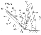
プラットフォーム構造体16、特に可動プラットフォーム部分36の展開は、アクチュエータ24の平行四辺形リフト機構の油圧動作により可変的に調整される展開速度で動作されるのがよい。本明細書では、アクチュエータ24の油圧回路は、可変オリフィス制御弁(図示せず)を有し、この可変オリフィス制御弁は、アクチュエータ24と共に動作可能な油圧サブ装置の比例制御を行う制御インターフェースを有している。ギヤ組立体60は、以下に説明するように、アクチュエータ24によって可動プラットフォーム部分36の展開を制御するように垂直アームと結合された制御リンク機構62を有している。図10では、矢印64で示すように、装置10の展開が続き、乗り移りレベル位置にあるプラットフォーム構造体16に、車両12のフロアまで延び且つ2つの機能を有する転がりストップバリア/乗り移りプレート40を構成し、それにより、車両12とアクセス装置10のプラットフォーム構造体16との間の車椅子の乗り移りを可能にする。その後、図11に示すように、乗員をプラットフォーム構造体16上に載せ、更なる展開により、2つの機能を有する転がりストップバリア/移動プレート40を立ち上げ、矢印66で示すように地面レベルまで下降させる。矢印68の方向は、車両12から外方に離れるアクセス装置10の移動を示している。図12に示すように、転がりストップバリア42が矢印72の動きで下げられ、図5を参照して説明した捩りスプリングによる負荷がかけられた転がりストップフット46、46’が地面レベル70で静止するようになるとき、プラットフォーム構造体16は、地面レベル70で静止するようになる。
Deployment of the
図13〜図15は、フロアプレート部分カバー50を有するプラットフォーム構造体16を示し、フロアプレート部分カバー50は、固定プラットフォーム部分34に対して可動プラットフォーム部分36を移動させるためのリンク機構38及びギヤ組立体60を露出させるために破断して示されている。図14では、可動プラットフォーム部分36がその格納配置まで移動するとき、転がりストップフット46、46’が地面レベルから離れるように進行するにつれて、転がりストップバリア42が引き上げられる。しかしながら、可動プラットフォーム部分36が完全に格納されると、すなわち、図15に示すように、可動プラットフォーム部分36の下に固定プラットフォーム部分34が重なると、図18と関連して示すように、転がりストップフット46、46’は、延長支持体32、32’と共に低輪郭を有する格納配置のために、転がりストップバリア42を延長する。
FIGS. 13-15 show the
図16は、図13の断面図であり、更に、図16〜図19は、展開状態、特に車椅子アクセス装置10のプラットフォーム構造に使用されているギヤ組立体60のラック及びピニオンリンク機構組立体を示し、且つ、格納時にプラットフォーム構造体16の低輪郭配置のための可動プラットフォーム部分及び転がりストップバリア42の格納を示す。図19は、特にここで説明するギヤ組立体60を示している。ギヤ組立体60は、ギヤリンク機構62により垂直アーム30と結合されており、その結果、垂直アーム30、32がアクチュエータ24により展開位置と格納位置との間で移動するとき、垂直アーム30は、図16の矢印74及び図17の76で示すように移動する傾向があり、それにより、ギヤ組立体60と共にリンク機構38を移動させ、図17の移動矢印78、80で示すように、格納配置と展開配置との間の可動プラットフォーム部分36の移動を引き起こす。図18に示すように、可動プラットフォーム部分36がプラットフォーム構造体16内で完全に格納配置に達すると、転がりストップバリア42が延長格納配置に移動し、転がりストップフット46が固定プラットフォーム部分34の上面に支持されるようになる。図19では、ギヤ組立体60が分解断面図で示され、動作矢印88、90で指示するように、ピニオンアームを移動させるためのラックギヤ歯84及びピニオンギヤ歯86、並びに、矢印94で指示するようにギヤ組立体のラックギヤに対する並進移動のためのギヤリンク62と共に示されている移動92を示している。ラック及びピニオンギヤは、リンク機構38及び可動プラットフォーム部分36の移動を正確に制御するために、直線運動を回転運動に変換するのに使用される。図19に示すように、ギヤ組立体60は、車椅子アクセス装置10のアクチュエータ24によりそれぞれの垂直アーム30、32と共に制御されるように、右側延長支持体32及び/又は左側延長支持体32’の一方又は両方に展開される。
FIG. 16 is a cross-sectional view of FIG. 13, and FIGS. 16-19 show the rack and pinion linkage assembly of the
様々な実施形態の説明によって本発明を例示し、更にこれらの実施形態をかなり詳細に説明してきたが、本発明の範囲は添付の請求の範囲により定められるものである。当業者であれば、上述の好ましい実施形態に対する修正を種々の態様において行うことができる点を理解すべきである。本発明の精神及び範囲は、当業者及び本発明の教示に精通するものにとって明らかであろう、好ましい実施形態に対するこうした変形形態を含むものである。 While the invention has been illustrated and described in considerable detail by the description of various embodiments, the scope of the invention is defined by the appended claims. One skilled in the art should appreciate that modifications to the preferred embodiments described above can be made in various ways. The spirit and scope of the present invention is intended to include such variations to the preferred embodiment that will be apparent to those skilled in the art and those familiar with the teachings of the present invention.
Claims (16)
第1のプラットフォーム部分(36)及び第2のプラットフォーム部分(34)を備えたプラットフォーム(16)を有し、前記第1のプラットフォーム部分は、前記第2のプラットフォーム部分に対する格納位置と展開位置との間を実質的に直線の方向に移動するように構成され、
更に、前記第2のプラットフォーム部分に連結されたアクチュエータ(24)を有し、アクチュエータ(24)は、前記プラットフォームを、上下方向格納位置、水平方向乗り移りレベル位置、及び地面レベル位置の間で移動させ、
更に、前記アクチュエータが前記プラットフォームをその上下方向格納位置と水平方向乗り移りレベル位置との間で移動させるときに、前記第1のプラットフォーム部分を前記第2のプラットフォーム部分に対する前記第1のプラットフォームの格納位置と展開位置との間で移動させるために、前記アクチュエータと前記第1のプラットフォーム部分との間に延びるコネクタ(62,84,86,38)を有し、
前記第1のプラットフォーム部分及び前記第2のプラットフォーム部分は各々、車内側縁及び車外側縁を有し、前記第1プラットフォーム部分が格納位置にあるとき、前記第1のプラットフォーム部分の車内側縁は、前記第2のプラットフォームの車内側縁と隣接し、前記第1のプラットフォーム部分の車外側縁は、前記第2のプラットフォームの車外側縁と隣接し、
前記コネクタは、前記アクチュエータと前記第2のプラットフォーム部分との間を延びる第1のリンク機構(62)と、前記第1のリンク機構と第1のプラットフォーム部分との間を延びる第2のリンク機構(84、86、38)とを有することを特徴とする車椅子リフト。A wheelchair lift (10),
A platform (16) with a first platform portion (36) and a second platform portion (34), the first platform portion having a retracted position and a deployed position relative to the second platform portion. Configured to move in a substantially linear direction between,
And an actuator (24) coupled to the second platform portion, the actuator (24) moving the platform between a vertical storage position, a horizontal transfer level position, and a ground level position. ,
Further, when the actuator moves the platform between its up and down storage position and a horizontal transfer level position, the first platform storage position relative to the second platform part. A connector (62, 84, 86, 38) extending between the actuator and the first platform portion for movement between the actuator and the deployment position;
The first platform portion and the second platform portion each have a vehicle inner edge and a vehicle outer edge, and when the first platform portion is in the retracted position, the vehicle inner edge of the first platform portion is , Adjacent to the vehicle inner edge of the second platform, and the vehicle outer edge of the first platform portion is adjacent to the vehicle outer edge of the second platform;
The connector includes a first linkage (62) that extends between the actuator and the second platform portion, and a second linkage that extends between the first linkage and the first platform portion. (84, 86, 38).
前記第2のリンク機構(38)のピニオンアームは、前記ラックギヤに応答して前記第1のプラットフォーム部分を移動させる、請求項5に記載の車椅子リフト。The first link mechanism extends between the actuator and the rack gear to move the rack gear in response to the movement of the actuator;
The wheelchair lift according to claim 5, wherein the pinion arm of the second linkage (38) moves the first platform portion in response to the rack gear.
Applications Claiming Priority (3)
| Application Number | Priority Date | Filing Date | Title |
|---|---|---|---|
| US10/353,544 | 2003-01-29 | ||
| US10/353,544 US6837670B2 (en) | 2003-01-29 | 2003-01-29 | Wheelchair access system with stacking platform |
| PCT/US2004/001614 WO2004067324A2 (en) | 2003-01-29 | 2004-01-20 | Wheelchair access system with stacking platform |
Publications (3)
| Publication Number | Publication Date |
|---|---|
| JP2006516448A JP2006516448A (en) | 2006-07-06 |
| JP2006516448A5 JP2006516448A5 (en) | 2006-08-17 |
| JP4703553B2 true JP4703553B2 (en) | 2011-06-15 |
Family
ID=32736198
Family Applications (1)
| Application Number | Title | Priority Date | Filing Date |
|---|---|---|---|
| JP2006502916A Expired - Fee Related JP4703553B2 (en) | 2003-01-29 | 2004-01-20 | Wheelchair access device with stackable platform |
Country Status (6)
| Country | Link |
|---|---|
| US (3) | US6837670B2 (en) |
| EP (1) | EP1590200A4 (en) |
| JP (1) | JP4703553B2 (en) |
| AU (1) | AU2004207781B2 (en) |
| CA (1) | CA2513882A1 (en) |
| WO (1) | WO2004067324A2 (en) |
Families Citing this family (46)
| Publication number | Priority date | Publication date | Assignee | Title |
|---|---|---|---|---|
| US6837670B2 (en) | 2003-01-29 | 2005-01-04 | The Braun Corporation | Wheelchair access system with stacking platform |
| WO2005074406A2 (en) * | 2003-01-29 | 2005-08-18 | The Braun Corporation | Wheelchair access system with stacking platform |
| US20070059140A1 (en) * | 2003-10-21 | 2007-03-15 | The Braun Corporation | Drive apparatus for a mobility access device |
| ES2238159B1 (en) * | 2003-10-23 | 2007-02-16 | Barat | FOLDING RAMP FOR VEHICLE ACCESS. |
| KR100559615B1 (en) * | 2004-05-07 | 2006-03-10 | 현대자동차주식회사 | Lift device for disabled vehicles |
| US7926618B2 (en) * | 2004-12-30 | 2011-04-19 | Agm Container Controls, Inc. | Portable wheel chair lift |
| US7726446B1 (en) * | 2005-01-28 | 2010-06-01 | Vernon Roger Buchanan | Mobile hunting blind |
| ITUD20050134A1 (en) * | 2005-08-22 | 2007-02-23 | Mobility Trend S R L | PERFECT LIFTING PLATFORM FOR PERSONS AND / OR GOODS, SUITABLE FOR MEANS OF TRANSPORT IN GENERAL |
| US7441995B2 (en) * | 2005-09-27 | 2008-10-28 | The Braun Corporation | Cam-actuated locking inboard barrier |
| CA2592494A1 (en) * | 2007-06-12 | 2008-12-12 | Alden Heppner | Elevated observatory |
| AT505922B1 (en) * | 2007-10-23 | 2009-05-15 | Plasser Bahnbaumasch Franz | TRUCK VEHICLE WITH A COVERED LOADING AREA |
| US8042655B1 (en) * | 2008-04-11 | 2011-10-25 | Maxon Industries, Inc. | Roll stop for a lift |
| US8113760B1 (en) | 2008-05-12 | 2012-02-14 | Sean Schroll | Secure loading system |
| GB2480489B (en) * | 2010-05-20 | 2012-10-10 | Ratcliff Palfinger Ltd | Tail lift for a vehicle |
| US8821103B1 (en) * | 2010-08-12 | 2014-09-02 | Dan A. Matthews | Lift attachable to a vehicle |
| US8550763B2 (en) * | 2010-09-30 | 2013-10-08 | International Business Machines Corporation | Cell engagement and retention carriage |
| US8375496B1 (en) | 2011-01-27 | 2013-02-19 | Lift-U, Division Of Hogan Mfg., Inc. | Fold out ramp |
| US8250693B1 (en) | 2011-01-27 | 2012-08-28 | Lift-U, Division Of Hogan Mfg., Inc. | Fold out ramp |
| US8132281B1 (en) * | 2011-01-27 | 2012-03-13 | Lift-U, Division Of Hogan Mfg., Inc. | Fold out ramp |
| GB2491378B (en) | 2011-06-01 | 2015-11-18 | Poolpod Ltd | Lifting apparatus and associated methods |
| DE102011109900B3 (en) * | 2011-08-10 | 2013-01-31 | Horst Rathert | Inclined elevator for transportation of loads, particularly wheel chairs, through stairs in crowded space for disabled and wheelchair users, comprises platform for receiving load and guide unit arranged on stair side through length of stair |
| US8973713B2 (en) | 2011-11-03 | 2015-03-10 | Agm Container Controls, Inc. | Height adjustment system for wheelchair lift |
| US9051156B2 (en) | 2011-11-03 | 2015-06-09 | Agm Container Controls, Inc. | Wheelchair lift device with pinned floor struts |
| US8783419B2 (en) | 2011-11-03 | 2014-07-22 | Agm Container Controls, Inc. | Low profile wheelchair lift with direct-acting hydraulic cylinders |
| WO2013086559A1 (en) * | 2011-12-13 | 2013-06-20 | Josef Wiedenhorn | A ramp assembly for a vehicle, and a vehicle |
| FR2985988B1 (en) * | 2012-01-25 | 2016-08-26 | Pmr Productions | ELEVATOR FOR PEOPLE WITH REDUCED MOBILITY |
| DE202012002832U1 (en) * | 2012-03-21 | 2013-06-25 | Gustav Bruns Maschinenbau und Förderanlagen GmbH & Co. KG | Vehicle lift with pretensioner |
| US9151301B2 (en) | 2012-06-11 | 2015-10-06 | Ricon Corp. | Hydraulic system and arrangement for an access arrangement |
| US9101519B2 (en) | 2013-02-07 | 2015-08-11 | Dallas Smith Corporation | Leveling ramp for a wheelchair |
| ITMI20130378A1 (en) * | 2013-03-13 | 2014-09-14 | Car Oil System S P A | LIFT FOR WHEELCHAIRS, PARTICULARLY FOR VEHICLES USED FOR THE TRANSPORT OF PERSONS DIFFERENTLY ABLE. |
| TWI552742B (en) * | 2014-01-28 | 2016-10-11 | 國立清華大學 | Bed with overturn function |
| JP6316710B2 (en) * | 2014-08-29 | 2018-04-25 | アイシン軽金属株式会社 | Slope device with multiple functions |
| US9616796B2 (en) * | 2014-10-21 | 2017-04-11 | Liftmasters, Llc | Receiver-mounted lift gate |
| CN108349718B (en) * | 2015-10-23 | 2020-04-10 | 优动产品公司 | Lifting mechanism |
| US10426673B2 (en) * | 2016-03-01 | 2019-10-01 | The Braun Corporation | Platform entrance gate safety barrier for a mobility vehicle lift |
| CA2926417C (en) * | 2016-04-08 | 2017-08-22 | Gurshan S. Sidhu | Vehicle mounted stowable access ramp |
| US10881561B2 (en) * | 2016-09-16 | 2021-01-05 | Fenton Mobility Products, Inc. | Shiftable assembly for a platform wheelchair lift |
| IT201600124657A1 (en) * | 2016-12-09 | 2018-06-09 | Euroreifen Ms S R L | LIFTING SYSTEM |
| US10500110B2 (en) | 2017-06-20 | 2019-12-10 | Tyler Taschner | Wheelchair loading system |
| US10981487B1 (en) | 2018-08-24 | 2021-04-20 | Gator Liftgates, Llc | Hitch mounted lift gate system with pivoting door-access drop feature and method of loading and unloading a payload |
| US10695238B2 (en) | 2018-09-17 | 2020-06-30 | Charlie Homer Thompson | Mountable elevator |
| US10568786B1 (en) * | 2018-09-25 | 2020-02-25 | Creative Carriage Ltd. | Pivotal handle for folding a ramp of a vehicle |
| EP3804683B1 (en) * | 2019-10-11 | 2024-01-03 | Autolift S.r.l. | Wheelchair lift for mounting to a vehicle |
| US10994795B1 (en) * | 2021-01-25 | 2021-05-04 | Vantage Mobility International, Llc | Mobility-assist hybrid conversion vehicles and methods of manufacturing the same |
| WO2022178646A1 (en) * | 2021-02-26 | 2022-09-01 | Borisoff Jaimie F | Deployable auxiliary support for a wheeled apparatus supporting a person |
| CA3188473A1 (en) * | 2022-03-25 | 2023-09-25 | AVAN Mobility Inc. | Accessibility vehicle |
Citations (6)
| Publication number | Priority date | Publication date | Assignee | Title |
|---|---|---|---|---|
| JPH1086739A (en) * | 1996-09-17 | 1998-04-07 | Otec Japan:Kk | Lift device for wheelchair in vehicle |
| JPH11113961A (en) * | 1997-10-13 | 1999-04-27 | Otec Japan:Kk | Lift for wheelchair of vehicle |
| JP2002059774A (en) * | 2000-08-18 | 2002-02-26 | Kanto Auto Works Ltd | Wheelchair lifter |
| JP2002154368A (en) * | 2000-09-11 | 2002-05-28 | Toyota Auto Body Co Ltd | Sloping device of vehicle |
| JP2002516149A (en) * | 1998-05-29 | 2002-06-04 | ライコン・コーポレイション | Wheelchair lift with folding platform |
| JP2008142572A (en) * | 2008-02-18 | 2008-06-26 | Autech Japan Inc | Rotation direction regulation mechanism |
Family Cites Families (47)
| Publication number | Priority date | Publication date | Assignee | Title |
|---|---|---|---|---|
| US3651965A (en) | 1970-05-01 | 1972-03-28 | Clover Ind Inc | Wheel chair ramp for automotive vehicles |
| US3913759A (en) | 1973-10-15 | 1975-10-21 | Scott C Deacon | Wheelchair lift |
| US4251179A (en) | 1978-03-13 | 1981-02-17 | Transportation Design & Technology, Inc. | Wheelchair lift |
| US4007844A (en) | 1976-02-02 | 1977-02-15 | Maxon Industries, Inc. | Self folding platform |
| US4134504A (en) * | 1976-09-21 | 1979-01-16 | Louis Salas | Lift for wheelchairs |
| US4121695A (en) | 1977-03-24 | 1978-10-24 | Target Industries, Inc. | Hydraulic wheelchair lift |
| US4140230A (en) | 1977-05-12 | 1979-02-20 | Pearson Marvin R | Powered loading platform |
| US4408948A (en) | 1979-01-16 | 1983-10-11 | Robinson Morris D | Controlled-folding and controlled-unfolding multiple section platform assembly |
| US4252491A (en) | 1979-03-30 | 1981-02-24 | Jelco Service Co., Inc. | Material lift platform |
| US4353436A (en) | 1980-04-16 | 1982-10-12 | Ricon Corp. | Manual wheelchair lift |
| US4479753A (en) | 1982-05-19 | 1984-10-30 | Transportation Design & Technology, Inc. | Wheelchair lift for passenger vehicles |
| US4534450A (en) | 1984-04-30 | 1985-08-13 | Pierre Savaria | Invalid lift |
| US4664584A (en) * | 1985-03-21 | 1987-05-12 | The Braun Corporation | Rotary wheelchair lift |
| US4685858A (en) | 1986-02-20 | 1987-08-11 | Transpec Inc. | Vehicle entrance ramp |
| US4984955A (en) | 1989-02-23 | 1991-01-15 | Mccullough Robert C | Lift apparatus |
| US5026244A (en) | 1990-05-17 | 1991-06-25 | Stewart & Stevenson Power, Inc. | Wheelchair lift apparatus for commercial vehicles |
| US5180275A (en) | 1991-05-28 | 1993-01-19 | The Braun Corporation | Rotary bus lift with power stowable platform |
| US5261779A (en) * | 1992-01-24 | 1993-11-16 | The Braun Corporation | Dual hydraulic, parallelogram arm wheelchair lift |
| US5605431A (en) | 1992-07-28 | 1997-02-25 | Ricon Corporation | Locking wheelchair lift |
| US5445488A (en) | 1992-07-28 | 1995-08-29 | Ricon Corporation | Locking wheelchair lift |
| US5628610A (en) | 1993-04-02 | 1997-05-13 | Stratman; Daniel R. | Combination of lifting apparatus and bracket |
| US5564884A (en) | 1994-01-06 | 1996-10-15 | Farsai; Ali J. | Wheelchair lift with automated folding platform |
| US5401135A (en) | 1994-01-14 | 1995-03-28 | Crow River Industries | Foldable platform wheelchair lift with safety barrier |
| US5524952A (en) | 1994-05-03 | 1996-06-11 | Braun Corporation | Semi-ambulatory companion seating system and method |
| US5465807A (en) | 1994-06-27 | 1995-11-14 | Harold Josephs | Safety guard for hand trucks or lift gates |
| US5703450A (en) | 1994-06-27 | 1997-12-30 | Josephs; Harold | Safety guard for pedestrian-operated machines having rotatable blades |
| US5613825A (en) | 1994-11-07 | 1997-03-25 | Stewart & Stevenson Power, Inc. | Wheelchair lift apparatus |
| US5672041A (en) | 1994-12-22 | 1997-09-30 | Crow River Industries, Inc. | Collapsible, powered platform for lifting wheelchair |
| US5542811A (en) | 1995-01-04 | 1996-08-06 | Vartanian; Roger | Wheelchair lift with laterally displaceable support post for vertical and rotational displacement |
| US5960909A (en) | 1995-11-28 | 1999-10-05 | Horcher Gmbh | Device for lifting a person from a pool |
| US5890545A (en) | 1996-05-06 | 1999-04-06 | Smithco, Inc. | Electric drive bunker rake |
| US5865593A (en) | 1996-12-31 | 1999-02-02 | Lift-U, Division Of Hogan Mfg., Inc. | Wheelchair lift with wheelchair barrier platform interlock mechanism |
| US5806632A (en) | 1997-03-26 | 1998-09-15 | The Braun Corporation | Spring assist system for gravity deployment of stowed platform wheelchair lifter |
| US5975830A (en) | 1997-06-11 | 1999-11-02 | Goodrich; Ronald W. | Under floor wheelchair lift |
| US6086314A (en) | 1997-08-15 | 2000-07-11 | Ricon Corporation | Foldable platform wheelchair lift |
| US6102648A (en) | 1997-09-05 | 2000-08-15 | Ricon Corporation | Driving mechanism for vehicle lifts |
| US6203266B1 (en) | 1997-10-27 | 2001-03-20 | Ricon Corporation | Power safety barrier for wheelchair lift |
| US6010298A (en) | 1998-04-15 | 2000-01-04 | Lift-U Division Of Hogan Mfg., Inc. | Low floor vehicle ramp assembly |
| US6238169B1 (en) * | 1998-05-01 | 2001-05-29 | The Braun Corporation | Dual function inboard barrier/bridgeplate assembly for wheelchair lifts |
| US6065924A (en) * | 1998-05-01 | 2000-05-23 | The Braun Corporation | Wheelchair lift platform having internal gas spring deployment from stowage position |
| US6340280B1 (en) | 1998-05-20 | 2002-01-22 | Universal City Studios, Inc. | Amusement ride vehicle with wheelchair ramp |
| US6190112B1 (en) * | 1998-10-27 | 2001-02-20 | 1244754 Ontario Ltd. | Lifting device for installation in the frame of a motor vehicle |
| US6435804B1 (en) | 1999-05-19 | 2002-08-20 | Mark Hutchins | Lifting apparatus |
| US6398479B1 (en) | 2000-05-03 | 2002-06-04 | The Braun Corporation | Under-vehicle lift with folding platform |
| US6554086B1 (en) | 2000-10-27 | 2003-04-29 | Invacare Corporation | Obstacle traversing wheelchair |
| US6837670B2 (en) | 2003-01-29 | 2005-01-04 | The Braun Corporation | Wheelchair access system with stacking platform |
| US20060233632A1 (en) | 2005-02-28 | 2006-10-19 | The Braun Corporation | Wheelchair lift with a rotary sensor used to determine lift position |
-
2003
- 2003-01-29 US US10/353,544 patent/US6837670B2/en not_active Expired - Fee Related
-
2004
- 2004-01-20 AU AU2004207781A patent/AU2004207781B2/en not_active Ceased
- 2004-01-20 JP JP2006502916A patent/JP4703553B2/en not_active Expired - Fee Related
- 2004-01-20 WO PCT/US2004/001614 patent/WO2004067324A2/en active Search and Examination
- 2004-01-20 EP EP04703717A patent/EP1590200A4/en not_active Withdrawn
- 2004-01-20 CA CA002513882A patent/CA2513882A1/en not_active Abandoned
-
2005
- 2005-07-27 US US11/192,211 patent/US7413395B2/en not_active Expired - Fee Related
-
2006
- 2006-07-19 US US11/489,344 patent/US7419349B2/en not_active Expired - Fee Related
Patent Citations (6)
| Publication number | Priority date | Publication date | Assignee | Title |
|---|---|---|---|---|
| JPH1086739A (en) * | 1996-09-17 | 1998-04-07 | Otec Japan:Kk | Lift device for wheelchair in vehicle |
| JPH11113961A (en) * | 1997-10-13 | 1999-04-27 | Otec Japan:Kk | Lift for wheelchair of vehicle |
| JP2002516149A (en) * | 1998-05-29 | 2002-06-04 | ライコン・コーポレイション | Wheelchair lift with folding platform |
| JP2002059774A (en) * | 2000-08-18 | 2002-02-26 | Kanto Auto Works Ltd | Wheelchair lifter |
| JP2002154368A (en) * | 2000-09-11 | 2002-05-28 | Toyota Auto Body Co Ltd | Sloping device of vehicle |
| JP2008142572A (en) * | 2008-02-18 | 2008-06-26 | Autech Japan Inc | Rotation direction regulation mechanism |
Also Published As
| Publication number | Publication date |
|---|---|
| AU2004207781B2 (en) | 2008-05-08 |
| WO2004067324A3 (en) | 2005-03-03 |
| EP1590200A2 (en) | 2005-11-02 |
| AU2004207781A1 (en) | 2004-08-12 |
| US7413395B2 (en) | 2008-08-19 |
| US20060018743A1 (en) | 2006-01-26 |
| US6837670B2 (en) | 2005-01-04 |
| EP1590200A4 (en) | 2010-09-29 |
| US7419349B2 (en) | 2008-09-02 |
| US20060263183A1 (en) | 2006-11-23 |
| CA2513882A1 (en) | 2004-08-12 |
| JP2006516448A (en) | 2006-07-06 |
| US20040146386A1 (en) | 2004-07-29 |
| WO2004067324A2 (en) | 2004-08-12 |
| AU2004207781A2 (en) | 2004-08-12 |
Similar Documents
| Publication | Publication Date | Title |
|---|---|---|
| JP4703553B2 (en) | Wheelchair access device with stackable platform | |
| AU767571B2 (en) | Wheelchair lift with foldable platform | |
| US6062805A (en) | Vehicular wheelchair step lift | |
| US4081091A (en) | Wheelchair lift | |
| US6086314A (en) | Foldable platform wheelchair lift | |
| US7445416B2 (en) | Wheelchair lift with slidable support arm | |
| EP1883739B1 (en) | A folding loft stair assembly | |
| US20230119483A1 (en) | Moveable baseplate cover and inboard barrier gate of a lift system for a motorized vehicle | |
| CA2263446A1 (en) | Under floor wheelchair lift | |
| CA1119131A (en) | Wheelchair lift | |
| US5613825A (en) | Wheelchair lift apparatus | |
| WO2003059685A2 (en) | Wheelchair access system for a vehicle | |
| JP3042326B2 (en) | Lifting device for vehicle seat | |
| JP4128320B2 (en) | Wheelchair lifting device | |
| GB2140749A (en) | Wheelchair elevator for passenger vehicles | |
| AU2006100956A5 (en) | Wheelchair access system with stacking platform | |
| NL1039038C2 (en) | Lift device to be used in conjunction with a vehicle. | |
| JP4411619B2 (en) | Automatic handrail raising / lowering device for vehicle lifting device | |
| JPH04331638A (en) | Vertical lifting gear for vehicle | |
| JPH0714076Y2 (en) | lift device | |
| IE20060399A1 (en) | A folding loft stair assembly | |
| JPH0629941U (en) | lift device | |
| WO2005074406A2 (en) | Wheelchair access system with stacking platform | |
| JPH0563989U (en) | lift device | |
| BRMU8900057U2 (en) | lift for boarding and disembarking passengers in vehicles |
Legal Events
| Date | Code | Title | Description |
|---|---|---|---|
| A521 | Request for written amendment filed |
Free format text: JAPANESE INTERMEDIATE CODE: A523 Effective date: 20060405 |
|
| A621 | Written request for application examination |
Free format text: JAPANESE INTERMEDIATE CODE: A621 Effective date: 20060405 |
|
| A131 | Notification of reasons for refusal |
Free format text: JAPANESE INTERMEDIATE CODE: A131 Effective date: 20081020 |
|
| A601 | Written request for extension of time |
Free format text: JAPANESE INTERMEDIATE CODE: A601 Effective date: 20090120 |
|
| A602 | Written permission of extension of time |
Free format text: JAPANESE INTERMEDIATE CODE: A602 Effective date: 20090127 |
|
| A521 | Request for written amendment filed |
Free format text: JAPANESE INTERMEDIATE CODE: A523 Effective date: 20090417 |
|
| A131 | Notification of reasons for refusal |
Free format text: JAPANESE INTERMEDIATE CODE: A131 Effective date: 20091013 |
|
| A521 | Request for written amendment filed |
Free format text: JAPANESE INTERMEDIATE CODE: A523 Effective date: 20100113 |
|
| A131 | Notification of reasons for refusal |
Free format text: JAPANESE INTERMEDIATE CODE: A131 Effective date: 20100712 |
|
| A521 | Request for written amendment filed |
Free format text: JAPANESE INTERMEDIATE CODE: A523 Effective date: 20100722 |
|
| A01 | Written decision to grant a patent or to grant a registration (utility model) |
Free format text: JAPANESE INTERMEDIATE CODE: A01 Effective date: 20110207 |
|
| A61 | First payment of annual fees (during grant procedure) |
Free format text: JAPANESE INTERMEDIATE CODE: A61 Effective date: 20110308 |
|
| LAPS | Cancellation because of no payment of annual fees |