JP4702088B2 - Image signal noise reduction method, noise reduction apparatus, and imaging apparatus - Google Patents
Image signal noise reduction method, noise reduction apparatus, and imaging apparatus Download PDFInfo
- Publication number
- JP4702088B2 JP4702088B2 JP2006040058A JP2006040058A JP4702088B2 JP 4702088 B2 JP4702088 B2 JP 4702088B2 JP 2006040058 A JP2006040058 A JP 2006040058A JP 2006040058 A JP2006040058 A JP 2006040058A JP 4702088 B2 JP4702088 B2 JP 4702088B2
- Authority
- JP
- Japan
- Prior art keywords
- value
- pixel
- noise reduction
- image signal
- peripheral
- Prior art date
- Legal status (The legal status is an assumption and is not a legal conclusion. Google has not performed a legal analysis and makes no representation as to the accuracy of the status listed.)
- Expired - Fee Related
Links
Images


Landscapes
- Picture Signal Circuits (AREA)
- Color Television Image Signal Generators (AREA)
- Studio Devices (AREA)
Description
本発明は、撮像素子から出力される画像信号のノイズ低減方法、ノイズ低減装置、及びこれらを用いた撮像装置に関する。 The present invention relates to a method for reducing noise of an image signal output from an image sensor, a noise reduction device, and an imaging device using these.
従来、デジタルカメラ等においては、撮像素子から出力されデジタル変換された画像信号からノイズを除去する方法として、例えば平滑化フィルタや、メディアンカットフィルタを用いる方法が知られている。しかし、画像信号にそれらのフィルタをかけた場合にはノイズだけでなく画像のエッジ成分も失われることとなる。そのためエッジ成分を劣化させることなくノイズ成分を除去あるいは減少させることが必要となる。これに関しては、例えば下記特許文献1には、A/Dコンバータから出力されたデジタル映像信号(画像信号)に対し、輝度レベルに基づき1画素ごとにノイズであるか否かを判別し、ノイズと判別された画素信号だけをデジタルフィルタに通すことにより、ノイズ成分の影響がなく、かつ解像度の劣化の少ない画像を得る方法が記載されている(例えば、特許文献1参照。)。
2. Description of the Related Art Conventionally, in a digital camera or the like, a method using a smoothing filter or a median cut filter is known as a method for removing noise from an image signal output from an image sensor and digitally converted. However, when those filters are applied to the image signal, not only noise but also edge components of the image are lost. Therefore, it is necessary to remove or reduce the noise component without deteriorating the edge component. In this regard, for example, in
しかしながら、前記方法は、画像信号に対して、それがノイズであるか否かの判別、及びその判別結果に応じた信号処理内容の切り換えを行うものであるため、ハードウェア資源等の信号処理システムの複雑化やコスト高を招くという問題があった。 However, since the above method is to determine whether or not the image signal is noise, and to switch the signal processing content according to the determination result, a signal processing system such as a hardware resource. There is a problem of increasing complexity and cost.
そこで、出願人は特許文献2記載の発明を提案した。これにより、ハードウェア資源等の信号処理システムの複雑化やコスト高を招くという問題を解消することが可能となり、さらには画像のエッジを劣化することなくノイズを低減させることも可能となった。
しかしながら、特許文献2記載の発明にあっては、前述のように画像のエッジを劣化することなくノイズを低減させることは可能であるが、画像のグラデーションがある部分については、ノイズ除去能力が低下するという課題が確認された。
However, in the invention described in
本発明は、かかる従来の課題に鑑みてなされたものであり、簡単な信号処理システムで画像のグラデーションがある部分についてもノイズ除去能力を得ることのでき、かつ劣化の少ない画質を得ることが可能となる画像信号の画像信号のノイズ低減方法、ノイズ低減装置及び撮像装置を提供することを目的とする。 The present invention has been made in view of such a conventional problem, and it is possible to obtain a noise removal capability even for a portion having an image gradation with a simple signal processing system and to obtain an image quality with little deterioration. An object of the present invention is to provide a noise reduction method, a noise reduction device, and an imaging device for an image signal.
前記課題を解決するために請求項1の発明にあっては、撮像素子から出力された画像信号に対し、注目画素を対称中心として対称位置に存在する複数の周辺画素の値の平均値である周辺画素平均値を算出し、前記周辺画素平均値を、前記注目画素の値を中心とした所定範囲に制限した制限周辺画素値を算出し、前記制限周辺画素値を、前記周辺画素の新たな値として、前記注目画素にローパスフィルタ処理を施し注目画素変換値を得る画像信号のノイズ低減方法とした。 In order to solve the above-mentioned problem, in the first aspect of the present invention, the image signal output from the image sensor is an average value of the values of a plurality of peripheral pixels existing at symmetrical positions with the target pixel as the symmetry center. A peripheral pixel average value is calculated, a limited peripheral pixel value in which the peripheral pixel average value is limited to a predetermined range centered on the value of the target pixel is calculated, and the limited peripheral pixel value is calculated as a new value of the peripheral pixel. As a value, a low-pass filter process is performed on the target pixel to obtain a target pixel conversion value.
また、請求項2の発明にあっては、前記撮像素子から出力された画像信号は、画素補間処理を施す前のベイヤー配列の信号であるとした。
In the invention of
また、請求項3の発明にあっては、前記注目画素及び周辺画素をG成分の画素とした。
In the invention of
また、請求項4の発明にあっては、前記撮像素子から出力された画像信号は、ガンマ変換処理を施す前の信号であるとした。
In the invention of
また、請求項5の発明にあっては、請求項1から4のいずれかに記載の画像信号のノイズ低減方法を、複数回反復処理することとした。
In the invention of
また、請求項6の発明にあっては、撮像素子から出力された画像信号に対し、注目画素を対称中心として対称位置に存在する複数の周辺画素の値の平均値である周辺画素平均値を算出する手段と、前記周辺画素平均値を、前記注目画素の値を中心とした所定範囲に制限した制限周辺画素値を算出する手段と、前記制限周辺画素値を、前記周辺画素の新たな値として、前記注目画素にローパスフィルタ処理を施し注目画素変換値を得る手段とを備えるノイズ低減装置とした。
In the invention of
また、請求項7の発明にあっては、被写体を撮像して画像信号を出力する撮像素子を備える撮像装置において、前記撮像素子から出力された画像信号に対し、注目画素を対称中心として対称位置に存在する複数の周辺画素の値の平均値である周辺画素平均値を算出する手段と、前記周辺画素平均値を、前記注目画素の値を中心とした所定範囲に制限した制限周辺画素値を算出する手段と、前記制限周辺画素値を、前記周辺画素の新たな値として、前記注目画素にローパスフィルタ処理を施し注目画素変換値を得る手段とを備える撮像装置とした。
According to a seventh aspect of the present invention, in an image pickup apparatus including an image pickup device that picks up an image of a subject and outputs an image signal, the image signal output from the image pickup device is symmetric with respect to a target pixel as a symmetry center Means for calculating a peripheral pixel average value that is an average value of a plurality of peripheral pixels existing in the area, and a limited peripheral pixel value in which the peripheral pixel average value is limited to a predetermined range centered on the value of the target pixel. The imaging apparatus includes: a calculating unit; and a unit that performs low-pass filter processing on the target pixel to obtain the target pixel conversion value by using the limited peripheral pixel value as a new value of the peripheral pixel.
本発明によれば、画像信号におけるエッジなどの大きな振幅成分を保持したまま低振幅成分のノイズを低減させ、同時にエッジを劣化させることなくエッジ上のノイズを低減させることができるとともに、画像のグラデーションがある部分についてもノイズ除去能力を得ることができる。しかも、画素の値に関係なく常に同一の処理を画像信号に施すだけで、それを実現することができる。
According to the present invention, it is possible to reduce low-amplitude component noise while retaining a large amplitude component such as an edge in an image signal, and simultaneously reduce noise on the edge without degrading the edge, and image gradation. Noise removal capability can also be obtained for certain parts. In addition, this can be realized by simply performing the same processing on the image signal regardless of the pixel value.
以下、本発明の第1の実施の形態を図にしたがって説明する。図1は、本発明に係るデジタルカメラ1の概略構成を示すブロック図である。
Hereinafter, a first embodiment of the present invention will be described with reference to the drawings. FIG. 1 is a block diagram showing a schematic configuration of a
このデジタルカメラ1は、撮像素子であるCCD2により被写体を撮像し、撮像により取得した被写体画像をLCD(液晶表示装置)4に表示させるとともに、撮影操作に応じて、撮像した被写体画像を画像データに変換し画像メモリ5に記録する構成である。なお、画像メモリ5は、カメラ本体に内蔵又は着脱自在なフラッシュメモリ等の不揮発性メモリである。
The
CCD2は、感光部にベイヤー配列の原色フィルター(図5(a)参照)が設けられたものであり、CCD2から出力されたアナログの撮像信号は、信号処理部3において各種の信号処理を施されて、最終的には輝度信号(Y信号)と色差信号(Cb信号、Cr信号)を含んだYUVデータ、すなわちデジタルの画像信号として出力される。
The
信号処理部3から出力された画像信号は、撮影待機状態にあるときLCD4に送られて被写体画像として表示される。また、撮影操作時には、CPU6によりJPEG等の所定フォーマットに従い圧縮され画像メモリ5に記録される。画像メモリ5に記録された圧縮後の画像データは、必要に応じCPU6により読み出され、いったん伸張された後LCD4において静止画像、或いは動画像として再生表示される。
The image signal output from the
また、デジタルカメラ1は、CPU6が前記画像データの圧縮・伸張、及び装置全体の制御に必要とする各種の制御プログラムが記録されたROM7と、CPU6の作業用メモリであるRAM8、キー入力部9、レンズ駆動部10を有している。キー入力部9は、シャッターキーや、動作モードの切り替えに使用されるモード切替キー等からなり、キー操作に応じた操作信号をCPU6へ出力する。レンズ駆動部10は、CCD2の前面に配置されたフォーカスレンズを含むレンズ群を光軸方向に駆動するモーターや、それを制御するためのドライバー等から構成され、AF制御時におけるCPU6からの指令に基づきレンズ位置を変化させる。
The
図2は、前述した信号処理部3の詳細を示すブロック図である。信号処理部3は、CCD2から入力したアナログの撮像信号が入力するアナログ処理部31と、ノイズ低減部32、色補間部33、ホワイトバランス調整部34、ガンマ補正部(ガンマLUT)35、色変換部36、エッジ強調部37の各部から構成されている。
FIG. 2 is a block diagram showing details of the
アナログ処理部31は、CCD2から出力された撮像信号に含まれるCCD2の駆動ノイズを減少させる相関二重サンプリング回路(CDS回路)と、ノイズ低減後における信号のゲインを調整する自動利得制御回路(AGC回路)、ゲイン調整後の信号をデジタル信号に変換するA/D変換器を含み、CCD2から入力したアナログの撮像信号をデジタルの画像信号(ベイヤーデータ)に変換する。ノイズ低減部32は、アナログ処理部31から出力された撮像信号に混入しているノイズを低減させる。なお詳細については後述する。
The
色補間部33は、前記ノイズが低減されたベイヤーデータからR,G,Bの色成分について色補間を行って全画素分のRGBデータを生成する。ホワイトバランス調整部34は、画像を構成する全画素の色情報に基づきR,G,Bの色成分毎のゲイン調整を行うことによってホワイトバランスを調整する。ガンマ補正部35は画像信号に対するガンマ特性(階調特性)の補正を行う。
The
色変換部36は、R,G,Bの色成分データから輝度信号(Y信号)と色差信号(Cb信号、Cr信号)を含んだYUVデータを生成する。エッジ強調部37は、ハイパスフィルタ或いはマスクフィルタによりYUVデータにおけるY信号の振幅を調整することによりエッジ強調を行い、かつエッジ強調により生じたノイズをコアリング処理等により除去し、処理後の画像信号をCPU6やLCD4へ出力する。
The
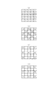
図3は、GのLPF重み付データ71を示す図であり、図6は、R及びBのLPF重み付データ72を示す図である。
FIG. 3 is a diagram showing G LPF
次に、前述したノイズ低減部32について詳述する。ノイズ低減部32は、所謂ローパスフィルタであって、図示しないが、5ライン分のラインメモリ、5ピクセル分の遅延素子と、各遅延素子からの出力に対して減算器、絶対値算出回路、リミッタ等が接続された構成である。そして、図4のフローチャートに示した処理アルゴリズムに従ったノイズ低減処理を行うことにより、アナログ処理部31から入力したベイヤーデータにおけるノイズを低減させる。
Next, the
すなわちノイズ低減部32では、図5(a)に示した5×5の画素空間を処理単位としてRGBの色成分データ毎に以下の動作を行う。まずGデータについて説明すると、図5(b)に示したように、注目画素(中心画素)、及びこれを対称中心として対象位置にあるその周辺8画素の値(画素値)に着目する。そして、注目画素を対称中心として対象位置にある一対の画素の平均値を求め、tmp0〜tmp3とする(ステップS101)。
つまり、
tmp0=(G0+G3)/2
tmp1=(G1+G2)/2
tmp2=(G4+G7)/2
tmp3=(G5+G6)/2
とする。
That is, the
That means
tmp0 = (G0 + G3) / 2
tmp1 = (G1 + G2) / 2
tmp2 = (G4 + G7) / 2
tmp3 = (G5 + G6) / 2
And
次に、下記のように各tmp0〜tmp3と注目画素値Gcと差を求め、これをd0〜d3とする(ステップS102)。
d0=tmp0−Gc
d1=tmp1−Gc
d2=tmp2−Gc
d3=tmp3−Gc
Next, as described below, the difference between each tmp0 to tmp3 and the target pixel value Gc is obtained, and this is set as d0 to d3 (step S102).
d0 = tmp0−Gc
d1 = tmp1-Gc
d2 = tmp2-Gc
d3 = tmp3-Gc
さらに、下記のように、定数A(>0)により、前記d0〜d3の値を区間[−A,A]に制限し、その結果をdn′とする(ステップS103)。
d0′=f0×min(A,│d0│)
d1′=f1×min(A,│d1│)
d2′=f2×min(A,│d2│)
d3′=f3×min(A,│d3│)
ここで、f0〜f3はd0〜d3の符号であり、min(a,b)はaとbの小さい方を選択する演算子であり、|a|はaの絶対値を求める演算子である。
Further, as described below, the value of d0 to d3 is limited to the interval [-A, A] by a constant A (> 0), and the result is set to dn '(step S103).
d0 ′ = f0 × min (A, | d0 |)
d1 ′ = f1 × min (A, | d1 |)
d2 ′ = f2 × min (A, | d2 |)
d3 ′ = f3 × min (A, | d3 |)
Here, f0 to f3 are signs of d0 to d3, min (a, b) is an operator for selecting the smaller one of a and b, and | a | is an operator for obtaining the absolute value of a. .
また、このステップS103で求めたd0′〜d3′から、周辺画素g0〜g3を次のように再定義する。
g0=d0′+Gc
g1=d1′+Gc
g2=d2′+Gc
g3=d3′+Gc
これら周辺画素を使って図3に示したGのLPF重み付データ71でLPF処理を行い、ノイズ低減後のGc′を得る(ステップS104)。
Gc′=(4×g0+4×g1+2×g2+2×g3+4×Gc)/16
In addition, the peripheral pixels g0 to g3 are redefined as follows from d0 ′ to d3 ′ obtained in step S103.
g0 = d0 ′ + Gc
g1 = d1 ′ + Gc
g2 = d2 ′ + Gc
g3 = d3 ′ + Gc
Using these peripheral pixels, LPF processing is performed with the G LPF
Gc ′ = (4 × g0 + 4 × g1 + 2 × g2 + 2 × g3 + 4 × Gc) / 16
=(4×d0′+4×d1′+2×d2′+2×d3′+16×Gc)/16
なお、図3に示したGのLPF重み付データ71(1倍、2倍、4倍)はあくまでも一例であり他の値を用いるようにしてもよい。
= (4 × d0 ′ + 4 × d1 ′ + 2 × d2 ′ + 2 × d3 ′ + 16 × Gc) / 16
The G LPF weighted data 71 (1 ×, 2 ×, 4 ×) shown in FIG. 3 is merely an example, and other values may be used.
引き続き、B,Rの色成分データについても、上述したGデータと同様の処理を行いノイズを低減させる。但し、その際には図5(c)、同図(d)に示したように、注目画素値Bc,Rcに対して8画素分の周辺画素値B0〜B7,R0〜R7を用いた処理を行い、かつ前述した重み付け倍率は、例えば図6に示したR及びBのLPF重み付データ72とする。
Subsequently, the B, R color component data is also processed in the same manner as the G data described above to reduce noise. However, in this case, as shown in FIGS. 5C and 5D, processing using peripheral pixel values B0 to B7 and R0 to R7 for eight pixels with respect to the target pixel values Bc and Rc. The weighting magnification described above is, for example, the R and B LPF
以上のように前記ノイズ低減部32における処理では、アナログ処理部31から入力したベイヤーデータのRGBの各色成分データ毎に、注目画素値を、周辺画素値の影響を一定以上受けない元の値と近い値に変換するため、エッジなどの大きな振幅成分を保持したまま、撮像信号に混入している低振幅ノイズを低減させることができる。また、エッジ部分の画素についても、注目画素値に近い周辺画素値(修正値)のみで平均化を行うため、エッジを劣化させることなくエッジ上のノイズも低減させることができる。また、画像のグラデーションがある部分についてもノイズ除去能力を得ることができる。しかも、注目画素値や周辺画素値に関係なく常に同一の処理を画像信号に施すだけである。従って、信号処理システムが簡単であり低コストでノイズ除去ができるとともに、劣化の少ない画質を得ることができる。
As described above, in the processing in the
なお、本実施の形態では、RGBの各色成分データの全てを処理対象としてノイズ低減処理(ローパスフィルタ処理)を行うようにしたが、輝度成分が最も多いGデータのみにノイズ低減処理を施すようにしても構わない。その場合であっても実用上の効果を得ることができる。 In this embodiment, noise reduction processing (low-pass filter processing) is performed on all RGB color component data as processing targets. However, noise reduction processing is performed only on G data having the largest luminance component. It doesn't matter. Even in this case, practical effects can be obtained.
また、本実施の形態を、複数回反復処理してもよい。これにより、低周波数ノイズの低減効果をあげることができる。 Further, the present embodiment may be repeatedly processed a plurality of times. Thereby, the reduction effect of low frequency noise can be raised.
図7は、前述した第1の実施の形態と等価な変形例を示すものである。
すなわちノイズ低減部32では、図5(a)に示した5×5の画素空間を処理単位としてRGBの色成分データ毎に以下の動作を行う。まずGデータについて説明すると、図5(b)に示したように、注目画素(中心画素)、及びこれを対称中心として対象位置にあるその周辺8画素の値(画素値)に着目する。そして、注目画素を対称中心として対象位置にある一対の画素の平均値を求め、tmp0〜tmp7とする(ステップS301)。
つまり、
tmp0=tmp3=(G0+G3)/2
tmp1=tmp2=(G1+G2)/2
tmp2=tmp7=(G4+G7)/2
tmp3=tmp6=(G5+G6)/2
とする。
FIG. 7 shows a modification equivalent to the first embodiment described above.
That is, the
That means
tmp0 = tmp3 = (G0 + G3) / 2
tmp1 = tmp2 = (G1 + G2) / 2
tmp2 = tmp7 = (G4 + G7) / 2
tmp3 = tmp6 = (G5 + G6) / 2
And
次に、下記のように前記画素の平均値と注目画素値Gcと差を求め、これをd0〜d7とする(ステップS302)。
d0=tmp0−Gc
d1=tmp1−Gc
・・・
d7=tmp7−Gc
Next, a difference between the average value of the pixels and the target pixel value Gc is obtained as described below, and this is set as d0 to d7 (step S302).
d0 = tmp0−Gc
d1 = tmp1-Gc
...
d7 = tmp7−Gc
さらに、下記のように、定数A(>0)により、前記d0〜d7の値を区間[−A,A]に制限し、その結果をdn′とする(ステップS303)。
d0′=f0×min(A,│d0│)
d1′=f1×min(A,│d1│)
・・・
d7′=f7×min(A,│d7│)
但し、f0〜f7はd0〜d7の符号であり、min(a,b)はaとbの小さい方を選択する演算子であり、|a|はaの絶対値を求める演算子である。
Further, as described below, the values of d0 to d7 are limited to the interval [−A, A] by a constant A (> 0), and the result is set to dn ′ (step S303).
d0 ′ = f0 × min (A, | d0 |)
d1 ′ = f1 × min (A, | d1 |)
...
d7 ′ = f7 × min (A, | d7 |)
However, f0 to f7 are signs of d0 to d7, min (a, b) is an operator for selecting the smaller one of a and b, and | a | is an operator for obtaining an absolute value of a.
また、このステップS303で求めたd0′〜d7′から、周辺画素値g0〜g7を次のように再定義する(ステップS304)。
g0=d0′+Gc
g1=d1′+Gc
・・・
g7=d7′+Gc
これら周辺画素を使って図3に示したGのLPF重み付データ71でLPF処理を行い、ノイズ低減後のGc′を得る(ステップS305)。
Gc′=(4×Gc+2×g0+2×g1+2×g2+2×g3+g4+g5+g6+g 7)/16
In addition, the peripheral pixel values g0 to g7 are redefined as follows from the d0 ′ to d7 ′ obtained in step S303 (step S304).
g0 = d0 ′ + Gc
g1 = d1 ′ + Gc
...
g7 = d7 ′ + Gc
Using these peripheral pixels, LPF processing is performed with the LPF
Gc ′ = (4 × Gc + 2 × g0 + 2 × g1 + 2 × g2 + 2 × g3 + g4 + g5 + g6 + g7) / 16
=(4Gc+2(g0+g1+g2+g3)+g4+g5+g6+g7)/16 = (4Gc + 2 (g0 + g1 + g2 + g3) + g4 + g5 + g6 + g7) / 16
引き続き、B,Rの色成分データについても、上述したGデータと同様の処理を行いノイズを低減させる。但し、その際には図5(c)、同図(d)に示したように、注目画素値Bc,Rcに対して8画素分の周辺画素値B0〜B7,R0〜R7を用いた処理を行い、かつ前述した重み付け倍率は、例えば図6に示したR及びBのLPF重み付データ72とする。
Subsequently, the B, R color component data is also processed in the same manner as the G data described above to reduce noise. However, in this case, as shown in FIGS. 5C and 5D, processing using peripheral pixel values B0 to B7 and R0 to R7 for eight pixels with respect to the target pixel values Bc and Rc. The weighting magnification described above is, for example, the R and B LPF
図8は、本発明の第2の実施の形態を示すものである。
下記式に示すように、注目画素のLPF出力GcLpfを求め、この時の重み付けは図3に示した重み付データ71を用いる(ステップS201)。
GcLpf=
{2×(G0+G1+G2+G3)+(G4+G5+G6+G7)+4×Gc}/16
FIG. 8 shows a second embodiment of the present invention.
As shown in the following equation, the LPF output GcLpf of the target pixel is obtained, and
GcLpf =
{2 × (G0 + G1 + G2 + G3) + (G4 + G5 + G6 + G7) + 4 × Gc} / 16
次に、下記のようにGcとGcLpfとの差dGcを求める(ステップS202)。
dGc=Gc−GcLpf
Next, a difference dGc between Gc and GcLpf is obtained as described below (step S202).
dGc = Gc−GcLpf
さらに、下記のように、定数A(>0)により、dGcの値を区間[−A,A]に制限し、その結果をdGc′とする(ステップS203)。
dGc′=fdGc×min(A,│dGc│)
ここでfdGcは、dGcの符号である。
Further, as described below, the value of dGc is limited to the interval [−A, A] by a constant A (> 0), and the result is set to dGc ′ (step S203).
dGc ′ = fdGc × min (A, | dGc |)
Here, fdGc is a sign of dGc.
また、GcからdGc′を引いて、ノイズ低減後のGc′を得る(ステップS204)。
Gc′=Gc−dGc′
なお、図3に示したGのLPF重み付データ71(1倍、2倍、4倍)はあくまでも一例であり他の値を用いるようにしてもよい。
Also, dGc ′ is subtracted from Gc to obtain Gc ′ after noise reduction (step S204).
Gc ′ = Gc−dGc ′
The G LPF weighted data 71 (1 ×, 2 ×, 4 ×) shown in FIG. 3 is merely an example, and other values may be used.
引き続き、B,Rの色成分データについても、上述したGデータと同様の処理を行いノイズを低減させる。 Subsequently, the B, R color component data is also processed in the same manner as the G data described above to reduce noise.
なお、本実施の形態においては、前述したアルゴリズムによるノイズ低減処理をアナログ処理部31から入力したベイヤーデータに対して行う場合について説明したが、前記ノイズ低減処理は、例えば色変換部36において生成されたYUVデータの輝度(Y)データに対して行うこともでき、その場合においてもエッジなどの大きな振幅成分を保持したままで低振幅のノイズを除去することができ、かつエッジの品質を維持したままエッジ上のノイズを低減することができる。
In the present embodiment, the case where the noise reduction processing by the algorithm described above is performed on the Bayer data input from the
また、本実施の形態ではCCD2がベイヤー配列の原色フィルターを有し、色分離以前の画像信号がベイヤーデータである場合について説明したが、CCD2(MOS型の撮像素子であってもよい)が他の色配列のフィルターを有する構成である場合についても、本実施の形態と同様のノイズ低減処理を色分離以前の画像信号に対して行うことにより、前記効果を得ることができる。
In the present embodiment, the
さらに、本実施の形態では、ノイズ低減処理をガンマ変換前に行うため、低階調域から高階調域にかけて均一なノイズ低減を行うことができる。しかも、ガンマ変換後に行う場合にあっては階調毎にノイズ定数Aを可変させる必要があるが(ガンマ変換を行った後には低階調域のノイズが増幅されるためである。)、本実施の形態のようにガンマ変換前に行う場合においてはそのような必要がない。したがって、これによってもハードウェア資源を削減することができる。 Furthermore, in this embodiment, since noise reduction processing is performed before gamma conversion, uniform noise reduction can be performed from a low gradation region to a high gradation region. Moreover, in the case of performing after gamma conversion, it is necessary to vary the noise constant A for each gradation (because noise in the low gradation area is amplified after performing gamma conversion). In the case of performing before gamma conversion as in the embodiment, this is not necessary. Therefore, hardware resources can be reduced also by this.
図9は、本発明の第3の実施の形態を示すものであり、ノイズ低減部32での処理を繰り返し行うようにしたものである。
図10のフローチャートに示すように、前述した第1の実施の形態又は第2の実施の形態に示したノイズ低減処理をある画素のG,B,Rの色成分データについて行う(ステップS401)。当該画素のG,B,Rの色成分データについてのノイズ低減処理が終了したならば、全ての画素についてノイズ低減処理が終了したか否かを判断し(ステップS402)、終了していない場合には、次の画素を選択し(ステップS)、当該画素に対してノイズ低減処理を行う(ステップS401)。
FIG. 9 shows a third embodiment of the present invention, in which the processing in the
As shown in the flowchart of FIG. 10, the noise reduction processing shown in the first embodiment or the second embodiment is performed on the color component data of G, B, and R of a certain pixel (step S401). If the noise reduction processing for the G, B, and R color component data of the pixel has been completed, it is determined whether or not the noise reduction processing has been completed for all the pixels (step S402). Selects the next pixel (step S), and performs noise reduction processing on the pixel (step S401).
そして、全ての画素についてノイズ低減処理が終了したならば、カウンタCの値をカウントアップさせ(ステップS404)、このカウントアップさせたカウンタCの値が所定値Nとなったか否かを判断する(ステップS405)。C≠Nであるならば、ステップS401に戻ってノイズ低減処理を反復し、C=Nとなった時点で終了する。したがって、本実施の形態によれば、前述した第1又は第2の実施の形態のノイズ低減処理がN回反復実行されることにより、低周波数ノイズの低減効果を上げることができる。 When the noise reduction processing is completed for all the pixels, the value of the counter C is incremented (step S404), and it is determined whether or not the counted value of the counter C has reached a predetermined value N (step S404). Step S405). If C ≠ N, the process returns to step S401 to repeat the noise reduction process, and ends when C = N. Therefore, according to the present embodiment, the noise reduction processing of the first or second embodiment described above is repeatedly executed N times, so that the low frequency noise reduction effect can be increased.
すなわち、前記図3及び図6のフィルタ係数は、1次元のフィルタ係数(1,2,1)を、2次元に拡張したものであるが、1次元フィルタの周波数特性を図11(A)に示す。このフィルタを2回かけると、
(1,2,1)*(1,2,1)=(1,4,6,4,1) (但し、*は畳み込み演算を示す)
となり、(1,4,6,4,1)を係数とする1次元フィルタを1回かけるのと等価であることが分かる。その周波数特性を図11(B)に示す。同図(A)と(B)とを比較すると、(B)の方が遮断周波数が低周波側にシフトしている。よって、低周波数のノイズ低減効果が高くなるとすることができ、また、回数を多くするほどその効果は高まる。
前記図3のフィルタを2回かけた場合に相当するフィルタ係数を図12に示し、図6のフィルタを2回かけた場合に相当するフィルタ係数を図13に示す。
That is, the filter coefficients of FIGS. 3 and 6 are obtained by extending the one-dimensional filter coefficients (1, 2, 1) to two dimensions, and the frequency characteristics of the one-dimensional filter are shown in FIG. Show. If you apply this filter twice,
(1,2,1) * (1,2,1) = (1,4,6,4,1) (where * indicates a convolution operation)
It can be seen that this is equivalent to applying a one-dimensional filter having a coefficient of (1, 4, 6, 4, 1) once. The frequency characteristics are shown in FIG. Comparing (A) and (B) in the figure, the cutoff frequency is shifted to the lower frequency side in (B). Therefore, it can be said that the low frequency noise reduction effect becomes high, and the effect increases as the number of times increases.
FIG. 12 shows filter coefficients corresponding to the case of applying the filter of FIG. 3 twice, and FIG. 13 shows filter coefficients corresponding to the case of applying the filter of FIG. 6 twice.
なお、本実施の形態においては、本発明を主として静止画の撮影及び記録を行うデジタルカメラに適用した場合について説明したが、本発明はこれ以外にも、デジタルビデオカメラ等のように画像信号の処理を必要とする他の映像機器においても実施可能であり、その場合においても前述した効果を得ることができる。 In the present embodiment, the case where the present invention is applied to a digital camera that mainly captures and records a still image has been described. However, the present invention is not limited to this. The present invention can also be implemented in other video equipment that requires processing, and even in that case, the effects described above can be obtained.
1 デジタルカメラ
2 CCD
3 信号処理部
31 アナログ処理部
32 ノイズ低減部
33 色補間部
34 ホワイトバランス調整部
35 ガンマ補正部
36 色変換部
37 エッジ強調部
1
3
Claims (7)
注目画素を対称中心として対称位置に存在する複数の周辺画素の値の平均値である周辺画素平均値を算出し、
前記周辺画素平均値を、前記注目画素の値を中心とした所定範囲に制限した制限周辺画素値を算出し、
前記制限周辺画素値を、前記周辺画素の新たな値として、前記注目画素にローパスフィルタ処理を施し注目画素変換値を得ることを特徴とする画像信号のノイズ低減方法。 For the image signal output from the image sensor
A peripheral pixel average value that is an average value of values of a plurality of peripheral pixels existing at a symmetric position with the target pixel as a symmetric center,
Calculating a limited peripheral pixel value in which the peripheral pixel average value is limited to a predetermined range centered on the value of the target pixel;
A noise reduction method for an image signal, wherein a low-pass filter process is performed on the target pixel using the limited peripheral pixel value as a new value of the peripheral pixel to obtain a target pixel conversion value.
画素補間処理を施す前のベイヤー配列の信号であることを特徴とする請求項1に記載の画像信号のノイズ低減方法。 The image signal output from the image sensor is
The image signal noise reduction method according to claim 1 , wherein the signal is a Bayer array signal before pixel interpolation processing.
注目画素を対称中心として対称位置に存在する複数の周辺画素の値の平均値である周辺画素平均値を算出する手段と、
前記周辺画素平均値を、前記注目画素の値を中心とした所定範囲に制限した制限周辺画素値を算出する手段と、
前記制限周辺画素値を、前記周辺画素の新たな値として、前記注目画素にローパスフィルタ処理を施し注目画素変換値を得る手段と
を備えることを特徴とするノイズ低減装置。 For the image signal output from the image sensor
Means for calculating a peripheral pixel average value that is an average value of values of a plurality of peripheral pixels existing at a symmetric position with the target pixel as a symmetric center;
Means for calculating a limited peripheral pixel value in which the peripheral pixel average value is limited to a predetermined range centered on the value of the target pixel;
A noise reduction apparatus comprising: means for performing a low-pass filter process on the target pixel, using the limited peripheral pixel value as a new value of the peripheral pixel, and obtaining a target pixel conversion value.
前記撮像素子から出力された画像信号に対し、注目画素を対称中心として対称位置に存在する複数の周辺画素の値の平均値である周辺画素平均値を算出する手段と、
前記周辺画素平均値を、前記注目画素の値を中心とした所定範囲に制限した制限周辺画素値を算出する手段と、
前記制限周辺画素値を、前記周辺画素の新たな値として、前記注目画素にローパスフィルタ処理を施し注目画素変換値を得る手段と
を備えることを特徴とする撮像装置。 In an imaging device including an imaging device that images a subject and outputs an image signal,
Means for calculating a peripheral pixel average value which is an average value of a plurality of peripheral pixels existing in a symmetric position with the target pixel as a symmetric position with respect to the image signal output from the image sensor;
Means for calculating a limited peripheral pixel value in which the peripheral pixel average value is limited to a predetermined range centered on the value of the target pixel;
An image pickup apparatus comprising: means for performing a low-pass filter process on the target pixel and using the restricted peripheral pixel value as a new value of the peripheral pixel to obtain a target pixel conversion value.
Priority Applications (1)
| Application Number | Priority Date | Filing Date | Title |
|---|---|---|---|
| JP2006040058A JP4702088B2 (en) | 2005-03-31 | 2006-02-17 | Image signal noise reduction method, noise reduction apparatus, and imaging apparatus |
Applications Claiming Priority (3)
| Application Number | Priority Date | Filing Date | Title |
|---|---|---|---|
| JP2005100768 | 2005-03-31 | ||
| JP2005100768 | 2005-03-31 | ||
| JP2006040058A JP4702088B2 (en) | 2005-03-31 | 2006-02-17 | Image signal noise reduction method, noise reduction apparatus, and imaging apparatus |
Publications (2)
| Publication Number | Publication Date |
|---|---|
| JP2006311501A JP2006311501A (en) | 2006-11-09 |
| JP4702088B2 true JP4702088B2 (en) | 2011-06-15 |
Family
ID=37477776
Family Applications (1)
| Application Number | Title | Priority Date | Filing Date |
|---|---|---|---|
| JP2006040058A Expired - Fee Related JP4702088B2 (en) | 2005-03-31 | 2006-02-17 | Image signal noise reduction method, noise reduction apparatus, and imaging apparatus |
Country Status (1)
| Country | Link |
|---|---|
| JP (1) | JP4702088B2 (en) |
Families Citing this family (3)
| Publication number | Priority date | Publication date | Assignee | Title |
|---|---|---|---|---|
| US7844127B2 (en) * | 2007-03-30 | 2010-11-30 | Eastman Kodak Company | Edge mapping using panchromatic pixels |
| JP5352191B2 (en) | 2008-10-31 | 2013-11-27 | 三星電子株式会社 | Noise reduction apparatus, noise reduction method, and program |
| JP4640508B2 (en) * | 2009-01-09 | 2011-03-02 | ソニー株式会社 | Image processing apparatus, image processing method, program, and imaging apparatus |
Family Cites Families (4)
| Publication number | Priority date | Publication date | Assignee | Title |
|---|---|---|---|---|
| JP3449489B2 (en) * | 1992-07-16 | 2003-09-22 | オリンパス光学工業株式会社 | Tracking device |
| JP3947912B2 (en) * | 2002-01-24 | 2007-07-25 | 富士フイルム株式会社 | Image signal processing device |
| JP2003348378A (en) * | 2002-05-28 | 2003-12-05 | Sharp Corp | Video signal processing circuit |
| JP2004363853A (en) * | 2003-06-04 | 2004-12-24 | Casio Comput Co Ltd | Image signal noise reduction method and noise reduction device |
-
2006
- 2006-02-17 JP JP2006040058A patent/JP4702088B2/en not_active Expired - Fee Related
Also Published As
| Publication number | Publication date |
|---|---|
| JP2006311501A (en) | 2006-11-09 |
Similar Documents
| Publication | Publication Date | Title |
|---|---|---|
| JP3530907B2 (en) | Digital camera | |
| US7932935B2 (en) | Imaging apparatus capable of reducing deterioration of an image even when the gain increased | |
| CN101394471A (en) | Image processing device and digital video camera | |
| JP2004363853A (en) | Image signal noise reduction method and noise reduction device | |
| JP2009201094A (en) | Imaging apparatus and imaging method | |
| JP4433883B2 (en) | White balance correction device, white balance correction method, program, and electronic camera device | |
| KR101003681B1 (en) | Pixel interpolation circuit, pixel interpolation method, and recording medium | |
| US7755681B2 (en) | Apparatus and method of gamma correction in digital image processing device | |
| JP2009055471A (en) | Image processing device, image processing method, and imaging device | |
| JP4470901B2 (en) | Imaging apparatus, high-frequency component detection circuit, high-frequency component detection method, and computer program | |
| JP5092536B2 (en) | Image processing apparatus and program thereof | |
| US8009935B2 (en) | Pixel interpolation circuit, pixel interpolation method, and recording medium | |
| JP4702088B2 (en) | Image signal noise reduction method, noise reduction apparatus, and imaging apparatus | |
| EP2515543A2 (en) | Image capturing apparatus and image capturing method | |
| JP4596987B2 (en) | Imaging device | |
| JP5213604B2 (en) | Imaging device | |
| JP2009055415A (en) | Camera | |
| JP2006135564A (en) | Pixel interpolation device and pixel interpolation method | |
| JP4781670B2 (en) | Imaging device | |
| JP2008124653A (en) | Image signal processing apparatus, image signal processing program, and image signal processing method | |
| JP4687454B2 (en) | Image processing apparatus and imaging apparatus | |
| JP4942596B2 (en) | Image processing apparatus, imaging apparatus, and display apparatus | |
| JP2007266956A (en) | Imaging apparatus, impulse component detection circuit, impulse component removal circuit, impulse component detection method, impulse component removal method, and computer program | |
| US10348984B2 (en) | Image pickup device and image pickup method which performs diagonal pixel offset and corrects a reduced modulation depth in a diagonal direction | |
| JP4385890B2 (en) | Image processing method, frequency component compensation unit, image processing apparatus including the frequency component compensation unit, and image processing program |
Legal Events
| Date | Code | Title | Description |
|---|---|---|---|
| A621 | Written request for application examination |
Free format text: JAPANESE INTERMEDIATE CODE: A621 Effective date: 20090116 |
|
| A977 | Report on retrieval |
Free format text: JAPANESE INTERMEDIATE CODE: A971007 Effective date: 20101116 |
|
| A131 | Notification of reasons for refusal |
Free format text: JAPANESE INTERMEDIATE CODE: A131 Effective date: 20101130 |
|
| A521 | Request for written amendment filed |
Free format text: JAPANESE INTERMEDIATE CODE: A523 Effective date: 20110111 |
|
| TRDD | Decision of grant or rejection written | ||
| A01 | Written decision to grant a patent or to grant a registration (utility model) |
Free format text: JAPANESE INTERMEDIATE CODE: A01 Effective date: 20110208 |
|
| A61 | First payment of annual fees (during grant procedure) |
Free format text: JAPANESE INTERMEDIATE CODE: A61 Effective date: 20110221 |
|
| R150 | Certificate of patent or registration of utility model |
Ref document number: 4702088 Country of ref document: JP Free format text: JAPANESE INTERMEDIATE CODE: R150 |
|
| LAPS | Cancellation because of no payment of annual fees |