JP4687173B2 - Discharge lamp lighting device and vehicle lamp - Google Patents
Discharge lamp lighting device and vehicle lamp Download PDFInfo
- Publication number
- JP4687173B2 JP4687173B2 JP2005079545A JP2005079545A JP4687173B2 JP 4687173 B2 JP4687173 B2 JP 4687173B2 JP 2005079545 A JP2005079545 A JP 2005079545A JP 2005079545 A JP2005079545 A JP 2005079545A JP 4687173 B2 JP4687173 B2 JP 4687173B2
- Authority
- JP
- Japan
- Prior art keywords
- discharge lamp
- unit
- power
- type
- lamp
- Prior art date
- Legal status (The legal status is an assumption and is not a legal conclusion. Google has not performed a legal analysis and makes no representation as to the accuracy of the status listed.)
- Expired - Fee Related
Links
Images


Landscapes
- Circuit Arrangements For Discharge Lamps (AREA)
Description
本発明は、接続されたメタルハライドランプなどの高輝度放電灯の識別とそれに応じた適切な点灯制御を行う放電灯点灯装置および車両用灯具に関するものである。 The present invention relates to a discharge lamp lighting device and a vehicular lamp that perform identification of a high-intensity discharge lamp such as a connected metal halide lamp and appropriate lighting control corresponding thereto.
メタルハライドランプなどの高輝度放電灯はその光束の大きさから車載用前照灯に用いられている。これまでの車載用メタルハライドランプには、主に始動時の光束の立ち上げと安定時の電極間電圧を高めに設定するため水銀が封入されているタイプが主流であった。水銀封入型ランプは一般にはD1、D2ランプと呼称され、D1ランプは始動時のパルス発生用のイグナイタを内蔵したタイプである。それに対して、環境問題の観点から、水銀を封入せずに、その役割を他のハロゲン化合物で代用した水銀フリーランプもあり、今後、規模が拡大していく方向にある。水銀フリーランプは一般にはD3、D4ランプと呼称され、D3ランプは始動時のパルス発生用のイグナイタを内蔵したタイプである。 High-intensity discharge lamps such as metal halide lamps are used for in-vehicle headlamps because of their luminous flux. Conventional metal halide lamps for vehicles have mainly been of a type in which mercury is enclosed in order to set a higher luminous flux at the start and a higher voltage between the electrodes at the time of starting. Mercury-enclosed lamps are generally referred to as D1 and D2 lamps, and the D1 lamp is a type having a built-in igniter for generating a pulse at start-up. On the other hand, from the viewpoint of environmental problems, there is a mercury-free lamp that does not enclose mercury and substitutes other halogen compounds for its role, and the scale is expanding in the future. Mercury-free lamps are generally referred to as D3 and D4 lamps, and the D3 lamp is a type that incorporates an igniter for generating a pulse at the time of starting.
しかし、水銀フリーランプでは、点灯時の放電電圧が低いという特徴があり、始動時の光束の急激な立ち上がりを実現するために代用したハロゲン化合物を急激に気化させる必要があり、水銀封入型ランプより大きな電力を必要とする特徴がある。これらの特徴から、水銀封入型ランプと水銀フリーランプを略同等の時間に対する光立ち上がり特性で立ち上げるためには、図34(a)に示すようなそれぞれに適した電力投入制御が必要となる。また、その時の出力電圧と出力電流の変化の様子を図34(b)および(c)に示す。 However, mercury-free lamps are characterized by a low discharge voltage when lit, and it is necessary to rapidly vaporize the substituted halogen compound in order to realize a rapid rise in luminous flux at start-up. There is a feature that requires large electric power. From these characteristics, in order to start up the mercury-enclosed lamp and the mercury-free lamp with the light rising characteristics with respect to substantially the same time, it is necessary to perform power-on control suitable for each as shown in FIG. In addition, FIGS. 34B and 34C show how the output voltage and output current change at that time.
図34(a)に示すような電力をランプに供給するためのバラストとして、図35のような構成が一例として挙げられる。これは直流電源1と、直流電源1からの電圧を放電灯5が必要とする電圧に昇降圧するDC−DCコンバータ部2と、DC−DCコンバータ部2の直流出力電圧を低周波の矩形波に変換するインバータ部3と、ランプ始動用として数10kVの電圧を発生させるイグナイタ部4と、放電灯5と、DC−DCコンバータ部2の出力電圧と出力電流を検出し出力電力が目標電力となるようにDC−DCコンバータ部2を制御する制御部6とから構成される。
As a ballast for supplying power to the lamp as shown in FIG. 34A, a configuration as shown in FIG. 35 is given as an example. This includes a
以下、各部の回路構成について説明する。直流電源1と直列にDC−DCコンバータ部2のトランスT1の1次側巻線P1とスイッチング素子Q1が接続される。トランスT1の2次側巻線S1にはダイオードD1と平滑コンデンサC1が直列に接続される。なお、ダイオードD1の方向はスイッチング素子Q1がONして、トランスT1の1次側巻線P1に電圧が印加されたときに、トランスT1の2次側巻線S1に発生する電流を止める方向である。スイッチング素子Q1が高周波でオン・オフすることで、直流電源1の直流電圧を電圧変換した直流電圧がコンデンサC1に得られる。以上でDC−DCコンバータ部2を構成している。
Hereinafter, the circuit configuration of each part will be described. The primary side winding P1 of the transformer T1 of the DC-
また、DC−DCコンバータ部2の平滑コンデンサC1と並列にスイッチング素子Q2〜Q5で構成されるフルブリッジ回路が接続される。スイッチング素子Q2〜Q5は図示しないフルブリッジ制御回路により対角方向に配置されたスイッチング素子Q2,Q5とQ3,Q4とが低周波で交互にオンすることで、コンデンサC1の直流電圧を低周波の矩形波電圧に変換して出力する。以上でインバータ部3を構成している。
A full bridge circuit composed of switching elements Q2 to Q5 is connected in parallel with the smoothing capacitor C1 of the DC-
続いて、フルブリッジ回路の出力と並列に、コンデンサCsと、トランスT2の1次側巻線P2とスパークギャップSG1の直列回路と、トランスT2の2次側巻線S2と放電灯5の直列回路とが接続される。放電灯5を除く以上の回路でイグナイタ部4を構成している。
Subsequently, in parallel with the output of the full bridge circuit, a capacitor Cs, a series circuit of the primary side winding P2 of the transformer T2 and the spark gap SG1, and a series circuit of the secondary side winding S2 of the transformer T2 and the
制御部6は、DC−DCコンバータ部2の出力電圧と出力電流の検出値を入力して、電流目標演算部61において、電力目標記憶部62の出力である放電灯5に供給すべき電力の目標値である出力電力目標値を出力電圧検出値で除することによって、出力電流目標値を得る。さらに、上記出力電流目標値と出力電流検出値を誤差アンプ63で比較し、その差が生じなくなるように出力制御信号を出力する。その出力制御信号に応じて図示しないPWM制御回路によりDC−DCコンバータ部2のスイッチング素子Q1のパルス幅が可変制御される。
The
電力目標記憶部62からの出力電力目標値は、ランプ状態検知部64からの出力である始動時ランプ状態によって、ランプが既に暖まっている状態と考えられる場合(再始動時)には、ランプの状態に応じてランプが暖まっていない場合(初始動時)と比べて出力電力目標値が低めに設定される(初始動時には出力電力目標値が図中のt0から開始するが、再始動時には例えばt1から開始するように制御される)。
The output power target value from the power
以下、従来例の回路動作を説明する。電源がONされて、スイッチング素子Q1がオンすると、トランスT1の1次側巻線P1とスイッチング素子Q1を介して電流が流れる。しかし、トランスT1の2次側巻線S1にはダイオードD1により電流が流れないため、そのエネルギーはトランスT1に蓄えられる。次にスイッチング素子Q1がオフすると、トランスT1の2次側巻線S1、コンデンサC1、ダイオードD1のルートで電流が流れ、トランスT1に蓄えられていたエネルギーが平滑コンデンサC1へと移される。 The circuit operation of the conventional example will be described below. When the power supply is turned on and the switching element Q1 is turned on, a current flows through the primary side winding P1 of the transformer T1 and the switching element Q1. However, since no current flows through the secondary winding S1 of the transformer T1 due to the diode D1, the energy is stored in the transformer T1. Next, when the switching element Q1 is turned off, a current flows through the route of the secondary winding S1, the capacitor C1, and the diode D1 of the transformer T1, and the energy stored in the transformer T1 is transferred to the smoothing capacitor C1.
ランプが始動する前は、放電灯5が開放状態であるため、コンデンサC1の電圧は上昇し、フルブリッジインバータをスイッチング素子Q2、Q5がON、スイッチング素子Q3、Q4がOFFの状態で固定しておくことにより、コンデンサCsの電圧も上昇する。上記電圧が所定電圧以上になると、スパークギャップSG1がブレークダウンし、トランスT2の1次側巻線P2に瞬時に電圧がかかり、トランスT2の2次側巻線S2には上記電圧を巻数比倍した高電圧が印加される。この高電圧(数10kV程度)により放電灯5がブレークダウンする。その瞬間にDC−DCコンバータ部2から放電灯5に電流が流れ、放電灯5はアーク放電に移行する。
Before the lamp starts, since the
放電灯5の点灯後は、フルブリッジインバータの出力極性を所定時間間隔で交番させながら、電流目標演算部61において、電力目標記憶部62からの出力電力目標値を出力電圧検出値で割ることによって、出力電流目標値を得る。この出力電流目標値と、検出される出力電流値を誤差アンプ63で比較し、その誤差量に応じた出力制御信号によりDC−DCコンバータ部2のスイッチング素子Q1のパルス幅を制御してその出力を調整する。以上により放電灯5の安定点灯を実現している。
After the
図34(a),(b),(c)の電気的特性やランプ形状等から、接続されたランプの種別を判断し、そのランプに適した出力電力をランプに印加する手段として、特開2003−249392号公報には、前回点灯されていたときの電気的特性を記憶しておき、その結果からランプの種別を判断し、そのランプに適した出力電力を印加する技術が開示されている。
特開2003−249392号公報に開示された従来技術では、前回点灯されていた電気的特性を記憶しておいて、その結果から判断してランプに適した出力電力を印加するために、前回点灯時に水銀フリーランプを点灯させており、それを水銀封入型ランプに取り替えた場合、水銀封入型ランプに水銀フリーランプを点灯させるための電力を投入してしまい、ランプに過剰なストレスを加えることとなり、信頼性や寿命へ悪影響を及ぼしてしまうといった課題がある。 In the prior art disclosed in Japanese Patent Laid-Open No. 2003-249392, the electrical characteristics previously lit are stored, and the previous lighting is performed in order to apply the output power suitable for the lamp based on the result. Sometimes a mercury-free lamp is lit, and if it is replaced with a mercury-filled lamp, power is applied to the mercury-filled lamp to turn on the mercury-free lamp, resulting in excessive stress on the lamp. There is a problem that it adversely affects reliability and lifetime.
また、点灯毎に毎回判断するというのは、点灯時間が短い場合や再始動時のランプ温度が異なる場合など、判断基準が環境に応じて変化してしまうと考えられるため、非常に不安定な要素となってしまう。 In addition, it is very unstable because the judgment criteria will change depending on the environment, such as when the lighting time is short or when the lamp temperature at restarting is different. It becomes an element.
本発明によれば、上記の課題を解決するために、図1に示すように、直流電源1と点灯用スイッチSから構成される電源供給部1sに接続され、前記電源供給部1sからの入力電力を放電灯5に必要な電力に変換する電力変換部23と、放電灯5に接続され放電灯5の始動に必要な高圧パルスを発生するイグナイタ部4と、前記電源供給部1sと前記電力変換部23の接続部CN1、前記電力変換部23と前記イグナイタ部4の接続部CN2、前記イグナイタ部4と放電灯5の接続部CN3のうち、少なくとも一つの接続部が外れたことを検知する検知部7と、放電灯5への供給電力を制御する制御部6とからなる放電灯点灯装置であって、前記制御部6は、放電灯5に供給される電圧を検出する電圧検出部6vと、放電灯5に供給される電流を検出する電流検出部6iと、前記電圧検出部6vまたは前記電流検出部6iの少なくとも一方の出力により放電灯5の種別を判別するための放電灯判別部6bと、前記放電灯判別部6bによって判別された放電灯5の種別を記憶する記憶部6cとを有し、前記検知部7で少なくとも一つの接続部が外れたことを検知した場合にのみ、放電灯5の種別を判別するための判別用電力制御モードで前記電力変換部23を駆動し、前記放電灯判別部6bで放電灯5の種別を判別した後、判別された放電灯5の種別を前記記憶部6cに記憶すると共に、記憶された放電灯5の種別に応じて所定の電力制御で前記電圧検出部6vと前記電流検出部6iの出力に応じて前記電力変換部23を駆動し、放電灯5を点灯することを特徴とするものである。
According to the present invention, in order to solve the above-described problem, as shown in FIG. 1, the power supply is connected to a
本発明によれば、例えば放電灯が交換された場合においても、検知部により放電灯が脱着されたことを検知し、その際には放電灯の種別を判別するために予め設定された電力にて放電灯を点灯するため、従来例で述べたように過剰なストレスを放電灯へ加えたり、信頼性や寿命へ悪影響を及ぼすようなこともなく、また確実に放電灯の種別を判断することが可能となり、更には通常の点灯時には記憶された放電灯の判別種別に基づいて各放電灯種別毎に予め設定された所定の目標電力にて直ちに点灯制御がなされるため、より速やかに放電灯を点灯することが出来る効果がある。 According to the present invention, for example, even when the discharge lamp is replaced, the detection unit detects that the discharge lamp has been attached / detached, and at that time, the power set in advance is used to determine the type of the discharge lamp. In order to light up the discharge lamp, there is no excessive stress applied to the discharge lamp as described in the conventional example, and there is no negative impact on reliability and life, and the type of discharge lamp must be determined reliably. In addition, during normal lighting, lighting control is performed immediately with a predetermined target power set in advance for each discharge lamp type based on the stored discrimination type of the discharge lamp. There is an effect that can be turned on.
(基本構成)
図1に本発明の基本例の全体回路構成を示す。この放電灯点灯装置は、直流電源1と放電灯点灯用スイッチSから構成される電源供給部1sに接続され、電源供給部1sからの入力電圧を放電灯5に必要な電力に変換する電力変換部23と、放電灯5に接続され放電灯5の始動に必要な高圧パルスを発生するイグナイタ部4、前記電源供給部1sと電力変換部23、電力変換部23とイグナイタ部4、イグナイタ部4と放電灯5の接続部CN1,CN2,CN3の接続状態(接続が外れたかどうか)を検知する検知部7、及び放電灯5への供給電力を適切に制御するための制御部6とからなる。
(Basic configuration)
FIG. 1 shows an overall circuit configuration of a basic example of the present invention. This discharge lamp lighting device is connected to a
前記制御部6は、放電灯5に供給される電圧を検出する電圧検出部6v(出力をVlaと図示)、放電灯5に供給される電流を検出する電流検出部6i(出力をIlaと図示)、検出されたVlaとIlaの値に応じて放電灯5に適切な電力が供給されるように電力変換部23へ駆動信号を与える出力電力制御部6aを有する。
The
また、制御部6は、前記検知部7により前記各接続部CN1,CN2,CN3の接続が外れたことを検知した場合にのみ、或いは放電灯5を初めて点灯する場合と前記検知部7により前記各接続部CN1,CN2,CN3の接続が外れたことを検知した場合にのみ、放電灯5への供給電力が放電灯5の種別を判別するために予め制御部6において設定された電力(図1には図示していないが、各放電灯種別毎に設定された通常時における放電灯点灯用の所定の目標供給電力カーブよりも低い目標供給電力)となるように、電力変換部23に駆動信号を与えて、放電灯5を点灯する。そして、制御部6は、その際に検出されたVlaまたはIlaの値(もしくはその両方の値)によって、点灯された放電灯5の種別が何であるかを判別する放電灯判別部6b、及び放電灯判別部6bにより判別された結果(放電灯の種別)を記憶するための記憶部6cを有している。
Further, the
そして、制御部6は、通常の放電灯点灯時(放電灯の初期点灯時と、前記検知部7による前記各接続部CN1,CN2,CN3の接続外れ検知時以外の場合)には、前記記憶部6cに記憶された放電灯5の種別に応じて各放電灯種別毎に予め設定された所定の供給電力となるように、電力変換部23に駆動信号を与え、放電灯5を点灯する。
Then, the
以上の構成及び動作により、例えば放電灯5が交換された場合においても、検知部7により放電灯5が脱着されたことを検知し、その際には放電灯5の種別を判別するために予め設定された電力にて放電灯を点灯するため、従来例で述べたように過剰なストレスを放電灯へ加えたり、信頼性や寿命へ悪影響を及ぼすようなこともなく、また確実に放電灯の種別を判断することが可能となり、更には通常の点灯時には記憶された放電灯の判別種別に基づいて各放電灯種別毎に予め設定された所定の目標電力にて直ちに点灯制御がなされるため、より速やかに放電灯を点灯することが出来る。
With the above configuration and operation, for example, even when the
(実施形態1)
図2に本発明の実施形態1の全体回路構成を示す。この放電灯点灯装置は、直流電源1と放電灯点灯用スイッチSから構成される電源供給部1sに接続され、電源供給部1sからの入力電圧を放電灯5に必要な電力に変換する電力変換部23と、放電灯接続用のソケット(接続部CN3)を介して放電灯5に接続され放電灯5の始動に必要な高圧パルスを発生するイグナイタ部4、前記ソケット内に設けられた放電灯脱着状態の検知部7、及び制御部6により構成される。
(Embodiment 1)
FIG. 2 shows the overall circuit configuration of the first embodiment of the present invention. This discharge lamp lighting device is connected to a
前記電力変換部23は、DC−DCコンバータ部2とインバータ部3からなり、DC−DCコンバータ部2は電源供給部1sからの入力電圧を放電灯点灯のために必要な電圧に変換し、インバータ部3はDC−DCコンバータ部2で変換された電圧を低周波で交番し、矩形波状の電圧に変換する。
The power conversion unit 23 includes a DC-
制御部6は、DC−DCコンバータ部2の出力電圧、出力電流を、図1の基本構成で述べた電圧検出部6v、及び電流検出部6iの入力として得られるVla、Ilaの値に基づいて、DC−DCコンバータ部2のスイッチング素子(FET等で構成される)を駆動する信号を与える。
The
インバータ部3は、FETやIGBTを4石用いてフルブリッジ構成としたもので、制御部6からの信号により駆動される。
The
ソケット内に設けられた検知部7は、ソケットから放電灯5を脱着した際にインピーダンス値が変化するもので、制御部6より検知部7のインピーダンス値を確認することによって、ソケットからの放電灯5の脱着の有無を検知することが出来る。
The
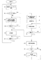
図3に実施形態1の放電灯点灯装置の動作状態のフローチャートを示す。図3の「電源オン」のフローチャートから説明する。点灯用スイッチSがオンされて点灯装置に電源が供給され、例えば電力変換部23への入力電圧が所定値(例えば、9V)を超えた場合に「電源オン」と見なし、次のステップ#1ヘ移行する。
FIG. 3 shows a flowchart of the operating state of the discharge lamp lighting device of the first embodiment. This will be described with reference to the “power-on” flowchart in FIG. When the lighting switch S is turned on and power is supplied to the lighting device. For example, when the input voltage to the power conversion unit 23 exceeds a predetermined value (for example, 9V), it is regarded as “power on”, and the
「検知部インピーダンス確認」のステップ#1では、上記ソケット内に設けられた検知部7のインピーダンス値を確認する。インピーダンス値の確認は、制御部6より検知部7に所定抵抗を介して所定電圧を印加し、その際に検知部7に発生する電圧(前記所定電圧が所定抵抗値と検知部インピーダンス値により分圧された電圧値)を測定すること等により行う。
In
「インピーダンス変化(判断)」のステップ#2では、上記で確認した値が前回確認時の値と異なると判断した場合は“有り”へ、略同じと判断した場合は“無し”へと分岐する。これにより、インピーダンス変化が“無し”と判断した場合は、通常の点灯動作(#3)となり、速やかな点灯がなされ、インピーダンス変化が“有り”と判断した場合は、放電灯の種別を判断するための点灯動作(#7)に移行する。なお、放電灯を初めて点灯する場合も必ず「放電灯種別判別点灯」のステップ#7へ移行させるためには、例えば上述の前回確認時の値に検知部インピーダンス値が取り得る範囲以外の値をセットしておく等すればよい。
In
「所定電力点灯動作」のステップ#3では、図1の基本構成で述べた記憶部6cに記憶された放電灯の種別(本実施形態ではD2或いはD4)に応じて予め設けられた所定の目標電力にて放電灯5の点灯動作を行う。なお、点灯動作の詳細については、放電灯種別判別方法と併せて後述する。
In
「電源オフ(判断)」のステップ#4では、点灯用スイッチSがオフされて点灯装置への電源供給が遮断され、例えば電力変換部23への入力電圧が所定値(例えば、6V)より低下した場合に「電源オフ」と見なし、YESへ、それ以外の場合はNOへ進み、電源オフの判断がなされるまで、点灯動作(所定電力点灯動作:ステップ#3)を行う。
In
「消灯動作」のステップ#5では、前述の電源オフの判断(#4)により、駆動信号停止等の放電灯5の消灯、回路停止処理を行う。
In
「電源オン(判断)」のステップ#6では、点灯用スイッチSがオンされて点灯装置に電源が再び供給され、例えば電力変換部23への入力電圧が所定値(例えば、9V)を超えた場合に電源オンと見なし、YESへ進み、検知部インピーダンスの確認(#1)を行う。それ以外の場合は、NOへ進み、電源の監視を続ける。なお、電源遮断等により点灯装置への電源の供給が全く無くなり、また、そのような場合に点灯装置の電気的回路動作が全く停止となる場合には、次回電源投入時には、図3の「電源オン」のフローチャートの初ステップ#1より動作が開始となる。
In
次に、「放電灯種別判別点灯/判別種別記憶」のステップ#7では、「インピーダンス変化(判断)」のステップ#2において、インピーダンス変化が“有り”と判断された場合には、予め制御部6において放電灯種別判別点灯用に設定された目標電力となるように電力変換部23に駆動信号を与えて放電灯5を点灯し、その際に検出されたVlaの値によって、点灯された放電灯5の種別が何であるかを判別し、その判別された結果(放電灯5の種別、本実施形態ではD2或いはD4)を記憶部6cに記憶する。なお、放電灯種別判別点灯方法についての詳細は後述する。
Next, in
「継続点灯動作」のステップ#8では、「放電灯種別判別点灯/判別種別記憶」のステップ#7により放電灯5の種別判別、及び記憶部6cへの判別種別の記憶の後、放電灯5へ電力供給動作を継続して行い、そのまま放電灯5を安定点灯状態へと移行させる。
In
「電源オフ(判断)」のステップ#9では、点灯用スイッチSがオフされて点灯装置への電源供給が遮断され、例えば電力変換部23への入力電圧が所定値(例えば、6V)より低下した場合に電源オフと見なし、YESへ進み「消灯動作」のステップへ、それ以外の場合はNOへ進み、電源オフ判断がなされるまで「継続点灯動作」を行う。
In
次に、図3のステップ#10〜#12の動作について説明する。「放電灯脱着検知」のステップ#10では、放電灯5の脱着状態をソケット内に設けた検知部7で監視する。「脱着(判断)」のステップ#11では、放電灯5の脱着の有無により、有りの場合は「検知部インピーダンス可変」のステップ#12へ、無しの場合は引き続き放電灯5の脱着状態を「放電灯脱着検知」のステップ#10にて監視する。「検知部インピーダンス可変」のステップ#12では、放電灯5の脱着が有りの場合には、検知部7に設けられたポジションセンサのインピーダンス値を変化させる。なお、図3のステップ#10〜#12に関する具体的な事例については後述する。
Next, operations in steps # 10 to # 12 in FIG. 3 will be described. In
図4に実施形態1の放電灯種別判別方法について示す。図4(a)は、通常点灯時の「所定電力点灯動作」のステップ#3で用いる放電灯種別毎の所定供給電力を規定するカーブであり、横軸は点灯後の経過時間を、縦軸は放電灯5への供給電力の目標値を表している。放電灯点灯時に速やか且つスムーズに光を立ち上げるためには、放電灯5の種別に適した電力の供給が必要であり、ここでは水銀封入型ランプD2と水銀フリーランプD4における目標電力規定カーブについて図示している。例えば、水銀封入型ランプD2の場合、最大電力の値は75Wでその継続時間は2秒程度、水銀フリーランプD4の場合、最大電力の値は90Wでその継続時間は8秒程度等である。ちなみに安定状態時は共に定格35Wのランプの場合である。
FIG. 4 shows the discharge lamp type discrimination method of the first embodiment. FIG. 4A is a curve that defines the predetermined supply power for each type of discharge lamp used in
図4(b)は、通常点灯時における各種別の放電灯の代表的なランプ電圧(放電灯電圧)の立ち上がりの様子を示したものである。水銀封入型ランプD2は、点灯後、水銀の作用により急激にランプ電圧が立ち上がり、安定状態に至るが、水銀フリーランプD4は、水銀が無いため、点灯後のランプ電圧の立ち上がりが緩やかであり、また、安定点灯状態でのランプ電圧も水銀封入型ランプD2の約半分と低い。(水銀封入型ランプD2の定格ランプ電圧は85V、水銀フリーランプD4は42Vである。) FIG. 4B shows the state of rising of a typical lamp voltage (discharge lamp voltage) of various types of discharge lamps during normal lighting. The mercury enclosed lamp D2 suddenly rises in lamp voltage due to the action of mercury after lighting and reaches a stable state, but the mercury-free lamp D4 has no mercury, so the lamp voltage rises slowly after lighting. In addition, the lamp voltage in a stable lighting state is as low as about half that of the mercury-filled lamp D2. (The rated lamp voltage of the mercury enclosed lamp D2 is 85V, and the mercury-free lamp D4 is 42V.)
図4(c)は、放電灯種別の判別方法について示したものである。本実施形態においては、「放電灯種別判別点灯」のステップ#7における放電灯種別判別時の供給電力を、図4(a)に示した水銀封入型ランプD2用の目標電力規定カーブと同じ目標電力規定カーブとしている。この目標電力規定カーブを用いて、上述の「放電灯種別判別点灯」の処理ステップ#7において、水銀封入型ランプD2若しくは水銀フリーランプD4を点灯した場合の代表的なランプ電圧の立ち上がりの様子も、併せて図4(c)中に示した。
FIG. 4C shows a method for determining the type of discharge lamp. In the present embodiment, the supplied power at the time of discharge lamp type determination in
本実施形態では、前述の通り、水銀封入型ランプD2用の目標電力規定カーブと同じ目標電力規定カーブを用いているため、水銀封入型ランプD2を点灯した場合は、図4(b)と同様のランプ電圧の立ち上がりとなり、水銀フリーランプD4を点灯した場合は、供給電力が低くなるため、図4(b)に示したより更にランプ電圧の立ち上がりは緩やかになる。 In the present embodiment, as described above, the same target power regulation curve as the target power regulation curve for the mercury-filled lamp D2 is used. Therefore, when the mercury-filled lamp D2 is lit, the same as in FIG. When the mercury-free lamp D4 is lit, the supplied power is low, and the ramp voltage rises more slowly than shown in FIG. 4B.
次に本実施形態における放電灯種別の判別方法について図4(c)により説明する。図4(c)中において、上述の「放電灯種別判別点灯」の処理ステップ#7における点灯後経過時間がt1、t2時点での水銀封入型ランプD2を点灯した場合のランプ電圧をV1、V2、水銀フリーランプD4を点灯した場合のランプ電圧をV1’、V2’と示している。
Next, a method for determining the type of the discharge lamp in this embodiment will be described with reference to FIG. In FIG. 4C, the lamp voltages when the mercury-enclosed lamp D2 at the time point t1 and t2 after the lighting in the above-described “discharge lamp type determination lighting”
本実施形態では、「放電灯種別判別点灯」の処理ステップ#7における放電灯種別の判別を、点灯後経過時間が時間t1〜t2間における、ランプ電圧の変化量で判別を行う。すなわち、(V2−V1)、或いは(V2’−V1’)を制御部6で求め、その値(ランプ電圧の変化量)が予め設定した所定値より大きい場合は、放電灯の種別を水銀封入型ランプD2と判別し、所定値より小さい場合は、放電灯の種別を水銀フリーランプD4と判別する。(例えば、点灯後経過時間t1、t2をそれぞれ1秒、3秒時点とし、ランプ電圧の変化量により放電灯の種別を判別するための所定値を5Vとする。)
In the present embodiment, the determination of the discharge lamp type in the
図5に実施形態1の放電灯脱着検知部7の一例を示す。図5(a)では、自動車前照灯用に用いられる放電灯5の概略形状と、放電灯接続のために用いられる従来のソケット70の概略形状、及び電気的接続のための接続端子について、略図にて示している。放電灯5は側面からの図に加えて、背面からの外観も図5(d)に示している。
FIG. 5 shows an example of the discharge lamp attachment /
放電灯5はソケット70に嵌合するための口金部51を有し、口金部51の中央には発光管52の電極の一方に接続される中心電極53が、口金部51の周辺には発光管52の電極の他方に接続される外周電極54があり、ソケット70へ放電灯5を装着した状態では、放電灯5の中心電極53がソケット70の中心電極接続用端子73と接し、放電灯5の外周電極54がソケット70の外周電極接続用端子74と接することで電気的な接続がなされ、それらは電線によりイグナイタ部4へ接続される。
The
また、放電灯5のソケット固定用突起部55を、ソケット70に設けられた放電灯固定用切欠部75に、挿入後、回転し嵌合することで、放電灯5のソケット70への確実な装着を可能としている。
Further, by inserting the
図5(b)及び図5(c)は、本実施形態によるソケット70の構成を、要部動作説明のため、ソケット70ヘの放電灯未装着状態と、装着状態の2つの場合に分けて示したものである。ソケット70の上部に図示した部分が、本実施形態における放電灯脱着状態の検知部7の一例である。ただし、検知部7の主要な構成部分のみ図示し、その他は省略している。
5 (b) and 5 (c) divide the configuration of the
検知部7は、放電灯5の装着時に放電灯口金部51により押圧されることで図中における左右方向に可動する放電灯脱着検知用突起部71を有し、放電灯脱着検知用突起部71は放電灯未装着時にはバネ72によりソケット70より突出する方向(図中における右方向)へ戻され(図5(b)の状態)、放電灯装着時にはソケット70の内部へ収納される方向(図中における左方向)へ可動となる(図5(c)の状態)。
The
また、回転柱部76が回転することでインピーダンス値が順次変化する可変抵抗器77が、前記放電灯脱着検知用突起部71に隣接して配置されており、回転柱部76には螺旋状の溝部が切ってあり、一方、前記放電灯脱着検知用突起部71には、螺旋状溝掛部71aが設けられていて、この蝶旋状溝掛部71aは放電灯脱着検知用突起部71がソケット70の内部へ収納される方向(図中における左方向)へ可動となる場合には、回転柱部76に設けられた螺旋状溝部に掛かり、ソケット70より突出する方向(図中における右方向)へ可動となる場合には、その形状または弾性により螺旋状溝部に掛からないようにしてある。
In addition, a variable resistor 77 whose impedance value sequentially changes as the
前記構成により、放電灯5をソケット70に装着する時には、前記回転柱部76が回転し、可変抵抗器77のインピーダンス値が変化し、放電灯5をソケット70から外す時には、可変抵抗器77のインピーダンス値は変わらないようにしているため、放電灯5を交換すると、検知部7のインピーダンス値が変化する。可変抵抗器77からは電線で制御部6ヘインピーダンス検出のための接続がなされる。
With the above configuration, when the
なお、螺旋状溝掛部71aは放電灯脱着検知用突起部71の内部への引っ込み構造などの構成としてもよい。
The spiral groove 71a may have a structure such as a retracting structure inside the discharge lamp
以上の構成及び動作により、実施形態1においては、放電灯が交換された場合においても、検知部により放電灯が脱着されたことを検知し、その際には放電灯の種別を判別するために予め設定された水銀封入型ランプ点灯時と同じ供給電力規定カーブにて放電灯を点灯するため、従来例で述べたように過剰なストレスを放電灯へ加えたり、信頼性や寿命へ悪影響を及ぼすようなこともなく、また、確実に放電灯の種別を判断することが可能となり、更には通常の点灯時には記憶された放電灯の判別種別に基づいて各放電灯種別毎に予め設定された所定の目標電力にて直ちに点灯制御がなされるため、より速やかに放電灯を点灯することが出来る。 With the above configuration and operation, in the first embodiment, even when the discharge lamp is replaced, the detection unit detects that the discharge lamp has been detached, and in that case, to determine the type of the discharge lamp. Since the discharge lamp is lit with the same supply power regulation curve as when a mercury-filled lamp is lit in advance, excessive stress is applied to the discharge lamp as described in the conventional example, and the reliability and life are adversely affected. In addition, it is possible to reliably determine the type of the discharge lamp, and further, a predetermined value set in advance for each discharge lamp type based on the stored determination type of the discharge lamp during normal lighting. Since the lighting control is immediately performed with the target power, the discharge lamp can be turned on more quickly.
また、放電灯の種別を判別するための点灯動作を水銀封入型ランプ点灯時と同じ供給電力規定カーブにて行うため、水銀封入型ランプの場合には、放電灯種別判別点灯時においても速やかな光の立ち上がりを得ることが出来る。 In addition, since the lighting operation for discriminating the type of the discharge lamp is performed with the same supply power regulation curve as when the mercury-enclosed lamp is lit, in the case of a mercury-enclosed lamp, it is quick even when the discharge lamp type is lit. The rise of light can be obtained.
なお、本実施形態においては、放電灯接続用のソケット内に検知部を設け、放電灯をソケットと脱着した場合に、放電灯種別判別点灯を行うようにした場合を例示して説明したが、図1の基本構成で述べたように、その他の各接続部CN1,CN2に対しても同様の構成とすることにより、接続が外された場合には放電灯種別判別点灯を行うようにすることも出来る。 In the present embodiment, the detection unit is provided in the socket for connecting the discharge lamp, and when the discharge lamp is detached from the socket, the case where the discharge lamp type determination lighting is performed is described as an example. As described in the basic configuration of FIG. 1, the same configuration is applied to each of the other connection portions CN1 and CN2, so that the discharge lamp type determination lighting is performed when the connection is disconnected. You can also.
例えば、前記電力変換部23とイグナイタ部4の接続状態により放電灯種別判別点灯を行うようにすることで、放電灯点灯装置の電力変換部23のみの交換の際などでも、過剰なストレスを放電灯5へ加えたり、信頼性や寿命へ悪影響を及ぼすようなことなどを無くすことが可能となる。
For example, by performing discharge lamp type determination lighting according to the connection state of the power conversion unit 23 and the
また、放電灯5にイグナイタ部4が内蔵された自動車前照灯用の放電灯D1、D3等や、イグナイタ部4が内蔵されたソケット等についても、本発明を同じく用いることが出来、同様の効果を得ることが可能である。
Further, the present invention can be used for the discharge lamps D1, D3 and the like for automobile headlamps in which the
検知部の構成は、実施形態1で述べた限りではなく、その他の構成であっても同様の働きをするものであればよい。 The configuration of the detection unit is not limited to that described in the first embodiment, and any other configuration may be used as long as it functions similarly.
また、図1の基本構成、及び図2の実施形態1において、制御部6はマイコン等を用いてもよいし、その他の回路手段により構成してもよい。マイコンを使用した場合は、種別の異なる放電灯への対応が簡単となるなどの利点がある。
Further, in the basic configuration of FIG. 1 and the first embodiment of FIG. 2, the
記憶部6cは、不揮発性のメモリーICを用いる等してもよいし、同様の機能が内蔵されたマイコン等を用いてもよい。
As the
なお、「検知部インピーダンス確認」のステップ#1は、1回のみではなく複数回行うことで、ノイズ等の影響を受けにくくしてもよい。また、「インピーダンス変化(判断)」のステップ#2において、インピーダンス変化が“有り”と判断された場合には、再度インピーダンスの確認を行い、インピーダンス変化が確かに認められるかどうかを複数回(設定された所定回数)行う等してもよい。そのようにすることで、ノイズ等の外乱に影響されずにより正確な判断が可能となる。
Note that
また、「放電灯種別判別点灯」の処理ステップ#7における放電灯への目標供給電力のカーブは、実施形態1では水銀封入型ランプD2の所定電力カーブと水銀フリーランプD4の所定電力カーブのうち、出力電力が低い方の水銀封入型ランプD2の所定電力カーブを使用したが、放電灯の種別毎に規定される放電灯への最大供給電流値に関しても、同様に低い方の値を超えないように電力制御を行うと、放電灯への過剰なストレスの印加を防止できるため、より好ましい。
Further, the curve of the target supply power to the discharge lamp in the
本実施形態では、放電灯種別の判別を放電灯のランプ電圧で行う場合を例示したが、従来技術の説明中で示したように、種別の異なる放電灯間では放電灯のランプ電流の違いもあり、したがって、放電灯種別の判別を放電灯のランプ電流で行うようにしてもよい。また、ランプ電圧とランプ電流の両方により、放電灯種別の判別を行うようにしてもよく、両方の特性の違いを確かめることで、より確かな放電灯種別の判別が可能となる。 In this embodiment, the case where the discrimination of the discharge lamp type is performed based on the lamp voltage of the discharge lamp is exemplified. However, as shown in the description of the prior art, there is a difference in the lamp current of the discharge lamp between the discharge lamps of different types. Therefore, the type of the discharge lamp may be determined based on the lamp current of the discharge lamp. Further, the type of the discharge lamp may be determined based on both the lamp voltage and the lamp current. By confirming the difference between the characteristics of the both, it is possible to more reliably determine the type of the discharge lamp.
以下に検知部7の他の構成の一例について述べる。図6に他の放電灯脱着検知部の構成を示す。図6(a)は放電灯未装着時、図6(b)は放電灯装着時である。本検知部構成では、放電灯脱着検知用回転部78なるものが設けられていて、ソケット70への放電灯5の抜き差しの際に、前記回転部78が放電灯口金部51に当り、放電灯5の抜き差しの動作によって回転するように構成してある。その要部動作を図7に示す。この図7に示されるように、前記回転部78には回転ロック機構(図示していない)が設けられていて、右方向への回転(時計回り)は出来るが、左方向への回転(反時計回り)は出来ないようになっており、これにより、放電灯5をソケット70へ挿入する場合にのみ前記回転部78は回転動作をする。この回転動作により、可変抵抗器等(図示していない)を可変し、検知部7のインピーダンス値を変化させる。
An example of another configuration of the
(実施形態2)
本発明の実施形態2の放電灯点灯装置の動作を図8に示す。上述の実施形態1と異なる点は、ステップαの放電灯種別判別点灯/判別種別記憶2と、ステップβの回路動作停止と、ステップγの判別後点灯動作のみであるため、その他の説明はここでは省略する。
(Embodiment 2)
The operation of the discharge lamp lighting device according to
ステップαの放電灯種別判別点灯/判別種別記憶2のフローチャートを図9に示す。
以下、図9のフローチャートに沿って動作を説明する。
FIG. 9 shows a flowchart of the discharge lamp type discrimination lighting /
The operation will be described below with reference to the flowchart of FIG.
α0のステップでは、ランプ状態から時間(TIME)の初期値を設定する。
α1のステップでは、電源ON後、ランプを点灯させるため、無負荷動作時の制御を行う。
α2のステップでは、ランプが点灯したかどうか判断し、点灯するまで無負荷動作を繰り返す。
α3のステップでは、時間(TIME)をカウントする。
In the step of α0, an initial value of time (TIME) is set from the lamp state.
In the α1 step, control is performed during no-load operation in order to turn on the lamp after the power is turned on.
In the step α2, it is determined whether the lamp is lit, and the no-load operation is repeated until the lamp is lit.
In the α3 step, time (TIME) is counted.
α4のステップでは、時間(TIME)を変数に水銀封入型ランプの電力目標値(S_WLA)を読み出す。
α5のステップでは、出力電圧値・出力電流値を読み込む。
α6のステップでは、電力目標値(S_WLA)をランプ電圧(Vla)で割ることにより、出力電流目標値を演算する。
In the α4 step, the power target value (S_WLA) of the mercury-enclosed lamp is read using time (TIME) as a variable.
In step α5, the output voltage value and output current value are read.
In the step of α6, the output current target value is calculated by dividing the power target value (S_WLA) by the lamp voltage (Vla).
α7のステップでは、時間(TIME)が所定時間T2(例えば60秒)を超えているかどうか判断し(ランプが安定したかどうか判断し)、まだ経過していない場合には電力制御を続けて(α8)、経過していれば放電灯種別判別を行う(α9)。 In step α7, it is determined whether or not the time (TIME) exceeds a predetermined time T2 (for example, 60 seconds) (determines whether or not the lamp has been stabilized). If α8) has elapsed, the type of discharge lamp is determined (α9).
α8のステップでは、出力電流目標値と出力電流(Ila)を比較して点灯制御を行い、ランプに電力目標値の電力を印加するよう制御する。 In the step α8, the lighting control is performed by comparing the output current target value and the output current (Ila), and control is performed so that the power of the power target value is applied to the lamp.
α9のステップでは、ランプ電圧が所定電圧V2(例えば63V)以上かどうかで、ランプが水銀封入型か水銀フリーかを判断する。水銀封入型の場合にはα11へ、水銀フリーの場合にはα10へと移行する。 In step α9, it is determined whether the lamp is mercury-filled or mercury-free depending on whether the lamp voltage is equal to or higher than a predetermined voltage V2 (for example, 63 V). In the case of the mercury-enclosed type, the process shifts to α11, and in the case of mercury-free, the process shifts to α10.
α10のステップでは、記憶放電灯種別に水銀封入型ランプを記憶する。
α11のステップでは、記憶放電灯種別に水銀フリーランプを記憶する。
In the step of α10, the mercury-filled lamp is stored in the storage discharge lamp type.
In the step α11, the mercury-free lamp is stored in the storage discharge lamp type.
βのステップでは、回路動作を一瞬停止する(作業者に判定完了を知らせる)。
γのステップでは、判定後点灯動作(再始動時の水銀封入型ランプの電力投入)を行う。
In step β, the circuit operation is stopped for a moment (notifying the operator of the completion of determination).
In the step γ, a lighting operation after determination (power-on of the mercury-filled lamp at restart) is performed.
以上のフローチャートの動作を行うことにより、各電気特性は図11のように変化する。ステップαの放電灯種別判別点灯/判別種別記憶2の期間において、水銀フリーランプと水銀封入型ランプのどちらにもストレスを与えないように水銀封入型ランプの電力制御で立ち上げると、約60秒でほぼどちらのランプも安定し、ランプ電圧に定格で水銀封入型ランプは85V、水銀フリーランプは42Vと大きな差が生じる。そこで、図9のフローチャートのステップα9によってランプの種別を判別する。この後、実施形態1ではそのまま点灯動作を継続したが、本実施形態では一旦、ステップβの回路動作停止を行うために、図11に示すように、光束が一瞬急激に落ちる(点滅する)。その後、再始動時の水銀封入型ランプの点灯動作を行う。
By performing the operation of the above flowchart, each electrical characteristic changes as shown in FIG. It takes about 60 seconds to start up with the power control of the mercury-filled lamp so that neither the mercury-free lamp nor the mercury-filled lamp is stressed during the discharge lamp type discrimination lighting /
ちなみに、ステップ#3の所定電力点灯動作(記憶放電灯種別動作)とは、記憶放電灯種別により水銀封入型ランプか水銀フリーランプかを判別し(α4a)、水銀封入型ランプと判定されていた場合には電力目標値として水銀封入型ランプに応じた電力値を読み出し(α4b)、水銀フリーランプと判定されていた場合には電力目標値として水銀フリーランプに応じた電力値を読み出し(α4c)、かつステップα7の判定を削除することにより実現できる。図10に所定電力点灯動作時のステップα4の代わりとなるフローチャート(α4a、α4b、α4c)を示す。
Incidentally, the predetermined power lighting operation (memory discharge lamp type operation) in
本実施形態により、光束が一瞬急激に落ちることで、放電灯種別判別が終了したことを外部に知らせることが可能となり、作業者が放電灯種別判別が終了していないにもかかわらず、放電灯種別判別が終了したと誤判断することを防止することができる。これにより、放電灯種別判別の確実性を増すことができる。 According to the present embodiment, it is possible to notify the outside that the discharge lamp type determination has been completed by abruptly dropping the luminous flux, and the discharge lamp type determination can be performed even though the operator has not completed the discharge lamp type determination. It is possible to prevent erroneous determination that the type determination has ended. Thereby, the certainty of discharge lamp classification discrimination can be increased.
なお、本実施形態では放電灯種別判別が終了した信号を、回路動作停止という形で表しているが、外部パネルへの出力(インパネ表示・外部LED等)や通信によって判別が終了した信号を出力してもよい。また、本実施形態では、放電灯種別判別点灯/判別種別記憶2(ステップα)と回路動作停止(β)のあと、再度点灯動作(γ)を行っているが、点灯動作を行わずに、消灯動作から電源オン待ちをするフロー(#5,#6のステップ)に移っても同様の効果をより明確に得ることができる。
In this embodiment, the signal for which the discharge lamp type determination has been completed is expressed in the form of circuit operation stop, but an output to the external panel (instrument display, external LED, etc.) or a signal for which the determination has been completed by communication is output. May be. In this embodiment, after the discharge lamp type discrimination lighting / discrimination type storage 2 (step α) and the circuit operation stop (β), the lighting operation (γ) is performed again, but without performing the lighting operation, The same effect can be obtained more clearly even when the flow goes from the turn-off operation to the flow of waiting for power-on (
また、本実施形態では図9のフローチャートのステップα9にてランプ電圧値が所定電圧V2を越えているかどうかで、放電灯種別判別を行っているが、ランプ電流値が所定電流値(例えば0.6A)を越えているかどうかで判断してもよい。例えば、0.6A以上ならば水銀フリーランプ、0.6A未満ならば水銀封入型ランプと判別する。 In the present embodiment, the discharge lamp type determination is performed based on whether or not the lamp voltage value exceeds the predetermined voltage V2 in step α9 in the flowchart of FIG. It may be judged by whether or not 6A) is exceeded. For example, if it is 0.6 A or more, it is determined as a mercury-free lamp, and if it is less than 0.6 A, it is determined as a mercury sealed lamp.
(実施形態3)
図12、図13に本発明の実施形態3を示す。この実施形態3は実施形態1に対して、検知部7による検知方法および放電灯5の種別判定方法のみを変更したものである。点灯装置の動作状態のフローチャートを図14に示す。なお、実施形態1と同じ点については、以下説明を省略する。
(Embodiment 3)
12 and 13
検知部7について、実施形態3では、電力変換部23、制御部6、検知部7を収めるケース8の外表面に設けた検知用スイッチSa(図13参照)、スイッチSaが切り替わることでインピーダンスが変化する回路(抵抗Ra,Rb)、インピーダンス値が変化したことを制御部6に知らせる信号を出力するインピーダンス値検出部7sから構成される。また、制御部6にインピーダンス値検出部7sからの信号を記憶しておく記憶部6dを設けておく。つまり、スイッチSaがA側とB側で切り替わると、インピーダンス値もRaとRbで切り替わり、インピーダンス値検出部7sではインピーダンスの変化が検出されると共に、制御部6へインピーダンスの変化を知らせる信号を出力する。
Regarding the
制御部6では、インピーダンス値検出部7sから送信される信号を、記憶部6dに記憶された信号と比較する。比較結果が異なる場合、制御部6により判別用電力制御モードで電力変換部23が駆動され、放電灯5の種別を判別し、結果を記憶部6dに記憶させた後、記憶部6dに記憶された放電灯5の種別に応じた所定の電力制御にて電力変換部23が駆動され、放電灯5の点灯動作を行う。一方、インピーダンス値検出部7sから送信される信号が、記憶部6dに記憶された信号と一致する場合には、記憶部6dに記憶された放電灯5の種別に応じた所定の電力制御にて電力変換部23が駆動され、放電灯5の点灯動作を行うものである。
The
なお、スイッチSaは切替により状態が変化すればよいので、一般的な開閉用スイッチでも良い。また、スイッチSaはイグナイタ部4を収めるケース等、本点灯装置を納めるケース外部であればどこに設置しても良い。また、検知用スイッチSaが使用者および設置者により何度も切り替えられることを想定した場合、抵抗Ra、Rbの代わりに、スイッチSaの切替えに対するインピーダンスの変化数がより多くなるように、例えば可変抵抗器等を使っても良い。
Note that the switch Sa may be a general opening / closing switch because the state may be changed by switching. Further, the switch Sa may be installed anywhere as long as it is outside the case that houses the lighting device, such as a case that houses the
図14のフローチャートのステップ#1a,#2aと#10a,#11aでは、スイッチSaの切り替えを検知して、切り替えの有無により分岐している点が実施形態1の図3のフローチャートと相違している。 14 differs from the flowchart of FIG. 3 of the first embodiment in that steps # 1a, # 2a and # 10a, # 11a of the flowchart of FIG. Yes.
次に、放電灯5の種別判定方法(ステップ#7a)として、この実施形態3では、電源供給部1sから電源供給が開始された後、放電灯電圧の最小値によって放電灯5の種別を判別する方法を用いている。例えば、放電灯5として35W水銀封入型ランプ(D2ランプ)および35W水銀フリーランプ(D4ランプ)を想定する。
Next, as a method for determining the type of the discharge lamp 5 (
また、ランプの種別を判定するための判別用電力制御モードでは、ランプに与える電力ストレスを考慮し、図15(a)に示すように、より投入電力の小さい水銀封入型ランプ用の電力規定カーブによりランプは点灯される(実施形態1に同じ)。この場合、水銀封入型ランプと水銀フリーランプのランプ電圧は、経過時間に対して図15(b)に示すように変化する。 Further, in the determination power control mode for determining the lamp type, a power regulation curve for a mercury-enclosed lamp with a smaller input power as shown in FIG. Thus, the lamp is turned on (same as in the first embodiment). In this case, the lamp voltages of the mercury-filled lamp and the mercury-free lamp change as shown in FIG. 15B with respect to the elapsed time.
ここで、各ランプ電圧の最低電圧に着目すると、電源投入後数秒間に限っては、水銀封入型ランプの電圧は水銀フリーランプのそれよりも低い。つまり水銀封入型ランプ電圧最低値Vd2_min、水銀フリーランプ電圧最低値Vd4_minの関係は、Vd2_min<Vd4_minである。従って、ランプの種別判別用閾値VthをVd2_min<Vth<Vd4_minとなるように設定することで、ランプ点灯期間中の各ランプ電圧の最低値がVthより小さい場合は水銀封入型ランプ、Vthより大きい場合は水銀フリーランプと判定することが可能である。 Here, focusing on the minimum voltage of each lamp voltage, the voltage of the mercury-filled lamp is lower than that of the mercury-free lamp for a few seconds after the power is turned on. That is, the relationship between the mercury-filled lamp voltage minimum value Vd2_min and the mercury-free lamp voltage minimum value Vd4_min is Vd2_min <Vd4_min. Therefore, by setting the lamp type determination threshold Vth so as to satisfy Vd2_min <Vth <Vd4_min, when the minimum value of each lamp voltage during the lamp lighting period is smaller than Vth, the mercury-enclosed lamp, when larger than Vth Can be determined as a mercury-free lamp.
以上のように、実施形態3では点灯装置の使用者および設置者により検知動作の一部(スイッチSaの切り替え動作)が行われるから、検知部7において、より複雑な機構を必要とする実施形態1に比べると、より簡易な構成で検知部7を実現できるため、装置の小型化、低コスト化が可能である。
As described above, in the third embodiment, since a part of the detection operation (switching operation of the switch Sa) is performed by the user and the installer of the lighting device, the
また、放電灯種別判別時の電圧検出方法については、放電灯点灯開始後の数秒間で行われ、判別は電圧の瞬時値で行われるため、複雑な計算を必要としない。よって、電源投入されてから放電灯の種別をより短い時間で判定できるメリットがある。 Further, the voltage detection method at the time of discrimination of the discharge lamp type is performed within a few seconds after the start of lighting of the discharge lamp, and the discrimination is performed based on the instantaneous value of the voltage, so that complicated calculation is not required. Therefore, there is an advantage that the type of the discharge lamp can be determined in a shorter time after the power is turned on.
(実施形態3−2)
また、実施形態3においては、以下の設定によるものも考えられる。この実施形態3−2においては、スイッチSaがA側に切り替わっている場合は、制御部6により判別用電力制御モードで電力変換部23が駆動され、放電灯5の種別を判別し、結果を記憶部6cに記憶させる動作を行う。一方、スイッチSaがB側に切り替わっている場合は、記憶部6cに記憶された放電灯5の種別に応じた所定の電力制御にて電力変換部23が駆動され、放電灯5の点灯動作を行う。
Embodiment 3-2
In the third embodiment, the following settings may be considered. In the embodiment 3-2, when the switch Sa is switched to the A side, the power conversion unit 23 is driven by the
つまり、点灯装置の使用者および設置者は、点灯装置を設置もしくは交換した場合〈少なくともいずれかの接続部が外された場合)、まずはスイッチSaをA側に切替えることで放電灯5の種別を点灯装置に記憶させた後、スイッチSaをB側に切替えることで通常の放電灯点灯動作を得る。
That is, when the lighting device user and the installer install or replace the lighting device (at least when one of the connecting portions is removed), first, the type of the
実施形態3では、スイッチSaの切り替えが検出された場合、通常の放電灯点灯モードの前に、判別用電力制御モードによる放電灯の種別判別を実施するよう設定されるのに対し、実施形態3−2では、スイッチSaの切り替えにより放電灯の判別用電力制御モードと通常の放電灯点灯モードが切り替わる。これにより、実施形態3に比べて、インピーダンス値検出部7sからの信号を記憶する記憶部6dが必要なく、制御部6をより簡易な構成とすることが可能である。
In the third embodiment, when the switching of the switch Sa is detected, the discharge lamp type determination is performed in the determination power control mode before the normal discharge lamp lighting mode, whereas the third embodiment is set. -2, the switch Sa is switched to switch between the discharge lamp discriminating power control mode and the normal discharge lamp lighting mode. Thereby, compared with
(実施形態3−3)
実施形態3−3として、図16のようにイグナイタ部4のケースに検知用スイッチSbを設けた場合を考える。図17に示すように、放電灯5とイグナイタ部4との接点の一部である突起部55は、イグナイタ部4と接続されると図中の55’に収まる構成となっている。ここで、図18の機構を持つロック機構を用いれば、スイッチSbを押さない限り、放電灯5は固定された状態を維持する。つまり、放電灯5はスイッチSbを押さなければ交換できない。図中、41は検知用突起部、42はばね、43はケースまたは樹脂などである。これに実施形態1(図5(b))で示した機構において、放電灯脱着検知用突起部71をスイッチSbとすれば、上述の図12、図13で示したものと同じ効果に加え、放電灯5の交換が確実に検知できるというメリットが有る。
(Embodiment 3-3)
As Embodiment 3-3, consider the case where the detection switch Sb is provided in the case of the
(実施形態4)
図19、図20に実施形態4を示す。この実施形態4は実施形態1に対して、検知部7による検知方法を変更したものである。点灯装置の動作状態のフローチャートを図21に示す。なお、実施形態1と同じ点については、以下説明を省略する。
(Embodiment 4)
実施形態4では、各接続部CN1,CN2,CN3が外れたのを検知する検知部7として、図19の太線部で示すように検知抵抗Raを含む接続検出線wを設けており、接続検出線wの片端は電源供給部1sの直流電源1に直接接続されており、点灯装置の各接続部CN1,CN2,CN3を介して検知用抵抗Raに接続される。また、直流電源1から制御部6の制御電源6eも確保しているため、点灯用スイッチSがOFF状態でも制御部6による判定動作が可能である。
In the fourth embodiment, a connection detection line w including a detection resistor Ra is provided as a
各接続部CN1,CN2,CN3のコネクタは、例えば図20のように4線式コネクタCNa,CNbが採用される。入力線1aはスイッチSを介して直流電源1の正極に接続され、出力線1bは直流電源1の負極に接続される。また、接続検出線w−1は直流電源1の正極に接続され、接続検出線w−2は検知用抵抗Raの非接地端に接続される。
For example, as shown in FIG. 20, four-wire connectors CNa and CNb are used as the connectors of the connection portions CN1, CN2 and CN3. The
図19の構成を採ることで、点灯用スイッチSの動作によらず、各接続部CN1,CN2,CN3が外されない限り、検知抵抗Raの両端には電圧が発生し続ける。ここで、接続部CN1,CN2,CN3のいずれかが外されると、検知抵抗Raへの電源供給が絶たれる。この時、検知部7では電圧検出回路7vにより検知抵抗Raの両端電圧の変化が検出され、検知抵抗Raの両端電圧の変化を知らせる信号を制御部6に出力する。
By adopting the configuration of FIG. 19, regardless of the operation of the lighting switch S, voltage is continuously generated at both ends of the detection resistor Ra unless the connection portions CN1, CN2, CN3 are removed. Here, when any of the connection portions CN1, CN2, and CN3 is removed, the power supply to the detection resistor Ra is cut off. At this time, the
図21のフローチャートのステップ#1b,#2bと#10b,#11bでは、接続検出線wの遮断を検知して、遮断の有無により分岐している点が実施形態1の図3のフローチャートと相違している。また、ステップ#12bでは検知部7が制御部6に遮断検知の信号を送出する点が異なる。
21 differs from the flowchart of FIG. 3 of the first embodiment in that steps # 1b, # 2b and # 10b, # 11b of the flowchart of FIG. is doing. Further, the difference is that the
なお、接続部CN1,CN2,CN3のいずれかが外れたことを検出するのは、検知抵抗Raの両端電圧値ではなく、検知抵抗Raに流れる電流値でも検出が可能である。つまり、全ての接続が維持されていれば、検知抵抗Raには直流電源電圧と検知抵抗Raの抵抗値で決まる所定の電流が流れるが、接続部CN1,CN2,CN3のいずれかが外れると電流が0になることを検出すればよい。 Note that it can be detected not only the voltage value across the detection resistor Ra but also the value of the current flowing through the detection resistor Ra that one of the connection parts CN1, CN2 and CN3 is disconnected. That is, if all connections are maintained, a predetermined current determined by the DC power supply voltage and the resistance value of the detection resistor Ra flows through the detection resistor Ra, but if any of the connection portions CN1, CN2, and CN3 is disconnected, the current What is necessary is just to detect that becomes 0.
よって、電源供給部1sから電源供給が開始されると、上記構成により接続部CN1,CN2,CN3のいずれかが外れたことを検出した場合にのみ、制御部6により判別用電力制御モードで電力変換部23が駆動され、放電灯5の種別を判別し、結果を記憶部6cに記憶させた後、記憶部6cに記憶された放電灯5の種別に応じた所定の電力制御にて電力変換部23が駆動され、放電灯5の点灯動作を行うものである。
Therefore, when the power supply from the
以上のように、実施形態4では、制御部6および検知部7には電源が確保されているため、検知部7に実施形態1のような複雑な機構を必要とせず、比較的簡易な回路およびソケット構成で確実に接続部CN1,CN2,CN3の外れを検知することが可能である。
As described above, in the fourth embodiment, since power is secured in the
(実施形態5)
図22、図23に実施形態5を示す。この実施形態5は、実施形態4での接続検出線wの設定を変更したものである。点灯装置の動作状態のフローチャートを図24に示す。なお、実施形態4と同じ構成については重複する説明を省略する。
(Embodiment 5)
実施形態5では接続部CN1,CN2,CN3のいずれかが外れたことを検知する検知部7として、図22の太線部で示すように検知用抵抗Raを含む接続検出線wを設けており、接続検出線wの片端は、電源供給部1sの直流電源1に直接接続されており、点灯装置の各接続部CN1,CN2,CN3を介して検知用抵抗Raに接続される。また、直流電源1から制御部6の制御電源6eも確保しているため、点灯用スイッチSがOFF状態でも制御部6による判定動作が可能である。
In the fifth embodiment, as the
以下、電源供給部1sと電力変換部23の接続部CN1のコネクタを例にとって説明する。接続部CN1のコネクタに設けられたスイッチSaは、接続部CN1が接続されている状態では図22のようにA側に閉じており、検知用抵抗Raへ電源は供給されない。ここで、電源供給部1sと電力変換部23の接続部CN1が外れると、スイッチSaはB側に閉じるため、検知用抵抗Raへの電源供給が開始される。
Hereinafter, the connector of the connection part CN1 between the
接続部CN1,CN2,CN3としては、例えば上述の図20のような4線式のコネクタCNa,CNbを使うことが考えられる。ただし、電源側のコネクタの接続検出線wの端子を、例えば図23のように構成することで、コネクタが接続されていない場合には、接続検出線wの端子は互いに短絡された(接触した)状態になる。一方、コネクタが接続された場合は、接続検出線wの端子は開放された状態(負荷側コネクタの端子と接続される)である。なお、接続部CN2,CN3のコネクタも同じ構成で実現可能である。すべての接続部CN1,CN2,CN3が接続されているときには、図22のスイッチSa,Sb,Scは図示された状態となり、検知用抵抗Raには電流が流れない。接続部CN1,CN2,CN3のいずれかが外れたときには、対応するスイッチSa,Sb,Scは図示された状態とは反対の状態となり、検知用抵抗Raに電流が流れる。 As the connection parts CN1, CN2, CN3, it is conceivable to use, for example, 4-wire connectors CNa, CNb as shown in FIG. However, by configuring the terminals of the connection detection line w of the power supply side connector as shown in FIG. 23, for example, when the connector is not connected, the terminals of the connection detection line w are short-circuited (contacted). ) State. On the other hand, when the connector is connected, the terminal of the connection detection line w is in an open state (connected to the terminal of the load side connector). The connectors of the connection parts CN2 and CN3 can also be realized with the same configuration. When all the connection parts CN1, CN2, CN3 are connected, the switches Sa, Sb, Sc of FIG. 22 are in the illustrated state, and no current flows through the detection resistor Ra. When any of the connection portions CN1, CN2, and CN3 is disconnected, the corresponding switches Sa, Sb, and Sc are in a state opposite to the illustrated state, and a current flows through the detection resistor Ra.
以上のように、図22、図23の構成を用いることで、接続部CN1,CN2,CN3のいずれかが外されたのを検知した場合、電源供給部1sから電源供給が開始されると、制御部6により判別用電力制御モードで電力変換部23が駆動されて放電灯5の種別を判別し、結果を記憶部6cに記憶させた後、記憶部6cに記憶された放電灯5の種別に応じた所定の電力制御にて電力変換部23が駆動され、放電灯5の点灯動作を行うものである。
As described above, when it is detected that any of the connection parts CN1, CN2, and CN3 is removed by using the configurations of FIGS. 22 and 23, when power supply is started from the
図24のフローチャートのステップ#1c,#2cと#10c,#11cでは、接続検出線wの導通を検知して、導通の有無により分岐している点が実施形態1の図3のフローチャートと相違している。また、ステップ#12cでは検知部7が制御部6に導通検知の信号を送出するように構成している点が異なる。
24 differs from the flowchart of FIG. 3 of the first embodiment in that steps # 1c, # 2c and # 10c, # 11c in the flowchart of FIG. 24 are detected by the conduction of the connection detection line w and branch depending on the presence or absence of conduction. is doing. Further, the difference is that the
(実施形態5−2)
次に、図25、図26に実施形態5−2を示す。この実施形態5−2では、電力変換部23には常に直流電源1から電源が供給されており、これとは別の経路で直流電源1に接続された点灯用スイッチSがONすることで、放電灯5の点灯動作が開始するものである。
(Embodiment 5-2)
Next, FIG. 25 and FIG. 26 show Embodiment 5-2. In the embodiment 5-2, the power conversion unit 23 is always supplied with power from the
なお、電力変換部23は電源電圧を放電灯5に必要な電圧に変換するDC−DCコンバータ部2と、DC−DCコンバータ部2の出力電圧を交流に変換するフルブリッジ型のインバータ部3により構成される。また、イグナイタ部4と放電灯5を接続する接続部CN3として接続ソケット70を有しており、この接続ソケット70には放電灯5が外れたことを検出する検知部7が設けられている。
The power conversion unit 23 includes a DC-
実施形態5−2は、実施形態5で示した接続検出線w’と、放電灯5の点灯に必要な電力を供給する電力供給線(直流電源1、電力変換部23、イグナイタ部4、接続ソケット70、放電灯5の接続線)を兼用化したものである。
In the embodiment 5-2, the connection detection line w ′ shown in the
検知部7については、図26に示すように、ソケット70の中心電極接続用端子73、外周電極接続用端子74(ソケットそのものの構造は実施形態1と同様)は、ソケット70と放電灯5が接続されていない状態では短絡(接触)状態にあり、ソケット70に放電灯5が接続されると、開放状態(放電灯5の各端子53,54に接続される)になる。なお、本ソケット70は実施形態5のコネクタCN3(スイッチSc)として適用可能である。
26, as shown in FIG. 26, the center
ここで、実施形態5−2では電力変換部23には常に電源が供給されているため、制御部6によって電力変換部23を駆動することが可能である。そこで、インバータ部3のスイッチ素子Q2とQ5(またはQ3とQ4)を閉じた状態で、DC−DCコンバータ部2を駆動すると、ソケット70の中心電極接続用端子73、外周電極接続用端子74が短絡状態であれば、DC−DCコンバータ部2の出力端には電圧は発生しない(電流は流れる)が、ソケット70の中心電極接続用端子73、外周電極接続用端子74が開放状態であれば、DC−DCコンバータ部2の出力端に電圧が発生する(電流は流れない)。従って、この時のDC−DCコンバータ部2の出力端の電圧値または電流値を検出することで、ソケット70と放電灯5が接続されているかどうか判別することが可能である。
Here, in Embodiment 5-2, since the power is always supplied to the power conversion unit 23, the
以上の構成により、検知部7によりソケット70と放電灯5が接続されていないことを検知した場合、電源供給部1sから電源供給が開始されると、制御部6により判別用電力制御モードで電力変換部23が駆動され、放電灯5の種別を判別し、結果を記憶部に記憶させた後、記憶部に記憶された放電灯5の種別に応じた所定の電力制御にて電力変換部23が駆動され、放電灯5の点灯動作を行う。
With the above configuration, when the
以上より、実施形態5では、実施形態4に比べ、いずれかの接続部が外れた場合のみ接続検出線に電源を供給するので、接続検出線での消費電力を低減する効果がある。 As described above, in the fifth embodiment, compared to the fourth embodiment, power is supplied to the connection detection line only when one of the connection portions is disconnected. Therefore, there is an effect of reducing power consumption in the connection detection line.
さらに、実施形態5−2では、新たに接続検出線を設ける必要が無く、より点灯装置の低コスト化、小型化が可能である。 Furthermore, in Embodiment 5-2, it is not necessary to newly provide a connection detection line, and the cost and size of the lighting device can be further reduced.
(実施形態6)
図27に実施形態6のブロック図を示す。実施形態4と異なる点は抵抗Raと直列のスイッチQ6と、このスイッチQ6を放電灯点灯動作中はOFFするように動作する制御部6からの駆動信号である。
(Embodiment 6)
FIG. 27 shows a block diagram of the sixth embodiment. A difference from the fourth embodiment is a switch Q6 in series with the resistor Ra and a drive signal from the
図28に本実施形態の動作フローを示す。図21のフローに対して、ステップ#01と#02が追加されている。ステップ#01は接続検知線遮断検知停止信号出力のステップであり、電源ON時にはスイッチQ6をOFFさせる。ステップ#02は接続検知線遮断検知開始信号出力のステップであり、消灯後、次の電源ONまで待機している間はスイッチQ6をONさせる。
FIG. 28 shows an operation flow of this embodiment.
実施形態4と異なる点は、点灯動作(記憶判別種別動作)時には、スイッチQ6のOFF信号が出力されている点である。こうすることで実施形態4では常に実施されていた、(接続検知線遮断検知)→(遮断判別)→(検知部遮断信号出力)のフロー#10b〜#12bが実施されなくなる。その他は実施形態4と同様であり、重複する説明は省略する。
A difference from the fourth embodiment is that an OFF signal of the switch Q6 is output during the lighting operation (memory discrimination type operation). By doing so, the
点灯動作中には、接続部が外されることは考えられず、点灯動作中にも接続検知線wに電流を流しておくのは消費電力の増加につながる。そこで、本実施形態のように、抵抗Raと直列のスイッチQ6をOFFさせれば、点灯動作中には接続検知線wを流れる電流を停止させることが可能となり、不要な電流を減らし、消費電力の低減を実現することが可能となる。 During the lighting operation, it is unlikely that the connecting portion is disconnected, and keeping the current flowing through the connection detection line w during the lighting operation leads to an increase in power consumption. Therefore, if the switch Q6 in series with the resistor Ra is turned off as in the present embodiment, the current flowing through the connection detection line w can be stopped during the lighting operation, reducing unnecessary current and reducing power consumption. Can be reduced.
(実施形態7)
図29に実施形態7の放電灯点灯動作(記憶放電灯種別動作)時のフローチャートを示す。図30に本実施形態の全体の動作フローを示す。実施形態2と異なる点は、図29についてはα71〜α75のステップ、図30については#03のステップのみであるので、その他の説明は省略する。
(Embodiment 7)
FIG. 29 shows a flowchart at the time of the discharge lamp lighting operation (memory discharge lamp type operation) of the seventh embodiment. FIG. 30 shows the overall operation flow of this embodiment. The difference from the second embodiment is only steps α71 to α75 in FIG. 29 and
図29のフローチャートの変更点について説明する。α71のステップでは、点灯してから時間計測を行った時間(TIME)が所定時間T7−1〜所定時間T7−2の間ならば、ランプ電圧値で点灯中のランプが水銀封入型ランプか水銀フリーランプかを再度判断する。例えば、所定時間T7−1は60秒、所定時間T7−2は65秒とするとよい。 Changes in the flowchart of FIG. 29 will be described. In the step α71, if the time measured after lighting (TIME) is between the predetermined time T7-1 and the predetermined time T7-2, the lamp being lit at the lamp voltage value is a mercury-filled lamp or mercury. It is determined again whether it is a free ramp. For example, the predetermined time T7-1 may be 60 seconds, and the predetermined time T7-2 may be 65 seconds.
α72のステップでは、ランプ電圧が所定電圧値V7−1より大きければランプは水銀封入型だと判断してα73へ移行する。また、α72のステップで、ランプ電圧が所定電圧値V7−1より小さければランプは水銀フリーであると判断してα74へ移行する。例えば、所定電圧値V7−1は63Vとするとよい。α73のステップでは、記憶放電灯種別は水銀封入型(α72判断結果)ならα3へ移行し、電力制御を続ける。違っていればα75へ移行する。また、α74のステップでは、記憶放電灯種別が水銀フリー(α72判断結果)ならα3へ移行し電力制御を続ける。違っていればα75へ移行する。α75のステップでは、α72の判定結果と記憶放電灯種別が異なっていることになるので、誤判断有りと記憶する。 In step α72, if the lamp voltage is greater than the predetermined voltage value V7-1, it is determined that the lamp is mercury-enclosed and the process proceeds to α73. If the lamp voltage is smaller than the predetermined voltage value V7-1 in step α72, it is determined that the lamp is mercury-free and the process proceeds to α74. For example, the predetermined voltage value V7-1 may be 63V. In the step α73, if the type of the memory discharge lamp is a mercury sealed type (α72 determination result), the process proceeds to α3 and the power control is continued. If they are different, the process moves to α75. In the step α74, if the storage discharge lamp type is mercury free (α72 determination result), the process proceeds to α3 and the power control is continued. If they are different, the process moves to α75. In the step α75, since the determination result of α72 and the stored discharge lamp type are different, it is stored that there is an erroneous determination.
図30のフローチャートの変更点について説明する。#2のステップでインピーダンス変化が無く、#3のステップで所定電力点灯動作(記憶放電灯種別動作)を開始する前に、#03のステップで誤判断有りの記憶を確認する。このとき誤判断有りと判別されれば、誤判断有りの記憶をクリアし、ステップαの放電灯種別判別点灯/判別種別記憶2へと移行する。
Changes in the flowchart of FIG. 30 will be described. There is no impedance change in the
本実施形態によれば、放電灯種別判別点灯により記憶した判別種別に誤りが無いかを、毎点灯時に確認することができ、ノイズ等により記憶した判別種別に変化が生じた場合でも再度電源ONされたときには、放電灯種別判別点灯/判別種別記憶2に移行して設定し直すことが可能となり、より誤判断の少ないシステムを構築することができる。
According to the present embodiment, it is possible to check at each lighting whether there is an error in the discrimination type stored by the discharge lamp type discrimination lighting, and the power is turned on again even if the discrimination type stored due to noise or the like changes. When it is done, it becomes possible to shift to the discharge lamp type discrimination lighting /
(実施形態8)
図31に実施形態8の全体回路構成を示す。本点灯装置では、電源供給部1sと点灯装置間の接続部CN1が接続された状態においては、直流電源1より常時、電力変換部23に電源が供給されるようになっており、放電灯5の点灯/消灯動作は、別途設けられた点灯用スイッチSにより行う。具体的には、点灯用スイッチSがオンの場合は直流電源電圧が点灯装置の制御部6に加わり、点灯用スイッチSがオフの場合はその逆に直流電源電圧は点灯装置の制御部6に加わらなくなる。この点灯信号の変化を受けて、制御部6は放電灯5を点灯するか消灯するかを判断し、電力変換部23を駆動する。前記接続部CN1はコネクタ等で構成される。
(Embodiment 8)
FIG. 31 shows the overall circuit configuration of the eighth embodiment. In the present lighting device, in a state where the
図32に、実施形態8の放電灯点灯装置の動作フローを示す。本フローチャートは、実施形態1で示した放電灯点灯装置の動作状態のフローチャート(図3)に相対する形で表記しており、動作的に異なる箇所は太線で明示している。 FIG. 32 shows an operation flow of the discharge lamp lighting device according to the eighth embodiment. This flowchart is shown in a form opposite to the flowchart (FIG. 3) of the operation state of the discharge lamp lighting device shown in the first embodiment, and the operationally different portions are clearly indicated by bold lines.
以下、動作の流れを順を追って説明する。
「点灯用スイッチオン」のステップ#0では、電源供給部1sの点灯用スイッチSがオンされ、制御部6に「点灯用スイッチオン」に応じた点灯信号が与えられた場合に、点灯用スイッチオンとみなし、次のステップ#1’ヘ移行する。
Hereinafter, the operation flow will be described in order.
In
「電源接続履歴確認」のステップ#1’では、後述する電源接続の状態を示す履歴の内容を確認する。
「電源接続履歴」の判断ステップ#2’では、上記で確認した内容がセットかクリアーのどちらであるかにより分岐を行う。これにより、セットの場合は、通常の点灯動作となり、速やかな点灯がなされ、クリアーの場合は、放電灯5の種別を判断するための点灯動作に移行する。
In
In the
「所定電力点灯動作」のステップ#3については、実施形態1と同じため、ここでは説明を省略する。
「点灯用スイッチオフ」の判断ステップ#4’については、電源供給部1sの点灯用スイッチSがオフされ、制御部6に点灯用スイッチオフに応じた点灯信号が与えられた場合に、点灯用スイッチオフと見なしYESへ、それ以外の場合はNOへ進み、点灯用スイッチオフの判断がなされるまで、点灯動作(所定電力点灯動作)を行う。
Regarding the
「消灯動作」のステップ#5では、前述の点灯用スイッチオフの判断により、駆動信号停止等の放電灯消灯、回路停止処理を行う。
In
「点灯用スイッチオン」の判断ステップ#6’では、電源供給部1sの点灯用スイッチSがオンされ、制御部6に点灯用スイッチオンに応じた点灯信号が与えられた場合に、点灯用スイッチオンと見なし、YESへ進み「所定電力点灯動作」を行う(ここで、実施形態1のフローとは戻る場所が異なっている)。それ以外の場合は、NOへ進み、点灯信号の監視を続ける。
In the
なお、電源遮断等により点灯装置への電源の供給が全く無くなり、また、そのような場合に点灯装置の電気的回路動作が全く停止となる場合には、次回電源接続後の点灯用スイッチオン時には、図32のフローチャートの最初のステップ#0である「点灯用スイッチオン」より動作が開始となる。
If the power supply to the lighting device is completely lost due to power interruption, etc., and the electrical circuit operation of the lighting device is completely stopped in such a case, the lighting switch is turned on after the next power connection. The operation starts from “turn-on switch on” which is the
「放電灯種別判別点灯/判別種別記憶」のステップ#7では、「電源接続履歴」の判断ステップ#2’において、確認結果がクリアーの場合には、予め制御部6において放電灯種別判別点灯用に設定された目標電力となるように電力変換部23に駆動信号を与えて放電灯5を点灯し、その際に検出されたランプ電圧Vlaの値によって、点灯された放電灯5の種別が何であるかを判別し、その判別された結果(放電灯の種別)を記憶部に記憶する。なお、放電灯種別判別点灯方法については実施形態1と同じである。
In
「電源接続履歴セット」のステップ#13では、電源接続履歴の内容をセットとする。
「継続点灯動作」のステップ#8では、放電灯5へ電力供給動作を継続して行い、そのまま放電灯5を安定点灯状態へと移行させる。
In
In
「点灯用スイッチオフ」の判断ステップ#9’では、電源供給部1sの点灯用スイッチSがオフされ、制御部6に点灯用スイッチオフに応じた点灯信号が与えられた場合に点灯用スイッチオフと見なし、YESへ進み「消灯動作」へ、それ以外の場合はNOへ進み、点灯用スイッチオフ判断がなされるまで「継続点灯動作」を行う。
In
次に、「電源接続状態検出」のステップ#10’では、電源接続の状態(電源との接続が切断されたかどうか)を制御部6で監視する。
Next, in step # 10 'of "Power connection state detection", the
「電源切断」の判断ステップ#11’では、電源との接続が切断された場合には“有り”となり、「電源接続履歴クリアー」のステップ#12’へ、そうでない場合には“無し”となり、引き続き電源接続の状態(電源との接続が切断されたかどうか)を「電源接続状態検出」のステップ#10’において監視する。
In
「電源接続履歴クリアー」のステップ#12’では、電源切断が“有り”の場合には、電源接続履歴の内容をクリアーにする。
次に、「電源接続履歴」(電源切断の有無)の判断の具体的内容について説明する。
In
Next, the specific contents of the determination of “power connection history” (whether or not the power is turned off) will be described.
本実施形態では、通常電源は常に放電灯点灯装置へ供給されており、放電灯5の点灯/消灯は点灯用スイッチSで制御部6への点灯信号を操作することにより行う。図示していないが、これにより制御部6への電源供給も常になされており、例えばマイコン等を用いて制御部6を構成した場合、電源接続履歴をマイコンのメモリー(書き込み/読み出しが共に行えるメモリーで、マイコンへの電源供給がなされている間は記録された値を保持するRAM)により確認するように構成することが出来る。具体的には、電源へ接続され、初めて点灯装置へ電源が供給された場合には、マイコンのメモリーは初期化される(初期化を行う)。このような電源接続履歴記録用のメモリーを設けておくことで、そのメモリー部分もこの初めての電源供給時は初期化された状態となる。これをフローチャート中の「クリアー」状態とする。
In this embodiment, the normal power is always supplied to the discharge lamp lighting device, and the
そして、図32のフローチャートで説明した、ステップ#10’の「電源接続状態検出」及びステップ#11’の「電源切断(判断)」の一連の動作は、このメモリーの状態により行われ、前記の通り、初めての電源供給時には初期化された状態の「クリアー」状態となり、図32のフローチャート中の「放電灯種別判別点灯/判別種別記憶」のステップ#7が実行された場合にのみ、後続の「電源接続履歴セット」のステップ#13で、当該メモリーの内容を「セット」の状態とし、その後、電源の供給が途絶えない限りは常にこの「セット」の状態を維持する(「クリアー」に書き換える操作をしない)。
Then, the series of operations of “power supply connection state detection” in
以上の構成、動作により、電源接続履歴の内容(メモリーの内容)は、初めての電源供給時には「クリアー」の状態となり、その後、点灯用スイッチSがオンされ、「放電灯種別判別点灯/判別種別記憶」のステップ#7が実行され、放電灯5の種別が記憶された後には「セット」となるため、電源の接続の履歴をメモリーを用いて確認することが可能となる。
With the configuration and operation described above, the contents of the power connection history (the contents of the memory) are in a “clear” state when power is supplied for the first time, and then the lighting switch S is turned on. Since “set” is performed after
このように、マイコンのメモリーを用いるなどの構成によって、本発明は簡単に実施することが可能である。その他、ここでは説明を省いたが、放電灯種別の判別のための点灯及び判別の方法等については、例えば先の実施形態1と同じで構わない。 As described above, the present invention can be easily implemented by using a configuration such as using a memory of a microcomputer. In addition, although description is omitted here, the lighting and determination method for determining the type of the discharge lamp may be the same as in the first embodiment, for example.
本実施形態では、電源供給部1sとの接続部CN1(コネクタ等により構成)を外された後の初めての放電灯点灯時には、必ず放電灯種別判別の動作となり、放電灯5へ過剰なストレスを加えることなく放電灯5を点灯させ、放電灯5の種別を判別し、その結果を用いて次回よりは放電灯5を速やかに点灯させるため、従来例で述べたような課題の発生を防ぐことが出来る。
In the present embodiment, when the discharge lamp is turned on for the first time after the connection portion CN1 (configured by a connector or the like) with the
以上述べてきた各実施形態1〜8を、車両前照灯用の放電灯点灯装置に用いることにより、信頼性の高い車両用灯具(車両前照灯装置)を得ることが出来る。 By using each of the first to eighth embodiments described above for a discharge lamp lighting device for a vehicle headlamp, a highly reliable vehicle lamp (vehicle headlamp device) can be obtained.
前述の実施形態8における放電灯点灯装置を、車両用灯具へ用いた車両前照灯用灯具の構成の一例を、図33に示す。本構成において、図示した放電灯点灯装置(の本体部分)は底面が円形状のものであり、灯具の背面部に設けられた放電灯取り付け及び交換用穴部に、回転嵌合(具体的な構造については明記せず省略している)により取り付けられるように構成されていて、その間には、防水のためにOリング94(リング状のゴム部品)が設けられている。右方向への回転(時計回り)により取り付けられ、左方向への回転(反時計回り)により取り外される。図33では、放電灯として先述のD2、及びD4を用いた場合を例に記しており、放電灯5との接続のためにソケット70を用いている。
FIG. 33 shows an example of the configuration of a vehicle headlamp lamp in which the discharge lamp lighting device according to
図33(a)は灯具を側面側から見た図であり、図33(b),(c)は灯具を背面側から見た図である。図中、81は点灯装置本体、82は回転阻止用突起部、83は電源接続線、84はソケット接続線、91は前面レンズ、92は反射板、93は灯具カバー、94はOリングである。 Fig.33 (a) is the figure which looked at the lamp from the side, FIG.33 (b), (c) is the figure which looked at the lamp from the back side. In the figure, 81 is a lighting device main body, 82 is a rotation prevention projection, 83 is a power connection line, 84 is a socket connection line, 91 is a front lens, 92 is a reflector, 93 is a lamp cover, and 94 is an O-ring. .
点灯装置本体81は、電源供給部1sと電源接続コネクタCN1により接続され、電源及び点灯信号が与えられる。そして、電源接続コネクタCN1を点灯装置本体81に接続した状態では、点灯装置本体81の取り外しが出来ないように、灯具には回転阻止用突起部82が設けられていて、点灯装置本体81の取り外し方向への回転(左方向への回転)は、電源接続コネクタCN1を点灯装置本体81から取り外さないと(引き抜かないと)行えない。
The lighting device
本構成によれば、放電灯5を交換する際には、必ず電源接続コネクタCN1を点灯装置本体81から取り外す必要があるため、放電灯交換の際には電源供給部1sと放電灯点灯装置との接続が必ず開となり、ここに前述の放電灯点灯装置を用いることで、放電灯交換後には必ず放電灯種別判別点灯動作となり、より高い信頼性を得ることが可能となる。
According to this configuration, when replacing the
本実施形態では、放電灯としてD2、D4の場合を図示したが、D1、D3等の場合も本発明は同様に適用可能である。また、D2、D4等の場合には、放電灯点灯装置はソケット内にイグナイタ部を有する構成のもの等もある。 In this embodiment, D2 and D4 are illustrated as discharge lamps, but the present invention can be similarly applied to D1, D3, and the like. In addition, in the case of D2, D4, etc., the discharge lamp lighting device includes a configuration having an igniter portion in the socket.
更に、放電灯点灯装置本体部を円形状のものとし、灯具背面部に回転嵌合とされる構成について図示し説明したが、これはあくまで一例であり、同様の効果が得られれば構成はこの限りではない。例えば、放電灯点灯装置本体は灯具下部に設置され、放電灯取り付け及び交換用の穴部には別途カバーが設けられていて、そのカバーを外す際には必ず点灯装置への電源の供給が開となるような構成をとる、等でもよい。 Furthermore, the discharge lamp lighting device main body has a circular shape and is illustrated and described with respect to a configuration in which the discharge lamp lighting device is rotationally fitted to the back of the lamp. Not as long. For example, the main body of the discharge lamp lighting device is installed in the lower part of the lamp, and a separate cover is provided in the hole for mounting and replacing the discharge lamp. When the cover is removed, the power supply to the lighting device is always opened. It may be configured such that
1 直流電源
5 放電灯
6 制御部
6b 放電灯判別部
6c 記憶部
7 検知部
DESCRIPTION OF
Claims (14)
Priority Applications (1)
| Application Number | Priority Date | Filing Date | Title |
|---|---|---|---|
| JP2005079545A JP4687173B2 (en) | 2005-03-18 | 2005-03-18 | Discharge lamp lighting device and vehicle lamp |
Applications Claiming Priority (1)
| Application Number | Priority Date | Filing Date | Title |
|---|---|---|---|
| JP2005079545A JP4687173B2 (en) | 2005-03-18 | 2005-03-18 | Discharge lamp lighting device and vehicle lamp |
Publications (2)
| Publication Number | Publication Date |
|---|---|
| JP2006261031A JP2006261031A (en) | 2006-09-28 |
| JP4687173B2 true JP4687173B2 (en) | 2011-05-25 |
Family
ID=37100015
Family Applications (1)
| Application Number | Title | Priority Date | Filing Date |
|---|---|---|---|
| JP2005079545A Expired - Fee Related JP4687173B2 (en) | 2005-03-18 | 2005-03-18 | Discharge lamp lighting device and vehicle lamp |
Country Status (1)
| Country | Link |
|---|---|
| JP (1) | JP4687173B2 (en) |
Families Citing this family (2)
| Publication number | Priority date | Publication date | Assignee | Title |
|---|---|---|---|---|
| JP4899967B2 (en) * | 2007-03-26 | 2012-03-21 | パナソニック電工株式会社 | Discharge lamp lighting device, lighting fixture and lighting system |
| DE102010048604A1 (en) | 2010-10-15 | 2012-04-19 | Automotive Lighting Reutlingen Gmbh | Method and electrical circuit for operating a light source of a motor vehicle headlight with direct current, and light module of a motor vehicle headlight with such a circuit and motor vehicle headlights with such a light module |
Citations (6)
| Publication number | Priority date | Publication date | Assignee | Title |
|---|---|---|---|---|
| JPH04293630A (en) * | 1991-03-22 | 1992-10-19 | Nissan Motor Co Ltd | Headlight for vehicle |
| JPH09274993A (en) * | 1996-04-04 | 1997-10-21 | Koito Mfg Co Ltd | Discharge lamp lighting circuit |
| JP2000184778A (en) * | 1998-12-11 | 2000-06-30 | Matsushita Electric Ind Co Ltd | Inverter |
| JP2001210490A (en) * | 2000-01-26 | 2001-08-03 | Matsushita Electric Works Ltd | Discharge lamp lighting device |
| JP2003338391A (en) * | 2002-05-20 | 2003-11-28 | Matsushita Electric Works Ltd | Discharge lamp lighting device |
| JP2004259533A (en) * | 2003-02-25 | 2004-09-16 | Matsushita Electric Works Ltd | Discharge lamp lighting device |
-
2005
- 2005-03-18 JP JP2005079545A patent/JP4687173B2/en not_active Expired - Fee Related
Patent Citations (6)
| Publication number | Priority date | Publication date | Assignee | Title |
|---|---|---|---|---|
| JPH04293630A (en) * | 1991-03-22 | 1992-10-19 | Nissan Motor Co Ltd | Headlight for vehicle |
| JPH09274993A (en) * | 1996-04-04 | 1997-10-21 | Koito Mfg Co Ltd | Discharge lamp lighting circuit |
| JP2000184778A (en) * | 1998-12-11 | 2000-06-30 | Matsushita Electric Ind Co Ltd | Inverter |
| JP2001210490A (en) * | 2000-01-26 | 2001-08-03 | Matsushita Electric Works Ltd | Discharge lamp lighting device |
| JP2003338391A (en) * | 2002-05-20 | 2003-11-28 | Matsushita Electric Works Ltd | Discharge lamp lighting device |
| JP2004259533A (en) * | 2003-02-25 | 2004-09-16 | Matsushita Electric Works Ltd | Discharge lamp lighting device |
Also Published As
| Publication number | Publication date |
|---|---|
| JP2006261031A (en) | 2006-09-28 |
Similar Documents
| Publication | Publication Date | Title |
|---|---|---|
| KR100337621B1 (en) | Lighting control device for discharge lamp and socket for discharge lamp used therein | |
| KR20130135761A (en) | Discharge lamp lighting device, automotive high-intensity discharge lamp lighting device, automotive headlight device, and car | |
| US20070029943A1 (en) | Ballast with lampholder arc protection | |
| JP4687173B2 (en) | Discharge lamp lighting device and vehicle lamp | |
| JP4337752B2 (en) | Discharge lamp lighting device and vehicle lamp | |
| JP3841019B2 (en) | Discharge lamp lighting device | |
| JP4385966B2 (en) | Discharge lamp lighting device and lighting device | |
| JP3536421B2 (en) | Power supply | |
| JP4048892B2 (en) | Discharge lamp lighting device | |
| JP2010010004A (en) | Lighting device and luminaire | |
| JP3835344B2 (en) | Discharge lamp lighting device | |
| JP4757747B2 (en) | Discharge lamp lighting device | |
| JP5275116B2 (en) | Light source lighting circuit and light source lighting method | |
| JP2007234540A (en) | High pressure discharge lamp lighting device and lighting device | |
| JPH1174091A (en) | Discharge lamp lighting device and lighting equipment | |
| JP2004335425A (en) | In-vehicle discharge lamp lighting device and vehicular headlight device | |
| JP5895212B2 (en) | Discharge lamp lighting device, vehicle headlamp equipped with this discharge lamp lighting device, and vehicle | |
| JPH0714682A (en) | Electric discharge lamp device | |
| JPH10289789A (en) | Discharge lamp lighting device | |
| KR100187419B1 (en) | Lamp circuit for headlamp | |
| JP2009170366A (en) | On-vehicle illumination lighting system | |
| JP2013222513A (en) | Discharge lamp lighting apparatus, head lamp of vehicle equipped with discharge lamp lighting apparatus, and vehicle | |
| JP2003007489A (en) | Electric discharge lamp lighting equipment | |
| KR970077877A (en) | Battery charging circuit | |
| JP2010055838A (en) | Metal halide lamp lighting device, and headlight and vehicle using the same |
Legal Events
| Date | Code | Title | Description |
|---|---|---|---|
| A621 | Written request for application examination |
Free format text: JAPANESE INTERMEDIATE CODE: A621 Effective date: 20080111 |
|
| A977 | Report on retrieval |
Free format text: JAPANESE INTERMEDIATE CODE: A971007 Effective date: 20100903 |
|
| A131 | Notification of reasons for refusal |
Free format text: JAPANESE INTERMEDIATE CODE: A131 Effective date: 20100914 |
|
| A521 | Written amendment |
Free format text: JAPANESE INTERMEDIATE CODE: A523 Effective date: 20101111 |
|
| TRDD | Decision of grant or rejection written | ||
| A01 | Written decision to grant a patent or to grant a registration (utility model) |
Free format text: JAPANESE INTERMEDIATE CODE: A01 Effective date: 20110118 |
|
| A01 | Written decision to grant a patent or to grant a registration (utility model) |
Free format text: JAPANESE INTERMEDIATE CODE: A01 |
|
| A61 | First payment of annual fees (during grant procedure) |
Free format text: JAPANESE INTERMEDIATE CODE: A61 Effective date: 20110131 |
|
| R150 | Certificate of patent or registration of utility model |
Free format text: JAPANESE INTERMEDIATE CODE: R150 |
|
| FPAY | Renewal fee payment (event date is renewal date of database) |
Free format text: PAYMENT UNTIL: 20140225 Year of fee payment: 3 |
|
| LAPS | Cancellation because of no payment of annual fees |