JP4670299B2 - Lens unit, camera, optical equipment, and program - Google Patents
Lens unit, camera, optical equipment, and program Download PDFInfo
- Publication number
- JP4670299B2 JP4670299B2 JP2004287951A JP2004287951A JP4670299B2 JP 4670299 B2 JP4670299 B2 JP 4670299B2 JP 2004287951 A JP2004287951 A JP 2004287951A JP 2004287951 A JP2004287951 A JP 2004287951A JP 4670299 B2 JP4670299 B2 JP 4670299B2
- Authority
- JP
- Japan
- Prior art keywords
- lens unit
- optical
- unit
- control information
- characteristic
- Prior art date
- Legal status (The legal status is an assumption and is not a legal conclusion. Google has not performed a legal analysis and makes no representation as to the accuracy of the status listed.)
- Expired - Fee Related
Links
Images


Classifications
-
- G—PHYSICS
- G02—OPTICS
- G02B—OPTICAL ELEMENTS, SYSTEMS OR APPARATUS
- G02B26/00—Optical devices or arrangements for the control of light using movable or deformable optical elements
- G02B26/004—Optical devices or arrangements for the control of light using movable or deformable optical elements based on a displacement or a deformation of a fluid
- G02B26/005—Optical devices or arrangements for the control of light using movable or deformable optical elements based on a displacement or a deformation of a fluid based on electrowetting
-
- H—ELECTRICITY
- H04—ELECTRIC COMMUNICATION TECHNIQUE
- H04N—PICTORIAL COMMUNICATION, e.g. TELEVISION
- H04N23/00—Cameras or camera modules comprising electronic image sensors; Control thereof
- H04N23/60—Control of cameras or camera modules
- H04N23/69—Control of means for changing angle of the field of view, e.g. optical zoom objectives or electronic zooming
Landscapes
- Physics & Mathematics (AREA)
- Multimedia (AREA)
- Signal Processing (AREA)
- General Physics & Mathematics (AREA)
- Optics & Photonics (AREA)
- Engineering & Computer Science (AREA)
- Studio Devices (AREA)
- Lens Barrels (AREA)
- Structure And Mechanism Of Cameras (AREA)
- Indication In Cameras, And Counting Of Exposures (AREA)
- Automatic Focus Adjustment (AREA)
- Camera Bodies And Camera Details Or Accessories (AREA)
- Focusing (AREA)
Description
本発明は、複数のレンズを備えるレンズユニットと、このレンズユニットを制御するカメラ及び光学機器と、このカメラを制御するプログラムに関する。 The present invention relates to a lens unit including a plurality of lenses, a camera and an optical device for controlling the lens unit, and a program for controlling the camera .
従来、カメラ等の光学機器の光学ユニットは複数のレンズを備えており、一部のレンズの交換や移動によって焦点距離や倍率などの調整が可能となっている。しかし、レンズを交換する場合には、交換の手間などがかかるとともに、レンズ交換時にカメラ内部に塵埃が混入するおそれがある。また、レンズを移動させる場合には、レンズの形状自体が変化しないため、調整範囲に限界がある。 Conventionally, an optical unit of an optical device such as a camera includes a plurality of lenses, and the focal length, the magnification, and the like can be adjusted by exchanging or moving some lenses. However, when exchanging the lens, it takes time and effort to replace the lens, and there is a risk that dust will be mixed inside the camera when exchanging the lens. Further, when the lens is moved, the adjustment range is limited because the shape of the lens itself does not change.
ところで、近年、焦点距離などの光学特性を調整可能な、いわゆる特性可変レンズを備えた光学ユニットが開発されている(例えば、特許文献1参照)。この光学ユニットによれば、特性可変レンズの光学特性を調整することによって光学ユニット全体の光学特性を広い範囲で調整可能とすることも考えられる。
しかしながら、レンズの光学特性を変更できるとしても、各レンズの光学特性を組み合わせて光学ユニットを設計するには、高度な専門知識や豊富な経験を要する。そのため、一般の操作者にとっては、自分の好みに合わせて光学ユニットの光学特性を調整するのは困難である。 However, even if the optical characteristics of the lens can be changed, a high degree of expertise and abundant experience are required to design an optical unit by combining the optical characteristics of each lens. Therefore, it is difficult for a general operator to adjust the optical characteristics of the optical unit according to his / her preference.
本発明の課題は、所望の光学特性を容易に得ることができるレンズユニット、カメラ、光学機器及びプログラムを提供することである。 An object of the present invention is to provide a lens unit, a camera , an optical apparatus, and a program that can easily obtain desired optical characteristics.
前記課題を解決するため請求項1記載の発明にあっては、光学特性をプログラム可能なレンズユニットを備えたカメラであって、前記レンズユニットの光軸上に配置された複数の特性可変光学素子であって、各々の特性可変光学素子が単体で光学特性を変化させることが可能な複数の特性可変光学素子と、前記レンズユニット内における前記複数の特性可変光学素子の各々の光学特性を電子制御によって変化させることで、前記レンズユニット全体の光学特性を変化させる電子制御手段と、前記レンズユニット全体における所定の光学特性が、前記電子制御手段によって変化させることの可能な全範囲の中で所定の範囲内に収まるように、前記複数の特性可変光学素子の各々の光学特性を制御するための制御情報を記憶する記憶手段と、ユーザーの指示操作に応じて、前記記憶手段に記憶された制御情報の編集または新たな作成を行う編集手段と、撮影時において、前記複数の特性可変光学素子の各々の光学特性を、前記編集手段により作成または編集が行われた制御情報に基づいて前記電子制御手段に制御させる撮影制御手段と、を備えたことを特徴とする。
In order to solve the above-mentioned problem, the invention according to
また、請求項2記載の発明は更に、前記複数の特性可変光学素子は、各々の特性可変光学素子が電子制御によって単体で焦点距離を変化させることが可能な複数の特性可変光学素子であることを特徴とする。
Further, in the invention described in
また、請求項3記載の発明は更に、前記記憶手段は、前記所定の光学特性の変化可能な範囲が各々異なる複数の制御情報を記憶し、
ユーザーによる指示操作に応じて、前記記憶手段に記憶された複数の制御情報の中から、撮影時において前記複数の特性可変光学素子の各々の光学特性を制御するための制御情報を選択する選択手段を更に備えたことを特徴とする。
Further, in the invention according to
Selection means for selecting control information for controlling the optical characteristics of each of the plurality of characteristic variable optical elements at the time of photographing from a plurality of control information stored in the storage means in response to an instruction operation by a user Is further provided.
また、請求項4記載の発明は更に、前記編集手段は、ユーザーの指示操作に応じて新たに作成された制御情報を前記記憶手段に追加して記憶、またはユーザーが指示する編集内容に従って前記記憶手段に記憶されている当該制御情報を更新することを特徴とする。
Further, in the invention according to
また、請求項5記載の発明は更に、前記記憶手段は、前記制御情報と該制御情報に対応する光学特性に関する情報とを関連付けて記憶し、
前記選択手段は、前記記憶手段に記憶された複数の制御情報の各々に対応した光学特性に関する情報を選択候補として表示し、この表示された選択候補の中から1つの光学特性に関する情報をユーザーに選択させることにより対応する制御情報を選択することを特徴とする。
Further, in the invention according to
The selection means displays information on optical characteristics corresponding to each of the plurality of control information stored in the storage means as selection candidates, and information on one optical characteristic from the displayed selection candidates is displayed to the user. The corresponding control information is selected by making it select.
また、請求項6の発明は、請求項5記載のカメラにおいて、
前記記憶手段は、前記光学特性に関する情報として、前記レンズユニットの設計図、断面図、光跡図、のうちの1または複数の情報を記憶し、
前記選択手段は、前記レンズユニットの設計図、断面図、光跡図、のうちの1または複数の画像情報を選択候補として表示することを特徴とする。
The invention of
The storage means stores one or more pieces of information of a design drawing, a sectional view, and a light trace of the lens unit as information on the optical characteristics,
The selection unit displays one or a plurality of pieces of image information of a design drawing, a cross-sectional view, and a light trace of the lens unit as selection candidates .
また、請求項7の発明、請求項5記載のカメラにおいて、
前記記憶手段は、既存のレンズユニットまたは既存のカメラが有する光学特性を当該カメラの備える前記レンズユニットに模擬させるための制御情報を、該制御情報に対応する前記既存のレンズユニットまたは前記既存のカメラを特定することが可能な情報と関連付けて記憶し、
前記選択手段は、前記既存のレンズユニットまたは前記既存のカメラを特定することが可能な情報を選択候補として表示し、この表示された選択候補の中から1つの前記既存のレンズユニットまたは前記既存のカメラの情報をユーザーに選択させることにより対応する制御情報を選択することを特徴とする。
Further, in the invention of
The storage means includes control information for causing the lens unit included in the camera to simulate optical characteristics of the existing lens unit or the existing camera, and the existing lens unit or the existing camera corresponding to the control information. Is stored in association with information that can be identified,
The selection means displays information that can identify the existing lens unit or the existing camera as a selection candidate, and one of the existing lens unit or the existing camera is selected from the displayed selection candidates. The corresponding control information is selected by allowing the user to select camera information .
また、請求項8の発明は、請求項7記載のカメラにおいて、
前記記憶手段は、前記既存のレンズユニットまたは既存のカメラを特定することが可能な情報として、前記既存のレンズユニットまたは既存のカメラの製品名、製品番号、メーカ名、外観図、のうちの1または複数の情報を記憶し、
前記選択手段は、前記既存のレンズユニットまたは既存のカメラの製品名、製品番号、メーカ名、外観図、のうちの1または複数の情報を選択候補として表示することを特徴とする。
The invention of
The storage means is one of a product name, a product number, a manufacturer name, and an external view of the existing lens unit or the existing camera as information that can identify the existing lens unit or the existing camera. Or memorize multiple information,
The selection means displays one or more pieces of information of a product name, a product number, a manufacturer name, and an external view of the existing lens unit or existing camera as selection candidates .
また、請求項9記載の発明は更に、前記レンズユニット全体におけるどのような光学特性をどのような範囲に収まるようにするかの条件をユーザーに任意に指定させる指定手段と、前記指定手段により指定された条件を満たすように前記複数の特性可変光学素子の各々の光学特性を制御するための制御情報を自動生成する第1の生成手段とを更に備え、前記編集手段は、前記第1の生成手段により自動生成された制御情報を前記記憶手段に記憶することを特徴とする。
Further, the invention according to
また、請求項10記載の発明は更に、前記複数の光学素子の状態を規定するレンズ設計データを複数自動生成する第2の生成手段と、前記第2の生成手段により自動生成された複数のレンズ設計データの各々に対応する前記レンズユニット全体の光学特性を算出する算出手段と、前記算出手段により算出された各々の光学特性が、前記指定手段により指定された条件を満たすか否かを判定する判定手段と、を備え、前記第1の生成手段は、前記判定手段により条件を満たすと判定された光学特性に対応するレンズ設計データに基づいて、前記指定手段により指定された条件を満たすように前記複数の特性可変光学素子の各々の光学特性を制御するための制御情報を生成することを特徴とする。
The invention according to
また、請求項11記載の発明は更に、撮影モードと設計モードとをユーザーに任意に選択させるモード選択手段を備え、前記設計モードが選択されている状態では、前記編集手段により、ユーザーの指示操作に応じて前記レンズユニット全体を所望の光学特性を有するレンズユニットとして機能させるための前記制御情報を作成して前記記憶手段に記憶し、前記撮影モードが選択されている状態では、前記記憶手段に記憶されている前記制御情報に基づいて、前記レンズユニット全体を所望の光学特性を有するレンズユニットとして機能させることを特徴とする。
Further, the invention according to
また、請求項12の発明は、請求項11記載のカメラにおいて、
前記モード選択手段は、前記撮影モードと前記設計モードに加え更に設定モードをユーザーに任意に選択させ、
前記設定モードが選択されている状態では、ユーザーによる指示操作に応じて、前記記憶手段に記憶されている複数の制御情報のいずれか1つを撮影時に利用することを設定し、
前記撮影モードが選択されている状態では、前記記憶手段に記憶されている複数の制御情報のうち、前記設定モードが選択されている状態で設定された制御情報に基づいて、前記レンズユニット全体を所望の光学特性を有するレンズユニットとして機能させることを特徴とする。
The invention of
The mode selection means allows the user to arbitrarily select a setting mode in addition to the shooting mode and the design mode,
In a state where the setting mode is selected, in accordance with an instruction operation by the user, it is set to use any one of a plurality of control information stored in the storage unit at the time of shooting,
In the state where the photographing mode is selected, the entire lens unit is controlled based on the control information set in the state where the setting mode is selected among the plurality of control information stored in the storage unit. It functions as a lens unit having desired optical characteristics .
また、請求項13記載の発明は更に、前記電子制御手段は、前記複数の特性可変光学素子の各々の光学特性を電子制御によって変化させるとともに、前記レンズユニット内における前記光学素子の光軸上の位置を電子制御によって変化させることを特徴とする。
Further, in the invention described in
また、請求項14記載の発明は更に、前記特性可変光学素子は、電子制御によって流動する導電性の液体が注入された液体レンズであることを特徴とする。
Further, the invention described in
また、請求項15の発明は、請求項1記載のカメラにおいて、
前記レンズユニット全体における光学特性は、レンズユニット全体の光路に関する光学特性であることを特徴とする。
The invention of
The optical characteristics of the entire lens unit are optical characteristics related to the optical path of the entire lens unit .
また、請求項16の発明は、請求項15記載のカメラにおいて、
前記レンズユニット全体の光路に関する光学特性は、レンズユニット全体における、焦点距離、フォーカス位置、光路特性、収差特性、スポットダイアグラム特性、MTF特性、OTF特性、のうちの1または複数の光学特性を含むことを特徴とする。
The invention of
The optical characteristics related to the optical path of the entire lens unit include one or more optical characteristics of a focal length, a focus position, an optical path characteristic, an aberration characteristic, a spot diagram characteristic, an MTF characteristic, and an OTF characteristic in the entire lens unit. It is characterized by .
また、請求項17記載の発明は更に、前記制御情報に基づいて制御された場合における前記レンズユニット全体の光路に関する所定の光学特性の状態をシミュレーション演算により算出し、その算出されたシミュレーション結果を表示するシミュレーション手段を備えることを特徴とする。
The invention according to
また、請求項18の発明は、請求項17記載のカメラにおいて、
前記シミュレーション手段による演算および表示は、光線追跡のシミュレーション演算による光跡図の表示、収差特性のシミュレーション演算による収差図の表示、スポットダイアグラム特性のシミュレーション演算によるスポットダイアグラム図の表示、MTF特性のシミュレーション演算によるMTF図の表示、OTF特性のシミュレーション演算によるOTF図の表示、のうちの1または複数を含むことを特徴とする。
The invention of
Calculation and display by the simulation means are: light trace display by ray tracing simulation calculation, aberration diagram display by aberration characteristic simulation calculation, spot diagram diagram display by spot diagram characteristic simulation calculation, MTF characteristic simulation calculation One or more of a display of an MTF diagram according to the above and a display of an OTF diagram by a simulation calculation of an OTF characteristic are included .
また、請求項19の発明は、請求項17記載のカメラにおいて、
前記シミュレーション手段は、前記制御情報に対応した前記複数の光学素子の状態を示す設計図を表示するとともに、この設計図上に前記シミュレーション演算の結果を表示させることを特徴とする。
The invention according to
The simulation means displays a design drawing showing the states of the plurality of optical elements corresponding to the control information, and displays the result of the simulation calculation on the design drawing .
また、請求項20記載の発明は更に、前記記憶手段は、前記レンズユニットを所定の固定焦点レンズユニットまたは所定のズームレンズユニットとして機能させるための複数の制御情報を記憶し、各制御情報には、調整可能な焦点距離の範囲が各々異なるとともに結像性能が各々異なるように前記複数の特性可変光学素子の各々の光学特性を制御するための情報が含まれ、前記撮影制御手段は、前記選択手段による選択に応じて、前記レンズユニットを所定の固定焦点レンズユニットまたは所定のズームレンズユニットとして機能させることを特徴とする。
Further, in the invention described in
また、請求項21の発明は、請求項20記載のカメラにおいて、
前記記憶手段は、前記レンズユニットを、焦点距離の可変範囲がより高いズーム倍率に対応して設定されている望遠ズームレンズとして機能させるための第1の制御情報と、前記レンズユニットを、焦点距離の可変範囲がより低いズーム倍率に対応して設定されている広角ズームレンズとして機能させるための第2の制御情報とを記憶し、
前記撮影制御手段は、前記選択手段により前記第1の制御情報または前記第2の制御情報のいずれかが選択されたかに応じて、前記レンズユニットを、前記望遠ズームレンズまたは前記広角ズームレンズとして機能させることを特徴とする。
The invention according to
The storage means includes first control information for causing the lens unit to function as a telephoto zoom lens set corresponding to a zoom magnification with a higher variable range of focal length, and the focal length of the lens unit. And a second control information for functioning as a wide-angle zoom lens set corresponding to a lower zoom magnification.
The imaging control unit functions the lens unit as the telephoto zoom lens or the wide-angle zoom lens depending on whether either the first control information or the second control information is selected by the selection unit. It is characterized by making it .
また、請求項22記載の発明は更に、外部との通信により前記制御情報を受信する受信手段と、前記受信手段により受信した制御情報を前記記憶手段に追加して記憶する追加記憶手段と、を備えたことを特徴とする。 The invention according to claim 22 further includes receiving means for receiving the control information by communication with the outside, and additional storage means for storing the control information received by the receiving means in addition to the storage means. It is characterized by having.
また、請求項23記載の発明は、光学特性をプログラム可能なレンズユニットであって、当該レンズユニットの光軸上に配置された複数の特性可変光学素子であって、各々の特性可変光学素子が単体で光学特性を変化させることが可能な複数の特性可変光学素子と、当該レンズユニット内における前記複数の特性可変光学素子の各々の光学特性を電子制御によって変化させることで、当該レンズユニット全体の光学特性を変化させる電子制御手段と、当該レンズユニット全体における所定の光学特性が、前記電子制御手段によって変化させることの可能な全範囲の中で所定の範囲内に収まるように、前記複数の特性可変光学素子の各々の光学特性を制御するための制御情報を、ユーザーの指示操作に応じて新たに作成または編集する編集手段と、撮影時において、前記電子制御手段により変化させる前記複数の特性可変光学素子の各々の光学特性を、前記編集手段により作成または編集が行われた制御情報に基づいて制御する撮影制御手段と、を備えたことを特徴とする。
Further, an invention according to
また、請求項24記載の発明は更に、前記カメラ装置に装着された状態で該カメラ装置と通信する通信手段と、前記通信手段によって前記カメラ装置から前記制御情報を取得する取得手段とを更に備えたことを特徴とする。 The invention according to claim 24 further includes communication means for communicating with the camera apparatus in a state of being mounted on the camera apparatus, and acquisition means for acquiring the control information from the camera apparatus by the communication means. characterized in that was.
また、請求項25記載の発明は、光学機器において、請求項23または24に記載のレンズユニットを備えることを特徴とする。 According to a twenty-fifth aspect of the present invention, an optical apparatus includes the lens unit according to the twenty-third or twenty-fourth aspect.
また、請求項26記載の発明は、複数の特性可変光学素子が光軸上に配置され、各々の特性可変光学素子の光学特性を電子制御手段によって個別に変化させることの可能なカメラを制御するプログラムであって、前記カメラを、前記カメラにおける所定の光学特性が、前記電子制御手段によって変化させることの可能な全範囲の中で所定の範囲内に収まるように、前記複数の特性可変光学素子の各々の光学特性を制御するための制御情報を複数記憶する記憶手段と、ユーザーの指示操作に応じて、前記記憶手段に記憶された制御情報の編集または新たな作成を行う編集手段と、撮影時において、前記複数の特性可変光学素子の各々の光学特性を、前記編集手段により作成または編集が行われた制御情報に基づいて前記電子制御手段に制御させる撮影制御手段と、して機能させることを特徴とする。 The invention described in claim 26 controls a camera in which a plurality of variable characteristic optical elements are arranged on the optical axis, and the optical characteristics of each variable characteristic optical element can be individually changed by electronic control means. The plurality of variable characteristic optical elements according to the program, wherein the predetermined optical characteristics of the camera are within a predetermined range among all the ranges that can be changed by the electronic control means. Storage means for storing a plurality of control information for controlling each of the optical characteristics , editing means for editing or newly creating control information stored in the storage means in response to a user's instruction operation, and photographing during, the optical characteristics of each of the plurality of characteristic variable optical element, is controlled by the electronic control unit on the basis of the control information is created or edited has been performed by said editing means And imaging control means, characterized in that to function with.
本発明によれば、従来と異なり、レンズユニットを交換することなく広い範囲でレンズユニットの光学特性を調整することができ、所望の光学特性を有するレンズユニットを容易に選択して使用することができる。 According to the present invention, unlike the conventional, it is possible to adjust the optical characteristics of the lens unit in a wide range without replacing the lens unit, be readily selected and used lens unit having desired optical characteristics it can.
以下、本発明の実施の形態を図面に基づいて説明する。
図1(a)は、本発明に係るカメラ1の外観を示す図である。
この図に示すように、カメラ1は、いわゆるコンパクトカメラであり、筐体10の前面にストロボ11、ファインダー12、撮影用受光窓13及び測光・測距センサ14(図2参照)を備えている。
Hereinafter, embodiments of the present invention will be described with reference to the drawings.
Fig.1 (a) is a figure which shows the external appearance of the
As shown in this figure, the
ストロボ11は、被写体に閃光を照射するものである。このストロボ11としては、従来より公知のものが用いられている。ファインダー12は、操作者が撮影範囲を確認するための窓であり、撮影用受光窓13と並んで設けられている。撮影用受光窓13は、被写体からの光を筐体10の内部に取り込むための窓である。この撮影用受光窓13よりも筐体10の内側には、図2に示すように、温度センサ15と、本発明に係る光学ユニットとしてのズームレンズユニット2とが互いに近接して配設されている。
The
温度センサ15は、筐体10の内部の温度、より詳細にはズームレンズユニット2の近傍の温度を測定するものである。
The
ズームレンズユニット2は、本発明における光学素子群として、プリズム20、可変焦点レンズ3a,3b及び剛体レンズ21を備えている。これらの光学素子は、光軸Lに沿ってこの順で上下に配列されている。
The
プリズム20は、撮影用受光窓13から入射した光を屈折させて下方の可変焦点レンズ3aに入射させるものである。
The
可変焦点レンズ3a,3bは、本発明における可変焦点光学素子であり、水平な状態で光軸上に固設されている。これら可変焦点レンズ3a,3bは、図3(a)〜(c)に示すように、2枚の透明板30a,30bを備えている。
The
透明板30a,30bは、ガラスやアクリル樹脂、ポリカーボネート樹脂製の円板であり、透明板30aが透明板30bの直上に位置するよう配設されている。ここで、これら透明板30aをレンズとして見た場合、その焦点距離fTa,fTbは以下の式(1),(2)のように示される。
The
1/fTa=(nTa‐1)(1/RTa1‐1/RTa2)+(nTa‐1)2・dLTa/(nTa・RTa1・RTa2)…(1)
1/fTb=(nTb‐1)(1/RTb1‐1/RTb2)+(nTb‐1)2・dLTb/(nTb・RTb1・RTb2)…(2)
1 / f Ta = (n Ta -1) (1 / R Ta1 -1 / R Ta2 ) + (n Ta -1) 2・ dL Ta / (n Ta・ R Ta1・ R Ta2 )… (1)
1 / f Tb = (n Tb -1) (1 / R Tb1 -1 / R Tb2 ) + (n Tb -1) 2 · dL Tb / (n Tb · R Tb1 · R Tb2 ) ... (2)
但し、式(1)中、「RTa1」,「RTa2」は透明板30aの上下面の曲率半径、「nTa」は透明板30aの屈折率、「dLTa」は透明板30aの厚さである。同様に、式(2)中、「RTb1」,「RTb2」は透明板30bの上下面の曲率半径、「nTb」は透明板30bの屈折率、「dLTb」は透明板30bの厚さである。
In the formula (1), “R Ta1 ” and “R Ta2 ” are the radii of curvature of the upper and lower surfaces of the
透明板30a,30bの間には、本発明における流体として、2種類の液体31a,31bが介在している。
これら液体31a,31bは、互いに混合せずにこの順で上下に分離した状態となっており、かつ、屈折率が異なっている。そのため、液体31a,31bの間には、これら液体間の界面により光学面Sが形成されている。
また、液体31a,31bの一方は非導電性、他方は導電性の液体である。
Between the
These
One of the
このような液体31a,31bとしては、例えば以下の表1に示す液体を用いることができる。液体31a,31bの組合せとしては、例えば、液体31aがシリコンオイル、液体31bが水溶液である組合せや、液体31aがイマージョンオイル、液体31bがグリコール系の不凍液である組合せ、液体31aがフッ素系不活性液体、液体31bが水溶液である組合せ等がある。ここで、重力や姿勢による光学面Sの変化を少なくする観点からは、液体31a,31bの比重は略等しく調製されていることが好ましい。本実施の形態においては、液体31aとしてイマージョンオイルまたはジメチルシリコン・オイル、液体31bとして水溶液が用いられている。
As

また、表1中、水溶液の溶質としては、無機物でも良いし、有機物でも良い。溶解される無機物としては、例えば、塩化カリウム(KCl)や塩化ナトリウム(NaCl)、塩化バリウム(BaCl2)、ヘキサシアノ鉄(III)カリウム(K3[Fe(Cl6)])、ヘキサシアノ鉄(II)カリウム(K4[Fe(Cl6)])、チオシアン酸カリウム(KCNS)等の無機塩類がある。また、有機物としては、例えばアルコールやアミノ酸、各種の界面活性剤などがある。ここで、図4(a)〜(d)に示すように、水溶液の界面張力(表面張力)は濃度に応じて変化する。そのため、水溶液の濃度は、光学面Sの曲率が所定の範囲内となるように設定されることが好ましい。
In Table 1, the solute of the aqueous solution may be an inorganic substance or an organic substance. Examples of inorganic substances to be dissolved include potassium chloride (KCl), sodium chloride (NaCl), barium chloride (BaCl 2 ), potassium hexacyanoiron (III) (K 3 [Fe (Cl 6 )]), hexacyanoiron (II ) Inorganic salts such as potassium (K 4 [Fe (Cl 6 )]) and potassium thiocyanate (KCNS). Examples of organic substances include alcohols, amino acids, and various surfactants. Here, as shown in FIGS. 4A to 4D, the interfacial tension (surface tension) of the aqueous solution varies depending on the concentration. Therefore, the concentration of the aqueous solution is preferably set so that the curvature of the optical surface S is within a predetermined range.
更に、表1中、イマージョンオイルとしては、「Type A」や、「Type NVH」の代わりに、以下の表2に示すイマージョンオイルを用いることとしても良いし、更に、市販の油浸顕微鏡用のイマージョンオイルを組み合わせたものを用いることとしても良い。ここで、「Type A」のオイルはテルフェニルや水素化テルフェニル、ポリブタン、炭化水素などを混合した短焦点観察用の低粘度合成オイルであり、「Type B」のオイルは医療機器レンズ用の中粘度合成オイルであり、「Type NVH」や「Type OVH」は長距離観察用の高粘度合成オイルである。 Further, in Table 1, as the immersion oil, instead of “Type A” or “Type NVH”, the immersion oil shown in the following Table 2 may be used, and further, a commercially available oil immersion microscope is used. A combination of immersion oils may be used. Here, “Type A” oil is a low-viscosity synthetic oil mixed with terphenyl, hydrogenated terphenyl, polybutane, hydrocarbon, etc., and “Type B” oil is used for medical device lenses. It is a medium viscosity synthetic oil, and “Type NVH” and “Type OVH” are high viscosity synthetic oils for long-distance observation.
ここで、これら液体31a,31bをレンズとして見た場合、その焦点距離fEa,fEbは以下の式(3),(4)のように示される。
Here, when these
1/fEa=(nEa‐1)(1/REa1‐1/REa2)+(nEa‐1)2・dLEa/(nEa・REa1・REa2)…(3)
1/fEb=(nEb‐1)(1/REb1‐1/REb2)+(nEb‐1)2・dLEb/(nEb・REb1・REb2)…(4)
但し、式(3)中、「REa1」,「REa2」は液体31aの上下面の曲率半径、「nEa」は液体31aの屈折率、「dLEa」は光軸上における液体31aの厚さである。同様に、式(4)中、「REb1」,「REb2」は液体31bの上下面の曲率半径、「nEb」は液体31bの屈折率、「dLEb」は光軸上における液体31bの厚さである。
1 / f Ea = (n Ea -1) (1 / R Ea1 -1 / R Ea2) + (n Ea -1) 2 · dL Ea / (n Ea · R Ea1 · R Ea2) ... (3)
1 / f Eb = (n Eb -1) (1 / R Eb1 -1 / R Eb2) + (n Eb -1) 2 · dL Eb / (n Eb · R Eb1 · R Eb2) ... (4)
In the formula (3), "R Ea1", "R Ea2" is the radius of curvature of the upper and lower surfaces of the liquid 31a, "n Ea" is the refractive index of the liquid 31a, "dL Ea" is the liquid 31a on the optical axis Is the thickness. Similarly, in the formula (4), "R Eb1", "R Eb2" is the radius of curvature of the upper and lower surfaces of the liquid 31b, "n Eb" is the refractive index of the liquid 31b, "dL Eb" is liquid on the
なお、液体31a,31bの半径を「r」、高さを「h」とすると、液体31a,31bの接触角θ及び曲率半径Rは以下の式(5),(6)のように求めることができる。
θ=2tan-1(h/r) …(5)
R=r/sinθ …(6)
When the radius of the
θ = 2 tan −1 (h / r) (5)
R = r / sinθ (6)
液体31a,31bの外側には、環状の電極部32が配設されている。
この電極部32は、図3(c)に示すように、絶縁層33及び電極34a,34bを備えており、透明板30a,30bと一体となって液体31a,31bを内部に封入している。
An
As shown in FIG. 3C, the
絶縁層33は、電気を通さない性質を有しており、液体31a,31bを側方から囲むとともに、外周部において電極34a及び電極34bの間に介在している。絶縁層33の内周面と前記透明板30aの下面とには、撥水層35が設けられ、液体31bとで液体31aを囲んだ状態となっている。
The insulating
撥水層35は、例えば、以下の表3に示す化合物の何れかによって形成されている。ここで、この表に示すように、液体31aの接触角は撥水層35の化合物によって変化する。そのため、化合物の種類は、光学面Sの曲率が所定の範囲内となるように設定されることが好ましい。
なお、撥水層35としては、表3の化合物の代わりに、ポリエチレンテレフタレート(PET)やエチレン4フッ化エチレン共重合体(ETFE)、アクリルウレタンクリアー、アクリルメラミンクリアー、ポリ塩化ビニル等を塗膜処理したものを用いることとしても良いし、ポリエチレンテレフタレート、ポリエチレン(PE)、ポリプロピレン(PP)、ポリスチレン(PS)、ポリカーボネート(PB)等の疎水性フィルムを用いることとしても良い。更に、ジメチルシリコンオイルやメチルハイドロジェン・シリコンオイル等を一様に塗布してから加熱処理することにより形成される膜を用いることとしても良い。このように加熱処理を行う場合には、ジブチル錫ジラウレートや鉄オクトエート等の金属の有機酸塩を硬化触媒として用いることにより、加熱温度を下げることが好ましい。
また、撥水層35の代わりにポリビニルアルコール等の水溶性樹脂や、「SCフィルム」(商品名:関西ペイント株式会社製)等の親水性フィルム等を設けることによって、液体31a,31bの界面張力を調整することとしても良い。ここで、SCフィルムとは、ポリエチレンテレフタレートのフィルムに親水性クリヤーを塗装したものである。
The water-
Further, by providing a water-soluble resin such as polyvinyl alcohol or a hydrophilic film such as “SC film” (trade name: manufactured by Kansai Paint Co., Ltd.) instead of the
電極34a,34bは、酸化スズ(SnO2)や酸化インジウム(In2O3)、インジウム−スズ酸化物(ITO)等によって形成された透明の導電性膜である。これら電極34a,34bは、絶縁層33及び撥水層35を介して液体31a,31bに電圧を印加することにより、光学面Sの形状を変化させ、その結果、図3(a),(b)に示すように、可変焦点レンズ3a,3bの焦点距離を変化させるようになっている。
The
具体的には、電圧を印加しない状態では、図3(a)に示すように、光学面Sは液体31a,31bの界面張力により、下方から上方に向かって中心部が突き出た曲面状となっている。ここで、液体31aの屈折率(約1.4〜1.5)は液体31bの屈折率(約1.33)や空気の屈折率(約1.0)よりも大きいため、上記のように光学面Sが上向き凸状である場合には、可変焦点レンズ3a,3bは全体として負の屈折力を有し、凹レンズとして機能する。なお、液体31aの屈折率が液体31bの屈折率よりも小さい場合には、可変焦点レンズ3a,3bの屈折力の正負は逆となる。また、液体31aと液体31bとの間の界面張力γEaEbは、液体31bと透明板30bとの間の界面張力γEbTb、液体31aと透明板30bとの間の界面張力γEaTb及び液体31bの接触角θを用いて、以下の式(7)のように示される。
γEaTb=γEbTb+γEaEb・cosθ …(7)
Specifically, in the state where no voltage is applied, as shown in FIG. 3A, the optical surface S has a curved shape with its center portion protruding upward from below due to the interfacial tension of the
γ EaTb = γ EbTb + γ EaEb · cosθ (7)
この状態から電極34a,34bが電圧を印加すると、図3(c)に示すように、界面静電現象によって液体31bの電極34a側の界面と液体31bの内部とに電気二重層が形成され、液体31a,31bの界面張力や接触角が変化する結果、上方への光学面Sの膨らみが小さくなる。そして、印加電圧を大きくすると、光学面は平坦となり、更には、図3(b)に示すように、下方に突き出た曲面状となる。このように光学面Sの膨らみが上側から下側に変化すると、可変焦点レンズ3a,3bの全体としての屈折力は負から正に変化する。つまり、可変焦点レンズ3a,3bの機能が凹レンズから凸レンズに変化する。
When a voltage is applied to the
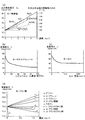
ここで、可変焦点レンズ3a,3bの印加電圧と曲率ディオプトリー(diopter=媒質の屈折率n/焦点距離f)との関係を図5(a)に、印加電圧と焦点距離fとの関係を図5(b)に例示する。これらの図に示すように、電圧を印加しないときや印加電圧が小さいときには、可変焦点レンズ3a,3bは負の屈折率を有する凹レンズとして機能する。一方、印加電圧が所定の電圧(図では約45V)より大きいときには、可変焦点レンズ3a,3bは正の屈折率を有する凸レンズとして機能する。
Here, the relationship between the applied voltage of the
以上の可変焦点レンズ3a,3bの焦点距離fa,fbは、以下の式(8),(9)のように算出される。
fa=fa1×fa2/(fa1+fa2) …(8)
fb=fb1×fb2/(fb1+fb2) …(9)
但し、下記の式(10),(11)に示すように、fa1,fb1は、透明板30a及び液体31aの部分の焦点距離であり、fa2,fb2は透明板30b及び液体31bの部分の焦点距離である。
fa1,fb1=fTa×fEa/(fTa+fEa) …(10)
fa2,fb2=fTb×fEb/(fTb+fEb) …(11)
The focal lengths f a and f b of the
f a = f a1 × f a2 / (f a1 + f a2 ) (8)
f b = f b1 × f b2 / (f b1 + f b2 ) (9)
However, as shown in the following formulas (10) and (11), f a1 and f b1 are focal lengths of the
f a1 , f b1 = f Ta × f Ea / (f Ta + f Ea ) (10)
f a2 , f b2 = f Tb × f Eb / (f Tb + f Eb ) (11)
なお、このような可変焦点レンズ3a,3bとしては、例えば「Fluid Focus Lens」(商品名:Royal Philips Electronics社製)等を用いることができるが、図6に示すような「PDN-1000 可変レンズユニット」(商品名:Varioptic社製)を用いることとしても良い。
また、可変焦点レンズ3a,3bは界面静電現象によって焦点距離を変化させることとして説明したが、他の原理や現象によって変化させることとしても良い。
As such
Further, although the variable
具体的には、例えば“Electrocapillarity and wetting of insulator films by water , C.R.Acad.Sci.Paris, t.137,p.157 (1993)”や特表2001−519539号公報などに開示のように、電気濡れ現象(エレクトロウェッティング)によって液体の接触角を調整し、光学面を変形させる結果、焦点距離を変化させることとしても良い。このような場合には、印加電圧がVのときの接触角を「cosθ(V)」、印加電圧が0のときの接触角を「cosθ(0)」とすると、印加電圧Vと接触角θとの関係は、概ね以下の式(12)のように示される(浅野浩一、“溶融炭酸塩形燃料電池における陽極反応場評価手法の開発−印加電圧による溶融炭酸塩の濡れメカニズムの検討−”[online]、(財)電力中央研究所、[平成16年9月30日検索]、インターネット<URL:http://ge-rd-info.denken.or.jp/ge_cgi-bin/rep_details.cgi?rep_num=W00022&host=>参照)。
cosθ(V)=cosθ(0)+(1/2)×(Cd/γLG)×V2 …(12)
(但し、Cd:電気二重層容量[μF/cm2]、γLG:気相−液相間の表面張力[N/m])
Specifically, for example, as disclosed in “Electrocapillarity and wetting of insulator films by water, CRAcad. Sci. Paris, t. 137, p. 157 (1993)” and Japanese translations of PCT publication No. 2001-515539. As a result of adjusting the contact angle of the liquid by a phenomenon (electrowetting) and deforming the optical surface, the focal length may be changed. In such a case, assuming that the contact angle when the applied voltage is V is “cos θ (V)” and the contact angle when the applied voltage is 0 is “cos θ (0)”, the applied voltage V and the contact angle θ The relationship is expressed by the following equation (12) (Koichi Asano, “Development of a method for evaluating the anode reaction field in molten carbonate fuel cells: Study of the mechanism of wetting of molten carbonate by applied voltage”) [Online], Central Research Institute of Electric Power, [searched on September 30, 2004], Internet <URL: http://ge-rd-info.denken.or.jp/ge_cgi-bin/rep_details.cgi see? rep_num = W00022 & host =>).
cos θ (V) = cos θ (0) + (1/2) × (Cd / γ LG ) × V 2 (12)
(However, Cd: Electric double layer capacity [μF / cm 2 ], γ LG : Surface tension between gas phase and liquid phase [N / m])
また、例えば特表平11−513129号公報や特表2001−519539号公報、特開2001−13306号公報に開示のように、液体の界面と内部とに生じる電気二重層の近傍の液体を電気泳動現象や電気浸透現象などの界面動電現象で流動させることによって接触角を調整し、光学面を変形させる結果、焦点距離を変化させることとしても良い。 Further, as disclosed in, for example, JP-A-11-513129, JP-A-2001-519539, and JP-A-2001-13306, the liquid in the vicinity of the electric double layer generated at the interface and inside of the liquid is electrically discharged. The focal length may be changed as a result of adjusting the contact angle by causing an electrokinetic phenomenon such as an electrophoretic phenomenon or an electroosmotic phenomenon to adjust the contact angle and deforming the optical surface.
また、例えば米国特許第3598479号明細書や米国特許第5138494号明細書、米国特許第5668620号明細書、実公昭40−28614号公報、実公昭51−49956号公報、特開昭55−36857号公報、特開平6−308303号公報、特開2002−311213号公報などに開示のように、膨張性の薄膜の間に液体を満たしたものを可変焦点レンズとして用い、液体の容積や圧力を調整することによって液面(光学面)を変形させる結果、焦点距離を変化させることとしても良い。 Further, for example, U.S. Pat. No. 3,598,479, U.S. Pat. No. 5,138,494, U.S. Pat. As disclosed in JP-A-6-308303, JP-A-2002-311213, etc., a liquid filled between inflatable thin films is used as a variable focus lens, and the volume and pressure of the liquid are adjusted. As a result of deforming the liquid surface (optical surface), the focal length may be changed.
また、例えば特開2000−81504号公報や特許第3400270号公報、特開2002−311213号公報、特開2003−14909号公報に開示のように、液体と密着した弾性膜に圧電素子や圧電アクチュエータ等で外圧を加えることによって光学面を変形させる結果、焦点距離を変化させることとしても良い。 Further, as disclosed in, for example, Japanese Patent Application Laid-Open Nos. 2000-81504, 3400220, 2002-31213, and 2003-14909, a piezoelectric element or a piezoelectric actuator is attached to an elastic film in close contact with a liquid. The focal length may be changed as a result of deforming the optical surface by applying an external pressure or the like.
また、「ハイブリッド配向液晶電気光学マイクロレンズにおける光学特性及び分子配向」(「光学」第20巻第4号(1991,4))や特許第3158016号公報に開示のように、透明な基板間の液晶分子の配向状態を電界によって変化させることにより焦点距離を変化させることとしても良い。 Further, as disclosed in “Optical Properties and Molecular Orientation in Hybrid Alignment Liquid Crystal Electro-Optical Microlens” (“Optics” Vol. 20, No. 4, (1991, 4)) and Japanese Patent No. 3158016, The focal length may be changed by changing the alignment state of the liquid crystal molecules by an electric field.
また、特開2002−243918号公報に開示のように、液体の表面(光学面)に密着する透明な基板を静電吸引力で変形することによって光学面を変形させる結果、焦点距離を変化させることとしても良い。 Further, as disclosed in Japanese Patent Laid-Open No. 2002-243918, as a result of deforming the optical surface by deforming a transparent substrate that is in close contact with the liquid surface (optical surface) with electrostatic attraction, the focal length is changed. It's also good.
また、図7に示すように、液体中に立設された管の内部の液体を可変光学素子として用い、管内部の毛細管または多孔性プラグの両端に電位差(流動電位)を生じさせることによって、管内の液面(光学面)の形状や高さを変化させる結果、焦点距離を変化させることとしても良い。 Further, as shown in FIG. 7, by using the liquid inside the tube erected in the liquid as a variable optical element, by generating a potential difference (flow potential) at both ends of the capillary or porous plug inside the tube, As a result of changing the shape and height of the liquid surface (optical surface) in the tube, the focal length may be changed.
また、図8に示すように、透明な浴槽内に立設された毛管内部の液体を可変光学素子として用い、浴槽内の液面に加わる圧力Fを調整することによって、毛管内部の液面(光学面)の形状や高さを変化させる結果、焦点距離を変化させることとしても良い。このような場合には、液面の表面張力を「γ」、圧力変化量を「ΔF」、液相と気相との密度差を「Δρ」、重力加速度を「g」、毛管の半径を「r」とし、図8に示すように角度θをおくと、毛管内部の液面の曲率Cと高さhとは以下の式(13),(14)のように示される。
C=2γ/ΔF(=2γ/Δρgh) …(13)
h=2γcosθ/Δρrg …(14)
Moreover, as shown in FIG. 8, by using the liquid inside the capillary standing up in the transparent bathtub as a variable optical element and adjusting the pressure F applied to the liquid level in the bathtub, the liquid level inside the capillary ( As a result of changing the shape and height of the optical surface), the focal length may be changed. In such a case, the surface tension of the liquid surface is “γ”, the pressure change amount is “ΔF”, the density difference between the liquid phase and the gas phase is “Δρ”, the gravitational acceleration is “g”, and the capillary radius is When “r” is set and the angle θ is set as shown in FIG. 8, the curvature C and the height h of the liquid level inside the capillary are expressed by the following equations (13) and (14).
C = 2γ / ΔF (= 2γ / Δρgh) (13)
h = 2γ cos θ / Δρ rg (14)
また、図9に示すように、Lippmannの電気毛管装置中の2種の液体を可変光学素子として用い、毛管内の界面(光学面)の高さや界面張力を電気毛管現象で変化させることによって光学面を変形させる結果、焦点距離を変化させることとしても良い。 In addition, as shown in FIG. 9, two types of liquids in Lippmann's electrocapillary device are used as variable optical elements, and the optical interface is changed by changing the height of the interface (optical surface) and the interfacial tension in the capillary by electrocapillarity. As a result of deforming the surface, the focal length may be changed.
剛体レンズ21は、図2に示すように、本実施の形態においては、凸レンズとなっており、ズームレンズユニット2の屈折力を正の側に偏らせている。また、この剛体レンズ21は、本発明における第2移動装置(図示せず)によって移動可能に設けられており、ズームレンズユニット2の光学特性を調整可能となっている。つまり、可変焦点レンズ3a,3bの光学特性の可変域に制限がある場合であっても、剛体レンズ21の位置調整によってズームレンズユニット2の屈折力を正または負の側に偏らせ、全体としての焦点距離やフォーカス位置が広い範囲で調整可能となっている。
As shown in FIG. 2, the
剛体レンズ21と可変焦点レンズ3bとの間には、絞り22が配設されている。
剛体レンズ21の下方には、シャッター23及び撮像素子24が配設されている。シャッター23は、後述のシャッターボタン41(図1参照)が押されると開状態となり、ズームレンズユニット2からの光を所定の時間だけ撮像素子24に当てるようになっている。撮像素子24は、例えばCCD等、受光量に応じてアナログ信号を生じるものである。
A
Below the
測光・測距センサ14は、被写体周辺の光量や色温度、カメラ1から被写体までの距離(以下、被写体距離とする)を測定するものであり、撮影用受光窓13に近接して設けられている。
The photometry / ranging
また、図1(b)に示すように、筐体10の裏面には表示部16が設けられている。
表示部16は、表示駆動部160(図2参照)によって駆動されて撮影画像や、操作者への操作案内などを表示するものである。この表示部16には、ズームレンズユニット2の設計パラメータの値や、ズームレンズユニット2の光学特性についてのシミュレーション演算の結果などが表示されるようになっている。
Further, as shown in FIG. 1B, a
The
表示部16の周辺には操作部4が配設されている。
操作部4は、操作者から操作指示が入力される複数のキーを備えており、本実施の形態においては、図1(a),(b)に示すように、電源のオン/オフを切り換えるための電源スイッチ40、シャッター23の開閉を指示するシャッターボタン41、各モードにおいて決定を指示する決定キー42、上下左右方向に選択操作を行うためのカーソルキー43、数値を入力するためのテンキー44、ズーム操作を指示するズームキー(図示せず)等を備えている。
An
The
これらのキーを介すことにより、操作部4にはズームレンズユニット2の可変設計パラメータの制御情報や、後述のプログラムメモリ66の内部の設計データについての選択指示などが入力されるようになっている。ここで、本実施の形態においては、可変設計パラメータとして、可変焦点レンズ3a,3bの光学面Sの曲率半径や位置、剛体レンズ21の位置などが用いられている。
Through these keys, control information for variable design parameters of the
また、図2に示すように、筐体10の内部には、制御装置5が配設されている。
制御装置5は、演算処理部50と撮影制御部51とを備えている。
Further, as shown in FIG. 2, a
The
演算処理部50は、図示しないCPUやROM,RAM等によって構成されている。この演算処理部50は、操作部4から送信される操作指示信号に基づいてカメラ1を撮影モードやレンズユニット設計モード、プログラム設計モード、再生モード等に切り換えるようになっている。
The
また、演算処理部50は、撮影モードにおいて、操作部4からの操作指示信号や、測光・測距センサ14による測定結果などに基づき、ズームレンズユニット2の焦点距離やフォーカス位置、撮影画像のホワイトバランス(WB)などの撮影条件を算出するようになっている。また、演算処理部50は、後述のプログラムメモリ66に記憶されたテーブルに基づいて、可変焦点レンズ3a,3bの電極34a,34bへの印加電圧を算出するようになっている。更に、演算処理部50は、温度センサ15による測定温度や、測光・測距センサ14による測定光量及び被写体距離、撮像素子からの電気信号から算出されるコントラストなどに基づいて、可変焦点レンズ3a,3bへの印加電圧の補正量を計算するようになっている。
Further, in the photographing mode, the
また、この演算処理部50は、操作部4から送信される指示情報に基づいて、ズームレンズユニット2の光学特性、本実施の形態においては、光路や収差、スポットダイアグラム、MTF(Modulation Transfer Function)特性などをシミュレーション演算によって求めるようになっている。また、演算処理部50は、収差やスポットダイアグラム、MTF特性について、所定の基準特性との比較によって評価を行うようになっている。なお、収差とは、本実施の形態においては、いわゆるザイデル(Seidel)の5収差や色収差などである。
Further, the
撮影制御部51は、後述の標準設計データ66aやカスタム設計データ66bに基づいて、ズームレンズユニット2の可変設計パラメータ、つまり可変焦点レンズ3a,3bの光学面Sの曲率半径や位置、剛体レンズ21の位置などを制御するようになっている。また、この撮影制御部51は、演算処理部50によって算出された撮影条件や補正量などに基づいて、ストロボ11や絞り22、可変焦点レンズ3a,3b等を制御するようになっている。
The
この撮影制御部51には、レンズ駆動部60a,60bや絞り駆動部61、シャッター駆動部62、タイミング制御部63、画像信号処理部65、ストロボ駆動部64等が接続されている。
The photographing
レンズ駆動部60a,60bは、可変焦点レンズ3a,3bの電極34a,34bに電圧を印加するものであり、印加電圧を調整できるようになっている。
絞り駆動部61は、絞り22の絞り量を調整するものである。
シャッター駆動部62は、操作部4のシャッターボタン41から送信される信号に基づいてシャッター23の開閉を制御するものである。
The
The
The
タイミング制御部63は、撮像素子24による撮影タイミングと同期して画像信号処理部65に信号処理を行わせるものである。
The
画像信号処理部65は、撮像素子24から送信されるアナログ信号にCDS(Correlated Double Sampling)処理や、AGC(Automatic Gain Control)処理、A/D変換処理などを施すものである。
ストロボ駆動部64は、ストロボ11を駆動して閃光を照射させるものである。
The image
The
以上の制御装置5には、上述の操作部4及び表示部16の他、プログラムメモリ66やメモリインターフェース67、内部メモリ68、画像処理部69、圧縮解凍部70、情報通信部72、電源制御部71等が接続されている。
The
プログラムメモリ66は、本発明における記憶部であり、ズームレンズユニット2の標準設計データ66a及びカスタム設計データ66bと、カメラ1の標準制御プログラム66c及びカスタム制御プログラム66dと、他機種ライブラリ66eとを記憶している。また、このプログラムメモリ66は、図5(b)に示すように、可変焦点レンズ3a,3bの焦点距離と、電極34a,34bへの印加電圧とを対応付け、テーブルとして記憶している。
The
ここで、標準設計データ66a及びカスタム設計データ66bは、本発明におけるパラメータ群として、可変焦点レンズ3a,3bの焦点距離や光学面Sの曲率、位置、剛体レンズ21の位置などのうち、少なくとも2つを除いた残りの可変設計パラメータの固定値の組合せについての情報を有している。なお、ここで除かれる2つ以上の可変設計パラメータ、例えば可変焦点レンズ3a,3bの各焦点距離などは、ズームレンズユニット2の合焦位置及び焦点距離を調整するために用いられる。
また、標準設計データ66aとは、製造メーカ等によって作成されたデフォルトの設計データであり、カスタム設計データ66bとは、操作者によって作成された設計データである。
Here, the standard design data 66a and the
The standard design data 66a is default design data created by a manufacturer or the like, and the
また、標準制御プログラム66c及びカスタム制御プログラム66dは、カメラ1の各部の動作や、前記組合せから除かれた2つ以上の可変設計パラメータ同士の関係式などについての情報を有している。また、標準制御プログラム66cとは、製造メーカ等によって作成されたデフォルトの制御プログラムであり、カスタム制御プログラム66dとは、操作者によって作成された制御プログラムである。
Further, the
また、他機種ライブラリ66eは、本発明における制御情報として、擬似化設計データ66f及び擬似化制御プログラム66gを備えている。これら擬似化設計データ66f,擬似化制御プログラム66gは、市販のズームレンズユニットや、市販のカメラ内部のズームレンズユニットの光学特性にズームレンズユニット2の光学特性を一致させるための設計データ,制御プログラムであり、ファイル名として市販のズームレンズユニットの名称や市販のカメラの名称が付されている。ここで、ズームレンズユニット2の光学特性とは、例えばズームレンズユニット2の収差特性と、スポットダイアグラム特性と、MTF特性と、焦点距離と、フォーカス位置などとの何れかについての値または範囲である。
The other model library 66e includes simulated design data 66f and a simulated control program 66g as control information in the present invention. The simulated design data 66f and the simulated control program 66g are designed data and a control program for matching the optical characteristics of the
メモリインターフェース(IF)67は、外部メモリ67aと内部メモリ68との間において、画像データや撮影条件などを送信可能にするものである。
The memory interface (IF) 67 enables transmission of image data, shooting conditions, and the like between the
内部メモリ68は、撮像素子24による撮影画像の画像データや、メモリインターフェース67を介して外部メモリ67aから入力された画像データ等を記憶するものである。また、この内部メモリ68は、可変焦点レンズ3a,3bの焦点距離などの撮影条件を画像データと対応付けて記憶するようになっている。
The
画像処理部69は、内部メモリ68の内部に記憶された画像データに対し、種々の画像処理を行うものである。
The
圧縮解凍部70は、撮像素子24による撮影画像の画像データを圧縮符号化したり、外部メモリ67aや内部メモリ68に記憶された画像データを解凍して復号化したりするものである。
The compression /
情報通信部72は、標準設計データ66aやカスタム設計データ66b、擬似化設計データ66f、標準制御プログラム66c、カスタム制御プログラム66d、擬似化制御プログラム66g等についての情報の送受信を行うものであり、外部機器で設計した設計データや制御プログラムをプログラムメモリ66に記憶させたり、プログラムメモリ66に記憶された設計データや制御プログラムを外部機器に送信し、他のカメラに使用させたりすることを可能としている。この情報通信部72は、無線通信部720及び入出力IF722を備えている。
The
無線通信部720はアンテナ721を介して外部機器(図示せず)との間で情報の送受信を無線方式で行うものであり、入出力IF722は外部機器(図示せず)との間で情報の送受信を有線方式で行うものである。
電源制御部71は、電池71aから制御装置5に電力を供給するものである。
The
The power
続いて、ズームレンズユニット2の動作について、図面を参照しながら説明する。
まず、図10に示すように、カメラ1の電源がオンになると、制御装置5は初期設定を行った後、プログラムメモリ66や前記外部機器から標準設計データ66a、カスタム設計データ66b、擬似化設計データ66f,標準制御プログラム66c,カスタム制御プログラム66d及び擬似化制御プログラム66gを読み出す。次に、制御装置5は、読み出した設計データ及び制御プログラムの内容またはファイル名を、例えば図11(a)〜(c)のような順序の操作案内によって表示部16に表示させる(ステップS1)。ここで、図11(c)に示すように、表示部16には擬似化設計データ66f及び擬似化制御プログラム66gの内容として既存のカメラや既存のズームレンズユニットの名称が表示されるので、これら擬似化設計データ66f及び擬似化制御プログラム66gの内容は容易かつ正確に把握可能となる。
Next, the operation of the
First, as shown in FIG. 10, when the power of the
なお、図11(c)では、擬似化制御プログラム66gの内容を擬似化されるカメラのメーカや製品名、仕様などによって表示しているが、図11(d)に示すように、擬似化されるカメラ内部のレンズユニットの製品名や仕様、光学特性、外観図、設計図、光跡図などによって表示することとしても良い。このような場合にも、擬似化設計データ66f及び擬似化制御プログラム66gの内容は容易かつ正確に把握可能となる。 In FIG. 11C, the contents of the simulation control program 66g are displayed according to the manufacturer, product name, specification, etc. of the camera to be simulated, but are simulated as shown in FIG. It may be displayed by the product name and specifications of the lens unit inside the camera, optical characteristics, external view, design drawing, light trace view, and the like. Even in such a case, the contents of the simulation design data 66f and the simulation control program 66g can be easily and accurately grasped.
次に、制御装置5は、表示されたカスタム設計データ66bが選択されたか否かを判別し(ステップS2)、カスタム設計データ66bが選択された場合(ステップS2;Yes)には、カスタム設計データ66bに基づいてズームレンズユニット2の可変設計パラメータを制御する(ステップS3)。
Next, the
次に、制御装置5は、カスタム制御プログラム66dが選択されたか否かを判別し(ステップS4)、カスタム制御プログラム66dが選択された場合(ステップS4;Yes)には、カスタム制御プログラム66dに基づいてカメラ1の各部を制御する(ステップS5)。
Next, the
一方、ステップS2においてカスタム設計データ66bが選択されなかった場合(ステップS2;No)には、制御装置5は擬似化設計データ66fが選択されたか否かを判別する(ステップS6)。
On the other hand, when the
このステップS6において擬似化設計データ66fが選択された場合(ステップS6;Yes)には、撮影制御部51は擬似化設計データ66fに基づいてズームレンズユニット2の可変設計パラメータを制御する(ステップS7)。これにより、プログラムメモリ66中の擬似化設計データ66fに基づいて、各可変設計パラメータの値は所定の状態、より詳細には、ズームレンズユニット2と既存のズームレンズユニットやカメラとが等しい光学特性を有する状態にされる。
If the simulated design data 66f is selected in step S6 (step S6; Yes), the
また、ステップS6において擬似化設計データ66fが選択されなかった場合(ステップS6;No)には、撮影制御部51は標準設計データ66aに基づいてズームレンズユニット2の可変設計パラメータを制御する(ステップS8)。
If the simulated design data 66f is not selected in step S6 (step S6; No), the
また、ステップS4においてカスタム制御プログラム66dが選択されなかった場合(ステップS4;No)には、制御装置5は、擬似化制御プログラム66gが選択されたか否かを判別する(ステップS9)。
When the
このステップS9において擬似化制御プログラム66gが選択された場合(ステップS9;Yes)には、制御装置5は擬似化制御プログラム66gに基づいてカメラ1の各部を制御する(ステップS10)。これにより、プログラムメモリ66中の擬似化制御プログラム66gに基づいて、カメラ1は既存のカメラと等しい光学特性を有する状態にされる。
When the simulation control program 66g is selected in step S9 (step S9; Yes), the
また、ステップS9において擬似化制御プログラム66gが選択されなかった場合(ステップS9;No)には、制御装置5は標準制御プログラム66cに基づいてカメラ1の各部を制御する(ステップS11)。
If the simulation control program 66g is not selected in step S9 (step S9; No), the
次に、図12,図13に示すように、制御装置5は、カメラ1のモードについての選択指示を表示部16に表示させ、レンズユニット設計モード、プログラム設計モード、プログラムデバッグモード、カスタム制御プログラム66dによる撮影モード(以下、カスタム撮影モードとする)、擬似化制御プログラム66gによる撮影モード(以下、他機種撮影モードとする)、標準制御プログラム66cによる撮影モード(以下、標準撮影モードとする)及び再生モードについて、操作者による選択の有無を順次判別する(ステップS12〜S18)。
Next, as shown in FIGS. 12 and 13, the
このステップS12においてレンズユニット設計モードが選択された場合(ステップS12;Yes)には、制御装置5はレンズユニット設計モード処理を行う(ステップS19)。
具体的には、図14に示すように、演算処理部50は、カスタム設計データを新たに設計するか否かについての選択指示を表示部16に表示させ、新規設計が選択されたか否かを判別する(ステップT1)。
When the lens unit design mode is selected in step S12 (step S12; Yes), the
Specifically, as shown in FIG. 14, the
このステップT1において新規設計が選択された場合(ステップT1;Yes)には、演算処理部50は、可変焦点レンズ3a,3bの曲率や位置、屈折率、剛体レンズ21の位置など、可変設計パラメータについての設計データの入力指示を表示部に表示させた後、操作部4から設計データの指示信号を受信する(ステップT2)。次に、演算処理部50は、必要な設計データが揃ったか否かを判別し(ステップT3)、設計データが揃っていない場合(ステップT3;No)には前記ステップT2の処理に戻り、揃っている場合(ステップT3;Yes)には後述のステップT5の処理を行う。ここで、ズームレンズユニット2に備えられた複数の可変焦点レンズ3a,3bの光学特性を調整することにより、従来と異なり、レンズを交換することなく広い範囲でズームレンズユニット2の光学特性が調整可能となる。また、設計データは可変設計パラメータについての固定値の情報を有するので、後述のステップT6,T8,T10.T12において具体的なシミュレーション演算を行うことが可能となる。
When a new design is selected in step T1 (step T1; Yes), the
一方、ステップT1において新規設計が選択されなかった場合(ステップT1;No)には、演算処理部50は、操作者によって指定された標準設計データ66aまたはカスタム設計データ66bをプログラムメモリ66から読み出す(ステップT4)。
On the other hand, when a new design is not selected in step T1 (step T1; No), the
次に、制御装置5は、得られた設計データに基づいて制御した場合のズームレンズユニット2における光路をシミュレーション演算によって求めるか否かについての選択指示を表示部16に表示させ、シミュレーション演算する選択がされたか否かを判別する(ステップT5)。
Next, the
このステップT5においてシミュレーション演算する選択がされなかった場合(ステップT5;No)には、演算処理部50は後述のステップT7の処理を行い、シミュレーション演算する選択がされた場合(ステップT5;Yes)には、演算処理部50は光線追跡のシミュレーション演算を行う(ステップT6)。
When the simulation calculation is not selected in step T5 (step T5; No), the
具体的には、図15に示すように、まず演算処理部50は設計データに基づいてズームレンズユニット2の設計図面を表示部16に表示させる(ステップU1)。
Specifically, as shown in FIG. 15, the
次に、演算処理部50は、ズームレンズユニット2における光学面の面番号jを1に設定する(ステップU2)。なお、以下の説明においては、便宜的にズームレンズユニット2の光学面の数をk個とする。
Next, the
次に、演算処理部50は、パラメータα1(=n1・u1)と、面番号1の光学面(以下、第1面とする)を光線が切る高さh1とを算出する(ステップU3)。ここで、図16に示すように、「n」は媒質の屈折率、「u」は入射光が光軸Lとなす角である。また、各記号の沿え字「j」や「j+1」は光学面の面番号を示す値である。
Next, the
次に、演算処理部50は、以下の式(20),(21)を用い、各光学面についてαj,hjを求め、プログラムメモリ66に記憶させる(ステップU4)。なお、式中、「r」は光学面の曲率半径、「d」は次の光学面までの光軸上での距離を示す。また、記号に「’」が付されている場合は光学面に対して像側(後側)のパラメータであることを示し、付されていない場合は物体側(前側)のパラメータであることを示す。
Next, the
α'j=αj+1=αj+hj・(n'j−nj)/rj …(20)
h'j=hj+1=hj−α'j・dj/n’j …(21)
α ′ j = α j + 1 = α j + h j · (n ′ j −n j ) / r j (20)
h ′ j = h j + 1 = h j −α ′ j · d j / n ′ j (21)
次に、演算処理部50は、面番号jの値がkであるか否かを判別し(ステップU5)、kでない場合(ステップU5;No)には面番号の値に1を加え(ステップU6)、ステップU4の処理に戻る。
Next, the
一方、ステップU5において面番号jがkである場合、つまり最終面についてαj,hjを求めた場合(ステップU5;Yes)には、以下の式(22)〜(24)から最終面についての角度u’k及び像点位置s’kと、ズームレンズユニット2の像側焦点距離f’とを求め、表示部16に表示させる(ステップU7)。また、このとき、演算処理部50は、公知の手法によりズームレンズユニット2の有効径や開口比、入射瞳、出射瞳などを求め、表示部16に表示させる。
On the other hand, when the surface number j is k in step U5, that is, when α j and h j are obtained for the final surface (step U5; Yes), the final surface is obtained from the following equations (22) to (24). Angle u ′ k and image point position s ′ k and the image side focal length f ′ of the
u’k=α’k/n’k …(22)
s’k=BF=hk/u’k …(23)
f’=h1/u’k …(24)
但し、式(23)中、「BF」はズームレンズユニット2のバックフォーカスである。
u ′ k = α ′ k / n ′ k (22)
s ′ k = BF = h k / u ′ k (23)
f ′ = h 1 / u ′ k (24)
However, in the formula (23), “BF” is the back focus of the
次に、演算処理部50は、ズームレンズユニット2の各面における高さhjの点を結ぶことによりズームレンズユニット2における光線追跡をシミュレーション演算し、シミュレーション演算の結果として光跡図を表示部16に表示させ(ステップU8)、光線追跡のシミュレーション演算を終了する。
Next, the
このように、ズームレンズユニット2の光線追跡のシミュレーション演算の結果が表示部16に表示されるので、高度な専門知識や豊富な経験の有無に関わらず、ズームレンズユニット2の設計内容が正確に評価可能となる。
As described above, since the result of the ray tracing simulation calculation of the
次に、図14に示すように、演算処理部50は、設計されたズームレンズユニット2における収差をシミュレーション演算によって求めるか否かについての選択指示を表示部16に表示させ、シミュレーション演算する選択がされたか否かを判別する(ステップT7)。
Next, as shown in FIG. 14, the
このステップT7において、シミュレーション演算する選択がされなかった場合(ステップT7;No)には、演算処理部50は後述のステップT9の処理を行い、シミュレーション演算する選択がされた場合(ステップT8;Yes)には、収差測定のシミュレーション演算を行う(ステップT8)。
In this step T7, when the simulation calculation is not selected (step T7; No), the
具体的には、図17に示すように、まず演算処理部50は、ズームレンズユニット2における光学面の面番号jを1に設定する(ステップU11)。
Specifically, as shown in FIG. 17, the
次に、演算処理部50は、近軸光線をズームレンズユニット2への入射光線として設定する(ステップU12)。このとき、演算処理部50は、例えばu1=1/a、h1=s1・u1、α1=n1・u1と設定して物体側主面の透過光線の高さhが1になるよう正規化することにより、焦点距離や口径の異なる光学系でも収差性能を比較できるようにする。なお、「a」は物点から物体側の主点までの距離である。また、この正規化は、焦点距離fを1としたり、撮像画角の対角長を1としたりすることにより行っても良い。
Next, the
次に、演算処理部50は、上述の式(20)〜(22)と以下の式(25),(26)とから各光学面についてα’j,h’j,s’jを求め、プログラムメモリ66に記憶させる(ステップU13)。
Next, the
s'j=hj/u'j=hj・n'j/α'j …(25)
sj+1=s'j−dj …(26)
s ′ j = h j / u ′ j = h j · n ′ j / α ′ j (25)
s j + 1 = s ′ j −d j (26)
次に、演算処理部50は、面番号jの値がkであるか否かを判別し(ステップU14)、kでない場合(ステップU14;No)には面番号の値に1を加え(ステップU15)、ステップU13の処理に戻る。これにより、物体側から像側に向かって、近軸光線の光線追跡が順次行われる。
Next, the
一方、ステップU14において面番号jがkである場合、つまり最終面についてα’j,h’j,s’jを求めた場合(ステップU14;Yes)には、演算処理部50は、ズームレンズユニット2における光学面の面番号jを再び1に設定する(ステップU16)。
On the other hand, when the surface number j is k in step U14, that is, when α ′ j , h ′ j , and s ′ j are obtained for the final surface (step U14; Yes), the
次に、演算処理部50は、軸外物点から入射瞳への主光線をズームレンズユニット2への入射光線として設定する(ステップU17)。このとき、演算処理部50は、例えばu1*=−a/a*、h1*=z*・u1*、α1*=n1・u1*と設定して物体側主点から物体高に対する角ωが(−1)になるよう正規化することにより、焦点距離や口径の異なる光学系でも収差性能を比較できるようにする。
Next, the
次に、演算処理部50は、以下の式(27)〜(30)から各光学面についてα’j *,h’j *,s’j *を求め、プログラムメモリ66に記憶させる(ステップU18)。
Next, the
α’j *=αj+1 *=αj *+hj *・(n’j−nj)/rj …(27)
h’j *=hj+1 *=hj *−α’j・dj/n’j …(28)
s'j *=hj */u'j *=hj *・n'j/α'j * …(29)
sj+1 *=s'j *−dj …(30)
α ′ j * = α j + 1 * = α j * + h j * · (n ′ j −n j ) / r j (27)
h ′ j * = h j + 1 * = h j * −α ′ j · d j / n ′ j (28)
s ′ j * = h j * / u ′ j * = h j * · n ′ j / α ′ j * (29)
s j + 1 * = s ′ j * −d j (30)
次に、演算処理部50は、面番号jの値がkであるか否かを判別し(ステップU19)、kでない場合(ステップU19;No)には面番号の値に1を加え(ステップU20)、ステップU18の処理に戻る。これにより、物体側から像側に向かって、前記主光線の光線追跡が順次行われる。
Next, the
一方、ステップU19において面番号jがkである場合、つまり最終面についてα’j *,h’j *,s’j *を求めた場合(ステップU19;Yes)には、図18に示すように、演算処理部50は、ズームレンズユニット2における光学面の面番号jを再び1に設定する(ステップU21)。
On the other hand, when the surface number j is k in step U19, that is, when α ′ j * , h ′ j * , and s ′ j * are obtained for the final surface (step U19; Yes), as shown in FIG. In addition, the
次に、演算処理部50は、図19(a)に示す式を用いて補助量Qj,Qj *,Δ(1/njsj),Δ(1/nj),Jjを計算し(ステップU22)、更に以下の式(31)〜(36)を用いて収差係数Ij〜Vj,Pjを計算する(ステップU23)。
Next, the
Ij=h4Q2・Δ(1/njsj) …(31)
IIj=Jj・Ij …(32)
IIIj=Jj・IIj …(33)
IVj=IIIj+Pj …(34)
Vj= Jj・IVj …(35)
Pj=-(1/rj)・Δ(1/nj) …(36)
I j = h 4 Q 2 · Δ (1 / n j s j ) (31)
II j = J j · I j (32)
III j = J j · II j (33)
IV j = III j + P j (34)
V j = J j · IV j (35)
P j =-(1 / r j ) · Δ (1 / n j ) (36)
次に、演算処理部50は、面番号jの値がkであるか否かを判別し(ステップU24)、kでない場合(ステップU24;No)には面番号の値に1を加え(ステップU25)、ステップU22の処理に戻る。これにより、物体側から像側に向かって、収差係数の計算が順次行われる。
Next, the
一方、ステップU24において面番号jがkである場合、つまり最終面についてIj〜Vj,Pjを求めた場合(ステップU24;Yes)には、演算処理部50は、図19(
b)に示すように、各面の収差係数をそれぞれ総和して各収差係数のザイデル和I〜V,Pを求める(ステップU26)。また、演算処理部50は、以下の式(37),(38)等から軸上色収差ΔS’及び倍率色収差ΔY’を求める。但し、式中、「νj」はAbb
e数(=(nd−1)/(nF−nc))であり、「nc」,「nd」,「nF」はC線、d線、F線の波長における屈折率である。
On the other hand, when the surface number j is k in step U24, that is, when I j to V j , P j are obtained for the final surface (step U24; Yes), the
As shown in b), the aberration coefficients of the respective surfaces are summed up to obtain the Seidel sums I to V and P of the respective aberration coefficients (step U26). Further, the
e number (= (n d −1) / (n F −n c )), where “n c ”, “n d ”, and “n F ” are refractive indices at wavelengths of C line, d line, and F line. It is.
ΔS’=−(1/α’k 2)・Σhj 2/(νj・fj) …(37)、
ΔY’=−(1/α’k)・Σhj 2・qj/(νj・fj) …(38)
ΔS ′ = − (1 / α ′ k 2 ) · Σh j 2 / (ν j · f j ) (37),
ΔY ′ = − (1 / α ′ k ) · Σh j 2 · q j / (ν j · f j ) (38)
次に、演算処理部50は、各収差係数、ザイデル和、軸上色収差及び倍率色収差を表示部16に表示させる(ステップU27)。また、演算処理部50は、計算結果に基づいてズームレンズユニット2の結像性能を評価し、この評価結果を表示部16に表示させる。これにより、操作者が結像性能を評価する場合と比較して、容易かつ正確にズームレンズユニット2の設計内容を評価することが可能となる。
Next, the
次に、演算処理部50は、収差曲線を表示させるか否かについての選択指示を表示部16に表示させ、表示させる選択がされたか否かを判別する(ステップU28)。そして、表示させる選択がされなかった場合(ステップU28;No)には、演算処理部50はそのまま収差測定のシミュレーション演算を終了する。
Next, the
一方、ステップU28において表示させる選択がされた場合(ステップU28;Yes)には、例えば以下の式(39),(40)などを用いてレンズ面または像高の高さ(角度)に対する各収差曲線を計算して表示部16に表示させ(ステップU29)、収差測定のシミュレーション演算を終了する。このように、ズームレンズユニット2の収差測定のシミュレーション演算の結果が表示部16に表示されるので、高度な専門知識や豊富な経験の有無に関わらず、ズームレンズユニット2の設計内容が正確に評価可能となる。
On the other hand, when the display is selected in step U28 (step U28; Yes), each aberration with respect to the lens surface or the height (angle) of the image height using, for example, the following expressions (39) and (40). A curve is calculated and displayed on the display unit 16 (step U29), and the aberration measurement simulation calculation is terminated. As described above, since the result of the simulation calculation of the aberration measurement of the
Δy=−(1/2α'k)[I・h3cosΦ−II・(n1・tanω)h2(2+cos2Φ)
+(3III+P)・(n1・tanω)2・h・cosΦ−V・(n1・tanω)3] …(39)
Δx=−(1/2α'k)[I・h3sinΦ−II・(n1・tanω)h2・sin2Φ)
+(III+P)・(n1・tanω)2・h・sinΦ] …(40)
Δy = − (1 / 2α'k) [I ・ h 3 cosΦ−II ・ (n1 ・ tanω)
+ (3III + P) ・ (n1 ・ tanω) 2・ h ・ cosΦ−V ・ (n1 ・ tanω) 3 ]… (39)
Δx = − (1 / 2α'k) [I ・ h 3 sinΦ−II ・ (n1 ・ tanω) h 2・ sin2Φ)
+ (III + P) ・ (n1 ・ tanω) 2・ h ・ sinΦ] (40)
次に、図14に示すように、制御装置5は、設計されたズームレンズユニット2のスポットダイアグラムをシミュレーション演算によって求めるか否かについての選択指示を表示部16に表示させ、シミュレーション演算する選択がされたか否かを判別する(ステップT9)。
Next, as shown in FIG. 14, the
シミュレーション演算する選択がされなかった場合(ステップT9;No)には、制御装置5は後述のステップT11の処理を行い、シミュレーション演算する選択がされた場合(ステップT9;Yes)には、演算処理部50はスポットダイアグラムの計算を行う(ステップT10)。
When the simulation calculation is not selected (step T9; No), the
具体的には、図20に示すように、まず演算処理部50は、前記ステップU1〜ステップU7と同様にして最終面の角度u’k,像点位置s’kや、ズームレンズユニット2の像側焦点距離f’、有効径、開口比、入射瞳、出射瞳などを求める(ステップU31)。
Specifically, as shown in FIG. 20, first, the
次に、演算処理部50は、操作者からの指示に基づいて、レンズ面または入射瞳面の分割数N×Nと、スポットダイアグラムの表示範囲(XY座標の範囲Xs,Ys)または表示スケール(倍率)との設定を行う(ステップU32,ステップU33)。
Next, based on an instruction from the operator, the
次に、演算処理部50は、入射光線の初期値と、最終面から焦点面までの距離dkまたは最終面の像点位置からのデフォーカス量(±dz)とを設定し(ステップU34,ステップU35)、光線の波長λを設定する(ステップU36)。ここで、入射光線の初期値とは、例えば物点位置d0や入射角、入射光線の初期単位ベクトルなどである。また、前記デフォーカス量とは、dk=BF±dzで表される値である。
Next, the
次に、図21に示すように、演算処理部50は、前記ステップU32,ステップU33で設定したxs及びNの値からdx=xs/Nを算出するとともに、変数xを0に設定する(ステップU37)。
次に、演算処理部50は、前記ステップU32,ステップU33で設定したys及びNの値からdy=ys/Nを算出するとともに、変数yを0に設定する(ステップU38)。
Next, as shown in FIG. 21, the
Next, the
次に、演算処理部50は、ズームレンズユニット2における光学面の面番号jを1に設定し(ステップU39)、光線と第1面との交点A1の座標を(x,y,0)に設定する(ステップU40)。
Next, the
次に、演算処理部50は、図22に示すように、(j−1)面の点Aj-1から出て(j)面の点Ajに入射する光線の単位ベクトルQj-1の方向余弦(Lj-1,Mj-1,Nj-1)や、(j−1)面と光軸との交点Sj-1から点Aj-1へのベクトルTj-1、(j)面の曲率cj、点Sjから単位ベクトルQj-1への垂線ベクトルWj、光軸の単位ベクトルk、(j)面の曲率半径r、ベクトルQj-1方向における点Qj-1から点Qjまでの距離qj-1、点Qj-1からQj-1及び垂線ベクトルWjの交点までの距離pj-1、ベクトルWjの方向成分Wxj,Wyj,Wzj等を以下の式(41)〜(44)に代入し、Pj-1,Wzj,Mj 2,qjを求める(ステップU41)。
Next, as shown in FIG. 22, the
Pj-1=−[xj-1Lj-1+yj-1Mj-1+(zj-1−dj-1)Nj-1] …(41)
Wzj=(zj-1−dj-1)+pj-1Nj-1 …(42)
Mj 2=−[x2 j-1+y2 j-1+(zj-1−dj-1)2−pj-1 2] …(43)
qj-1=pj-1+(cMj-1 2−2Wxj)/Nj-1[1+{1−(cj/Nj-1 2)(cjMj-1 2−2Wxj)}1/2] …(44)
P j−1 = − [x j−1 L j−1 + y j−1 M j−1 + (z j−1 −d j−1 ) N j−1 ] (41)
Wz j = (z j−1 −d j−1 ) + p j−1 N j−1 (42)
M j 2 = − [x 2 j−1 + y 2 j−1 + (z j−1 −d j−1 ) 2 −p j−1 2 ] (43)
q j−1 = p j−1 + (cM j−1 2 −2Wx j ) / N j−1 [1+ {1− (c j / N j−1 2 ) (c j M j−1 2 − 2Wx j )} 1/2 ] (44)
なお、これらの式(41)〜(44)は、以下の式(45)〜(48)から導入されるものである。
Tj-1+pj-1Qj-1=dj-1・k+Wj …(45)
Wj+(qj-1−pj-1)・Qj-1=Tj …(46)
Tj+r・Ej=r・k …(47)
nj・(Ej×Qj)=nj+1・(Ej×Qj+1) …(48)
These formulas (41) to (44) are introduced from the following formulas (45) to (48).
T j-1 + p j-1 Q j-1 = d j-1 · k + W j (45)
W j + (q j−1 −p j−1 ) · Q j−1 = T j (46)
T j + r · E j = r · k (47)
n j · (E j × Q j ) = n j + 1 · (E j × Q j + 1 ) (48)
次に、図21に示すように、演算処理部50は、以下の式(49)〜(51)を用い、光線と(j)面との交点Ajの座標(xj,yj,zj)を求める(ステップU42)。
Next, as shown in FIG. 21, the
xj=xj-1+qj-1L j-1 …(49)
yj=yj-1+q j-1M j-1 …(50)
zj=(zj-1−dj-1)+q j-1N j-1 …(51)
x j = x j-1 + q j-1 L j-1 (49)
y j = y j-1 + q j-1 M j-1 (50)
z j = (z j−1 −d j−1 ) + q j−1 N j−1 (51)
次に、演算処理部50は、点Ajで屈折して(j+1)面(図示せず)に入射する光線のベクトルQjの方向余弦(Lj,Mj,Nj)を以下の式(52)〜(54)から求めた後、上記と同様の手順により点Aj+1の座標(xj+1,yj+1,zj+1)を求める(ステップU43)。
Next, the
Lj=(n/n’)・L+g・ex …(52)
Mj=(n/n’)・M+g・ey …(53)
Nj=(n/n’)・N+g・ez …(54)
L j = (n / n ′) · L + g · ex (52)
M j = (n / n ′) · M + g · ey (53)
N j = (n / n ′) · N + g · ez (54)
また、演算処理部50は、A点における(j)面の法線ベクトルEjの方向余弦(exj,eyj,ezj)と、屈折率比(n/n')と、(j)面での入射角の余弦ζj及び出射角の余弦ζ’jと、係数gjとを以下の式(55)〜(58)から求める。
In addition, the
exj=−cxj、eyj=−cyj、ez=1−czj …(55)
(n/n’)=(nλ/n’λ)=(n’(j-1)λ/n’jλ) …(56)
ξ'j=[1−(n/n’)2・(1−ξj 2)]1/2 …(57)
gj=ξ'j−(n/n’)・ξj …(58)
e xj = −cx j , e yj = −cy j , e z = 1−cz j (55)
(N / n ′) = (nλ / n′λ) = (n ′ (j−1) λ / n ′ j λ) (56)
ξ ′ j = [1− (n / n ′) 2 · (1−ξ j 2 )] 1/2 (57)
g j = ξ ′ j − (n / n ′) · ξ j (58)
次に、演算処理部50は、面番号jの値がkであるか否かを判別し(ステップU44)、kでない場合(ステップU44;No)には面番号の値に1を加え(ステップU45)、ステップU41の処理に戻る。
Next, the
一方、ステップU44において面番号jがkである場合、つまり最終面についてベクトルQjの方向余弦(Lj,Mj,Nj)を求めた場合(ステップU44;Yes)には、演算処理部50は、例えば図23(a)〜(c)に示すように、光線と最終像面との交点(Δx,Δy)を、表示部16の表示範囲または表示スケールのXY座標上にプロットさ
せる(ステップU46)。
On the other hand, when the surface number j is k in step U44, that is, when the direction cosine (L j , M j , N j ) of the vector Q j is obtained for the final surface (step U44; Yes), the
次に、演算処理部50は、前記変数yの値がys以上であるか否かを判別し(ステップU47)、ys未満の場合(ステップU47;No)には変数yの値に1を加え(ステップU48)、ステップU39の処理に戻る。
Next, the
一方、ステップU47において変数yの値がys以上である場合、つまり、レンズ面または入射瞳面においてy軸方向に並ぶ微小エリアのそれぞれについての入射光の像点をプロットした場合(ステップU47;Yes)には、演算処理部50は、前記変数xの値がxs以上であるか否かを判別し(ステップU49)、xs未満の場合(ステップU49;No)には変数xの値に1を加え(ステップU50)、ステップU38の処理に戻る。
On the other hand, when the value of the variable y is greater than or equal to ys in step U47, that is, when the image points of incident light are plotted for each of the minute areas arranged in the y-axis direction on the lens surface or the entrance pupil plane (step U47; Yes). ), The
そして、変数xの値がxs以上である場合、つまり、レンズ面または入射瞳面においてx軸方向に並ぶ微小エリアのそれぞれについての入射光の像点をプロットした場合(ステップU49;Yes)には、演算処理部50は、得られたスポットダイアグラムに基づいてズームレンズユニット2の結像性能を評価し、この評価結果を表示部16に表示させてスポットダイアグラム測定のシミュレーション演算を終了する。このように、ズームレンズユニット2のスポットダイアグラム測定のシミュレーション演算の結果が表示部16に表示されるので、高度な専門知識や豊富な経験の有無に関わらず、ズームレンズユニット2の設計内容が正確に評価可能となる。また、演算処理部50による評価結果が示されるので、操作者が結像性能を評価する場合と比較して、容易かつ正確にズームレンズユニット2の設計内容を評価することが可能となる。
When the value of the variable x is greater than or equal to xs, that is, when the image points of incident light are plotted for each of the minute areas aligned in the x-axis direction on the lens surface or the entrance pupil plane (step U49; Yes). The
次に、図14に示すように、制御装置5は、設計されたズームレンズユニット2のMTF特性をシミュレーション演算によって求めるか否かについての選択指示を表示部16に表示させ、シミュレーション演算する選択がされたか否かを判別する(ステップT11)。
Next, as shown in FIG. 14, the
ステップT11において、シミュレーション演算する選択がされなかった場合(ステップT11;No)には、制御装置5は後述のステップT13の処理を行い、シミュレーション演算する選択がされた場合(ステップT11;Yes)には、演算処理部50はMTF特性の測定のシミュレーション演算を行う(ステップT12)。
In step T11, when the simulation calculation is not selected (step T11; No), the
具体的には、演算処理部50は、スポット密度の強度分布を像面の強度分布として用い、以下の式(59)または(60)からMTF値を|Rt(u)|または|Rs(u)|として計算し、空間周波数(u)やデフォーカス量(±dz)、像高、ズーム比などに対するMTFの変化として表示部16に表示させる。また、演算処理部50は、得られたMTF特性に基づいてズームレンズユニット2の結像性能を評価し、この評価結果を表示部16に表示させる。このように、ズームレンズユニット2のMTF値測定のシミュレーション演算の結果が表示部16に表示されるので、高度な専門知識や豊富な経験の有無に関わらず、ズームレンズユニット2の設計内容が正確に評価可能となる。また、演算処理部50による評価結果が示されるので、操作者が結像性能を評価する場合と比較して、容易かつ正確にズームレンズユニット2の設計内容を評価することが可能となる。
Specifically, the
|Rt(u)|={A(u)2+B(u)2}1/2 …(59)
|Rs(u)|=(1/N)Σicos(2πu・Δxi) …(60)
但し、式中、Δxi,Δyiはスポット座標であり、A(u),B(u)は、A(u)
=(1/N)Σicos(2πu・Δyi),B(u)=(1/N)Σisin(2πu・Δy
i)で示される値である。
| Rt (u) | = {A (u) 2 + B (u) 2 } 1/2 (59)
| Rs (u) | = (1 / N) Σ i cos (2πu · Δx i ) (60)
In the equation, Δx i and Δy i are spot coordinates, and A (u) and B (u) are A (u).
= (1 / N) Σ i cos (2πu · Δyi), B (u) = (1 / N) Σ i sin (2πu · Δy
i ) is the value indicated.
なお、演算処理部50は、基本周波数をu0=1/p[line pair/mm](pは基本周期)とし、周波数u=m/p=mu0(mは正の整数)の格子の強度分布I(x)を以下の式(61),(62)のようにフーリエ変換することにより、MTFの値を振幅Cmとして求めることとしても良いし、いわゆるスリット法やコントラスト法を模擬的に行ったり、点像分布関数(PSF)や線像分布関数(LSF)をフーリエ変換したりすることによってMTF値を求めることとしても良い。
The
I(x)=ΣCm・exp(−i・2π・mu0x)、 ・・・・(61)
Cm=∫I(x)exp(i・2π・mu0x)dx、 ・・・・(62)
I (x) = ΣCm · exp (−i · 2π · mu 0 x), (61)
Cm = ∫I (x) exp (i · 2π · mu 0 x) dx, (62)
次に、制御装置5は、設計データをプログラムメモリ66に記憶させるか否かについての選択指示を表示部16に表示させ、記憶させる選択がされたか否かを判別する(ステップT13)。
Next, the
ステップT13において、記憶させる選択がされなかった場合(ステップT13;No)には、制御装置5は、レンズユニット設計モード処理を終了する。
一方、ステップT13において記憶させる選択がされた場合(ステップT13;Yes)には、制御装置5は、設計データにファイル名を付けてプログラムメモリ66に記憶させ(ステップT14)、レンズユニット設計モード処理を終了する。このとき、上述のステップT6,T8,T10,T12でシミュレーション演算を行っている場合には、制御装置5は、シミュレーション演算の結果も併せてプログラムメモリ66に記憶させる。
In step T13, when the selection to memorize | store is not made (step T13; No), the
On the other hand, when selection is made to store in step T13 (step T13; Yes), the
そして、図12に示すように、制御装置5は、操作部4からの指示信号に基づいて各種の処理を行い(ステップS20)、処理を終了する。なお、制御装置5は、このときの指示信号に基づいてカメラ1を後述のプログラム設計モードや撮影モードに移行させることとしても良い。
And as shown in FIG. 12, the
また、上述のステップS12においてレンズユニット設計モードが選択されず(ステップS12;No)、ステップS13においてプログラム設計モードが選択された場合(ステップS13;Yes)には、制御装置5は、プログラム設計モード処理を行う。
If the lens unit design mode is not selected in step S12 described above (step S12; No) and the program design mode is selected in step S13 (step S13; Yes), the
具体的には、まず制御装置5は、操作部4を介して入力されたカスタム制御プログラム66dを受信する(ステップS21)。次に、制御装置5は、カスタム制御プログラム66dの設計が終了したか否かを判別し(ステップS22)、終了していない場合(ステップS22;No)には上記ステップS21の処理に戻り、終了している場合(ステップS22;Yes)には、設計されたカスタム制御プログラムにファイル名を付けてプログラムメモリ66に記憶させ(ステップS23)、プログラム設計モード処理を終了する。
Specifically, first, the
そして、制御装置5は、操作部4からの指示信号に基づいて各種の処理を行い(ステップS20)、処理を終了する。
And the
また、上述のステップS13においてプログラム設計モードが選択されず(ステップS13;No)、ステップS14においてプログラムデバッグモードが選択された場合(ステップS14;Yes)には、制御装置5は、プログラムデバッグモード処理を行う。
If the program design mode is not selected in step S13 described above (step S13; No) and the program debug mode is selected in step S14 (step S14; Yes), the
具体的には、まず制御装置5は、指定されている制御プログラム及び設計データを読み込む(ステップS24)。そして、制御装置5は、読み込んだ制御プログラムを実行し(ステップS25)、実行結果を表示部16に表示させるとともにプログラムメモリ66に記憶させ(ステップS26)、プログラムデバッグモード処理を終了する。
Specifically, the
そして、制御装置5は、操作部4からの指示信号に基づいて各種の処理を行い(ステップS20)、処理を終了する。
And the
また、上述のステップS14においてプログラムデバッグモードが選択されず(ステップS14;No)、ステップS15においてカスタム撮影モードが選択された場合(ステップS15;Yes)には、制御装置5は、カスタム制御プログラム66dに基づいてカスタム撮影モード処理を行う。
If the program debug mode is not selected in step S14 described above (step S14; No) and the custom shooting mode is selected in step S15 (step S15; Yes), the
具体的には、制御装置5は、選択されたカスタム設計データ66bに基づいてズームレンズユニット2の可変設計パラメータを設定し(ステップS27)、更に、選択されたカスタム制御プログラム66dに基づいてカメラ1の各部を制御する
(ステップS28)。そして、この状態において、操作者からの指示に応じて撮影を行い、カスタム撮影モードを終了する。
Specifically, the
そして、制御装置5は、操作部4からの指示信号に基づいて各種の処理を行い(ステップS20)、処理を終了する。
And the
また、上述のステップS15においてカスタム撮影モードが選択されず(ステップS15;No)、ステップS17において他機種撮影モードが選択された場合(ステップS17;Yes)には、制御装置5は、擬似化制御プログラム66gに基づいてカスタム撮影モード処理を行う。
If the custom shooting mode is not selected in step S15 described above (step S15; No) and the other model shooting mode is selected in step S17 (step S17; Yes), the
具体的には、制御装置5は、選択された擬似化設計データ66fに基づいてズームレンズユニット2の可変設計パラメータを設定し(ステップS29)、更に、選択された擬似化制御プログラム66gに基づいてカメラ1の各部を制御する(ステップS30)。そして、この状態において、操作者からの指示に応じて撮影を行い、カスタム撮影モードを終了する。
Specifically, the
そして、制御装置5は、操作部4からの指示信号に基づいて各種の処理を行い(ステップS20)、処理を終了する。
And the
また、上述のステップS16において他機種撮影モードが選択されず(ステップS16;No)、ステップS17において標準撮影モードが選択された場合(ステップS17;Yes)には、制御装置5は、標準制御プログラムに基づいて標準撮影モード処理を行う。
If the other model shooting mode is not selected in step S16 described above (step S16; No) and the standard shooting mode is selected in step S17 (step S17; Yes), the
具体的には、まず演算処理部50は、可変焦点レンズ3a,3bの焦点距離を初期設定値に設定する。ここで、操作者がカメラ1を被写体に向けると、被写体からの光線がズームレンズユニット2に入射する。このとき、プリズム20が可変焦点レンズ3a,3bの上方に配設されているので、水平に配設された可変焦点レンズ3a,3bに対し、横方向からの光線が案内される。また、可変焦点レンズ3a,3bが水平に配設されているので、液体31a,31bが安定な状態で維持される結果、振動や重力、加速度などの影響による液体31a,31bの流動や、光学面Sの変形が防止される。また、可変焦点レンズ3a,3bが縦に配設された場合と比較して、前記光学面Sの面積が広くなる、つまり、可変焦点レンズ3a,3bのFナンバーが小さくなるため、像の明るさを向上させることが可能となる。
Specifically, the
次に、制御装置5は、操作部4からの操作指示信号に基づいてシャッタースピードや絞り量などの撮影条件を設定する(ステップS31)。
次に、演算処理部50が温度センサ15による測定温度や、測光・測距センサ14による測定光量及び被写体距離、撮像素子からの電気信号から算出されるコントラストなどに基づいて、可変焦点レンズ3a,3bへの印加電圧の補正量を計算し、この補正量に基づいて撮影制御部51が可変焦点レンズ3a,3bに電圧を印加する。また、撮影制御部51は、操作部4からの指示信号などに基づいてストロボ11に対してホワイトバランス(WB)処理を行う(ステップS32)。
Next, the
Next, based on the temperature measured by the
次に、制御装置5は、ズームレンズユニット2のズーム処理及びAF処理を行い(ステップS33)、所定時間内にシャッターボタン41が押されたか否かを判別する(ステップS34)。
このステップS34においてシャッターボタン41が押された場合(ステップS34;Yes)には、制御装置5はシャッター駆動部62やストロボ11などを制御して被写体画像を撮影する(ステップS35)。撮影を行ったら、制御装置5は画像データを圧縮解凍部70に圧縮符号化させた後、可変焦点レンズ3a,3bの焦点距離や倍率などとともに内部メモリ68に記憶させる(ステップS36)。そして、操作部からの信号に基づいて処理を行った後、標準撮影モードを終了する。
Next, the
When the
一方、ステップS34において所定の時間内にシャッターボタン41が押されていない場合や、撮影条件の変更が指示された場合(ステップS34;No)には、操作部からの信号に基づいて処理を行った後、制御装置5はそのまま標準撮影モードを終了する。
On the other hand, when the
そして、制御装置5は、操作部4からの指示信号に基づいて各種の処理を行い(ステップS20)、処理を終了する。
And the
また、上述のステップS17において標準撮影モードが選択されず(ステップS17;No)、ステップS18において再生モードが選択された場合(ステップS18;Yes)には、制御装置5は、図13に示すように、再生モード処理を行う。
If the standard shooting mode is not selected in step S17 described above (step S17; No) and the playback mode is selected in step S18 (step S18; Yes), the
具体的には、まず制御装置5は、操作者からの指示に従って内部メモリ68または外部メモリ67a中の画像データを選択し(ステップS37)、この画像データを表示部16に表示させるか、或いは外部メモリ67aに出力し(ステップS38)、再生モード処理を終了する。
Specifically, first, the
そして、制御装置5は、操作部4からの指示信号に基づいて各種の処理を行い(ステップS20)、処理を終了する。
And the
また、上述のステップS17において再生モードが選択されなかった場合(ステップS17;No)には、制御装置5は、プログラム設定モード処理を行う(ステップS39)。
When the reproduction mode is not selected in step S17 described above (step S17; No), the
具体的には、図24に示すように、まず制御装置5は、プログラムメモリ66に記憶させたカスタム制御プログラム66dを利用するか否かについての選択指示を表示部16に表示させ、利用する選択がされたか否かを判別する(ステップT20)。
Specifically, as shown in FIG. 24, first, the
このステップT20において利用する選択がされた場合(ステップT20;Yes)には、制御装置5は、操作者によって選択されたカスタム制御プログラム66dをプログラムメモリ66から読み出し、このカスタム制御プログラム66dを制御用のプログラムとして設定する(ステップT21)。
When selection to use is made in step T20 (step T20; Yes), the
次に、制御装置5は、選択されたカスタム制御プログラム66dに対応する標準設計データ66a及びカスタム設計データ66bのうち、操作者によって選択された設計データをプログラムメモリ66から読み出し、この設計データを制御用のデータとして設定する(ステップT22)。
Next, the
そして、制御装置5は、カメラ1の各部の機能や設定条件などを設定して(ステップT23)、プログラム設定モード処理を終了する。
And the
一方、前記ステップT20において、カスタム制御プログラム66dを利用する選択がされなかった場合(ステップT20;No)には、制御装置5は、擬似化制御プログラム66gを利用するか否かについての選択指示を表示部16に表示させ、利用する選択がされたか否かを判別する(ステップT24)。
On the other hand, when the selection using the
このステップT24において利用する選択がされた場合(ステップT24;Yes)には、制御装置5は、上述の図11(a)〜(c)のような操作案内を表示部16に順次表示させることにより、操作者に擬似化制御プログラム66g及び擬似化設計データ66fを選択させた後、選択された擬似化制御プログラム66gをプログラムメモリ66から読み出し、この擬似化制御プログラム66gを制御用のプログラムとして設定する(ステップT25)。
When the selection to use is made in step T24 (step T24; Yes), the
次に、制御装置5は、選択された擬似化制御プログラム66gに対応する擬似化設計データ66fのうち、操作者によって選択された擬似化設計データ66fをプログラムメモリ66から読み出し、この擬似化設計データ66fを制御用のデータとして設定する(ステップT26)。
Next, the
そして、制御装置5は、カメラ1の各部の機能や設定条件などを設定して(ステップT23)、プログラム設定モード処理を終了する。
And the
一方、前記ステップT24において、擬似化制御プログラム66gを利用する選択がされなかった場合(ステップT24;No)には、制御装置5は、選択された標準制御プログラム66c,標準設計データ66aを制御用のプログラム,データとして設定する(ステップT27,T28)。
そして、制御装置5は、カメラ1の各部の機能や設定条件などを設定して(ステップT23)、プログラム設定モード処理を終了する。
On the other hand, when the use of the simulation control program 66g is not selected in step T24 (step T24; No), the
And the
そして、制御装置5は、操作部4からの指示信号に基づいて各種の処理を行い(ステップS20)、処理を終了する。
And the
以上のカメラ1によれば、プログラムメモリ66中の擬似化設計データ66fに基づいて、各可変設計パラメータの値を既存のレンズユニットと等しい光学特性を有する状態にすることができるので、操作者が自分で光学ユニットを設計する必要がない。従って、従来と異なり、操作者は高度な専門知識や豊富な経験の有無に関わらず、ズームレンズユニット2について所望の光学特性を容易に得ることができる。
According to the
また、擬似化設計データ66f及び擬似化制御プログラム66gの内容を容易かつ正確に把握することができるため、ズームレンズユニット2について所望の光学特性をいっそう容易に得ることができる。
Further, since the contents of the simulated design data 66f and the simulated control program 66g can be easily and accurately grasped, desired optical characteristics can be obtained more easily for the
なお、上記の実施の形態においては、ズームレンズユニット2は光軸Lに沿ってプリズム20、可変焦点レンズ3a,3b、剛体レンズ21をこの順序で備えることとして説明したが、例えば図25に示すように、他の順序で備えることとしても良い。
In the above embodiment, the
また、可変焦点レンズ3a,3bは剛体レンズ21よりも物体側に配置されていることとして説明したが、像側に配置されていることとしても良い。
Although the
また、剛体レンズ21を単レンズとして説明したが、図26に示すように、複数枚のレンズからなるレンズユニットとしても良い。このような場合におけるズームレンズユニットは、例えば図27(a),(b)に示すような設計データに基づいて形成することができる。この場合の収差曲線を図27(c),(d)に、収差係数などの値を図28に例示する。ここで、図27(b)中、「液面の位置」とは、図26に示すように、透明板30a,30bから、界面の中心までの距離である。また、図27(c)は倍率m=0.6、焦点距離f=15mmのときの縦収差図であり、図27(d)は倍率m=0.6、焦点距離f=15mm、入射角5°のときの横収差図である。また、図27(c)、(d)中、「C線」とは波長656.27nmの光、「d線」とは波長587.56nmの光、「F線」とは波長486.13nmの光である。
Further, the
また、撮影用受光窓13から入射した光をプリズム20によって屈折させることとして説明したが、マンジャン(Mangin)鏡などのミラーによって屈折させることとしても良い。
Further, the light incident from the photographing
また、ズームレンズユニット2のプリズム20、可変焦点レンズ3a,3b及び剛体レンズ21は上下方向に配列されていることとして説明したが、横方向に配列されることとしても良い。
Moreover, although the
また、可変焦点レンズ3a,3bは固定されていることとして説明したが、ラックやピニオン等によって移動可能としても良い。この場合には、可変焦点レンズ3a,3bの位置を調整することによってもズームレンズユニット2の光学特性を調整することができるため、より容易に所望の光学特性を得ることができる。また、可変焦点レンズ3a、3bの光学特性の可変域に制限がある場合であっても、位置調整によってズームレンズユニット2の屈折力を正または負の側に偏らせ、全体としての焦点距離やフォーカス位置を広い範囲で調整することができる。
Although the
また、可変焦点レンズ3a,3bは、光学面Sを変形させることにより屈折力などを変化させることとして説明したが、液体31a,31bを屈折率の異なる他の液体と入れ換えることにより変化させることとしても良い。
The
また、演算処理部50は、MTF特性をシミュレーション演算によって求めることによりズームレンズユニット2の結像性能を評価することとして説明したが、OTF(Optical Transfer Function)特性やPTF(Phase Transfer Function)特性をシミュレーション演算によって求めることにより評価することとしても良いし、MTF値やOTF値を平面収差の評価データなどに変換して評価したり、いわゆるニトカ法(Nitka method)やRudinger & Spiegler法、解像力法などによって評価したりすることとしても良い。
In addition, the
また、本発明に係る光学ユニットをズームレンズユニット2として説明したが、1つの可変設計パラメータのみを可変とし、残りを固定とすることにより、固定焦点のレンズユニットとしても良い。このような場合には、光学ユニットがズームレンズユニットとして機能する場合と比較して、光学特性を高めることができるとともに制御を容易化することができる。
Although the optical unit according to the present invention has been described as the
また、本発明に係る光学ユニットがカメラ1に備えられることとして説明したが、望遠鏡や顕微鏡、双眼鏡に備えられることとしても良い。
Moreover, although the optical unit according to the present invention has been described as being provided in the
<実施の形態の変形例>
次に、本発明の実施の形態の変形例について説明する。なお、上記実施の形態と同様の構成要素には同一の符号を付し、その説明を省略する。
<Modification of Embodiment>
Next, a modification of the embodiment of the present invention will be described. In addition, the same code | symbol is attached | subjected to the component similar to the said embodiment, and the description is abbreviate | omitted.
本変形例におけるカメラ1の演算処理部50Aは、図29,図30に示すように、前記実施の形態における演算処理部50とは異なるレンズユニット設計モード処理を行うようになっている。
具体的には、まず演算処理部50Aは、図31(a)〜(c)に示すような操作案内を表示部16に表示させることによって操作者に設計データを選択させ、選択された標準設計データ66a、カスタム設計データ66bまたは擬似化設計データ66fをプログラムメモリ66から読み込む(ステップT50)。なお、図31(a)〜(c)では、カスタム設計データ66bのうち「カスタム2」のファイル名の設計データが読み込まれている。
As shown in FIGS. 29 and 30, the
Specifically, first, the
次に、演算処理部50Aは、操作部4を介して設計データの修正または編集指示を受信する(ステップT51)。
次に、演算処理部50Aは、前記ステップT6,T8,T10と同様にして光線追跡,収差測定,スポットダイアグラム測定のシミュレーション演算を行い、図31(d)に示すように、シミュレーション演算の結果を表示部16に表示させる(ステップT52〜T54)。なお、このとき、演算処理部50Aは、MTF特性など、他の光学特性の測定のシミュレーション演算を行い、そのシミュレーション演算の結果を表示させることとしても良い。
Next, the
Next, the
次に、演算処理部50Aは、図30に示すように、操作部4を介して操作者による所望の光学特性の指示を受信する(ステップT55)。ここで、操作者から操作部4に入力される指示としては、図31(e)〜(h)に示すように、球面収差の許容量を±0.001未満とする指示や、球面収差を所定量だけ残すようにしてズームレンズユニット2を軟焦点撮影用のソフトフォーカスレンズユニットとする指示、球面収差の補正量を増減する指示などがある。
Next, as shown in FIG. 30, the
次に、演算処理部50Aは、操作者によって選択または入力された光学特性にズームレンズユニット2の光学特性を近づけるよう、設計データの一部を修正する(ステップT56)。
Next, the
次に、演算処理部50Aは、設計データを修正した後のズームレンズユニット2に対し、前記ステップT6,T8,T10と同様にして光線追跡,収差測定,スポットダイアグラム測定のシミュレーション演算を行い、シミュレーション演算の結果を表示部16に表示させる(ステップT57〜T59)。なお、このとき、演算処理部50Aは、MTF特性など、他の光学特性の測定のシミュレーション演算を行い、そのシミュレーション演算の結果を表示させることとしても良い。
Next, the
次に、演算処理部50Aは、操作者に所望の光学特性に関する光学特性情報を選択または入力させ、この光学特性情報で指示される光学特性と、設計データの修正後のズームレンズユニット2の光学特性とが近似しているか否かを判別する(ステップT60)。
Next, the
このステップT60において光学特性が近似していない場合(ステップT60;No)には、演算処理部50Aは、ステップT60の判別を所定の回数以上したか否かを判別し(ステップT61)、所定の回数未満である場合(ステップT61;No)には前記ステップT56の処理に戻る。また、このステップT65において所定の回数以上である場合(ステップT61;Yes)には、演算処理部50Aは、操作者の所望の光学特性が得られない旨を表示部16に表示させ(ステップT62)、後述のステップT64の処理を行う。
If the optical characteristics are not approximated in step T60 (step T60; No), the
一方、前記ステップT60において光学特性が近似している場合、つまり、操作者の所望の光学特性が満足された場合(ステップT60;Yes)には、演算処理部50Aは、その旨を表示部16に表示させる(ステップT63)。
On the other hand, when the optical characteristics are approximate in step T60, that is, when the optical characteristics desired by the operator are satisfied (step T60; Yes), the
次に、演算処理部50Aは、ズームレンズユニット2を再設計するか否かについての選択指示を表示部16に表示させ、再設計が選択されたか否かを判別する(ステップT64)。
Next, the
このステップT64において再設計が選択された場合(ステップT64;Yes)には、演算処理部50Aは前記ステップT55の処理に戻る。一方、再設計が選択されなかった場合(ステップT64;No)には、演算処理部50Aは、設計データをプログラムメモリ66に記憶させるか否かについての選択指示を表示部16に表示させる(ステップT65)。
When redesign is selected in step T64 (step T64; Yes), the
このステップT65において記憶させる選択がされなかった場合(ステップT65;No)には、演算処理部50Aはそのままレンズユニット設計モード処理を終了し、記憶させる選択がされた場合(ステップT65;Yes)には、設計データ及びシミュレーション演算の結果にファイル名を付けてプログラムメモリ66に記憶させ(ステップT66)、レンズユニット設計モード処理を終了する。
If the selection to be stored is not made in step T65 (step T65; No), the
このようなカメラ1によれば、操作者の所望の光学特性にズームレンズユニット2の光学特性を近づけるよう設計データの一部を修正するので、ズームレンズユニット2について、所望の光学特性を確実に得ることができる。
According to such a
1 カメラ
2 ズームレンズユニット(光学ユニット)
3a〜3h 可変焦点レンズ(特性可変レンズ)
5 制御装置
4 操作部
16 表示部
20 プリズム
21 剛体レンズ
24 撮像素子
30a,30b 透明板
31a,31b 液体
65 画像信号処理部
66 プログラムメモリ(記憶部)
72 情報通信部
S 光学面
1
3a-3h Variable focus lens (variable lens)
DESCRIPTION OF
72 Information Communication Unit S Optical Surface
Claims (26)
前記レンズユニットの光軸上に配置された複数の特性可変光学素子であって、各々の特性可変光学素子が単体で光学特性を変化させることが可能な複数の特性可変光学素子と、
前記レンズユニット内における前記複数の特性可変光学素子の各々の光学特性を電子制御によって変化させることで、前記レンズユニット全体の光学特性を変化させる電子制御手段と、
前記レンズユニット全体における所定の光学特性が、前記電子制御手段によって変化させることの可能な全範囲の中で所定の範囲内に収まるように、前記複数の特性可変光学素子の各々の光学特性を制御するための制御情報を記憶する記憶手段と、
ユーザーの指示操作に応じて、前記記憶手段に記憶された制御情報の編集または新たな作成を行う編集手段と、
撮影時において、前記複数の特性可変光学素子の各々の光学特性を、前記編集手段により作成または編集が行われた制御情報に基づいて前記電子制御手段に制御させる撮影制御手段と、
を備えたことを特徴とするカメラ。 A camera equipped with a lens unit capable of programming optical characteristics,
A plurality of variable characteristic optical elements disposed on the optical axis of the lens unit , each variable characteristic optical element being capable of changing the optical characteristic by itself ,
Electronic control means for changing the optical characteristics of the entire lens unit by changing the optical characteristics of each of the plurality of variable characteristic optical elements in the lens unit by electronic control;
The optical characteristics of each of the plurality of characteristic variable optical elements are controlled so that the predetermined optical characteristics of the entire lens unit fall within a predetermined range within the entire range that can be changed by the electronic control unit. Storage means for storing control information for
Editing means for editing or newly creating control information stored in the storage means in response to a user instruction operation;
An imaging control unit that causes the electronic control unit to control the optical characteristics of each of the plurality of variable characteristic optical elements based on control information created or edited by the editing unit during imaging,
A camera characterized by comprising
ユーザーによる指示操作に応じて、前記記憶手段に記憶された複数の制御情報の中から、撮影時において前記複数の特性可変光学素子の各々の光学特性を制御するための制御情報を選択する選択手段を更に備えたことを特徴とする請求項1または2記載のカメラ。 Selection means for selecting control information for controlling the optical characteristics of each of the plurality of characteristic variable optical elements at the time of photographing from a plurality of control information stored in the storage means in response to an instruction operation by a user The camera according to claim 1, further comprising:
前記選択手段は、前記記憶手段に記憶された複数の制御情報の各々に対応した光学特性に関する情報を選択候補として表示し、この表示された選択候補の中から1つの光学特性に関する情報をユーザーに選択させることにより対応する制御情報を選択することを特徴とする請求項3記載のカメラ。 The storage means stores the control information and information related to optical characteristics corresponding to the control information in association with each other,
The selection means displays information on optical characteristics corresponding to each of the plurality of control information stored in the storage means as selection candidates, and information on one optical characteristic from the displayed selection candidates is displayed to the user. 4. The camera according to claim 3 , wherein the corresponding control information is selected by the selection.
前記選択手段は、前記レンズユニットの設計図、断面図、光跡図、のうちの1または複数の画像情報を選択候補として表示することを特徴とする請求項5記載のカメラ。 The storage means stores one or more pieces of information of a design drawing, a sectional view, and a light trace of the lens unit as information on the optical characteristics,
The camera according to claim 5, wherein the selection unit displays one or a plurality of pieces of image information of a design drawing, a sectional view, and a light trace of the lens unit as selection candidates.
前記選択手段は、前記既存のレンズユニットまたは前記既存のカメラを特定することが可能な情報を選択候補として表示し、この表示された選択候補の中から1つの前記既存のレンズユニットまたは前記既存のカメラの情報をユーザーに選択させることにより対応する制御情報を選択することを特徴とする請求項5記載のカメラ。 The storage means includes control information for causing the lens unit included in the camera to simulate optical characteristics of the existing lens unit or the existing camera, and the existing lens unit or the existing camera corresponding to the control information. Is stored in association with information that can be identified,
The selection means displays information that can identify the existing lens unit or the existing camera as a selection candidate, and one of the existing lens unit or the existing camera is selected from the displayed selection candidates. 6. The camera according to claim 5, wherein the corresponding control information is selected by causing the user to select camera information.
前記選択手段は、前記既存のレンズユニットまたは前記既存のカメラの製品名、製品番号、メーカ名、外観図、のうちの1または複数の情報を選択候補として表示することを特徴とする請求項7記載のカメラ。 The storage means includes, as information capable of specifying the existing lens unit or the existing camera, a product name, a product number, a manufacturer name, and an external view of the existing lens unit or the existing camera. Storing one or more pieces of information,
8. The selection unit displays one or more pieces of information of a product name, a product number, a manufacturer name, and an external view of the existing lens unit or the existing camera as selection candidates. The listed camera.
前記指定手段により指定された条件を満たすように前記複数の特性可変光学素子の各々の光学特性を制御するための制御情報を自動生成する第1の生成手段とを更に備え、
前記編集手段は、前記第1の生成手段により自動生成された制御情報を前記記憶手段に記憶することを特徴とする請求項1または2記載のカメラ。 A designation unit that allows a user to arbitrarily designate a condition as to what optical characteristics of the entire lens unit are to be accommodated in what range; and
First generation means for automatically generating control information for controlling the optical characteristics of each of the plurality of characteristic variable optical elements so as to satisfy a condition specified by the specifying means ;
It said editing means, the first according to claim 1, wherein the camera control information that is automatically generated and to store in the memory means by the generating means.
前記第2の生成手段により自動生成された複数のレンズ設計データの各々に対応する前記レンズユニット全体の光学特性を算出する算出手段と、
前記算出手段により算出された各々の光学特性が、前記指定手段により指定された条件を満たすか否かを判定する判定手段と、
を備え、
前記第1の生成手段は、前記判定手段により条件を満たすと判定された光学特性に対応するレンズ設計データに基づいて、前記指定手段により指定された条件を満たすように前記複数の特性可変光学素子の各々の光学特性を制御するための制御情報を生成することを特徴とする請求項9記載のカメラ。 Second generation means for automatically generating a plurality of lens design data defining the states of the plurality of optical elements;
Calculating means for calculating optical characteristics of the entire lens unit corresponding to each of a plurality of lens design data automatically generated by the second generating means;
Determining means for determining whether or not each optical characteristic calculated by the calculating means satisfies a condition specified by the specifying means;
With
The first generation means includes the plurality of characteristic variable optical elements so as to satisfy a condition specified by the specifying means based on lens design data corresponding to an optical characteristic determined to satisfy the condition by the determination means. The camera according to claim 9, wherein control information for controlling each of the optical characteristics is generated.
前記設計モードが選択されている状態では、前記編集手段により、ユーザーの指示操作に応じて前記レンズユニット全体を所望の光学特性を有するレンズユニットとして機能させるための前記制御情報を作成して前記記憶手段に記憶し、
前記撮影モードが選択されている状態では、前記記憶手段に記憶されている前記制御情報に基づいて、前記レンズユニット全体を所望の光学特性を有するレンズユニットとして機能させることを特徴とする請求項1記載のカメラ。 A mode selection means for allowing the user to arbitrarily select a shooting mode and a design mode,
In a state where the design mode is selected, the editing unit creates and stores the control information for causing the entire lens unit to function as a lens unit having desired optical characteristics in accordance with a user's instruction operation. Memorize in the means,
2. The lens unit according to claim 1, wherein when the photographing mode is selected, the entire lens unit is caused to function as a lens unit having desired optical characteristics based on the control information stored in the storage unit. The listed camera.
前記設定モードが選択されている状態では、ユーザーによる指示操作に応じて、前記記憶手段に記憶されている複数の制御情報のいずれか1つを撮影時に利用することを設定し、
前記撮影モードが選択されている状態では、前記記憶手段に記憶されている複数の制御情報のうち、前記設定モードが選択されている状態で設定された制御情報に基づいて、前記レンズユニット全体を所望の光学特性を有するレンズユニットとして機能させることを特徴とする請求項11記載のカメラ。 The mode selection means allows the user to arbitrarily select a setting mode in addition to the shooting mode and the design mode,
In a state where the setting mode is selected, in accordance with an instruction operation by the user, it is set to use any one of a plurality of control information stored in the storage unit at the time of shooting,
In the state where the photographing mode is selected, the entire lens unit is controlled based on the control information set in the state where the setting mode is selected among the plurality of control information stored in the storage unit. The camera according to claim 11, wherein the camera functions as a lens unit having desired optical characteristics.
前記撮影制御手段は、前記選択手段による選択に応じて、前記レンズユニットを所定の固定焦点レンズユニットまたは所定のズームレンズユニットとして機能させることを特徴とする請求項3載のカメラ。 The storage means stores a plurality of control information for causing the lens unit to function as a predetermined fixed focus lens unit or a predetermined zoom lens unit, and each control information has a different adjustable focal length range. And information for controlling the optical characteristics of each of the plurality of characteristic variable optical elements so that the imaging performances are different from each other,
The camera according to claim 3 , wherein the photographing control unit causes the lens unit to function as a predetermined fixed focus lens unit or a predetermined zoom lens unit in accordance with the selection by the selection unit.
前記撮影制御手段は、前記選択手段により前記第1の制御情報または前記第2の制御情報のいずれかが選択されたかに応じて、前記レンズユニットを、前記望遠ズームレンズまたは前記広角ズームレンズとして機能させることを特徴とする請求項20記載のカメラ。 The storage means includes first control information for causing the lens unit to function as a telephoto zoom lens set corresponding to a zoom magnification with a higher variable range of focal length, and the focal length of the lens unit. And a second control information for functioning as a wide-angle zoom lens set corresponding to a lower zoom magnification.
The imaging control unit functions the lens unit as the telephoto zoom lens or the wide-angle zoom lens depending on whether either the first control information or the second control information is selected by the selection unit. 21. The camera according to claim 20, wherein:
前記受信手段により受信した制御情報を前記記憶手段に追加して記憶する追加記憶手段と、
を備えたことを特徴とする請求項3記載のカメラ。 Receiving means for receiving the control information by communication with the outside;
Additional storage means for storing the control information received by the receiving means in addition to the storage means;
The camera according to claim 3, further comprising:
当該レンズユニットの光軸上に配置された複数の特性可変光学素子であって、各々の特性可変光学素子が単体で光学特性を変化させることが可能な複数の特性可変光学素子と、
当該レンズユニット内における前記複数の特性可変光学素子の各々の光学特性を電子制御によって変化させることで、当該レンズユニット全体の光学特性を変化させる電子制御手段と、
当該レンズユニット全体における所定の光学特性が、前記電子制御手段によって変化させることの可能な全範囲の中で所定の範囲内に収まるように、前記複数の特性可変光学素子の各々の光学特性を制御するための制御情報を、ユーザーの指示操作に応じて新たに作成または編集する編集手段と、
撮影時において、前記電子制御手段により変化させる前記複数の特性可変光学素子の各々の光学特性を、前記編集手段により作成または編集が行われた制御情報に基づいて制御する撮影制御手段と、
を備えたことを特徴とするレンズユニット。 A lens unit with programmable optical properties ,
A plurality of variable characteristic optical elements arranged on the optical axis of the lens unit , each variable characteristic optical element being capable of changing the optical characteristic by itself ,
Electronic control means for changing the optical characteristics of the entire lens unit by changing the optical characteristics of each of the plurality of characteristic variable optical elements in the lens unit by electronic control;
Control the optical characteristics of each of the plurality of variable characteristic optical elements so that the predetermined optical characteristics of the entire lens unit are within a predetermined range of all the ranges that can be changed by the electronic control unit. Editing means for newly creating or editing control information in response to a user instruction operation,
Shooting control means for controlling the optical characteristics of each of the plurality of variable characteristic optical elements to be changed by the electronic control means based on control information created or edited by the editing means at the time of shooting;
A lens unit comprising:
前記通信手段によって前記カメラ装置から前記制御情報を取得する取得手段とを更に備えたことを特徴とする請求項23記載のレンズユニット。 Communication means for communicating with the camera device in a state of being mounted on the camera device ;
The lens unit according to claim 23 , further comprising an acquisition unit that acquires the control information from the camera device by the communication unit.
前記カメラを、
前記カメラにおける所定の光学特性が、前記電子制御手段によって変化させることの可能な全範囲の中で所定の範囲内に収まるように、前記複数の特性可変光学素子の各々の光学特性を制御するための制御情報を複数記憶する記憶手段と、
ユーザーの指示操作に応じて、前記記憶手段に記憶された制御情報の編集または新たな作成を行う編集手段と、
撮影時において、前記複数の特性可変光学素子の各々の光学特性を、前記編集手段により作成または編集が行われた制御情報に基づいて前記電子制御手段に制御させる撮影制御手段と、
して機能させることを特徴とするプログラム。 A program for controlling a camera in which a plurality of variable characteristic optical elements are arranged on an optical axis, and the optical characteristics of each variable characteristic optical element can be individually changed by an electronic control means,
The camera
In order to control the optical characteristics of each of the plurality of characteristic variable optical elements so that the predetermined optical characteristics of the camera are within a predetermined range of the entire range that can be changed by the electronic control unit. Storage means for storing a plurality of control information;
Editing means for editing or newly creating control information stored in the storage means in response to a user instruction operation;
An imaging control unit that causes the electronic control unit to control the optical characteristics of each of the plurality of variable characteristic optical elements based on control information created or edited by the editing unit during imaging,
A program characterized by making it function.
Priority Applications (2)
| Application Number | Priority Date | Filing Date | Title |
|---|---|---|---|
| JP2004287951A JP4670299B2 (en) | 2004-09-30 | 2004-09-30 | Lens unit, camera, optical equipment, and program |
| US11/239,413 US7536092B2 (en) | 2004-09-30 | 2005-09-29 | Camera which incorporates a lens unit that can program an optical property comprising a selection unit |
Applications Claiming Priority (1)
| Application Number | Priority Date | Filing Date | Title |
|---|---|---|---|
| JP2004287951A JP4670299B2 (en) | 2004-09-30 | 2004-09-30 | Lens unit, camera, optical equipment, and program |
Publications (3)
| Publication Number | Publication Date |
|---|---|
| JP2006098995A JP2006098995A (en) | 2006-04-13 |
| JP2006098995A5 JP2006098995A5 (en) | 2007-11-01 |
| JP4670299B2 true JP4670299B2 (en) | 2011-04-13 |
Family
ID=36098576
Family Applications (1)
| Application Number | Title | Priority Date | Filing Date |
|---|---|---|---|
| JP2004287951A Expired - Fee Related JP4670299B2 (en) | 2004-09-30 | 2004-09-30 | Lens unit, camera, optical equipment, and program |
Country Status (2)
| Country | Link |
|---|---|
| US (1) | US7536092B2 (en) |
| JP (1) | JP4670299B2 (en) |
Families Citing this family (9)
| Publication number | Priority date | Publication date | Assignee | Title |
|---|---|---|---|---|
| JP4656046B2 (en) * | 2006-11-22 | 2011-03-23 | パナソニック電工株式会社 | Image sensor focus adjustment mechanism |
| JP2008191647A (en) * | 2007-01-10 | 2008-08-21 | Nikon Corp | Optical element, finder optical system, photometric optical system, photographing optical system, imaging method, observation method, photometric method, and photographing method |
| WO2008084702A1 (en) * | 2007-01-10 | 2008-07-17 | Nikon Corporation | Optical element, finder optical system, photometric optical system, photographing optical system, and imaging method and photometric method using the element and the systems |
| KR20110127635A (en) * | 2008-11-21 | 2011-11-25 | 케어스트림 헬스 인코포레이티드 | Autofocus Oral Camera with Liquid Lens |
| US9880398B2 (en) * | 2013-09-17 | 2018-01-30 | Johnson & Johnson Vision Care, Inc. | Method and apparatus for ophthalmic devices including gradient-indexed and shaped liquid crystal layers |
| CN110023809B (en) * | 2016-11-28 | 2021-10-22 | 柯尼卡美能达株式会社 | Imaging optical system, lens unit, and imaging device |
| EP3607366A2 (en) * | 2017-04-05 | 2020-02-12 | Corning Incorporated | Liquid lens control systems and methods |
| CN107449371B (en) * | 2017-07-21 | 2019-11-01 | 上海理工大学 | The method of optimum choice standard spherical mirror head |
| WO2019044080A1 (en) | 2017-08-30 | 2019-03-07 | 富士フイルム株式会社 | Observation device and method, and program for controlling observation device |
Citations (8)
| Publication number | Priority date | Publication date | Assignee | Title |
|---|---|---|---|---|
| JPH10282400A (en) * | 1997-04-04 | 1998-10-23 | Canon Inc | Photographing lens system |
| JPH10325918A (en) * | 1997-05-26 | 1998-12-08 | Fuji Photo Optical Co Ltd | Zoom lens device |
| JP2002072048A (en) * | 2000-08-28 | 2002-03-12 | Olympus Optical Co Ltd | Image pickup device and focal distance conversion device |
| JP2003066523A (en) * | 2001-06-14 | 2003-03-05 | Konica Corp | Manufacturing method of camera, and the camera |
| JP2003161873A (en) * | 2001-09-17 | 2003-06-06 | Olympus Optical Co Ltd | Optical system |
| JP2003255278A (en) * | 2002-02-28 | 2003-09-10 | Campus Create Co Ltd | Autofocusing spectacles and method for calibrating the same |
| WO2004038480A1 (en) * | 2002-10-25 | 2004-05-06 | Koninklijke Philips Electronics N.V. | Zoom lens |
| JP2004173144A (en) * | 2002-11-22 | 2004-06-17 | Matsushita Electric Ind Co Ltd | Imaging apparatus and its control information changing method |
Family Cites Families (26)
| Publication number | Priority date | Publication date | Assignee | Title |
|---|---|---|---|---|
| JPS4028614Y1 (en) | 1965-02-10 | 1965-10-11 | ||
| GB1209234A (en) | 1968-03-11 | 1970-10-21 | Nat Res Dev | Improvements in or relating to variable focus lenses |
| JPS581216B2 (en) | 1974-10-23 | 1983-01-10 | ブラザー工業株式会社 | Weft thread passing device in hand knitting machine |
| JPS5536857A (en) | 1978-09-06 | 1980-03-14 | Matsushita Electric Ind Co Ltd | Vari-focal lens |
| US4825237A (en) * | 1987-03-18 | 1989-04-25 | Ricoh Company Ltd. | Automatic focusing device for use in a camera |
| US4899190A (en) * | 1987-05-31 | 1990-02-06 | Ricoh Company, Ltd. | Zooming optical system control device |
| US4951075A (en) * | 1988-01-08 | 1990-08-21 | Minolta Camera Kabushiki Kaisha | Zoom camera |
| US5138494A (en) | 1990-05-07 | 1992-08-11 | Stephen Kurtin | Variable focal length lens |
| US5305049A (en) * | 1990-08-17 | 1994-04-19 | Olympus Optical Co., Ltd. | Camera having in-exposure zooming mechanism |
| JPH06308303A (en) | 1993-04-19 | 1994-11-04 | Kanagawa Kagaku Gijutsu Akad | Varifocal lens and device for driving it |
| JP3442845B2 (en) | 1994-02-15 | 2003-09-02 | 富士写真フイルム株式会社 | Variable focus position optical system and light beam scanning device |
| US5668620A (en) | 1994-04-12 | 1997-09-16 | Kurtin; Stephen | Variable focal length lenses which have an arbitrarily shaped periphery |
| US6014259A (en) * | 1995-06-07 | 2000-01-11 | Wohlstadter; Jacob N. | Three dimensional imaging system |
| WO1996041227A1 (en) | 1995-06-07 | 1996-12-19 | Meso Scale Technologies | Three-dimensional imaging system |
| JP3158016B2 (en) | 1995-06-28 | 2001-04-23 | シャープ株式会社 | Variable focus lens element |
| JP3400270B2 (en) | 1996-11-08 | 2003-04-28 | 株式会社デンソー | Laminated piezoelectric actuator and variable focus lens device |
| FR2769375B1 (en) | 1997-10-08 | 2001-01-19 | Univ Joseph Fourier | VARIABLE FOCAL LENS |
| JP4144079B2 (en) | 1998-09-04 | 2008-09-03 | 株式会社デンソー | Variable focus lens |
| JP2001013306A (en) | 1999-06-28 | 2001-01-19 | Canon Inc | Variable focus lens device |
| JP2002243918A (en) | 2001-02-14 | 2002-08-28 | Olympus Optical Co Ltd | Variable focus lens, optical characteristic variable optical element, and optical device |
| US6925253B2 (en) * | 2001-04-02 | 2005-08-02 | Matsushita Electric Industrial Co., Ltd. | Zoom lens and electronic still camera using it |
| JP2002311213A (en) | 2001-04-17 | 2002-10-23 | Olympus Optical Co Ltd | Variable shape optical element and optical element unit |
| JP2003014909A (en) | 2001-07-02 | 2003-01-15 | Mitsumi Electric Co Ltd | Variable focal distance lens |
| US6824059B2 (en) | 2002-04-30 | 2004-11-30 | Hewlett-Packard Development Company, L.P. | Apparatus for capturing images and barcodes |
| JP4478419B2 (en) * | 2003-09-02 | 2010-06-09 | キヤノン株式会社 | LENS CONTROL DEVICE, OPTICAL DEVICE, AND LENS CONTROL METHOD |
| JP4352334B2 (en) * | 2004-12-27 | 2009-10-28 | ソニー株式会社 | Imaging apparatus and method, and program |
-
2004
- 2004-09-30 JP JP2004287951A patent/JP4670299B2/en not_active Expired - Fee Related
-
2005
- 2005-09-29 US US11/239,413 patent/US7536092B2/en not_active Expired - Fee Related
Patent Citations (8)
| Publication number | Priority date | Publication date | Assignee | Title |
|---|---|---|---|---|
| JPH10282400A (en) * | 1997-04-04 | 1998-10-23 | Canon Inc | Photographing lens system |
| JPH10325918A (en) * | 1997-05-26 | 1998-12-08 | Fuji Photo Optical Co Ltd | Zoom lens device |
| JP2002072048A (en) * | 2000-08-28 | 2002-03-12 | Olympus Optical Co Ltd | Image pickup device and focal distance conversion device |
| JP2003066523A (en) * | 2001-06-14 | 2003-03-05 | Konica Corp | Manufacturing method of camera, and the camera |
| JP2003161873A (en) * | 2001-09-17 | 2003-06-06 | Olympus Optical Co Ltd | Optical system |
| JP2003255278A (en) * | 2002-02-28 | 2003-09-10 | Campus Create Co Ltd | Autofocusing spectacles and method for calibrating the same |
| WO2004038480A1 (en) * | 2002-10-25 | 2004-05-06 | Koninklijke Philips Electronics N.V. | Zoom lens |
| JP2004173144A (en) * | 2002-11-22 | 2004-06-17 | Matsushita Electric Ind Co Ltd | Imaging apparatus and its control information changing method |
Also Published As
| Publication number | Publication date |
|---|---|
| US20060066726A1 (en) | 2006-03-30 |
| US7536092B2 (en) | 2009-05-19 |
| JP2006098995A (en) | 2006-04-13 |
Similar Documents
| Publication | Publication Date | Title |
|---|---|---|
| JP5119567B2 (en) | camera | |
| KR101046019B1 (en) | Optical system and imaging device | |
| KR100750965B1 (en) | Method and device for image zooming | |
| JP4564848B2 (en) | Zoom lens | |
| US6747813B2 (en) | Optical system and imaging device | |
| CN103384491B (en) | Variable power endoscope based on liquid lens technology | |
| US20090185281A1 (en) | Zoom optical system, and camera and device therewith | |
| KR20060124670A (en) | Zoom optical system | |
| JP4670299B2 (en) | Lens unit, camera, optical equipment, and program | |
| JP2007518133A (en) | Variable focus lens | |
| US20250044584A1 (en) | Methods and Systems for Imaging with Aberration Correction | |
| US20120176530A1 (en) | Electrically-Controlled, Variable Focal Length Liquid-Based Optical Imaging Apparatus and Method | |
| JP2006098972A (en) | Zoom lens unit and camera | |
| Yen et al. | The vehicle zoom ultra wide angle lens design by using liquid lens technology | |
| JP2010237679A (en) | Imaging lens and imaging apparatus | |
| Mishra | Electrically tunable optofluidic lenses: fabrication and characterization | |
| Chen et al. | A novel device of dual-tuner variable-focus microlens | |
| JP2006276483A (en) | Finder device | |
| Abdelmeguid et al. | Optical performance of piezoelectrically actuated MEMS tunable lenses with various pupil geometries |
Legal Events
| Date | Code | Title | Description |
|---|---|---|---|
| A521 | Request for written amendment filed |
Free format text: JAPANESE INTERMEDIATE CODE: A523 Effective date: 20070914 |
|
| A621 | Written request for application examination |
Free format text: JAPANESE INTERMEDIATE CODE: A621 Effective date: 20070914 |
|
| A977 | Report on retrieval |
Free format text: JAPANESE INTERMEDIATE CODE: A971007 Effective date: 20100806 |
|
| A131 | Notification of reasons for refusal |
Free format text: JAPANESE INTERMEDIATE CODE: A131 Effective date: 20101005 |
|
| A521 | Request for written amendment filed |
Free format text: JAPANESE INTERMEDIATE CODE: A523 Effective date: 20101130 |
|
| RD02 | Notification of acceptance of power of attorney |
Free format text: JAPANESE INTERMEDIATE CODE: A7422 Effective date: 20101130 |
|
| TRDD | Decision of grant or rejection written | ||
| A01 | Written decision to grant a patent or to grant a registration (utility model) |
Free format text: JAPANESE INTERMEDIATE CODE: A01 Effective date: 20101221 |
|
| A01 | Written decision to grant a patent or to grant a registration (utility model) |
Free format text: JAPANESE INTERMEDIATE CODE: A01 |
|
| A61 | First payment of annual fees (during grant procedure) |
Free format text: JAPANESE INTERMEDIATE CODE: A61 Effective date: 20110103 |
|
| R150 | Certificate of patent or registration of utility model |
Free format text: JAPANESE INTERMEDIATE CODE: R150 |
|
| FPAY | Renewal fee payment (event date is renewal date of database) |
Free format text: PAYMENT UNTIL: 20140128 Year of fee payment: 3 |
|
| LAPS | Cancellation because of no payment of annual fees |