JP4635903B2 - Vehicle instrument - Google Patents
Vehicle instrument Download PDFInfo
- Publication number
- JP4635903B2 JP4635903B2 JP2006051179A JP2006051179A JP4635903B2 JP 4635903 B2 JP4635903 B2 JP 4635903B2 JP 2006051179 A JP2006051179 A JP 2006051179A JP 2006051179 A JP2006051179 A JP 2006051179A JP 4635903 B2 JP4635903 B2 JP 4635903B2
- Authority
- JP
- Japan
- Prior art keywords
- light
- display design
- decorative member
- substrate
- layer
- Prior art date
- Legal status (The legal status is an assumption and is not a legal conclusion. Google has not performed a legal analysis and makes no representation as to the accuracy of the status listed.)
- Expired - Fee Related
Links
Images


Landscapes
- Details Of Measuring Devices (AREA)
Description
本発明は、たとえば自動車に搭載されて各種情報を表示する車両用計器に関するものである。 The present invention relates to a vehicle instrument that is mounted on, for example, an automobile and displays various information.
従来の車両用計器としては、たとえば、第1の表示部を備えた板状の板部材と、第2の表示部を備え板部材の外縁に取り付けられた枠部材とを備え、枠部材は導光材料からなりその表面に沿って複数の凹溝が形成されるとともに表面に金属層が積層されている。そして第2の表示部である外縁目盛の表面は金属層が無く透明状態であり、この外縁目盛が背後の光源からの光により透過照明される構成のものがある(特許文献1参照)。
従来の車両用計器において、枠部材表面への金属層形成は、たとえばアルミ蒸着等によって行われる。樹脂表面にアルミ蒸着層を形成する場合、樹脂表面にアルミが蒸着されない部分、いわゆるピンホールが発生することがある。ピンホールの大きさは大体数十ミクロンであり人の眼では見えない。しかし、枠部材の背後から光源の光により照射されると、その光がピンホールを通過して出射され視認される。これにより、本来発光表示される第2の表示部以外の部分からも発光し、車両用計器の見映えが低下する可能性がある。 In a conventional vehicle instrument, the metal layer is formed on the surface of the frame member by, for example, aluminum vapor deposition. When an aluminum vapor deposition layer is formed on the resin surface, a portion where aluminum is not vapor deposited on the resin surface, so-called pinholes, may occur. The size of the pinhole is about several tens of microns and is invisible to the human eye. However, when the light from the light source is irradiated from behind the frame member, the light passes through the pinhole and is visually recognized. As a result, light may be emitted from portions other than the second display portion that is originally light-emitting and displayed, and the appearance of the vehicle instrument may deteriorate.
この対策として、たとえば、アルミ蒸着層形成処理が終了した枠部材に対してピンホール有無の検査を実施して、ピンホールの無い良品を選別する方法が考えられるが、一般的にピンホールが有る確率、すなわち不良率が高く、工数増大、コスト増大を招く。また、別の方法として、アルミ蒸着層形成処理時間を長くすることが考えられる。この場合、ピンホール発生確率が低下するものの、アルミ蒸着層厚さが増して枠部材に形成された凹溝が埋まり明確に視認されなくなって見映えが低下し、コストも増大する。 As a countermeasure for this, for example, a method of performing inspection for the presence or absence of pinholes on the frame member that has been subjected to the aluminum vapor deposition layer forming process and selecting non-defective products without pinholes can be considered, but generally there are pinholes. The probability, that is, the defect rate is high, which increases man-hours and costs. As another method, it is conceivable to lengthen the aluminum deposition layer forming processing time. In this case, although the probability of occurrence of pinholes is lowered, the thickness of the aluminum vapor deposition layer is increased, and the concave grooves formed in the frame member are filled and cannot be clearly seen and the appearance is lowered and the cost is also increased.
また、上述の、特開2003−4495号公報に開示される車両用計器には、ピンホールによる見映え低下の対策方法に関する記載はない。 In addition, the above-described vehicular instrument disclosed in Japanese Patent Application Laid-Open No. 2003-4495 has no description regarding a countermeasure for reducing the appearance due to pinholes.
本発明は、上記の問題点に鑑みなされたもので、表面に金属層を有し且つ透過照明される表示意匠を備える装飾部材の構成に工夫を凝らして、表示意匠以外の金属層から光が漏れず良好な見映えが得られる車両用計器を提供することを目的とする。 The present invention has been made in view of the above-mentioned problems, and has been devised in the configuration of a decorative member having a display design that has a metal layer on its surface and is transmitted and illuminated so that light is emitted from a metal layer other than the display design. An object of the present invention is to provide a vehicular instrument capable of obtaining a good appearance without leakage.
本発明は上記目的を達成する為、以下の技術的手段を採用する。 In order to achieve the above object, the present invention employs the following technical means.
本発明の請求項1に記載の車両用計器は、計器の表示意匠を備える装飾部材と、表示意匠を透過照明し発光表示するための光源とを備えた車両用計器であって、装飾部材は、透光性材質からなり表示意匠が形成された基板と、基板の前面および表示意匠の前面を除いた部分に前記基板側から順番に積層されたプライマ層および金属被膜から構成され、プライマ層は遮光性あるいは低光透過率を有することを特徴としている。
A vehicular instrument according to
一般に、樹脂表面に金属被膜、たとえばアルミ蒸着層を形成する場合、樹脂表面へのアルミ蒸着層の密着力を高めるために、予め樹脂表面に塗料のような液体を塗布してプライマ層を形成している。このプライマ層は透光性を有するため、枠部材背後から照射された光源からの光は、プライマ層を透過しピンホールを通過して視認者側に出射して視認される。 In general, when forming a metal film on the resin surface, such as an aluminum vapor deposition layer, a primer layer is formed by applying a liquid such as paint on the resin surface in advance in order to increase the adhesion of the aluminum vapor deposition layer to the resin surface. ing. Since this primer layer has translucency, the light from the light source irradiated from behind the frame member passes through the primer layer, passes through the pinhole, and is emitted to the viewer side to be visually recognized.
これに対して、本発明の請求項1に記載の車両用計器においては、プライマ層として遮光性あるいは低光透過率を有する材質を用いている。これにより、装飾部材背後から照射された光源からの光は、プライマ層で遮断されるため、ピンホールを通過して視認者側に出射して視認されることがない。あるいは、プライマ層で吸収されてプライマ層を透過する光量は極わずかとなり、したがって、ピンホールを通過して視認者側に出射してもほとんど視認されない明るさとなる。
On the other hand, in the vehicle meter according to
以上により、表示意匠以外の金属層から光が漏れず良好な見映えが得られる車両用計器を提供することができる。 As described above, it is possible to provide a vehicular instrument capable of obtaining a good appearance without light leaking from a metal layer other than the display design.
本発明の請求項2に記載の車両用計器は、計器の表示意匠を備える装飾部材と、表示意匠を透過照明し発光表示するための光源とを備えた車両用計器であって、装飾部材は、透光性材質からなり表示意匠が形成された基板と、基板の且つ表示意匠の前面を除いた部分に基板側から順番に積層された遮光性着色層、プライマ層および金属被膜とから構成されることを特徴としている。
The vehicular instrument according to
一般に、樹脂表面に金属被膜、たとえばアルミ蒸着層を形成する場合、樹脂表面へのアルミ蒸着層の密着力を高めるために、予め樹脂表面に塗料のような液体であるプライマを塗布してプライマ層を形成している。このプライマ層は透光性を有するため、枠部材背後から照射された光源からの光は、プライマ層を透過しピンホールを通過して視認者側に出射して視認される。 In general, when a metal film, for example, an aluminum vapor deposition layer is formed on the resin surface, in order to increase the adhesion of the aluminum vapor deposition layer to the resin surface, a primer that is a liquid such as a paint is applied to the resin surface in advance. Is forming. Since this primer layer has translucency, the light from the light source irradiated from behind the frame member passes through the primer layer, passes through the pinhole, and is emitted to the viewer side to be visually recognized.
これに対して、本発明の請求項2に記載の車両用計器においては、装飾部材の基板表面に先ず遮光性着色層を形成し、その上にプライマ層を重ねて形成し、さらにその上に金属被膜を形成している。これにより、装飾部材背後から照射された光源からの光は、遮光性着色層で遮断されるため、金属被膜にピンホールがあってもそこを通過して視認者側に出射して視認されることがない。
On the other hand, in the vehicular instrument according to
したがって、表示意匠以外の金属層から光が漏れず良好な見映えが得られる車両用計器を提供することができる。 Therefore, it is possible to provide a vehicular instrument in which light does not leak from a metal layer other than the display design and a good appearance can be obtained.
本発明の請求項3に記載の車両用計器は、金属被膜の表面にトップコート層を形成したことを特徴としている。
The vehicle instrument according to
このような構成によれば、金属被膜の表面をトップコート層で覆うことにより、金属被膜表面を空気から遮断して金属被膜表面が酸化する、あるいは他の物質が付着して化合物を形成する等して金属被膜表面の見映えが低下することを防止することができる。 According to such a configuration, by covering the surface of the metal film with the top coat layer, the metal film surface is shielded from the air and the metal film surface is oxidized, or other substances adhere to form a compound, etc. Thus, it is possible to prevent the appearance of the metal coating surface from being deteriorated.
本発明の請求項4に記載の車両用計器は、装飾部材の裏側に重ねて配置され計器の表示意匠の一部を有する文字盤を備えることを特徴としている。 According to a fourth aspect of the present invention, there is provided a vehicular instrument comprising a dial having a part of a display design of the instrument arranged on the back side of the decorative member.
このような構成によれば、計器は、装飾部材とその背後の文字盤とのより構成されるので、より斬新な見映えの車両用計器を実現することができる。 According to such a configuration, since the instrument is composed of the decorative member and the dial behind it, it is possible to realize a vehicle instrument with a more novel appearance.
本発明の請求項5に記載の車両用計器は、装飾部材は環状に形成されたことを特徴としている。
The vehicular instrument according to
計器が指針計器である場合、装飾部材を環状に形成し且つ指針の回転軸と同軸上に配置すれば、装飾部材による見映え向上効果を高めることができる。 When the meter is a pointer meter, if the decorative member is formed in an annular shape and arranged coaxially with the rotating shaft of the pointer, the appearance improvement effect by the decorative member can be enhanced.
本発明の請求項6に記載の車両用計器は、装飾部材の外周壁面の少なくとも一部に環状部材が装飾部材に密着して配置されたことを特徴としている。
The vehicle instrument according to
装飾部材の基板は、一般的には樹脂材料を成型加工して作られる。基板は、プライマ層、金属被膜等を形成する各工程において治具により保持される。装飾部材の表面が治具により損傷を受けないように、基板に治具により保持するための保持部を形成している。保持部は、通常は基板の外周側に設けられるが、装飾部材を文字盤の上面に重ねて配置する構成では、保持部が見えて、車両用計器の見映えが低下する可能性がある。 The substrate of the decorative member is generally made by molding a resin material. The substrate is held by a jig in each step of forming a primer layer, a metal film, and the like. In order to prevent the surface of the decorative member from being damaged by the jig, a holding portion for holding the decoration member by the jig is formed. The holding portion is normally provided on the outer peripheral side of the substrate. However, in the configuration in which the decorative member is arranged so as to overlap the upper surface of the dial, the holding portion can be seen and the appearance of the vehicle instrument may be deteriorated.
そこで、本発明の請求項6に記載の車両用計器のような構成とすれば、環状部材により装飾部材における保持部を覆い視認者の視線から隠して、良好な見映えの車両用計器を提供することができる。
Then, if it is set as the vehicle instrument of
本発明の請求項7に記載の車両用計器は、金属被膜はアルミ蒸着膜であることを特徴としている。
The vehicular instrument according to
アルミ蒸着膜は、比較的容易に形成できるとともに、良好な見映えが得られるので、本発明における金属被膜として用いて好適である。 An aluminum vapor deposition film can be formed relatively easily, and a good appearance can be obtained, so that it is suitable for use as a metal film in the present invention.
以下、本発明による車両用計器を、自動車の車室内に設置されたコンビネーションメータ100が備えるタコメータTに適用した場合を例に図面に基づいて説明する。
Hereinafter, a case where the vehicle instrument according to the present invention is applied to a tachometer T included in a
図1は、本発明の一実施形態による車両用計器であるタコメータTが搭載されたコンビネーションメータ100の部分正面図であり、タコメータT部を示している。図1において、上方が自動車の上方であり、左右方向が自動車の幅方向となっている。
FIG. 1 is a partial front view of a
図2は、図1中のII−II線断面図である。なお、図2において、左方が運転席であり、コンビネーションメータ100は、図2の左側から視認される。
2 is a cross-sectional view taken along line II-II in FIG. In FIG. 2, the left side is a driver's seat, and the
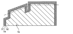
図3は、図1中のIII−III線断面図である。 3 is a cross-sectional view taken along line III-III in FIG.
図4は、本発明の一実施形態によるタコメータTが備える目盛リング1の製造工程途中品の断面図である。
FIG. 4 is a cross-sectional view of an intermediate product in the manufacturing process of the
図5は、本発明の一実施形態によるタコメータTの電気回路構成を説明する模式図である。 FIG. 5 is a schematic diagram for explaining the electric circuit configuration of the tachometer T according to the embodiment of the present invention.
コンビネーションメータ100は、当該自動車の車室内の運転席前方に運転者が視認可能に設けられ、当該自動車の作動状態に関する情報(エンジン回転速度、走行速度、エンジン冷却水温度等)およびその他の各種情報を表示している。
The
タコメータTは、当該自動車のエンジンの回転速度を表示するもので、指針8の回転角度位置により物理量の大きさを指示する、いわゆる指針計器である。
The tachometer T displays the rotational speed of the engine of the automobile, and is a so-called pointer instrument that indicates the magnitude of the physical quantity by the rotational angle position of the
タコメータTの構成について以下に説明する。 The configuration of the tachometer T will be described below.
文字盤2は、透光性材質からなる薄板、たとえば無色透明のポリカーボネート樹脂あるいはアクリル樹脂等の薄板から形成されている。文字盤2は、計器であるタコメータTの表示意匠の一部としての文字2aを備えている。
The
文字2aは、文字盤2の表面に印刷あるいはホットスタンプを施して形成されている。すなわち、文字2aの周囲部分である背景部に黒色遮光性着色層を施すとともに、文字2aを無色透明のままとする、あるいは透光性着色層を施して形成されている。本発明の一実施形態によるタコメータTでは、文字2aは透光性白色層が設けられている。このため、文字盤2背後に配置された発光ダイオード4からの光に照射されると、文字2aは黒色を背景として発光ダイオード4の発光色で発光表示される。なお、文字盤2において、後述する目盛リング1が重ねられる部分、すなわち環状部分には黒色遮光性着色層は設けられずに透明状態となっている。これにより、文字盤2背後に配置された発光ダイオード4からの光は、文字盤2の透明部分を透過して目盛リング1内に入射することができる。
The
文字盤2は、図2に示すように、その中央部に、後述するムーブメント7のシャフト7aあるいは指針8のボス部8aを挿通させるための貫通孔2bを備えている。
As shown in FIG. 2, the
装飾部材である目盛リング1は、透光性材質、たとえば無色透明のアクリル樹脂等から成型加工された基板1cにより構成されている。基板1cの前面側(視認者側、図2において左側)には、図2に示すように、大目盛1aおよび小目盛1bが突起状に形成されている。目盛リング1は、図2に示すように、文字盤2の直上に重ねて配置されている。大目盛1aは、図1に示すように、1000rpm毎に、小目盛1bは200rpm毎に、それぞれ設けられている。
The
目盛リング1の表面には、大目盛1aおよび小目盛1bの前面(視認者側の面、図2において左側の面)を除く部分に、金属被膜であるアルミ蒸着膜が形成されている。このため、目盛リング1cは、大目盛1aおよび小目盛1bの前面が透明のままであり、これらを除いた表面全域がアルミの金属調の見映えとなっている。つまり、大目盛1aおよび小目盛1bの前面が透明で、それ以外の表面は遮光性を備えている。したがって、文字盤2背後に配置された目盛リング1透過照明用の光源である発光ダイオード4からの光により目盛リング1が照射されると、大目盛1aおよび小目盛1bはアルミの金属色を背景として発光表示される。基板1cには、詳しくは、図3に示すように、基板1c側から順番に、プライマ層1d、アルミ蒸着膜1e、トップコート層1fが積層されている。
On the surface of the
プライマ層1dは、アルミ蒸着膜1eの基板1cへの食い付き性、つまり密着性を高める役割を果たしている。通常プライマはほぼ無色透明である。本発明の一実施形態によるタコメータTの目盛リング1においては、プライマに着色物質を混合して低光透過率を有するように、たとえば、光透過率を20%程度に調整したものを用いている。また、着色物質としては、たとえばカーボン粒子を用いている。
The
トップコート層1fは、無色透明または薄色着色の塗料を塗布して形成され、アルミ蒸着膜1cの表面を保護する役割を果たしている。
The
目盛リング1は、図2に示すように、文字盤2の前面側(視認者側、図2において左側)に文字盤2に重ねて配置されている。目盛リング1は、図1に示すように、後述する指針8の回動中心と同軸上に配置されている。
As shown in FIG. 2, the
目盛リング1の外周には、図1に示すように、環状部材である加飾リング3が配置されている。加飾リング3は、たとえば樹脂材料から環状に成型されている。加飾リング3は、図2に示すように、目盛リング1の保持部1hに組み合わせ、熱かしめ等で固定される。加飾リング3は、金属調等の塗装が施されており、目盛リング1の金属調外観との見映えを合わせてある。
As shown in FIG. 1, a
文字盤2の裏側(図2において右側)には、図2に示すように、目盛リング1の大目盛1aおよび小目盛1bを透過照明して発光表示するための光源である発光ダイオード4が配置されている。本発明の一実施形態によるタコメータTにおいては、発光ダイオード4は、白色発光ダイオードが用いられている。本発明の一実施形態によるタコメータTにおいては、発光ダイオード4が発する光は、目盛リング1の大目盛1aおよび小目盛1bだけではなく、文字盤2の文字2aをも透過照明してこれらを発光表示している。発光ダイオード4は、図2に示すように、文字盤2の背後に配置されたプリント基板6上に実装されている。
On the back side of the dial 2 (right side in FIG. 2), as shown in FIG. 2, a
文字盤2と発光ダイオード4と間には、図2に示すように、導光板5が配置されている。導光板5は、透光性材質、たとえば無色透明のポリカーボネート樹脂あるいはアクリル樹脂等から成型され、図1に示すように、略C字状に形成されて、文字盤2の裏面に密着して固定されている。目盛リング1は、図2に示すように、光入射部5aを備え、この光入射部5aに発光ダイオード4が発する光が入射する。導光板5は、発光ダイオード4が発する光をその内部で反射を繰り返しつつ進行させて、文字盤2に密着している面全域が均一な明るさで文字盤2を照射している。
A
文字盤2の裏側(図2において右側)には、図2に示すように、タコメータTの電気回路部を形成しているプリント基板6が配置されている。
On the back side of the dial 2 (right side in FIG. 2), as shown in FIG. 2, a printed
プリント基板6は、たとえばガラスエポキシ基板等からなり、大目盛1a、小目盛1bおよび文字2aを透過照明するための発光ダイオード4、後述する指針8を照明するための発光ダイオード9が実装されている。本発明の一実施形態によるタコメータTにおいては、発光ダイオード9は白色発光ダイオードが用いられている。プリント基板6は、タコメータTのみならず、コンビネーションメータ100全体の電気回路部を形成している。
The printed
プリント基板6には、指針8を回動させるためのムーブメント7が実装されている。ムーブメント7は、たとえば交差コイル式アクチュエータあるいはステッピングモータ等が用いられている。ムーブメント7は、外部から電圧を印加されるとトルクを発生しシャフト7aを回動させる。シャフト7aは、その先端が、図2に示すように文字盤2の表面側(図2の左側)に延出されている。シャフト7aの先端には、指針8が固定されている。
A
指針8は、透光性材料、たとえば無色透明のポリカーボネート樹脂あるいはアクリル樹脂等から形成され、図2に示すように、文字盤2の表面に沿って配置されている。指針8は、ムーブメント7が駆動されてシャフト7aが回動すると、シャフト7aと一体的に回動する。また、指針8の裏面8bには、印刷あるいはホットスタンプ等に着色(たとえば赤色)されている。指針8に入射した発光ダイオード9から発せられた光は、指針8の反射面8cで指針8の先端方向に向けて反射され、さらにこの反射光が裏面8bで運転者の視認方向に反射される。また、発光ダイオード9の発光色は白色である。これにより、指針8は、赤色で発光表示される。
The
文字盤2とプリント基板6との間には、図2に示すように、遮光筒部11aが配置されている。遮光筒部11aは略円筒状に形成されて発光ダイオード9を覆うように配置され、発光ダイオード9が発する光が指針8以外の方向に漏れることを防止している。遮光筒部11aは、後述するケーシング11と一体的に設けられている。
As shown in FIG. 2, a light
本発明の一実施形態によるタコメータTにおいては、発光ダイオード9として白色発光ダイオードを用いることにより、指針8を、指針8の裏面8bに施した着色層の色で発光表示している。したがって、裏面8bに施す着色層の色を赤色に限定する必要はなく、他の色、たとえば、橙色、緑色等に着色してもよい。一方、指針8の裏面8bに白色着色層または銀色着色層を設けるとともに、発光ダイオード9として発光色が白以外の色の発光ダイオードを用いてもよい。この場合は、指針8は、発光ダイオード9の発光色により発光表示される。
In the tachometer T according to an embodiment of the present invention, a white light emitting diode is used as the
また、指針8には、指針8の反射面8cおよびその近傍を覆う遮光キャップ10が、図2に示すように取り付けられている。遮光キャップ10は、遮光性を有する材質、たとえば黒色の樹脂材料あるいは金属等から形成され、発光ダイオード6からの光が、直接視認者の眼に入射して視認者が眩惑されることを防止している。
In addition, a
プリント基板6には、図2に示すように、発光ダイオード4、発光ダイオード5および発光ダイオード6の点灯・消灯制御およびムーブメント7の駆動制御を行うためのコントローラ15が実装されている。このコントローラ15は、たとえばマイクロコンピュータ等から構成されている。
As shown in FIG. 2, a
以上説明した、目盛リング1、文字盤2およびプリント基板6等は、ケーシング11内に収容・固定されている。ケーシング11は、たとえば樹脂材料等から形成されている。一方、文字盤2の前面側(図2において左側)には、略枠状の見返し板13が装着されている。見返し板13は、たとえば樹脂材料から形成されている。見返し板13の視認者側端部には、図2に示すように、カバー12が装着されている。カバー12は、透光性を有する樹脂あるいはガラス等の薄板から形成されている。見返し板13をおよびカバー12は、コンビネーションメータ100の見映えを整えるとともに、コンビネーションメータ100内部への埃、水分の侵入を防止している。
The
一方、ケーシング11の背後には、図2に示すように、ロアカバー14が装着されている。ロアカバー14は、たとえば樹脂材料から形成されている。
On the other hand, a
次に、本発明の一実施形態によるタコメータTの電気回路構成について、図5に基づいて説明する。 Next, an electric circuit configuration of the tachometer T according to an embodiment of the present invention will be described with reference to FIG.
図5に示すように、コントローラ15には、バッテリ17から電力が常時供給されている。また、コントローラ15は、イグニッションスイッチ16が、その作動状態(ONまたはOFF)を検出可能に接続されている。
As shown in FIG. 5, power is constantly supplied from the
コントローラ15には、図5に示すように、発光ダイオード4、発光ダイオード5およびムーブメント7が接続されている。
As shown in FIG. 5, the
コントローラ15には、図5に示すように、自動車のエンジン回転速度検出用の回転センサ18が検出信号を入力可能に接続されている。回転センサ18は、たとえば、電磁ピックアップ型が用いられており、エンジンのカムシャフト(回転速度がエンジンのクランクシャフトの回転速度の1/2)の回転数を検出可能に設置されている。
As shown in FIG. 5, a
運転者の操作によりイグニッションスイッチ16がON状態に切り替えられると、コントローラ15はそれを検知して、コンビネーションメータ100の作動を開始、すなわちタコメータTの作動を開始する。先ず、発光ダイオード4、9を点灯させる。同時に、回転センサ18からの検出信号に基づいてエンジンの回転速度を算出し、算出した走行速度を指針8が文字盤2上に指示するようにムーブメント7を駆動する。これにより、文字盤2上で、大目盛1a、小目盛1bおよび文字2aが白色で、指針8が赤色でそれぞれ発光表示されるとともに、指針8がムーブメント7により回動されてエンジンの回転速度を指示する。
When the
運転者の操作によりイグニッションスイッチ16がOFF状態に切り替えられると、コントローラ15はそれを検知して、コンビネーションメータ100の作動を停止する。すなわち、発光ダイオード4、9を消灯させる。同時に、指針8が文字盤2上において速度0r/min(revolution per minute、毎分回転数)を指示するようムーブメント7を駆動する。あるいは、ムーブメント7への通電を停止する。ムーブメント7への通電を停止した場合は、ムーブメント7のシャフト7aは、リターンスプリング(図示せず)の弾性力等により指針8が0r/minを指示する位置まで回転する。
When the
次に、本発明の一実施形態によるタコメータTの特徴である目盛リング1の製造方法について簡単に説明する。
Next, a manufacturing method of the
先ず、透光性材質、たとえば無色透明のアクリル樹脂等から成型加工により基板1cを形成する。
First, the
次に、基板1cの表面側に、図4に示すように、プライマを塗布してプライマ層1dを形成する。続いて、その上にアルミニウム蒸着処理を施してアルミ蒸着膜1eを形成する。続いて、その上にトップコートを塗布してトップコート層1fを形成する。
Next, as shown in FIG. 4, a primer is applied on the surface side of the
最後に、大目盛1aおよび小目盛1b部の先端部分、すなわち図4中の二点鎖線よりも上の部分を除去して基板1cの表面を露出させる。この結果、大目盛1aおよび小目盛1bが透明状態となる。この除去作業は、切削加工、研磨加工等により実施される。
Finally, the tip portions of the
以上により、目盛リング1が完成する。
As described above, the
次に、本発明の一実施形態によるタコメータTの特徴である目盛リング1の構成の作用効果および加飾リング3の作用効果、特に視認性におよぼす効果について説明する。
Next, the operational effects of the configuration of the
樹脂表面にアルミニウムを蒸着させてアルミ蒸着膜を形成する場合、樹脂表面にアルミが蒸着されない部分、いわゆるピンホールが発生することがある。このピンホールの大きさは大体数十ミクロンであり人の眼では見えない。 When aluminum is deposited on the resin surface to form an aluminum deposited film, a portion where aluminum is not deposited on the resin surface, so-called pinholes, may occur. The size of this pinhole is about several tens of microns and cannot be seen by human eyes.
ところで、樹脂部材の表面にアルミニウム蒸着処理を施し且つ樹脂表面の一部を透明な状態として計器の表示意匠を形成し、この表示意匠を背後の光源により透過照明する構成の車両用計器において、アルミ蒸着層にピンホールが有ると、ピンホール部分は光を透過するので、ピンホールを透過した光が視認されてしまう。すなわち、本来発光表示される表示意匠のほかにピンホール部が発光するため、車両用計器の見映えが低下する可能性がある。 By the way, in a vehicular instrument having a configuration in which an aluminum vapor deposition process is performed on the surface of a resin member and a part of the resin surface is made transparent to form a display design of the instrument, and the display design is transmitted and illuminated by a light source behind. If there is a pinhole in the vapor deposition layer, the pinhole portion transmits light, so that the light transmitted through the pinhole is visually recognized. That is, since the pinhole portion emits light in addition to the display design that is originally displayed with light emission, the appearance of the vehicle instrument may be deteriorated.
また、樹脂表面に金属被膜、たとえばアルミ蒸着層を形成する場合、樹脂表面へのアルミ蒸着層の密着力を高めるために、予め樹脂表面に液体であるプライマを塗布してプライマ層を形成している。このプライマ層は透明なため、樹脂部材背後から照射された光源からの光は、プライマ層を透過しピンホールを通過して視認者側に出射して視認される。すなわち、一般的なプライマには遮光機能、あるいは光透過制限機能はない。 In addition, when forming a metal film, for example, an aluminum vapor deposition layer on the resin surface, in order to increase the adhesion of the aluminum vapor deposition layer to the resin surface, a primer that is a liquid is applied to the resin surface in advance to form a primer layer. Yes. Since this primer layer is transparent, light from the light source irradiated from behind the resin member passes through the primer layer, passes through the pinhole, and is emitted to the viewer side to be viewed. That is, a general primer does not have a light shielding function or a light transmission limiting function.
これに対して、本発明の請求項1に記載のタコメータTにおいては、プライマ層1dとして遮光性あるいは低光透過率を有する材質を用いている。このような構成においては、目盛リング1の背後から照射された発光ダイオード4からの光は、プライマ層1dで遮断される、あるいはプライマ層1dを透過する光量が大幅に低減される。このため、ピンホールがあっても、ピンホールを通過した光はプライマ層1dで遮断あるいは減衰されて、ピンホールが発光し視認されることがない。
On the other hand, in the tachometer T according to
以上により、目盛リング1のアルミ蒸着膜にピンホールがあっても、そこから光が漏れることを阻止して良好な見映えが得られるタコメータTを提供することができる。
As described above, even if there is a pinhole in the aluminum vapor deposition film of the
なお、目盛リング1を上述した構成とすることにより、ピンホールが有ってもそこから光が漏れることを阻止することができるので、目盛リング1の製造工程における不良率、すなわちピンホールがあるために不良品となる割合を低減する、言い換えると目盛リングの歩留まりを高めることができる。
In addition, since the
ところで、目盛リング1の基板1cにプライマ層1d、アルミ蒸着膜1eおよびトップコート層1fを形成する各工程において、基板1cを治具により保持する必要がある。しかし、タコメータTの完成状態において目盛リング1の外表面となる部分、つまり運転者から見える部分は、傷等を防止するために保持することができない。そこで、予め基板1cに外周側へ突出する保持部1hを設けておき、上述の各工程では保持部1hを保持している。しかしながら、このままでは、目盛リング1外周壁面の保持部1hが視認されて、タコメータTの見映えが低下する。
By the way, in each process of forming the
そこで、目盛リング1の保持部1hに組み合わせて加飾リング3を配置すれば、上述した保持部1hを隠してタコメータTの見映えを良好なものにすることができる。
Therefore, if the
なお、以上説明した、本発明の一実施形態によるタコメータTの目盛リング1においては、基板1cに塗布されるプライマに混合する着色物質としてカーボン粒子を用いているが、カーボン粒子に限定する必要はなく、他の種類の着色物質を用いてもよい。またプライマの光透過率を20%程度に調整しているが、これに限られるものではなく必要に応じて増減してよい。
In addition, in the
また、以上説明した、本発明の一実施形態によるタコメータTの目盛リング1においては、樹脂製の基板1cに基板1c側からプライマ層1d、アルミ蒸着膜1e、トッピコート層1fを積層形成しているが、基板1cに、先ず遮光性着色層を形成し、続いてプライマ層1d、アルミ蒸着膜1e、トッピコート層1fの順に積層形成してもよい。遮光性着色層は、たとえば黒色塗装等を施して形成される。また、この場合は、プライマ層1dは、遮光性あるいは低光透過率を有する材質、あるいは無色透明のもののどちらでもよい。
Moreover, in the
また、以上説明した、本発明の一実施形態によるタコメータTでは、目盛リング1に施す金属被膜をあるアルミ蒸着膜1eとしているが、他の金属被膜であってもよい。たとえば、クロムめっき膜であってもよい。
In the tachometer T according to the embodiment of the present invention described above, the metal film applied to the
また、以上説明した、本発明の一実施形態によるタコメータTでは、大目盛1aおよび小目盛1b透過照明用の発光ダイオード4の発光色を白色としているが、白色に限る必要はなく、白以外の発光色の発光ダイオードを用いてもよい。その場合、大目盛1a、小目盛1bは、発光ダイオードの発光色で発光表示される。
Further, in the tachometer T according to the embodiment of the present invention described above, the light emission color of the
また、以上説明した、本発明の一実施形態によるタコメータTにおいては、大目盛1a、小目盛1b照明用光源として発光ダイオード4を用いているが、他の種類の光源、たとえば電球、放電等あるいはELパネル等に置き換えてもよい。
In the tachometer T according to the embodiment of the present invention described above, the
また、以上説明した実施形態はコンビネーションメータ100のタコメータTを例に説明してきたが、タコメータTに限る必要は無く、他の種類の計器、たとえば、当該自動車の走行速度を指示する速度計、燃料タンク内の残存燃料量を指示する燃料計、エンジン冷却水温度を指示する水温計等に適用してもよい。また、一つのコンビネーションメータ100内に計器を複数個備え、各計器に、以上説明した実施形態の構成による目盛リング1を備えてもよい。
In the above-described embodiment, the tachometer T of the
1 目盛リング(装飾部材)
1a 大目盛(表示意匠)
1b 小目盛(表示意匠)
1c 基板
1d プライマ層
1e アルミ蒸着膜(金属被膜)
1f トップコート層
1g 黒色塗膜(遮光性着色層)
1h 保持部
2 文字盤
2a 文字(表示意匠)
2b 貫通孔
3 加飾リング(環状部材)
4 発光ダイオード(光源)
5 導光板
6 プリント基板
7 ムーブメント
7a シャフト
8 指針
8a ボス部
8b 裏面
8c 反射面
9 発光ダイオード
10 遮光キャップ
11 ケーシング
11a 遮光筒部
12 透明カバー
13 見返し板
14 ロアカバー
15 コントローラ
16 イグニッションスイッチ
17 バッテリ
18 回転センサ
100 コンビネーションメータ
T タコメータ
1 Scale ring (decorative member)
1a Large scale (display design)
1b Small scale (display design)
1f Topcoat layer 1g Black coating (light-shielding colored layer)
2b Through
4 Light emitting diode (light source)
DESCRIPTION OF
Claims (7)
前記表示意匠を透過照明し発光表示するための光源とを備えた車両用計器であって、
前記装飾部材は、透光性材質からなり前記表示意匠が形成された基板と、該基板の前面および前記表示意匠の前面を除いた部分に前記基板側から順番に積層されたプライマ層および金属被膜から構成され、
前記プライマ層は遮光性あるいは低光透過率を有することを特徴とする車両用計器。 A decorative member having a display design of the instrument;
A vehicle instrument comprising a light source for transmitting and illuminating and displaying the display design;
The decorative member includes a substrate made of a translucent material on which the display design is formed, and a primer layer and a metal coating that are sequentially stacked from the substrate side on the front surface of the substrate and a portion other than the front surface of the display design Consisting of
The vehicle instrument according to claim 1, wherein the primer layer has a light shielding property or low light transmittance.
前記表示意匠を透過照明し発光表示するための光源とを備えた車両用計器であって、
前記装飾部材は、透光性材質からなり前記表示意匠が形成された基板と、該基板の前面および前記表示意匠の前面を除いた部分に前記基板側から順番に積層された遮光性着色層、プライマ層および金属被膜とから構成されることを特徴とする車両用計器。 A decorative member having a display design of the instrument;
A vehicle instrument comprising a light source for transmitting and illuminating and displaying the display design;
The decorative member, the light-shielding colored layer in which the display design becomes a transparent material are laminated to the substrate which is formed, in order on the front and a portion excluding the front surface of the display design of the substrate from the substrate side, A vehicular instrument comprising a primer layer and a metal coating.
Priority Applications (1)
| Application Number | Priority Date | Filing Date | Title |
|---|---|---|---|
| JP2006051179A JP4635903B2 (en) | 2006-02-27 | 2006-02-27 | Vehicle instrument |
Applications Claiming Priority (1)
| Application Number | Priority Date | Filing Date | Title |
|---|---|---|---|
| JP2006051179A JP4635903B2 (en) | 2006-02-27 | 2006-02-27 | Vehicle instrument |
Publications (2)
| Publication Number | Publication Date |
|---|---|
| JP2007232403A JP2007232403A (en) | 2007-09-13 |
| JP4635903B2 true JP4635903B2 (en) | 2011-02-23 |
Family
ID=38553143
Family Applications (1)
| Application Number | Title | Priority Date | Filing Date |
|---|---|---|---|
| JP2006051179A Expired - Fee Related JP4635903B2 (en) | 2006-02-27 | 2006-02-27 | Vehicle instrument |
Country Status (1)
| Country | Link |
|---|---|
| JP (1) | JP4635903B2 (en) |
Families Citing this family (5)
| Publication number | Priority date | Publication date | Assignee | Title |
|---|---|---|---|---|
| JP6265925B2 (en) * | 2015-01-27 | 2018-01-24 | リズム時計工業株式会社 | Assembly structure for analog watches for vehicles |
| JP5887014B1 (en) | 2015-10-19 | 2016-03-16 | 矢崎総業株式会社 | Metal-tone decorative part for vehicle display device and vehicle display device |
| JP5890576B1 (en) | 2015-10-19 | 2016-03-22 | 矢崎総業株式会社 | Metal-tone decorative part for vehicle display device and vehicle display device |
| JP5913714B1 (en) | 2015-10-19 | 2016-04-27 | 矢崎総業株式会社 | Metal-tone decorative part for vehicle display device and vehicle display device |
| JP2017144824A (en) * | 2016-02-16 | 2017-08-24 | 矢崎総業株式会社 | Decorative part for vehicle display device and vehicle display device |
Citations (5)
| Publication number | Priority date | Publication date | Assignee | Title |
|---|---|---|---|---|
| JP2001165715A (en) * | 1999-12-09 | 2001-06-22 | Yazaki Corp | Dial for instrument |
| JP2002181593A (en) * | 2000-12-15 | 2002-06-26 | Calsonic Kansei Corp | Dial structure of meter for vehicle |
| JP2005081225A (en) * | 2003-09-08 | 2005-03-31 | Calsonic Kansei Corp | Method for manufacturing plastic automobile parts having a metallic feeling |
| JP2005268688A (en) * | 2004-03-22 | 2005-09-29 | Bridgestone Corp | Light permeable electromagnetic shield material, manufacturing method of same, and display front filter having electromagnetic shield material |
| JP2006047269A (en) * | 2004-07-01 | 2006-02-16 | Denso Corp | Pointer instrument |
-
2006
- 2006-02-27 JP JP2006051179A patent/JP4635903B2/en not_active Expired - Fee Related
Patent Citations (5)
| Publication number | Priority date | Publication date | Assignee | Title |
|---|---|---|---|---|
| JP2001165715A (en) * | 1999-12-09 | 2001-06-22 | Yazaki Corp | Dial for instrument |
| JP2002181593A (en) * | 2000-12-15 | 2002-06-26 | Calsonic Kansei Corp | Dial structure of meter for vehicle |
| JP2005081225A (en) * | 2003-09-08 | 2005-03-31 | Calsonic Kansei Corp | Method for manufacturing plastic automobile parts having a metallic feeling |
| JP2005268688A (en) * | 2004-03-22 | 2005-09-29 | Bridgestone Corp | Light permeable electromagnetic shield material, manufacturing method of same, and display front filter having electromagnetic shield material |
| JP2006047269A (en) * | 2004-07-01 | 2006-02-16 | Denso Corp | Pointer instrument |
Also Published As
| Publication number | Publication date |
|---|---|
| JP2007232403A (en) | 2007-09-13 |
Similar Documents
| Publication | Publication Date | Title |
|---|---|---|
| WO2016021102A1 (en) | Vehicle display device | |
| JP5256603B2 (en) | Indicator dial | |
| JP5182216B2 (en) | Vehicle display device | |
| JP4635903B2 (en) | Vehicle instrument | |
| JP2006003341A (en) | Display | |
| JP4437550B2 (en) | Vehicle indicator instrument | |
| JP4665804B2 (en) | Vehicle instrument | |
| KR100660673B1 (en) | Combination meter for cars | |
| JP4403978B2 (en) | Display board | |
| JP6256248B2 (en) | Vehicle display device | |
| JP2007309837A (en) | Display | |
| JP2009139146A (en) | Pointer meter | |
| JP2007085858A (en) | Pointer instrument for vehicle | |
| JP4858228B2 (en) | Pointer instrument | |
| JP3812540B2 (en) | Vehicle instrument | |
| JP2007101358A (en) | Measuring instrument for vehicle | |
| JP4075843B2 (en) | Vehicle indicator instrument | |
| JP2007121038A (en) | Dial for instrument | |
| JP4655900B2 (en) | Vehicle instrument | |
| JP5018350B2 (en) | Vehicle instrument | |
| JP4259480B2 (en) | Vehicle instrument | |
| JP2007304066A (en) | Pointer instrument for vehicle | |
| JP4175321B2 (en) | Pointer instrument | |
| JP2005309157A (en) | Display device | |
| JP2005345287A (en) | Pointer meter |
Legal Events
| Date | Code | Title | Description |
|---|---|---|---|
| A621 | Written request for application examination |
Free format text: JAPANESE INTERMEDIATE CODE: A621 Effective date: 20080317 |
|
| A977 | Report on retrieval |
Free format text: JAPANESE INTERMEDIATE CODE: A971007 Effective date: 20100114 |
|
| A131 | Notification of reasons for refusal |
Free format text: JAPANESE INTERMEDIATE CODE: A131 Effective date: 20100316 |
|
| A521 | Written amendment |
Free format text: JAPANESE INTERMEDIATE CODE: A523 Effective date: 20100416 |
|
| TRDD | Decision of grant or rejection written | ||
| A01 | Written decision to grant a patent or to grant a registration (utility model) |
Free format text: JAPANESE INTERMEDIATE CODE: A01 Effective date: 20101026 |
|
| A01 | Written decision to grant a patent or to grant a registration (utility model) |
Free format text: JAPANESE INTERMEDIATE CODE: A01 |
|
| A61 | First payment of annual fees (during grant procedure) |
Free format text: JAPANESE INTERMEDIATE CODE: A61 Effective date: 20101108 |
|
| FPAY | Renewal fee payment (event date is renewal date of database) |
Free format text: PAYMENT UNTIL: 20131203 Year of fee payment: 3 |
|
| R151 | Written notification of patent or utility model registration |
Ref document number: 4635903 Country of ref document: JP Free format text: JAPANESE INTERMEDIATE CODE: R151 |
|
| FPAY | Renewal fee payment (event date is renewal date of database) |
Free format text: PAYMENT UNTIL: 20131203 Year of fee payment: 3 |
|
| R250 | Receipt of annual fees |
Free format text: JAPANESE INTERMEDIATE CODE: R250 |
|
| R250 | Receipt of annual fees |
Free format text: JAPANESE INTERMEDIATE CODE: R250 |
|
| R250 | Receipt of annual fees |
Free format text: JAPANESE INTERMEDIATE CODE: R250 |
|
| R250 | Receipt of annual fees |
Free format text: JAPANESE INTERMEDIATE CODE: R250 |
|
| R250 | Receipt of annual fees |
Free format text: JAPANESE INTERMEDIATE CODE: R250 |
|
| R250 | Receipt of annual fees |
Free format text: JAPANESE INTERMEDIATE CODE: R250 |
|
| LAPS | Cancellation because of no payment of annual fees |