JP4626413B2 - Composite magnetic material, coil antenna structure, and portable communication terminal - Google Patents
Composite magnetic material, coil antenna structure, and portable communication terminal Download PDFInfo
- Publication number
- JP4626413B2 JP4626413B2 JP2005174047A JP2005174047A JP4626413B2 JP 4626413 B2 JP4626413 B2 JP 4626413B2 JP 2005174047 A JP2005174047 A JP 2005174047A JP 2005174047 A JP2005174047 A JP 2005174047A JP 4626413 B2 JP4626413 B2 JP 4626413B2
- Authority
- JP
- Japan
- Prior art keywords
- magnetic
- magnetic material
- main surface
- coil antenna
- powder
- Prior art date
- Legal status (The legal status is an assumption and is not a legal conclusion. Google has not performed a legal analysis and makes no representation as to the accuracy of the status listed.)
- Expired - Fee Related
Links
Images


Landscapes
- Soft Magnetic Materials (AREA)
- Support Of Aerials (AREA)
Description
この発明は、主としてRFIDシステムの使用周波数において利用される複合磁性体材料、ならびにそれを用いて構成されるコイルアンテナ構造および携帯型通信端末に関する。 The present invention relates to a composite magnetic material used mainly at a use frequency of an RFID system, and a coil antenna structure and a portable communication terminal configured using the same.
近年、鉄道の自動改札機、建物の入退出におけるセキュリティシステム、または電子マネーシステムの分野では、非接触式のICカードやICタグなどを用いた、いわゆるRFID(Radio Frequency IDentification:非接触データ識別技術、電波方式認識)システムの導入が進められている。 Recently, railway automatic ticket gate, the security system in the entry and exit of the building or in the field of electronic money system, was used an IC card or an IC tag of the non-contact type, so-called RFID (R adio F requency ID entification : contactless Data identification technology and radio wave system recognition) systems are being introduced.
このRFIDシステムは、データの送受信および記憶を行なうICチップが内蔵されている非接触式ICカードと、この非接触式ICカードに対してデータの書き込みや読み出しを行なうリーダライタとから構成されており、電磁誘導の原理に基づいて、リーダライタ側のアンテナから電磁波が放射されると、放射された電磁波が誘導結合によって非接触式ICカード側のアンテナと磁気的に結合し、非接触でデータの送受信に必要な電力が供給されることにより、非接触式ICカードとリーダライタとの間の通信が行なわれる。 This RFID system is composed of a non-contact IC card having an IC chip for transmitting / receiving and storing data, and a reader / writer for writing / reading data to / from the non-contact IC card. Based on the principle of electromagnetic induction, when electromagnetic waves are radiated from an antenna on the reader / writer side, the radiated electromagnetic waves are magnetically coupled to the antenna on the non-contact type IC card side by inductive coupling, and data is transmitted without contact. Communication between the non-contact IC card and the reader / writer is performed by supplying power necessary for transmission and reception.
ところで近年、上述したRFIDシステムにおける非接触式ICカードの代わりに、ICチップを携帯型通信端末に内蔵し、リーダライタと誘導結合する技術が実用化されつつある。このような携帯型通信端末では、回路基板にパターン型コイルアンテナを携帯型通信端末の筐体のいずれか一方の面(表面付近)に設けることになるが、携帯型通信端末の内部にはアース電極を含む回路基板やバッテリーケース等の導電体があり、アンテナに磁束が通りにくい状態になっているため、通信距離が短いという問題がある。 By the way, in recent years, a technique of incorporating an IC chip in a portable communication terminal and inductively coupling with a reader / writer instead of the contactless IC card in the RFID system described above has been put into practical use. In such a portable communication terminal, a pattern type coil antenna is provided on a circuit board on one side (near the surface) of the casing of the portable communication terminal. There are conductors such as a circuit board and a battery case including electrodes, and it is difficult for magnetic flux to pass through the antenna. Therefore, there is a problem that a communication distance is short.
そこで特許文献1には、効率的にアンテナに磁束を通すため、金属材からなる対象物の被着面とアンテナとの間に介在するように配置された磁性体部材(高透磁率材料シート)を設け、外部から与えられる電磁波を磁性体部材内に通して対象物の被着面に漏らさないようにすることにより、効率良くアンテナコイル内を通過させることができる情報記憶装置の構成が開示されており、磁性体部材としてセンダスト合金(Fe−Al−Si系合金)を用いることが記載されている。
Therefore, in
一方特許文献2には、通信可能な範囲を拡大するための別の技術として、リーダライタ側のコイルアンテナのICカードと対向する主面とは反対側の主面に対向して磁気特性と形状が必要に応じて設定された磁性体部材を配置し、その磁性体部材内にコイルアンテナからの磁束を通す技術について開示されており、その磁性体部材としてアモルファス合金、Co−Cr系合金、Fe−Al系合金、センダスト合金、Fe−Ni合金、Fe−Co−Ni合金をゴム系のバインダ中に分散させた複合磁性体材料や、それらをメッキ法やスパッタ法により形成した薄膜材料、またはそれらをプレス焼結したバルク薄板を用いることが記載されている。
ここで、特許文献1に開示されている情報記憶装置は、対象物の被着面に貼り付ける構造であるので、これを携帯型通信端末に適用する場合には、例えばバッテリーケースに貼り付けることにより携帯型通信端末に組み込むことができる。
Here, since the information storage device disclosed in
ところが上記の構造では、筐体の一方面側からの磁束に対しては有効であるが、その反対の他方面からの磁束に対しては効果を奏しないため、携帯型通信端末の表裏を逆にしてリーダライタにかざすと通信ができなくなるという問題がある。 However, the above structure is effective for the magnetic flux from one side of the casing, but has no effect on the magnetic flux from the other side of the casing. However, there is a problem that communication cannot be performed if it is held over a reader / writer.
携帯型通信端末の表裏どちら側からでもリーダライタとの通信を行なうためには、例えば携帯型通信端末内部に配置されているアース電極を含む回路基板やバッテリーケース等の導電体を迂回するように磁性体部材を配置して、その磁性体部材を経路として表裏両面から電磁波を送受信できるようにすれば良いが、それに用いる磁性体材料としては、自由に形状加工でき、かつ形状加工後には形状固定できる、樹脂中に磁性体粉末を分散させた複合磁性体材料で、導電体に流れる電流が磁界結合して渦電流を発生しない、すなわちジュール熱による発熱等の損失のない、抵抗率が高いものが必要になる。 In order to communicate with the reader / writer from either the front or back side of the portable communication terminal, for example, a conductor such as a circuit board or a battery case including a ground electrode arranged inside the portable communication terminal is bypassed. It is only necessary to place a magnetic member so that electromagnetic waves can be transmitted and received from both the front and back surfaces using the magnetic member as a path. However, the magnetic material used for the magnetic member can be freely shaped and fixed after shaping. A composite magnetic material in which magnetic powder is dispersed in a resin that does not generate eddy current due to magnetic coupling of the current flowing through the conductor, that is, has no loss such as heat generation due to Joule heat, and has a high resistivity Is required.
しかしながら、特許文献2に開示されている複合磁性体材料は、高い比透磁率μ´を得ることを主眼としているため、複合磁性体材料中の磁性体粉末として抵抗率の低い金属材料を用いており、RFIDシステムの使用周波数において必要な磁気特性と、高い抵抗率とを両立できていない。
However, since the composite magnetic material disclosed in
そこで、この発明の目的は、上述したような問題を解決し得る、すなわち非接触型の情報担体用リーダ及び前記リーダを接続する携帯型通信端末のコイルアンテナ構造の磁性体部材であり、一方面側から他方面側への磁束の経路として用いるための、RFIDシステムの使用周波数(例えば13.56MHz)における比透磁率が高く、抵抗率が高く、自由に形状加工でき、かつ形状加工後には形状固定できる、複合磁性体材料を提供しようとすることである。 Accordingly, an object of the present invention is a magnetic member having a coil antenna structure for a non-contact type information carrier reader and a portable communication terminal to which the reader is connected, which can solve the above-described problems. High relative permeability at high frequency (for example, 13.56 MHz) of the RFID system for use as a magnetic flux path from one side to the other side, high resistivity, free shape processing, and shape after shape processing It is to provide a composite magnetic material that can be fixed.
上述した技術的課題を解決するため、この発明の複合磁性体材料は、磁性体粉末と樹脂とを含む複合磁性体材料であって、前記磁性体粉末が、組成式:xNiO−yMeO−zZnO−(1−x−y−z)Fe2O3(ただしMeはCu、MgおよびCoのうちの少なくとも1種であり、x、yおよびzはモル比)で表わされる組成を有し、前記組成式におけるx、yおよびzが、0.47≦x+y≦0.50(ただし、x>0)、0.10≦z≦0.35の範囲内にある主成分100重量部に対して、Mn化合物である副成分を、MnOに換算して0.05〜0.77重量部含有するスピネルフェライトであり、前記磁性体粉末の含有量が、35〜80体積%であることを特徴としている。 In order to solve the technical problem described above, the composite magnetic material of the present invention is a composite magnetic material containing a magnetic powder and a resin, and the magnetic powder has a composition formula: xNiO-yMeO-zZnO-. (1-xyz) Fe 2 O 3 (wherein Me is at least one of Cu, Mg and Co, and x, y and z are molar ratios), and the composition X, y and z in the formula are 0.47 ≦ x + y ≦ 0.50 (where x> 0) and 100 parts by weight of the main component within the range of 0.10 ≦ z ≦ 0.35, Mn Spinel ferrite containing 0.05 to 0.77 parts by weight of a subcomponent which is a compound in terms of MnO, and the content of the magnetic substance powder is 35 to 80% by volume.
また、前記磁性体粉末中のMn化合物である副成分は、MnOに換算して0.07〜0.58重量部であることが好ましい。 Moreover, it is preferable that the subcomponent which is a Mn compound in the said magnetic body powder is 0.07-0.58 weight part converted into MnO.
そして、この発明のコイルアンテナ構造は、第1主面およびそれに対向する第2主面を有する板状の筐体を備え、該筐体内に当該筐体の少なくとも厚み方向に延びて第1主面側から第2主面側への磁路となる第1の磁性体部材と、前記筐体の第1主面側に設けられ前記第1の磁性体部材に磁気的に接続された第2の磁性体部材と、前記筐体の第2主面側に設けられ前記第1の磁性体部材に磁気的に接続された第3の磁性体部材と、前記第1の磁性体部材を取り巻くコイル部材とを備えたコイルアンテナ構造であって、少なくとも前記第1の磁性体部材が上述したこの発明に係る複合磁性体材料からなることを特徴としている。 The coil antenna structure of the present invention includes a plate-shaped housing having a first main surface and a second main surface facing the first main surface, and extends in the thickness direction of the housing at least in the housing. A first magnetic member serving as a magnetic path from the side to the second main surface side, and a second magnetic member provided on the first main surface side of the housing and magnetically connected to the first magnetic member A magnetic member, a third magnetic member provided on the second main surface side of the housing and magnetically connected to the first magnetic member, and a coil member surrounding the first magnetic member And at least the first magnetic member is made of the composite magnetic material according to the present invention described above.
また、この発明のコイルアンテナ構造は、前記第1の磁性体部材が、電源用コネクタのレセプタクルにおけるハウジング部材と共用されていてもよい。 In the coil antenna structure of the present invention, the first magnetic member may be shared with the housing member in the receptacle of the power connector.
そして、この発明の携帯型通信端末は、上述したこの発明に係るコイルアンテナ構造を備えることを特徴としている。 And the portable communication terminal of this invention is provided with the coil antenna structure which concerns on this invention mentioned above.
この発明の複合磁性体材料は、磁性体粉末と樹脂とを含む複合磁性体材料であって、前記磁性体粉末が、組成式:xNiO−yMeO−zZnO−(1−x−y−z)Fe2O3(ただしMeはCu、MgおよびCoのうちの少なくとも1種であり、x、yおよびzはモル比)で表わされる組成を有し、前記組成式におけるx、yおよびzが、0.47≦x+y≦0.50(ただし、x>0)、0.10≦z≦0.35の範囲内にある主成分100重量部に対して、Mn化合物である副成分を、MnOに換算して0.05〜0.77重量部含有するスピネルフェライトであり、前記磁性体粉末の含有量が、35〜80体積%となるようにしているので、RFIDシステムの使用周波数(例えば13.56MHz)における比透磁率が高く、自由に形状加工でき、かつ形状加工後には形状固定できる。そのため、非接触型の情報担体用リーダ及び前記リーダを接続する携帯型通信端末のコイルアンテナ構造の磁性体部材であり、一方面側から他方面側への磁束の経路として用いることができる。 The composite magnetic material of the present invention is a composite magnetic material containing a magnetic powder and a resin, and the magnetic powder has a composition formula: xNiO-yMeO-zZnO- (1-xyz) Fe. 2 O 3 (wherein Me is at least one of Cu, Mg, and Co, and x, y, and z are molar ratios), and x, y, and z in the composition formula are 0 .47 ≦ x + y ≦ 0.50 (where x> 0) and 100 parts by weight of the main component in the range of 0.10 ≦ z ≦ 0.35, the subcomponent that is a Mn compound is converted to MnO Since the spinel ferrite contains 0.05 to 0.77 parts by weight and the content of the magnetic substance powder is 35 to 80% by volume, the operating frequency of the RFID system (for example, 13.56 MHz) ) Has a high relative permeability and It can shaping in, and after shaping can form-locking. Therefore, it is a non-contact type information carrier reader and a magnetic member of a coil antenna structure of a portable communication terminal to which the reader is connected, and can be used as a magnetic flux path from one side to the other side.
さらにこの発明の複合磁性体材料は抵抗率が十分高いため、アンテナの受信感度を上げることができ、また抵抗率が十分高ければ渦電流の発生が抑えられ、それによる損失が少ないことから、外部からの電圧が印加される携帯型通信端末のレセクタプル(嵌脱可能なプラグとともに外部電源と接続するための電源用コネクタを構成する部品)におけるハウジング部材(プラグを嵌合する筐体)をアンテナとして共用することができる。またレセプタクルと共用した場合には、バッテリーケースによる電磁波の遮蔽の影響が少ない領域をアンテナとして有効利用できるため、リーダライタとの誘導結合に対する指向性の更なる改善と、充電時の損失や電流漏洩を発生させることなく携帯型情報端末の小型化を進めることができる。 Furthermore, since the composite magnetic material of the present invention has a sufficiently high resistivity, the reception sensitivity of the antenna can be increased, and if the resistivity is sufficiently high, the generation of eddy currents can be suppressed and the loss caused thereby can be reduced. A housing member (a casing in which a plug is fitted) in a re-sector pull (a component constituting a power connector for connecting to an external power source together with a detachable plug) of a portable communication terminal to which a voltage from the antenna is applied is used as an antenna Can be shared. In addition, when used in common with a receptacle, an area that is less affected by electromagnetic interference from the battery case can be used effectively as an antenna, further improving directivity for inductive coupling with the reader / writer, and loss and current leakage during charging. Miniaturization of the portable information terminal can be promoted without generating any.
この顕著な電磁気特性の改善効果は、Mn化合物である副成分を、MnOに換算して0.05〜0.77重量部含有させることと、主成分を表す組成式のz、すなわちZnOの含有比率を所定の範囲に調製したことの相乗効果によるものであり、特にZnOの含有比率を所定の範囲に調製したことだけでは得られない抵抗率の向上が、Mn化合物の添加によってもたらされていると考えられる。 This remarkable improvement effect of electromagnetic characteristics is that the subcomponent which is a Mn compound is contained in an amount of 0.05 to 0.77 parts by weight in terms of MnO, and z in the composition formula representing the main component, that is, the inclusion of ZnO. This is due to a synergistic effect of adjusting the ratio within a predetermined range, and in particular, an increase in resistivity that cannot be obtained only by adjusting the content ratio of ZnO within a predetermined range is brought about by the addition of the Mn compound. It is thought that there is.
特に、Mn化合物である副成分を、MnOに換算して0.07〜0.58重量部含有させた場合、その効果は顕著なものがあり好ましい。 In particular, when the subcomponent which is a Mn compound is contained in an amount of 0.07 to 0.58 parts by weight in terms of MnO, the effect is remarkable and preferable.
この発明の複合磁性体材料は、上記のような優れた電磁気特性を有し、また形状加工の自由度が高いため、携帯型通信端末として例えば携帯電話機等に適用することで、小型化、高機能化を進めることができる。 Since the composite magnetic material of the present invention has excellent electromagnetic characteristics as described above and has a high degree of freedom in shape processing, it can be reduced in size and height when applied to, for example, a mobile phone as a portable communication terminal. Functionalization can be promoted.
まず、この発明の複合磁性体材料が適用されるコイルアンテナ、および携帯型通信端末の一例である携帯電話機について説明する。 First, a coil antenna to which the composite magnetic material of the present invention is applied and a mobile phone as an example of a portable communication terminal will be described.
図1は、この発明の複合磁性体材料を用いて構成されるコイルアンテナの基本的構造を図解的に示す断面図である。 FIG. 1 is a cross-sectional view schematically showing the basic structure of a coil antenna constructed using the composite magnetic material of the present invention.
コイルアンテナ1は、例えばアース電極を含む回路基板やバッテリーケース等、所定の厚みと面方向の広がりを持つ導電体2の端部と第1主面(図中上側)および第2主面(図中下側)の一部を覆うように配設されている。すなわち、このコイルアンテナ1は導電体2の端部に導電体2の厚み方向に延びる第1の磁性体部材を備え、この第1の磁性体部材に対し、導電体2の第1主面側に第2の磁性体部材が磁気的に接続されており、さらに導電体2の第2主面側に第3の磁性体部材が磁気的に接続されている。また、第1の磁性体部材には、それを取り巻くように導体を巻回したコイル部材4(ピックアップコイル)を設けている。ここで図1は、コイルアンテナ1の第1〜3の磁性体部材が一体成形された例を示しており、この一体成形された磁性体部材3が、この発明の複合磁性体材料により構成されている。第1〜3の磁性体部材は磁気的に接続されていればよく、それぞれを独立して成形し、後で接合しても差し支えない。
The
図中Hで示すように、磁界が上方に向けて印加されているとき、磁束は導電体2の第2主面側の磁性体部材に入射し、第2主面側の磁性体部材→端部の磁性体部材→第1主面側の磁性体部材という経路を辿って上方へ抜ける。
As indicated by H in the figure, when the magnetic field is applied upward, the magnetic flux enters the magnetic member on the second main surface side of the
このようにコイル部材4が巻回され、また導電体2を迂回するように断面がコの字型に配設された磁性体部材3を用いることにより、両主面からの磁束が磁性体部材3を経路としてコイル部4が巻回された部分に収束されるので、磁束Hが変調されているとき、それを信号または電力としてコイル部材4から取り出すことができる。
By using the
このような構造のコイルアンテナであれば、第2の磁性体部材側または第3の磁性体部材側のどちらの面であっても、導電体2の厚み方向に電界が向く領域にかざす、または置くだけで外部に設置されているリーダライタ等の回路と誘導結合させることができ、コイル部材4に接続された回路の動作による出力信号やリーダライタ側からの入力信号を確実に送受信することができる。
In the case of the coil antenna having such a structure, the surface is held over the region where the electric field is directed in the thickness direction of the
また前述のように、携帯型通信端末のレセクタプルにおけるハウジング部材をアンテナとして共用した場合には、バッテリーケースによる電磁波の遮蔽の影響が少ない領域をアンテナとして有効利用できるため、リーダライタとの誘導結合に対する指向性の更なる改善と、充電時の損失や電流漏洩を発生させることなく携帯型情報端末の小型化を進めることができる。 In addition, as described above, when the housing member in the re-sector pull of the portable communication terminal is shared as an antenna, an area that is less affected by the shielding of electromagnetic waves by the battery case can be effectively used as an antenna. Further improvement of directivity and downsizing of the portable information terminal can be promoted without causing loss or current leakage during charging.
図2は図1のような構造を持つコイルアンテナを実装した携帯電話機の基本的構造を図解的に示す断面図である。 FIG. 2 is a cross-sectional view schematically showing the basic structure of a mobile phone on which a coil antenna having the structure shown in FIG. 1 is mounted.
図2を参照して、携帯電話機10の筐体5は全体に板状を成していて、筐体5の内部には電子回路を構成する基板6が配設されている。筐体5の端部には、コイルアンテナ1が内部に配設されており、コイルアンテナ1の磁性体部材3は、基板6を迂回して、基板6の端部と第1主面(図中上側)および第2主面(図中下側)の一部を覆うように配設されている。コイル部材4にはデータの送受信および記憶を行なうICチップ(図示しない)が接続されている。また筐体5のコイルアンテナ1を配設した端部とは反対側の端部には、携帯電話機としてのアンテナ7が設けられている。
Referring to FIG. 2, the
このようにしてコイル部材4が巻回された磁性体部材3をコの字型に構成して筐体内に配置することにより、磁性体部分3で収束した磁束による誘導結合で、ICチップに電力供給および信号の送受信ができる。そのため、携帯電話機の表裏に関係なくリーダライタ(図示しない)との相互通信が可能となる。
In this way, the
次に、図1に示したコイルアンテナ1に備えられる磁性体部材3のように、RFIDシステムの使用周波数(例えば13.56MHz)における電気的特性に優れ、また携帯型通信端末の小型化に対して有利に用いられる、この発明の複合磁性体材料について説明する。
Next, like the
この発明の複合磁性体材料は、磁性体粉末と樹脂とを含むものであって、前記磁性体粉末が、組成式:xNiO−yMeO−zZnO−(1−x−y−z)Fe2O3(ただしMeはCu、MgおよびCoのうちの少なくとも1種であり、x、yおよびzはモル比)で表わされる組成を有し、前記組成式におけるx、yおよびzが、0.47≦x+y≦0.50(ただし、x>0)、0.10≦z≦0.35の範囲内にある主成分100重量部に対して、Mn化合物である副成分を、MnOに換算して0.05〜0.77重量部含有するスピネルフェライトであり、前記磁性体粉末の含有量が、35〜80体積%となるようにしている。 Composite magnetic material of this invention is one comprising a magnetic powder and a resin, the magnetic substance powder, the composition formula: xNiO-yMeO-zZnO- (1 -x-y-z) Fe 2 O 3 (Where Me is at least one of Cu, Mg and Co, and x, y and z are molar ratios), and x, y and z in the composition formula are 0.47 ≦ x + y ≦ 0.50 (where x> 0) and 100 parts by weight of the main component in the range of 0.10 ≦ z ≦ 0.35, the subcomponent as a Mn compound is converted to MnO and 0. 0.05 to 0.77 parts by weight of spinel ferrite, and the content of the magnetic powder is set to 35 to 80% by volume.
また、この発明の複合磁性体材料は、前記磁性体粉末中のMn化合物である副成分が、MnOに換算して0.07〜0.58重量部であることが好ましい。 In the composite magnetic material of the present invention, the subcomponent which is a Mn compound in the magnetic powder is preferably 0.07 to 0.58 parts by weight in terms of MnO.
この発明において、上述のような特定的な組成を選んだ根拠となる実施例について、以下に説明する。 In the present invention, examples that serve as the basis for selecting a specific composition as described above will be described below.
この発明の複合磁性体材料は、所定の体積比率のスピネルフェライトである磁性体粉末および樹脂から構成されている。まずスピネルフェライトである磁性体粉末の出発原料として、高純度の酸化ニッケル(NiO)、酸化銅(CuO)、酸化マグネシウム(MgO)、酸化コバルト(Co2O3)、酸化亜鉛(ZnO)、酸化鉄(Fe2O3)、および酸化マンガン(MnO2)の各粉末を準備した。 The composite magnetic material of the present invention is composed of a magnetic powder and a resin that are spinel ferrite having a predetermined volume ratio. First, as a starting material for magnetic powder that is spinel ferrite, high-purity nickel oxide (NiO), copper oxide (CuO), magnesium oxide (MgO), cobalt oxide (Co 2 O 3 ), zinc oxide (ZnO), oxidation Each powder of iron (Fe 2 O 3 ) and manganese oxide (MnO 2 ) was prepared.
次に、表1に示すx、y、z、およびMe元素種にそれぞれ選ばれた、組成式:xNiO−yMeO−zZnO−(1−x−y−z)Fe2O3(ただしMeはCu、MgおよびCoのうちの少なくとも1種であり、x、yおよびzはモル比)で表される主成分100重量部に対し、Mn化合物である副成分を、MnOに換算して表1に示す重量部含有した磁性体粉末が得られるように、前記の各出発原料粉末を調合した。 Next, selected x shown in Table 1, y, z, and Me elemental species respectively, formula: xNiO-yMeO-zZnO- (1 -x-y-z) Fe 2 O 3 ( where Me is Cu , Mg, and Co, and x, y, and z are molar ratios), and 100 parts by weight of the main component is expressed in Table 1. Each of the above starting raw material powders was prepared so as to obtain a magnetic powder containing the indicated parts by weight.
次に、この調合粉末に純水を加え、5mmφのPSZまたはスチールボールをメディアとしたボールミルを用いて24時間湿式混合し、均一に分散させた後、脱水および乾燥処理を施して調整粉末を得た。 Next, pure water is added to this blended powder, wet mixed for 24 hours using a ball mill using 5 mmφ PSZ or steel balls as a medium, dispersed uniformly, and then subjected to dehydration and drying to obtain adjusted powder. It was.
次に、この調整粉末を、大気中にて950℃の温度で2時間仮焼し、得られた仮焼粉末を乾式粉砕機で5時間解砕することにより、所定の組成の磁性体粉末を得た。得られた磁性体粉末を光回折式の粒度分布計で測定したところ、平均粒径は4.3μmであり、またBET法による比表面積は1.5m2/gであった。さらに得られた磁性体粉末について、CuKα線を用いたX線回折を行ない、その回折ピーク位置をフィッティング解析したところ、スピネル構造のフェライト単相となっていることが確認された。 Next, this adjusted powder is calcined in the atmosphere at a temperature of 950 ° C. for 2 hours, and the obtained calcined powder is pulverized for 5 hours by a dry pulverizer to obtain a magnetic powder having a predetermined composition. Obtained. When the obtained magnetic powder was measured with a light diffraction particle size distribution analyzer, the average particle size was 4.3 μm, and the specific surface area by the BET method was 1.5 m 2 / g. Further, the obtained magnetic powder was subjected to X-ray diffraction using CuKα rays, and the diffraction peak position was subjected to fitting analysis. As a result, it was confirmed that the magnetic powder had a single phase of spinel ferrite.
次に、得られた磁性体粉末の粉体真密度をピクノメータ法により測定し、磁性体粉末とゲル浸透クロマトグラフィーで測定した重量平均分子量6000のポリプロピレン樹脂とが、体積比で磁性体粉末:ポリプロピレン樹脂=35:65となるように調合した。 Next, the true powder density of the obtained magnetic powder is measured by a pycnometer method, and the magnetic powder and the polypropylene resin having a weight average molecular weight of 6000 measured by gel permeation chromatography are magnetic powder: polypropylene. The resin was blended to be 35:65.
次に、上記の調合粉末を処理温度180℃の熱ロールで1時間処理して混合し、混合後の粉末を温度180℃、圧力150MPaで直径10mm、厚さ10mmの円筒状にプレス成形し、スピネルフェライトである磁性体粉末および樹脂から構成される複合磁性体材料を得た。 Next, the above prepared powder is processed and mixed with a heat roll at a processing temperature of 180 ° C. for 1 hour, and the mixed powder is press-molded into a cylindrical shape having a diameter of 10 mm and a thickness of 10 mm at a temperature of 180 ° C. and a pressure of 150 MPa, A composite magnetic material composed of a magnetic powder that is spinel ferrite and a resin was obtained.
このようにして得られた各組成の複合磁性体材料の上下面に、Ag粉末を導電性材料として含む導電性樹脂を用いて電極を形成することにより、電磁気特性測定用試料とした。 Electromagnetic property measurement samples were obtained by forming electrodes on the upper and lower surfaces of the composite magnetic material of each composition thus obtained using a conductive resin containing Ag powder as a conductive material.
上記の電磁気特性測定用試料について、測定周波数10MHzでの比透磁率μ´と、印加電圧100Vでの抵抗率ρをそれぞれ室温で測定した。各試料組成に対応した比透磁率μ´および抵抗率ρの測定結果を表1に示す。 With respect to the sample for measuring electromagnetic characteristics, the relative permeability μ ′ at a measurement frequency of 10 MHz and the resistivity ρ at an applied voltage of 100 V were measured at room temperature. Table 1 shows the measurement results of relative permeability μ ′ and resistivity ρ corresponding to each sample composition.
また、上記の電磁気特性測定用試料について、比透磁率μ´の周波数特性を室温で測定した。その測定結果を図3に示す。 Further, the frequency characteristic of the relative magnetic permeability μ ′ of the above sample for measuring electromagnetic characteristics was measured at room temperature. The measurement results are shown in FIG.
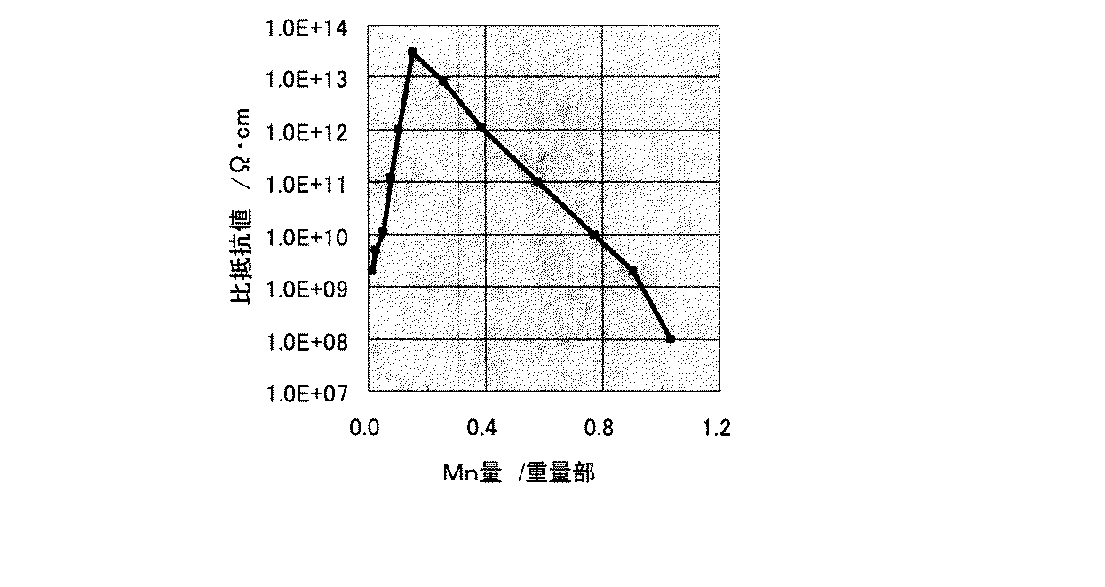
また、組成式:0.20NiO−0.20CoO−0.10ZnO−0.50Fe2O3で表される主成分100重量部に対し、Mn化合物である副成分を、MnOに換算して0.02〜1.4重量部の範囲内にある種々の量を含有した磁性体粉末と、重量平均分子量6000のポリプロピレン樹脂とから構成される複合磁性体材料を、上記と同様の方法、同様の体積比で作製し、電極を形成した後、印加電圧100Vでの抵抗率ρをそれぞれ室温で測定した。各試料組成に対応した抵抗率ρの測定結果を図4に示す。
Further, the composition formula: to 100 parts by weight of the main component represented by 0.20NiO-0.20CoO-0.10ZnO-0.50Fe 2
さらに、組成式:0.47NiO−0.10ZnO−0.43Fe2O3で表される主成分100重量部に対し、Mn化合物である副成分を、MnOに換算して0.2重量部の範囲内にある種々の量を含有した磁性体粉末(表1の試料2と同じ組成)と、重量平均分子量6000のポリプロピレン樹脂とから構成される複合磁性体材料を、上記と同様の方法で体積比を変えて作製し、電極を形成した後、測定周波数10MHzでの比透磁率μ´と、印加電圧100Vでの抵抗率ρをそれぞれ室温で測定した。各試料組成に対応した比透磁率μ´および抵抗率ρの測定結果を表2に示す。
Furthermore, with respect to 100 parts by weight of the main component represented by the composition formula: 0.47NiO-0.10ZnO-0.43Fe 2 O 3 , the subcomponent as the Mn compound is converted to 0.2 parts by weight in terms of MnO. A composite magnetic material composed of a magnetic powder containing various amounts within the range (same composition as
なお、表1および2において、試料番号に*を付したものは、この発明の範囲外の試料である。 In Tables 1 and 2, the sample number with * is a sample outside the scope of the present invention.
まず、表1に示すように、この発明の範囲内にある試料2、3、および6〜8に係る複合磁性体材料では、比透磁率μ´が8以上と実用上十分高く、また抵抗率ρが1.0×10¹⁰Ω・cm以上と高い、優れた電磁気特性が得られている。
First, as shown in Table 1, in the composite magnetic materials according to
また、図3に示すように、この発明の範囲内にある試料2、3、および6〜8に係る複合磁性体材料では、RFIDシステムの使用周波数である13.56MHzまで比透磁率μ´の落ち込みのない、優れた高周波特性が得られている。
Further, as shown in FIG. 3, in the composite magnetic material according to
また、図4に示すように、この発明の範囲内である、Mn化合物である副成分を、MnOに換算して0.05〜0.77重量部含有する複合磁性体材料では、抵抗率ρが1.0×10¹⁰Ω・cm以上と高い、優れた絶縁特性が得られている。 Further, as shown in FIG. 4, in the composite magnetic material containing 0.05 to 0.77 parts by weight in terms of MnO, the subcomponent that is a Mn compound within the scope of the present invention is used for resistivity ρ. Has an insulating property as high as 1.0 × 10 10 Ω · cm or more.
この発明の複合磁性体材料は上記のように優れた絶縁特性を有し、渦電流の発生およびそれによる損失が少ないことから、携帯型通信端末のレセクタプルにおけるハウジング部材に用いて、コイルアンテナの磁性体部材と兼用させることができる。レセクタプルにおけるハウジング部材と共用した場合には、バッテリーケースによる電磁波の遮蔽の影響が少ないため、リーダライタとの誘導結合に対する指向性の更なる改善と、充電時の損失や電流漏洩を発生させることなく携帯型情報端末の小型化を進めることができる。特に副成分量が0.07〜0.58重量部の場合、抵抗率が1.0×10¹¹Ω・cm以上とさらに高くなり、より好ましい。 Since the composite magnetic material of the present invention has excellent insulating properties as described above, and generates less eddy current and less loss, it can be used as a housing member in a re-sector pull of a portable communication terminal. It can also be used as a body member. When it is shared with a housing member in a lesser pull, there is little influence of electromagnetic wave shielding by the battery case, so further improvement in directivity for inductive coupling with the reader / writer, without causing loss or current leakage during charging Miniaturization of portable information terminals can be promoted. In particular, when the amount of the subcomponent is 0.07 to 0.58 parts by weight, the resistivity is further increased to 1.0 × 10 11 Ω · cm or more, which is more preferable.
さらに、表2に示すように、この発明の範囲内にある試料2、および11〜13に係る複合磁性体材料では、比透磁率μ´が8以上と実用上十分高く、また抵抗率ρが1.0×10¹⁰Ω・cm以上と高い、優れた電磁気特性が得られており、また成形性も良好である。
Furthermore, as shown in Table 2, in the composite magnetic material according to
これらに対して、この発明の範囲外にある試料について考察する。 In contrast, samples that are outside the scope of this invention are considered.
まず、x+y<0.47およびx+y>0.50の場合は、試料1および4に示すように抵抗率ρが1.0×10¹⁰Ω・cm未満となる。
First, when x + y <0.47 and x + y> 0.50, as shown in
次に、z<0.10の場合は、試料5に示すように比透磁率μ´が8未満となる。他方、z>0.35の場合は、試料9に示すようにRFIDシステムの使用周波数である13.56MHzまでに比透磁率μ´の落ち込みが見られる。
Next, when z <0.10, the relative permeability μ ′ is less than 8 as shown in the
次に、Mn化合物である副成分がMnOに換算して0.05重量部未満および0.77重量部を超える場合は、抵抗率ρが1.0×10¹⁰Ω・cm未満となる。 Next, when the subcomponent which is a Mn compound is less than 0.05 parts by weight and more than 0.77 parts by weight in terms of MnO, the resistivity ρ is less than 1.0 × 10 10 Ω · cm.
次に、複合磁性体材料中の磁性体粉末が35体積%未満の場合は、試料10に示すように、成形性は良好であるが、比透磁率μ´が8未満となる。他方、複合磁性体材料中の磁性体粉末が80体積%を超える場合は、試料14に示すように、磁性体粉末間に充填されるべき樹脂量が少ないため、所望の形状に成形することができない。
Next, when the magnetic powder in the composite magnetic material is less than 35% by volume, as shown in
なお、この発明は上記の実施例に限定されるものではなく、用いる樹脂成分や、成形条件および成形形状等に関し、発明の範囲内において、種々の応用ならびに変形を加えることが可能である。 In addition, this invention is not limited to said Example, A various application and deformation | transformation are possible within the range of invention regarding the resin component to be used, a molding condition, a shaping | molding shape, etc.
例えば上記の実施例では、複合磁性体材料の樹脂成分としてポリプロピレン樹脂を用いたが、その他の樹脂成分、例えばポリウレタン樹脂、エポキシ樹脂、フェノール樹脂、及びアクリル樹脂等を用いても上記の実施例と同様の効果が得られることが確認されている。またこれらの樹脂を数種類混合して用いることもできる。特に可撓性を問題にせず、はめ込み成形のような実装方法を採用する場合は、ポリアミド樹脂やポリブチレンテレフタレート樹脂等のような硬度の高い樹脂を用いてもよい。用いる樹脂は熱可塑性樹脂及び熱硬化性樹脂のいずれをも用いることができる。また上記の実施例では、重量平均分子量が6000のポリプロピレン樹脂を用いたが、成形精度と可撓性の観点から5000〜10000のものを特に好適に用いることができる。 For example, in the above embodiment, a polypropylene resin is used as the resin component of the composite magnetic material. However, other resin components such as a polyurethane resin, an epoxy resin, a phenol resin, an acrylic resin, and the like may be used. It has been confirmed that similar effects can be obtained. Further, several kinds of these resins can be mixed and used. In particular, when a mounting method such as inset molding is employed without causing flexibility, a resin having high hardness such as a polyamide resin or a polybutylene terephthalate resin may be used. As the resin to be used, either a thermoplastic resin or a thermosetting resin can be used. Moreover, in said Example, although the polypropylene resin whose weight average molecular weight is 6000 was used, the thing of 5000-10000 can be used especially suitably from a viewpoint of shaping | molding precision and flexibility.
さらに、この発明の複合磁性体材料は、この発明の目的を損なわない範囲内で、わずかな添加物を加えてもよい。すなわち、磁性体粉末と樹脂の濡れ性を改善するために、予めシランカップリング剤のようなコーティング剤で磁性体粉末の表面をコーティングしておいてもよく、また複合磁性体材料をシート状に成形した際の可撓性と実用上での強度を改善するための可塑剤を添加することで、電気的特性を劣化させることなく、形状加工の自由度を上げることができる。 Furthermore, a slight amount of additives may be added to the composite magnetic material of the present invention as long as the object of the present invention is not impaired. That is, in order to improve the wettability between the magnetic powder and the resin, the surface of the magnetic powder may be coated in advance with a coating agent such as a silane coupling agent, and the composite magnetic material is formed into a sheet. By adding a plasticizer for improving flexibility and practical strength at the time of molding, it is possible to increase the degree of freedom of shape processing without deteriorating electrical characteristics.
また、この発明の複合磁性体材料の製造工程は、目的とする成形体の特性や形状に合わせて適宜変更することができる。すなわち、例えば出発原料の混合分散条件、仮焼条件および解砕条件を変えることにより、磁性体粉末の平均粒径が1〜40μmのものを得ることができる。例えば1〜20μmの平均粒径が小さいものを用い、また樹脂量を多くすることで複合磁性体材料の可撓性を高くできるため、シート状に成形した場合の取り扱いを容易にすることができる。他方、20〜40μmの平均粒径の大きいものを用い、また樹脂量を減らすことで、複合磁性体材料の比透磁率μ´を向上させることができるため、入射した磁束を効果的に収束させることができる。加えて複合磁性体材料とするための混合条件も、用いる樹脂の種類に合わせて変更してもよい。 In addition, the production process of the composite magnetic material of the present invention can be changed as appropriate in accordance with the characteristics and shape of the objective molded body. That is, for example, by changing the mixing / dispersing conditions, calcining conditions and crushing conditions of the starting material, it is possible to obtain a magnetic powder having an average particle diameter of 1 to 40 μm. For example, since the flexibility of the composite magnetic material can be increased by using a resin having a small average particle diameter of 1 to 20 μm and increasing the amount of resin, it is possible to facilitate handling when formed into a sheet shape. . On the other hand, since the relative magnetic permeability μ ′ of the composite magnetic material can be improved by using a material having a large average particle diameter of 20 to 40 μm and reducing the amount of resin, the incident magnetic flux is effectively converged. be able to. In addition, the mixing conditions for obtaining the composite magnetic material may be changed according to the type of resin used.
1 コイルアンテナ
2 導電体
3 磁性体部材
4 コイル部材
5 筐体
6 基板
7 携帯電話機アンテナ
10 携帯電話機
DESCRIPTION OF
Claims (5)
前記磁性体粉末が、組成式:xNiO−yMeO−zZnO−(1−x−y−z)Fe2O3(ただしMeはCu、MgおよびCoのうちの少なくとも1種であり、x、yおよびzはモル比)で表わされる組成を有し、前記組成式におけるx、yおよびzが、
0.47≦x+y≦0.50(ただし、x>0)、
0.10≦z≦0.35、
の範囲内にある主成分100重量部に対して、Mn化合物である副成分を、MnOに換算して0.05〜0.77重量部含有するスピネルフェライトであり、前記磁性体粉末の含有量が、35〜80体積%であることを特徴とする、複合磁性体材料。 A composite magnetic material containing a magnetic powder and a resin,
The magnetic powder, the composition formula: xNiO-yMeO-zZnO- (1 -x-y-z) Fe 2 O 3 ( where Me is at least one of Cu, Mg and Co, x, y and z is a molar ratio), and x, y and z in the composition formula are
0.47 ≦ x + y ≦ 0.50 (where x> 0),
0.10 ≦ z ≦ 0.35,
Is a spinel ferrite containing 0.05 to 0.77 parts by weight of a subcomponent which is a Mn compound in terms of MnO with respect to 100 parts by weight of the main component in the range of the content of the magnetic substance powder Is a composite magnetic material, characterized in that it is 35-80% by volume.
Priority Applications (1)
| Application Number | Priority Date | Filing Date | Title |
|---|---|---|---|
| JP2005174047A JP4626413B2 (en) | 2005-06-14 | 2005-06-14 | Composite magnetic material, coil antenna structure, and portable communication terminal |
Applications Claiming Priority (1)
| Application Number | Priority Date | Filing Date | Title |
|---|---|---|---|
| JP2005174047A JP4626413B2 (en) | 2005-06-14 | 2005-06-14 | Composite magnetic material, coil antenna structure, and portable communication terminal |
Publications (2)
| Publication Number | Publication Date |
|---|---|
| JP2006351714A JP2006351714A (en) | 2006-12-28 |
| JP4626413B2 true JP4626413B2 (en) | 2011-02-09 |
Family
ID=37647257
Family Applications (1)
| Application Number | Title | Priority Date | Filing Date |
|---|---|---|---|
| JP2005174047A Expired - Fee Related JP4626413B2 (en) | 2005-06-14 | 2005-06-14 | Composite magnetic material, coil antenna structure, and portable communication terminal |
Country Status (1)
| Country | Link |
|---|---|
| JP (1) | JP4626413B2 (en) |
Cited By (2)
| Publication number | Priority date | Publication date | Assignee | Title |
|---|---|---|---|---|
| US9490537B2 (en) | 2011-11-09 | 2016-11-08 | Murata Manufacturing Co., Ltd. | Antenna device and electronic apparatus |
| US9577334B2 (en) | 2011-10-07 | 2017-02-21 | Murata Manufacturing Co., Ltd. | Antenna device and electronic apparatus |
Families Citing this family (4)
| Publication number | Priority date | Publication date | Assignee | Title |
|---|---|---|---|---|
| CN102132456A (en) * | 2008-09-29 | 2011-07-20 | 日油株式会社 | Magnetic composite for antenna and antenna unit using same |
| WO2011114527A1 (en) * | 2010-03-19 | 2011-09-22 | 富士通株式会社 | Mobile telephone |
| JP5926544B2 (en) * | 2011-11-29 | 2016-05-25 | デクセリアルズ株式会社 | ANTENNA DEVICE, COMMUNICATION DEVICE, AND ANTENNA DEVICE MANUFACTURING METHOD |
| JP6532001B2 (en) * | 2014-10-21 | 2019-06-19 | タキロンシーアイ株式会社 | Magnetic sheet for whiteboard |
Family Cites Families (6)
| Publication number | Priority date | Publication date | Assignee | Title |
|---|---|---|---|---|
| JPH0616451B2 (en) * | 1986-05-06 | 1994-03-02 | 三菱電機株式会社 | Low loss oxide magnetic material |
| JP3590454B2 (en) * | 1995-06-16 | 2004-11-17 | Necトーキン株式会社 | Oxide core material for high frequency |
| JPH11219812A (en) * | 1998-01-29 | 1999-08-10 | Tokin Corp | Oxide magnetic material |
| JP2004153244A (en) * | 2002-08-30 | 2004-05-27 | Hitachi Metals Ltd | Ferrite core, device for catv, and bidirectional catv system |
| JP2004153649A (en) * | 2002-10-31 | 2004-05-27 | Murata Mfg Co Ltd | Coil antenna for reception |
| JP4443175B2 (en) * | 2003-09-25 | 2010-03-31 | 京セラ株式会社 | Ferrite sintered body and ferrite core and ferrite coil using the same |
-
2005
- 2005-06-14 JP JP2005174047A patent/JP4626413B2/en not_active Expired - Fee Related
Cited By (4)
| Publication number | Priority date | Publication date | Assignee | Title |
|---|---|---|---|---|
| US9577334B2 (en) | 2011-10-07 | 2017-02-21 | Murata Manufacturing Co., Ltd. | Antenna device and electronic apparatus |
| US9490537B2 (en) | 2011-11-09 | 2016-11-08 | Murata Manufacturing Co., Ltd. | Antenna device and electronic apparatus |
| US9859610B2 (en) | 2011-11-09 | 2018-01-02 | Murata Manufacturing Co., Ltd. | Antenna device and electronic apparatus |
| US10483623B2 (en) | 2011-11-09 | 2019-11-19 | Murata Manufacturing Co., Ltd. | Antenna device and electronic apparatus |
Also Published As
| Publication number | Publication date |
|---|---|
| JP2006351714A (en) | 2006-12-28 |
Similar Documents
| Publication | Publication Date | Title |
|---|---|---|
| US9634392B2 (en) | Multi-coil module and electronic device | |
| JP5372610B2 (en) | Non-contact power transmission device | |
| KR101707883B1 (en) | Hybrid Type Magnetic Field Shield Sheet and Antenna Module Using the Same | |
| CN108292802B (en) | Composite ferrite magnetic shielding sheet, manufacturing method thereof and antenna module using same | |
| JP6034644B2 (en) | Composite coil module and portable device | |
| KR101593252B1 (en) | Composite magnetic antenna and rf tag, metal part and metal instrument having the composite magnetic antenna or the rf tag | |
| US20070069961A1 (en) | Magnetic core member for antenna module, antenna module and portable information terminal equipped with antenna module | |
| JP2005340759A (en) | Magnetic core member for antenna module, antenna module, and portable information terminal including the same | |
| CN105493347B (en) | Electronic equipment | |
| CN104737370B (en) | Electronic equipment and coil module | |
| EP2911243B1 (en) | Electronic device and antenna device | |
| JP4626413B2 (en) | Composite magnetic material, coil antenna structure, and portable communication terminal | |
| KR102348411B1 (en) | Shielding unit for complex-antenna unit and complex-transmission module comprising the same | |
| JP2008117944A (en) | Magnetic core member for antenna module, antenna module, and portable information terminal including the same | |
| JP2006262053A (en) | Magnetic core member for antenna module, antenna module, and portable information terminal including the same | |
| KR102293776B1 (en) | Wireless charging pad, wireless charging device, and electric vehicle comprising same | |
| KR102348412B1 (en) | Shielding unit for complex-antenna unit and complex-transmission module comprising the same | |
| CN105826069B (en) | A kind of preparation method of nanoscale primitive assembling compounded magnetic conductive thin-film material | |
| KR20030017590A (en) | Mobile Communication Terminal Embedded Pass Card |
Legal Events
| Date | Code | Title | Description |
|---|---|---|---|
| A621 | Written request for application examination |
Free format text: JAPANESE INTERMEDIATE CODE: A621 Effective date: 20080602 |
|
| A977 | Report on retrieval |
Free format text: JAPANESE INTERMEDIATE CODE: A971007 Effective date: 20100215 |
|
| A131 | Notification of reasons for refusal |
Free format text: JAPANESE INTERMEDIATE CODE: A131 Effective date: 20100316 |
|
| TRDD | Decision of grant or rejection written | ||
| A01 | Written decision to grant a patent or to grant a registration (utility model) |
Free format text: JAPANESE INTERMEDIATE CODE: A01 Effective date: 20101012 |
|
| A01 | Written decision to grant a patent or to grant a registration (utility model) |
Free format text: JAPANESE INTERMEDIATE CODE: A01 |
|
| A61 | First payment of annual fees (during grant procedure) |
Free format text: JAPANESE INTERMEDIATE CODE: A61 Effective date: 20101025 |
|
| FPAY | Renewal fee payment (event date is renewal date of database) |
Free format text: PAYMENT UNTIL: 20131119 Year of fee payment: 3 |
|
| R150 | Certificate of patent or registration of utility model |
Ref document number: 4626413 Country of ref document: JP Free format text: JAPANESE INTERMEDIATE CODE: R150 Free format text: JAPANESE INTERMEDIATE CODE: R150 |
|
| LAPS | Cancellation because of no payment of annual fees |