JP4609160B2 - Optical element, combiner optical system, and information display device - Google Patents
Optical element, combiner optical system, and information display device Download PDFInfo
- Publication number
- JP4609160B2 JP4609160B2 JP2005106174A JP2005106174A JP4609160B2 JP 4609160 B2 JP4609160 B2 JP 4609160B2 JP 2005106174 A JP2005106174 A JP 2005106174A JP 2005106174 A JP2005106174 A JP 2005106174A JP 4609160 B2 JP4609160 B2 JP 4609160B2
- Authority
- JP
- Japan
- Prior art keywords
- substrate
- optical
- light
- light beam
- display
- Prior art date
- Legal status (The legal status is an assumption and is not a legal conclusion. Google has not performed a legal analysis and makes no representation as to the accuracy of the status listed.)
- Expired - Fee Related
Links
Images


Landscapes
- Diffracting Gratings Or Hologram Optical Elements (AREA)
- Eyeglasses (AREA)
- Polarising Elements (AREA)
Description
本発明は、シースルー性を有した光伝搬用の光学素子、その光学素子を用いたコンバイナ光学系、及びコンバイナ光学系を用いた情報表示装置に関する。 The present invention relates to an optical element for see-through light propagation, a combiner optical system using the optical element, and an information display device using the combiner optical system.
空気・真空及びその他の気体などの低屈折率の媒質中に存在するガラス基板などの高屈折率材料(透明基板)は、その透明基板に固有の臨界角度より大きい角度で入射する光束を内面反射するが、臨界角度より小さい角度で入射する光束を透過する。つまり、内面反射機能とシースルー性とを有している。
この透明基板を光伝搬用の光学素子として利用した情報表示装置の1つに、アイグラスディスプレイがある(特許文献1,特許文献2など)。
High refractive index materials (transparent substrates) such as glass substrates that exist in low refractive index media such as air, vacuum, and other gases internally reflect the light beam incident on the transparent substrate at an angle larger than the critical angle. However, the incident light beam is transmitted at an angle smaller than the critical angle. That is, it has an internal reflection function and see-through property.
One of information display devices using this transparent substrate as an optical element for light propagation is an eyeglass display (Patent Document 1,
アイグラスディスプレイは、観察者の眼前に透明基板を配置しており、画像表示素子からの表示光束は、その透明基板内を観察眼の瞳の直前にまで伝搬し、さらに透明基板内に設けられたハーフミラーなどのコンバイナ上で外界光束に重畳して瞳に入射する。
このようなアイグラスディスプレイにより観察者は、外界と画像表示素子の画像とを同時に観察することができる。
The eyeglass display has a transparent substrate placed in front of the observer's eyes, and the display light flux from the image display element propagates through the transparent substrate to just before the pupil of the observation eye, and is further provided in the transparent substrate. It is incident on the pupil superimposed on the external light flux on a combiner such as a half mirror.
With such an eyeglass display, an observer can observe the outside world and the image of the image display element at the same time.
このアイグラスディスプレイを広く普及させるためには、他の様々な機能と共に、眼鏡と同様の機能(視度補正機能)を付加する必要がある。
しかし、透明基板の内面反射機能を利用するアイグラスディスプレイは、透明基板の表面を曲面にして透明基板自身に屈折力を持たせることも、屈折力を有した別の屈折部材(平凸レンズ又は平凹レンズ。透明基板と同等又はそれ以上の屈折率。)を透明基板の表面に貼付することも基本的にできない。
このため、視度補正機能を付加する方法として現在考えられているのは、そのような屈折部材を、エアギャップを介して透明基板の表面に取り付けることであるが、それには以下の様々な困難がある。
However, an eyeglass display that uses the inner surface reflection function of a transparent substrate can have a transparent substrate surface with a curved surface to give the transparent substrate itself a refractive power, or another refractive member having a refractive power (a plano-convex lens or a flat plate). It is basically impossible to attach a concave lens to the surface of a transparent substrate.
For this reason, it is currently considered as a method for adding a diopter correction function to attach such a refracting member to the surface of the transparent substrate through an air gap. There is.
例えば、エアギャップの間隔を必要精度で保ちつつ機械的強度を得ることは難しく、しかも部品点数、重量、及び厚み等の増加、製造工程の煩雑化や高コスト化を伴う。また、観察眼と透明基板との位置関係によっては、エアギャップによる余分な反射光が観察眼に入射し、視認性が損なわれることもある。
本発明は、これらの問題点に鑑みてなされたもので、屈折部材など、周囲の媒質よりも屈折率の高い部材が表面に密着しても内面反射機能とシースルー性とが損なわれない光伝搬用の光学素子を提供することを目的とする。
For example, it is difficult to obtain mechanical strength while maintaining the air gap interval with the required accuracy, and the number of parts, weight, thickness, and the like are increased, and the manufacturing process is complicated and expensive. Further, depending on the positional relationship between the observation eye and the transparent substrate, extra reflected light due to the air gap may enter the observation eye, and visibility may be impaired.
The present invention has been made in view of these problems, and even if a member having a refractive index higher than that of the surrounding medium, such as a refractive member, is in close contact with the surface, the internal reflection function and the see-through property are not impaired. An object of the present invention is to provide an optical element.
本発明は、視度補正の容易なコンバイナ光学系、及び視度補正の容易な情報表示装置を提供することを目的とする。 An object of the present invention is to provide a combiner optical system that facilitates diopter correction and an information display device that facilitates diopter correction.
本発明の光学素子は、所定の光束が内部を伝搬可能な基板と、前記伝搬する前記所定の光束が到達可能な前記基板の面上に密着して設けられ、その所定の光束を反射すると共にその面に到来する外界光束を透過する干渉作用を有した光学機能部とを備え、前記光学機能部は、光学多層膜からなることを特徴とする。 The optical element of the present invention is provided in close contact with a substrate on which a predetermined light beam can propagate and a surface of the substrate on which the propagating predetermined light beam can reach, and reflects the predetermined light beam. And an optical function unit having an interference function of transmitting an external light flux coming to the surface, wherein the optical function unit is formed of an optical multilayer film.
なお、前記光学多層膜は、誘電体光学多層膜であってもよい。
また、前記誘電体光学多層膜は、互いに屈折率の異なる少なくとも2種類の層を積層して構成されてもよい。
The optical multilayer film may be a dielectric optical multilayer film.
The dielectric optical multilayer film may be formed by laminating at least two types of layers having different refractive indexes .
また、前記光学機能部は、特定の偏光方位の前記所定の光束を反射し、かつ他の偏光方位の光束を透過する性質を有していてもよい。
また、前記光学機能部は、前記基板と空気との屈折率によって決定する、基板内部の光束が全反射する条件の臨界角又は前記臨界角よりも大きな入射角度で前記面に到達する前記所定の光束を、所望の反射特性で反射する性質を有していてもよい。
The optical function unit may have a property of reflecting the predetermined light beam having a specific polarization direction and transmitting a light beam having another polarization direction.
Further, the optical function unit is determined by a refractive index between the substrate and air, and reaches the surface at a critical angle under a condition where a light beam inside the substrate is totally reflected or an incident angle larger than the critical angle. The light beam may be reflected with a desired reflection characteristic.
また、本発明のコンバイナ光学系は、画像表示素子から射出した表示光束を内部で伝搬させる本発明の光学素子と、前記光学素子に設けられ、その光学素子の内部を伝搬した前記表示光束を所定方向に反射すると共に前記外界光束を透過するコンバイナとを備えたことを特徴とする。
なお、本発明のコンバイナ光学系は、前記光学機能部に密着して設けられた視度補正用の屈折レンズを備えてもよい。
Also, combiner optical system of the present invention, the predetermined optical element of the present invention for propagating light flux emitted internally provided in the optical element, the light flux propagating inside of the optical element from the image display device And a combiner that reflects in the direction and transmits the external light flux.
Incidentally, combiner optical system of the present invention may comprise a refractive lens for diopter correction that is provided in close contact with the optical function section.
また、本発明の情報表示素子は、画像表示素子と、本発明のコンバイナ光学系とを備えたことを特徴とする。 The information display element of the present invention includes an image display element and the combiner optical system of the present invention .
本発明によれば、周囲の媒質よりも屈折率の高い部材が表面に密着しても内面反射機能とシースルー性とが損なわれない光伝搬用の光学素子が実現する。
本発明によれば、視度補正の容易なコンバイナ光学系、及び視度補正の容易な情報表示装置が実現する。
According to the present invention, an optical element for light propagation that does not impair the internal reflection function and see-through performance even when a member having a higher refractive index than the surrounding medium is in close contact with the surface is realized.
According to the present invention, a combiner optical system with easy diopter correction and an information display device with easy diopter correction are realized.
[第1実施形態]
以下、図1、図2、図3、図4を参照して本発明の第1実施形態を説明する。
本実施形態は、アイグラスディスプレイ(請求項における情報表示装置に対応する。)の実施形態である。
先ず、アイグラスディスプレイの構成を説明する。
[First Embodiment]
Hereinafter, a first embodiment of the present invention will be described with reference to FIG. 1, FIG. 2, FIG. 3, and FIG.
The present embodiment is an embodiment of an eyeglass display (corresponding to the information display device in the claims).
First, the configuration of the eyeglass display will be described.
図1に示すように、本アイグラスディスプレイは、画像表示光学系1、画像導入ユニット2、ケーブル3などからなる。画像表示光学系1、画像導入ユニット2は、眼鏡のフレームと同様の支持部材4によって支持され、観察者の頭部に装着される(支持部材4は、テンプル4a、リム4b、ブリッジ4cなどからなる。)。
画像表示光学系1は、眼鏡のレンズと同様の外形をしておりリム4bによって周囲から支持される。
As shown in FIG. 1, the present eyeglass display includes an image display optical system 1, an
The image display optical system 1 has the same external shape as a spectacle lens and is supported from the periphery by a
画像導入ユニット2は、テンプル4aによって支持される。画像導入ユニット2には、外部機器からケーブル3を介して映像信号及び電力が供給される。
装着時、観察者の一方の眼(以下、右眼とし「観察眼」という。)の眼前に画像表示光学系1が配置される。以下、装着時のアイグラスディスプレイを、観察者及び観察眼の位置を基準として説明する。
The
At the time of wearing, the image display optical system 1 is arranged in front of one eye of the observer (hereinafter referred to as “right eye” and “observation eye”). Hereinafter, the eyeglass display at the time of wearing will be described with reference to the positions of the observer and the observation eye.
画像導入ユニット2の内部には、図2に示すように、ケーブル3を介して供給される映像信号に基づき映像を表示する液晶表示素子21(請求項における画像表示素子に対応。)と、液晶表示素子21の近傍に焦点を有した対物レンズ22とが配置される。
この画像導入ユニット2は、対物レンズ22から射出する表示光束L1(可視光である。)を、画像表示光学系1の観察者側の面の右端部に向けて出射する。
Inside the
The
画像表示光学系1は、観察者の側から順に、基板13、基板11、基板12を密着して重ねて配置してなる。
基板13、基板11、基板12の各々は、少なくとも可視光に対し透過性を有した材料(例えば、光学ガラス)からなる。
このうち、基板11は、画像導入ユニット2から導入された表示光束L1を外界側の面11−1と観察者側の面11−2とで繰り返し内面反射する平行平板である(請求項における基板に対応する。)。
The image display optical system 1 includes a
Each of the
Of these, the
基板11の外界側に配置された基板12は、観察眼の視度補正をする働きを担う。基板12は、観察者側の面12−2が平面、外界側の面12−1が曲面となったレンズである。
基板11の観察者側に配置された基板13も、観察眼の視度補正をする働きを担う。基板13は、外界側の面13−1が平面、観察者側の面13−2が曲面となったレンズである。
The
The
なお、面13−2のうち表示光束L1が最初に通過する領域は、表示光束L1に対し何ら光学的パワーを与えない平面になっている。
また、基板11の内部において表示光束L1が最初に入射する領域には、表示光束L1の角度を、基板11内を内面反射可能な角度に変化させるための導入ミラー11aが形成される。
Note that the region of the surface 13-2 through which the display light beam L1 first passes is a flat surface that does not give any optical power to the display light beam L1.
In addition, an
また、基板11の内部において、観察眼の瞳に対向する領域には、内面反射した表示光束L1を瞳の方向に反射するハーフミラー11b(請求項におけるコンバイナに対応する。)が設けられる。
なお、ハーフミラー11bに代えて、所定の回折条件に合致した光を所定の方向に偏向する性質のHOE(ホログラフィック・オプチカル・エレメントの略。)を用いることもできる。また、コンバイナには光学的パワーが付与されていてもよい。
In addition, a
In place of the
ここで、基板12と基板11との間には、置換膜12aが両者に密着して設けられる。また、基板13と基板11との間には、置換膜13aが両者に密着して設けられる(置換膜12a,13aが請求項における光学機能部に対応する。)。
置換膜12a,13aは、60°近傍の入射角度で入射する可視光を反射し、かつ0°近傍の入射角度で入射する可視光を透過する性質を有している。
Here, between the
The
次に、画像表示光学系1の各面の配置の詳細を表示光束L1の振る舞いに基づき説明する。
図2に示すように、画像導入ユニット2内の液晶表示素子21の表示画面から射出した表示光束L1(図示は、中心画角の表示光束のみ。)は、レンズ22を介して0°近傍の入射角度で基板13に入射するので、置換膜13aを通過して基板11内に入射する。
Next, details of the arrangement of each surface of the image display optical system 1 will be described based on the behavior of the display light beam L1.
As shown in FIG. 2, the display light beam L <b> 1 emitted from the display screen of the liquid
基板11内に入射した表示光束L1は、導入ミラー11aに対し所定の入射角度で入射し、反射する。反射した表示光束L1は、置換膜13aに対し60°近傍の入射角度θで入射するので、置換膜13aにて反射し、置換膜12aに向かう。置換膜12aに対する入射角度も同じくθとなるので、表示光束L1は、置換膜12aでも反射する。
よって、表示光束L1は、置換膜13a、12aで繰り返し交互に反射しつつ、画像導入ユニット2から離れた観察者の左方向へ伝搬する。
The display light beam L1 incident on the
Therefore, the display light beam L1 propagates in the left direction of the observer away from the
その後、表示光束L1は、ハーフミラー11bに入射して観察眼の瞳の方向に反射する。
反射した表示光束L1は、0°近傍の入射角度で置換膜13aに入射するので、置換膜13aを透過し、基板13を介して観察眼の瞳に入射する。
一方、外界(遠方)からの外界光束L2は、基板12を介して0°近傍の入射角度で置換膜12aに入射するので、置換膜12aを透過し、基板11を介して置換膜13aに対し0°近傍の入射角度で入射する。その外界光束L2は、置換膜13aを透過し、基板13を介して観察眼の瞳に入射する。
Thereafter, the display light beam L1 is incident on the
Since the reflected display light beam L1 is incident on the
On the other hand, the external light flux L2 from the outside (far) is incident on the
ここで、基板12の外界側の面12−1の形状、基板13の観察者側の面13−2の形状は、観察眼の視度補正をするよう設定されている。
因みに、観察眼の外界に対する視度補正は、外界光束L2の光路に配置される面12−1と面13−2との形状の組み合わせによって図られる。観察眼の画像に対する視度補正は、表示光束L1の光路に配置される面13−2の形状によって図られる。観察眼の画像に対する視度補正を図るために、レンズ22の光軸方向の位置、液晶表示素子21の光軸方向の位置が調整されることもある。
Here, the shape of the surface 12-1 on the outside world side of the
Incidentally, diopter correction for the outside of the observation eye is achieved by a combination of the shapes of the surface 12-1 and the surface 13-2 arranged in the optical path of the external light flux L2. Diopter correction for the image of the observation eye is achieved by the shape of the surface 13-2 arranged in the optical path of the display light beam L1. In order to correct the diopter for the image of the observation eye, the position of the
なお、以上のアイグラスディスプレイにおいて、液晶表示素子21から瞳までの光路に配置された要素が、請求項におけるコンバイナ光学系に対応する。
次に、置換膜12a,13aを詳細に説明する。
(1)基板11の内部全反射について
一般に、媒質中に置かれた基板11の内部全反射は、以下の式(1)で示される臨界角度θcを超えた場合に生起する。
In the above eyeglass display, the element arranged in the optical path from the liquid
Next, the
(1) Internal Total Reflection of
θc=arcsin[nm/ng] ・・・(1)
但し、nmは媒質の屈折率、ngは基板11の屈折率である。この式(1)によると、θcが存在するためには、nm<ngでなければならないことがわかる。
このため、基板12,13を基板11の表面に直接貼付すると、媒質の屈折率が高くなりすぎてθcが存在せず、内面反射機能が損なわれてしまう。
θ c = arcsin [n m / n g ] (1)
However, nm is the refractive index of the medium, and ng is the refractive index of the
For this reason, if the
一方、エアギャップを基板11の表面に設けると、媒質(空気)の屈折率は1(nm=1.0)と低いので、基板11の材料が一般的な光学ガラスBK7(ng=1.56)であるとき、臨界角度θcは、式(1)により概ね40°となり、内面反射機能が得られる。
因みに、エアギャップを用いたときの基板11の反射率の入射角度特性は、図3に示すとおりである。
(2)誘電体光学多層膜について
誘電体光学多層膜の理論では、以下の関係が明らかにされている。
On the other hand, when the air gap is provided on the surface of the
Incidentally, the incident angle characteristic of the reflectance of the
(2) Dielectric optical multilayer film The following relation is clarified in the theory of dielectric optical multilayer film.
光学ガラスからなる基板と基板との間に挟まれた誘電体光学多層膜からなる対称膜の膜構成(下記)を考える。ここで、対称膜とは、各種類の層が中心対称に積層された膜構成のことを指す。また、構成を表すために1単位となる層群に括弧を付けて列記する(以下、同様)。
基板/(0.125L0.25H0.125L)k/基板、又は、
基板/(0.125H0.25L0.125H)k/基板
なお、各層群におけるHは高屈折率層、Lは低屈折率層、各層群の右上付き文字kは各層群の積層回数、各層の前に付けた数字は各層の入射光の中心波長に対する光学膜厚(nd/λ)である(以下、同様)。
Consider a film configuration (below) of a symmetrical film consisting of a dielectric optical multilayer film sandwiched between substrates made of optical glass. Here, the symmetric film refers to a film configuration in which various types of layers are laminated symmetrically. In addition, in order to represent the configuration, a group of layers as one unit is listed with parentheses (the same applies hereinafter).
Substrate / (0.125L0.25H0.125L) k / substrate, or
Substrate / (0.125H0.25L0.125H) k / substrate In each layer group, H is a high-refractive index layer, L is a low-refractive index layer, the letter k in the upper right of each layer group is the number of times each layer group is stacked, and before each layer The number attached is the optical film thickness (nd / λ) with respect to the center wavelength of the incident light of each layer (the same applies hereinafter).
対称膜は、或る仮想の屈折率を持つ等価的な単一の膜(等価膜)として扱えることが知られており、対称膜と、この膜の等価的な屈折率(等価屈折率)の理論は、HA.Macleod著「Thin-Film optical Filters 3rd.Edition」などに詳しく記述されているので、詳細は割愛する。
この膜構成において、等価膜の垂直入射光に対する等価屈折率を、基板11の屈折率と同じに選定すると、垂直入射する光に対しては界面反射は全く生じず透過率は100%であるが、入射角度が大きい光に対しては界面反射が生じ反射率が増大してくる。この理由は、一般に、誘電体の見かけの屈折率Nが誘電体中の光の進行角度θに対応して以下のとおり変化するためである。
It is known that a symmetric film can be treated as an equivalent single film (equivalent film) having a certain virtual refractive index, and the symmetric film and the equivalent refractive index (equivalent refractive index) of this film are The theory is described in detail in HA.Macleod's “Thin-Film optical Filters 3 rd Edition”, and so on, so the details are omitted.
In this film configuration, when the equivalent refractive index of the equivalent film with respect to the normal incident light is selected to be the same as the refractive index of the
N=ncosθ (s偏光)
N=n/cosθ (p偏光)
但し、nは誘電体の屈折率である。因みに、入射角度の増大に伴う反射率の増大量は、特にs偏光にて顕著である。
(3)置換膜12a,13aの構成について
置換膜12a,13aは、(1)で述べた基板11の内部反射機能と、基板11のシースルー性(=外界の視認性)との双方を損なわないものである必要がある。つまり、表示光束L1に対し反射性を有し、外界光束L2に対し透過性を有する必要がある。
N = ncosθ (s-polarized light)
N = n / cosθ (p-polarized light)
Where n is the refractive index of the dielectric. Incidentally, the amount of increase in the reflectance accompanying the increase in the incident angle is particularly remarkable for s-polarized light.
(3) Configuration of
そこで置換膜12a,13aは、基板11と空気の屈折率差により決定される、臨界角又はその臨界角よりも大きな角度で入射する光を高い反射率で反射する(好ましくは全反射する)特性を有するように設計される。
本実施形態において、置換膜12a,13aの性質を、「60°近傍の入射角度で入射する可視光を反射し、かつ0°近傍の入射角度で入射する可視光を透過する性質」に設定した。この性質は、(2)で述べた誘電体光学多層膜によって得ることができる。
Therefore, the
In this embodiment, the property of the
そこで、本実施形態では、置換膜12a,13aに誘電体光学多層膜を用いる。
この置換膜12a,13aの設計方法は、以下のとおりである。
置換膜12a,13aの構成(単位層群の構成、積層回数、各層の膜厚、各層の屈折率、各層の材料など)は、高反射率を得るべき光の入射角度(ここでは60°)に対し最適化される。基板11の屈折率についても同時に最適化される。置換膜12a,13aの基本的な構成は(2)で述べた対称膜とする。
Therefore, in this embodiment, dielectric optical multilayer films are used for the
The design method of the
The configuration of the
但し、(2)で述べた理論を単純に適用しても得られる解と実在する薄膜材料の屈折率とが一致することは非常に希であるため、設計に当たり、以下の各工夫の全部又は1部を施す。
第1の工夫は、基板11とのマッチングをとる目的で、幾つかの層(マッチング層)を基板11の側に挿入することである。
However, since it is very rare that the solution obtained even if the theory described in (2) is simply applied and the refractive index of the existing thin-film material coincide, Apply 1 part.
The first idea is to insert several layers (matching layers) on the
第2の工夫は、最適化の際、材料の屈折率分散の吸収、反射率・透過率の分光特性・角度特性の微調整をすることである。
第3の工夫は、必要に応じて対称性を崩す(非対称性を許容する)ことである。
第4の工夫は、計算機による膜厚の最適化設計や膜構成の自動合成を利用することである。
The second contrivance is to perform fine adjustment of absorption of the refractive index dispersion of the material and spectral / angular characteristics of reflectance / transmittance during optimization.
A third idea is to break symmetry (allowing asymmetry) as necessary.
A fourth idea is to use film thickness optimization design or automatic film composition synthesis by a computer.
第5の工夫は、s偏光に対してのみ所望の特性が得られるよう設計することである(入射角度の増大に伴う反射率の増大量がs偏光に関して顕著であるという誘電体光学多層膜の性質があるので。)。
第6の工夫は、特定の波長に対してのみ所望の特性が得られるよう設計することである。
A fifth idea is to design so that desired characteristics can be obtained only for s-polarized light (a dielectric optical multilayer film in which the amount of increase in reflectivity with increase in incident angle is significant with respect to s-polarized light). Because there is a nature.)
The sixth idea is to design such that a desired characteristic is obtained only for a specific wavelength.
なお、第5の工夫は、図2に示した液晶表示素子21の光源がs偏光であるときに有効である。また、光源がp偏光であるときにも、位相板などでその偏光方向を回転させれば、有効となる。偏光方向を限定した分だけ、設計の自由度が高まるという利点がある。
また、第6の工夫は、図2に示した液晶表示素子21の光源が特定の波長で発光しているときに有効である。波長を限定した分だけ、設計の自由度が高まるという利点がある。
The fifth device is effective when the light source of the liquid
The sixth device is effective when the light source of the liquid
次に、本アイグラスディスプレイの効果を説明する。
アイグラスディスプレイでは、基板11の外界側と観察者側とに置換膜12a,13aが形成される。
置換膜12a,13aの性質は、60°近傍の入射角度で入射する可視光を反射し、かつ0°近傍の入射角度で入射する可視光を透過するよう設定されている。
Next, the effect of the present eyeglass display will be described.
In the eyeglass display,
The properties of the
これらの置換膜12a,13aで挟まれた基板11は、表示光束L1を内面反射し、かつ外界(遠方)からの外界光束L2を透過させることができる。
したがって、基板11と略同じ屈折率の基板12,13が貼付されたにも拘わらず、基板11の内面反射機能とシースルー性は、何ら損なわれない。
その結果、基板12,13を貼付するだけの簡単な方法で、アイグラスディスプレイに対し視度補正機能を搭載することができた。
The
Therefore, although the
As a result, it was possible to mount the diopter correction function on the eyeglass display by a simple method of simply attaching the
なお、基板12,13として、光吸収のある材料を用いれば、アイグラスディスプレイにサングラスの機能を付与できる。また、サングラスの機能のみ必要であり、視度補正の必要が無い場合には、基板12,13を光吸収のある平行平板にしてもよい。
(その他)
なお、本実施形態では、表示光束L1を可視光とし、基板11,置換膜12a,13aの性質を、その可視光を内面反射するような性質に設定したが、液晶表示素子21の光源が発光スペクトルを有しているときには、少なくともそのピーク波長の光を内面反射するような性質に設定されていればよい。
If a material having light absorption is used as the
(Other)
In the present embodiment, the display light beam L1 is set as visible light, and the properties of the
また、本実施形態のアイグラスディスプレイは、2枚の基板(基板11,12)と2つの置換膜(置換膜12a,13a)によって視度補正が図られたが、1枚の基板と1つの置換膜により視度補正が図られてもよい。
また、本実施形態では、置換膜12a,13aに誘電体光学多層膜を用いたが、HOE(請求項における回折光学面に対応する。)を用いてもよい。誘電体光学多層膜を用いた置換膜12a,13aの構成の詳細は後述する実施例にて説明することとし、HOEの製造方法を以下に説明する。
In the eyeglass display of this embodiment, diopter correction is achieved by two substrates (
In this embodiment, the dielectric optical multilayer film is used as the
図4には、HOEを製造する光学系を示した。この光学系は、入射角度θで入射する表示光束L1を高い反射率で反射するHOEを製造するものである。
波長λのレーザ光源31から射出したレーザ光は、ビームスプリッタ32で2分割される。2分割されたレーザ光は、2つのビームエキスパンダ33でそれぞれ拡大された後、2つの補助プリズム34を介してホログラム感光材料35にそれぞれ入射する。これによって感光材料35が露光する。ここで、感光材料35へのレーザ光の入射角度は、θに設定されている。この感光材料35を現像処理すれば、HOEが完成する。
FIG. 4 shows an optical system for manufacturing the HOE. This optical system manufactures an HOE that reflects the display light beam L1 incident at an incident angle θ with high reflectivity.
The laser light emitted from the
完成したHOEは、所定の波長λ、かつ所定の角度θで入射する光束を回折反射し、かつ0°近傍の入射角度で入射する光を全透過する性質を有する。
なお、置換膜12a,13aが反射性を示すべき光の入射角度や波長は1種類ではないので、必要に応じて、角度θやレーザ光の波長を変更しながら感光材料35を多重露光することになる。
The completed HOE has the property of diffracting and reflecting a light beam incident at a predetermined wavelength λ and a predetermined angle θ and totally transmitting light incident at an incident angle near 0 °.
Note that since the incident angle and wavelength of the light that the
また、ホログラム感光材料35として樹脂ベースの材料(樹脂シート)を用いると、大面積のHOEを低コストで製造することができる。また、HOEが樹脂シートであると、HOEをアイグラスディスプレイの基板11に密着させる際に貼付するだけで済むため、低コスト・大量生産の面で実用価値が高い。
また、本実施形態の置換膜12a,13aには、金属膜や半導体膜などからなる光学多層膜が用いられてもよい。但し、そのような光学多層膜よりも誘電体光学多層膜の方が、光の吸収が少ないため、好適である。
Further, when a resin-based material (resin sheet) is used as the hologram
In addition, an optical multilayer film made of a metal film, a semiconductor film, or the like may be used for the
以上の各光学機能部(誘電体光学多層膜、HOE、その他の光学多層膜)は、アイグラスディスプレイの仕様やコストなどに応じて置換膜12a,13aとして選択使用されることが望ましい。
[第1実施例]
以下、誘電体光学多層膜からなる置換膜12a,13aの第1実施例を説明する。
Each of the above optical function sections (dielectric optical multilayer film, HOE, and other optical multilayer films) is preferably selected and used as the
[First embodiment]
A first embodiment of the
本実施例は、液晶表示素子21の光源が偏光しているときに有効な実施例である。本実施例の基本構成は例えば以下のとおりである。
基板/(0.125L0.25H0.125L)k/基板
但し、基板の屈折率は1.74,高屈折率層Hの屈折率は2.20、低屈折率層Lの屈折率は1.48である。基板はSCHOTT社製N−LAF35、高屈折率層HはTiO2、Ta2O5、Nb2O5の何れかを用い成膜条件を調整して構成し、低屈折率層LはSiO2から構成した。
This embodiment is an effective embodiment when the light source of the liquid
Substrate / (0.125L0.25H0.125L) k / substrate However, the refractive index of the substrate is 1.74, the refractive index of the high refractive index layer H is 2.20, and the refractive index of the low refractive index layer L is 1.48. is there. The substrate is composed of N-LAF35 manufactured by SCHOTT, the high refractive index layer H is made of any one of TiO 2 , Ta 2 O 5 , and Nb 2 O 5 by adjusting the film forming conditions, and the low refractive index layer L is made of SiO 2. Consists of.
因みに、この基本構成の誘電体光学多層膜は、一般に「短波長透過フィルタ」と呼ばれる。所定波長より短い波長の光に対する透過率が高く、所定波長より長い波長の光に対する反射率が高いという特徴がある。
また、一般の誘電体光学多層膜は、光が斜めに入射した場合の分光特性が入射角度に応じて短波長側にシフトするという特徴がある。
Incidentally, the dielectric optical multilayer film of this basic configuration is generally called a “short wavelength transmission filter”. There is a feature that the transmittance for light having a wavelength shorter than the predetermined wavelength is high and the reflectance for light having a wavelength longer than the predetermined wavelength is high.
In addition, a general dielectric optical multilayer film has a feature that the spectral characteristic when light is incident obliquely shifts to the short wavelength side according to the incident angle.
これら2特徴を合わせ、垂直入射する光の透過帯域を可視光全体(400〜700nm)に一致させておき、入射角度が基板11の臨界角度θcの前後になると、長波長側の反射帯域が可視光全体(400〜700nm)に重なるよう基本構成を最適化する。最適化の結果、本実施例は以下のとおりとなった。
基板/(0.125L0.28H0.15L)(0.125L0.25H0.125L)4(0.15L0.28H0.125L)/基板
但し、基板の屈折率は1.56、高屈折率層Hの屈折率は2.30、低屈折率層Lの屈折率は1.48、中心波長λは850nmである。基板はSCHOTT社製N−BAK4を使用し、高屈折率層HはTiO2、Ta2O5、Nb2O5の何れかから成膜条件を変えて構成した。
By combining these two characteristics and making the transmission band of vertically incident light coincide with the entire visible light (400 to 700 nm), and the incident angle is around the critical angle θ c of the
Substrate / (0.125L0.28H0.15L) (0.125L0.25H0.125L) 4 (0.15L0.28H0.125L) / Substrate However, the refractive index of the substrate is 1.56 and the refractive index of the high refractive index layer H is 2. .30, the refractive index of the low refractive index layer L is 1.48, and the center wavelength λ is 850 nm. Substrate uses manufactured by SCHOTT N-BAK4, high refractive index layer H is configured by changing the film forming conditions from either TiO 2, Ta 2 O 5, Nb 2 O 5.
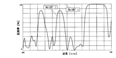
本実施例の反射率の角度特性を図5に、垂直入射光に対する反射率の波長特性を図6に、60°の入射光に対する反射率の波長特性を図7に示す。なお、以下の各図においてRsはs偏光に対する特性、Rpはp偏光に対する特性、Raはs偏光とp偏光とに対する平均的特性である。
図5に示すとおり、本実施例の反射率の角度特性は、s偏光のみに限定すると、ガラス基板の反射率の角度特性(図3参照)によく一致している。また、図6に示すとおり、本実施例は、垂直入射する可視光に対し高い透過率を有する。また、図7に示すとおり、本実施例は、60°入射する略全域の可視光に対し略100%の反射率を有する。
FIG. 5 shows the angular characteristics of the reflectance of this embodiment, FIG. 6 shows the wavelength characteristics of the reflectance with respect to normal incident light, and FIG. 7 shows the wavelength characteristics of the reflectance with respect to 60 ° incident light. In the following figures, Rs is a characteristic for s-polarized light, Rp is a characteristic for p-polarized light, and Ra is an average characteristic for s-polarized light and p-polarized light.
As shown in FIG. 5, the angular characteristic of the reflectance of the present example is in good agreement with the angular characteristic of the reflectance of the glass substrate (see FIG. 3) when limited to s-polarized light. In addition, as shown in FIG. 6, the present example has a high transmittance for vertically incident visible light. Further, as shown in FIG. 7, the present example has a reflectance of approximately 100% with respect to visible light in a substantially entire area incident at 60 °.
なお、本実施例では、基板との間にマッチング層を介在させている。マッチング層は、透過帯(反射率の低い波長領域)のリップルを低減する役割などを果たしている。
[第2実施例]
以下、誘電体光学多層膜からなる置換膜12a,13aの第2実施例を説明する。
本実施例は、液晶表示素子21の光源が偏光しているときに有効な実施例である。基本構成は例えば以下のとおりである。
In this embodiment, a matching layer is interposed between the substrate and the substrate. The matching layer plays the role of reducing ripples in the transmission band (wavelength region with low reflectance).
[Second Embodiment]
A second embodiment of the
This embodiment is an effective embodiment when the light source of the liquid
基板/(0.125H0.25L0.125H)k/基板
因みに、この構成は、一般に「長波長透過フィルタ」と呼ばれる。所定波長より長い波長の光に対する透過率が高く、所定波長より短い波長の光に対する反射率が高いという特徴がある。
最適化した結果、本実施例は以下のとおりとなった。
Substrate / (0.125H0.25L0.125H) k / substrate By the way, this configuration is generally called “long wavelength transmission filter”. There is a feature that the transmittance for light having a wavelength longer than the predetermined wavelength is high and the reflectance for light having a wavelength shorter than the predetermined wavelength is high.
As a result of optimization, the present example was as follows.
基板/(0.3H0.27L0.14H)(0.1547H0.2684L0.1547H)3(0.14H0.27L0.3H)/基板
但し、基板の屈折率は1.56、高屈折率層Hの屈折率は2.00、低屈折率層Lの屈折率は1.48、中心波長λは750nmである。高屈折率層HはZrO2、HfO5、Sc2O3、Pr2O6、Y2O3の何れかを用い、成膜条件を調整して構成した。なお、基板と低屈折率層Lは先の実施例と同じものを用いた。
Substrate / (0.3H0.27L0.14H) (0.1547H0.2684L0.1547H) 3 (0.14H0.27L0.3H) / Substrate However, the refractive index of the substrate is 1.56 and the refractive index of the high refractive index layer H is 2. .00, the refractive index of the low refractive index layer L is 1.48, and the center wavelength λ is 750 nm. The high refractive index layer H was configured by using any of ZrO 2 , HfO 5 , Sc 2 O 3 , Pr 2 O 6 , and Y 2 O 3 and adjusting the film forming conditions. The substrate and the low refractive index layer L were the same as those in the previous examples.
本実施例の反射率の角度特性を図8に、垂直入射光に対する反射率の波長特性を図9に、60°の入射光に対する反射率の波長特性を図10に示す。
図8、図9、図10に示すとおり、本実施例によれば、s偏光について第1実施例と略同様の良好な特性が得られる。
なお、本実施例は、長波長透過フィルタを基本構成とした。第1実施形態の(2)で述べた理論によると、短波長透過フィルタが適していることになるが、実在する薄膜材料の屈折率を前提に検討すると、このように、長波長透過フィルタを基本構成とした設計解が得られることもしばしばある。
FIG. 8 shows the angular characteristics of the reflectance of this embodiment, FIG. 9 shows the wavelength characteristics of the reflectance with respect to the normal incident light, and FIG. 10 shows the wavelength characteristics of the reflectance with respect to the incident light of 60 °.
As shown in FIGS. 8, 9, and 10, according to this example, good characteristics similar to those of the first example can be obtained with respect to s-polarized light.
In this embodiment, a long wavelength transmission filter is used as a basic configuration. According to the theory described in (2) of the first embodiment, a short wavelength transmission filter is suitable. However, when considering a refractive index of an existing thin film material, a long wavelength transmission filter is Often, a design solution with a basic configuration is obtained.
[第3実施例]
以下、誘電体光学多層膜からなる置換膜12a,13aの第3実施例を説明する。
本実施例は、液晶表示素子21の光源が無偏光であるときに有効な実施例である。最適化の結果、本実施例は以下のとおりとなった。
基板/(0.25H0.125L)(0.125L0.25H0.125L)4(0.125L0.25H)/基板
但し、基板の屈折率は1.75、高屈折率層Hの屈折率は2.30、低屈折率層Lの屈折率は1.48、中心波長λは1150nmである。なお、基板はSCHOTT社のN−LAF4を用いた。高屈折率層HはTiO2、Ta2O5、Nb2O5の何れかを成膜条件を調整して形成し、低屈折率層LはSiO2を成膜して形成した。
[Third embodiment]
A third embodiment of the
This embodiment is an effective embodiment when the light source of the liquid
Substrate / (0.25H0.125L) (0.125L0.25H0.125L) 4 (0.125L0.25H) / Substrate However, the refractive index of the substrate is 1.75, the refractive index of the high refractive index layer H is 2.30, low The refractive index of the refractive index layer L is 1.48, and the center wavelength λ is 1150 nm. The substrate used was N-LAF4 manufactured by SCHOTT. The high refractive index layer H was formed by adjusting any one of TiO 2 , Ta 2 O 5 , and Nb 2 O 5 while adjusting the film forming conditions, and the low refractive index layer L was formed by forming SiO 2 .
本実施例の反射率の角度特性を図11に、垂直入射光に対する反射率の波長特性を図12に、60°の入射光に対する反射率の波長特性を図13に示す。
図11、図12、図13に示すとおり、本実施例によれば、p偏光、s偏光のの双方について良好な特性が得られる。
なお、本実施例の構成をモデル化すると以下のような対称な構成となる。
FIG. 11 shows the angular characteristics of the reflectance of this embodiment, FIG. 12 shows the wavelength characteristics of the reflectance with respect to the normal incident light, and FIG. 13 shows the wavelength characteristics of the reflectance with respect to the incident light of 60 °.
As shown in FIGS. 11, 12, and 13, according to this example, good characteristics can be obtained for both p-polarized light and s-polarized light.
When the configuration of the present embodiment is modeled, the following symmetric configuration is obtained.
基板/(マッチンク゛層群I)k1・(対称層群)k2・(マッチンク゛層II)k3/基板
各層群は、低屈折率層L・高屈折率層Hを繰り返し積層してなり(LHL又はHLH)、60°の入射光に対し反射率が高まるよう設定されている。中央の層群は、垂直入射光を反射する傾向にあるため、この反射を抑える目的でマッチング層群I,IIの各層の膜厚が最適化調整されている。
Substrate / (Matching layer group I) k1 , (Symmetric layer group) k2 , (Matching layer II) k3 / Substrate Each layer group is made by repeatedly laminating low refractive index layer L and high refractive index layer H (LHL or HLH) ), And the reflectance is set to be increased with respect to incident light of 60 °. Since the central layer group tends to reflect normal incident light, the film thickness of each of the matching layer groups I and II is optimized and adjusted for the purpose of suppressing this reflection.
設計時には、光の入射角度や基板の屈折率などに応じて、このモデルの各層群の積層回数k1,k2,k3を増減したり、マッチング層群I,IIの各層の膜厚を調整したりすればよい。
また、一方の基板との関係と、他方の基板との関係とが互いに異なる場合(2つの基板の屈折率が異なったり、一方の基板との間にのみ接着剤層が介在するときなど)には、マッチング層群I,IIの積層回数及び各層の膜厚を個別に調整すればよい。
At the time of design, the number of laminations k1, k2, and k3 of each layer group of this model is increased or decreased according to the incident angle of light, the refractive index of the substrate, etc., and the film thickness of each layer of the matching layer groups I and II is adjusted. do it.
Also, when the relationship with one substrate is different from the relationship with the other substrate (when the refractive index of the two substrates is different, or when the adhesive layer is interposed only between the one substrate, etc.) In this case, the number of stacking of the matching layer groups I and II and the film thickness of each layer may be adjusted individually.
また、現在では計算機による膜厚の最適化設計や膜構成の自動合成の手法も普及している。この手法を用いた場合には、得られる設計解が上述した基本構成から若干外れることがある。しかし、それでも基本構成を一部調整したもの(基本構成の変形)とみなせる。
[第4実施例]
以下、誘電体光学多層膜からなる置換膜12a,13aの第4実施例を説明する。
At present, techniques for optimizing the film thickness by computer and automatic synthesis of the film structure are also widespread. When this method is used, the obtained design solution may slightly deviate from the basic configuration described above. However, it can still be regarded as a partial adjustment of the basic configuration (a modification of the basic configuration).
[Fourth embodiment]
Hereinafter, a fourth embodiment of the
本実施例は、液晶表示素子21の光源が偏光しているときに有効な実施例である。また、本実施例は、計算機による膜構成の自動合成の手法を適用した実施例である。本実施例の膜構成は、表1のとおりである。
This embodiment is an effective embodiment when the light source of the liquid

本実施例の反射率の角度特性を図14に、垂直入射光に対する反射率の波長特性を図15に、60°の入射光に対する反射率の波長特性を図16に示す。
図14、図15、図16に示すとおり、本実施例によれば良好な特性が得られる。特に図15に示すとおり、垂直入射光に対する透過率が特に良く改善される。
[第5実施例]
以下、誘電体光学多層膜からなる置換膜12a,13aの第5実施例を説明する。
FIG. 14 shows the angular characteristics of the reflectance of this embodiment, FIG. 15 shows the wavelength characteristics of the reflectance with respect to the normal incident light, and FIG. 16 shows the wavelength characteristics of the reflectance with respect to the incident light of 60 °.
As shown in FIGS. 14, 15, and 16, good characteristics can be obtained according to this embodiment. In particular, as shown in FIG. 15, the transmittance for vertically incident light is particularly improved.
[Fifth embodiment]
The fifth embodiment of the
本実施例は、液晶表示素子21の光源が無偏光であるときに有効な実施例である。また、本実施例は、計算機による膜構成の自動合成の手法を適用した実施例である。本実施例の膜構成は、表2のとおりである。
This embodiment is an effective embodiment when the light source of the liquid
本実施例の反射率の角度特性を図17に、垂直入射光に対する反射率の波長特性を図18に、60°の入射光に対する反射率の波長特性を図19に示す。
図17、図18、図19に示すとおり、本実施例によれば、良好な特性が得られる。特に図18、図19に示すとおり、垂直入射光に対する透過率、及び60°の入射光に対する反射率がそれぞれ改善される。
FIG. 17 shows the angular characteristics of the reflectance of this embodiment, FIG. 18 shows the wavelength characteristics of the reflectance with respect to the normal incident light, and FIG. 19 shows the wavelength characteristics of the reflectance with respect to the incident light of 60 °.
As shown in FIG. 17, FIG. 18, and FIG. 19, according to this embodiment, good characteristics can be obtained. In particular, as shown in FIGS. 18 and 19, the transmittance for vertically incident light and the reflectance for 60 ° incident light are improved.
[第2実施形態]
以下、図20、図21を参照して本発明の第2実施形態を説明する。本実施形態は、アイグラスディスプレイの実施形態である。ここでは、第1実施形態との相違点を主に説明する。
図20は、本アイグラスディスプレイの光学系部分を観察者の水平面で切断してできる概略断面図である。図20に示すように、本アイグラスディスプレイの光学系部分は、画像導入ユニット2及び1枚の基板11からなる(画像導入ユニット2は、液晶表示素子21及びレンズ22を搭載し、基板11は導入ミラー11a及びハーフミラー11bを内部に設置している。)。
[Second Embodiment]
Hereinafter, a second embodiment of the present invention will be described with reference to FIGS. This embodiment is an embodiment of an eyeglass display. Here, differences from the first embodiment will be mainly described.
FIG. 20 is a schematic cross-sectional view obtained by cutting the optical system portion of the eyeglass display along the observer's horizontal plane. As shown in FIG. 20, the optical system portion of the present eyeglass display includes an
本アイグラスディスプレイにおいては、基板11の観察者側の面と外界側の面との各々に、反射増強膜22aが密着して設けられている。
反射増強膜22aは、少なくとも置換膜12a,13aと同じ機能(エアギャップと同じ機能)を持つ。すなわち、反射増強膜22aは、基板11内を内面反射すべき表示光束L1(ここでは、入射角度60°近傍で入射する可視光)に対し反射性を示し、かつ基板11を透過すべき表示光束L1及び外界光束L2(ここでは、入射角度0°近傍で入射する可視光)に対し透過性を示す。
In the present eyeglass display, a
The
但し、反射増強膜22aが反射可能な可視光の入射角度範囲θgは、置換膜12a,13aのそれよりも拡大されており、具体的には、その入射角度範囲θgの下限は、基板11の臨界角度θc(≒40°)よりも小さく、例えば35°などに設定される(なお、入射角度範囲θgの上限は、置換膜12a,13a、空気中の基板11の単体と同じく90°近傍かつ90°未満である。)。
However, the incident angle range θg of visible light that can be reflected by the
この反射増強膜22aが設けられた基板11は、基板11が単体で空気中に存在していたときよりも、内面反射可能な表示光束11の入射角度範囲θgは、拡大される。入射角度範囲θgが拡大されれば、観察眼が観察できる画像の画角が拡大される。
なお、反射増強膜22aが反射可能な可視光の入射角度範囲θgの下限を小さくし過ぎると次のような問題が生じうる。すなわち、外界光束L2の一部が反射増強膜22aを透過できなくなって外界の視認性が悪くなったり、ハーフミラー11bで偏向された表示光束L1の一部が基板11から外部(射出瞳)へ射出できなくなってロスとなる可能性がある。このため、反射増強膜22aが反射可能な可視光の入射角度範囲θgの下限は、表示光束L1の画角や内面反射するときの入射角度を考慮した上で、0°〜θcの間の適当な値に設定される必要がある。
The incident angle range θg of the
If the lower limit of the incident angle range θg of visible light that can be reflected by the
また、このような特性を持つ反射増強膜22aは、誘電体光学多層膜やHOE(ホログラフィック・オプチカル・エレメント)などによって構成される。このうち、誘電体光学多層膜を用いた反射増強膜22aの構成の詳細は、後述する実施例にて説明する。HOEの製造方法は、第1実施形態で説明した製造方法(図4参照)と基本的に同じである。
但し、この製造方法では、図21に示すように、補助プリズム34は、感光材料35に入射するレーザ光の一方にのみ挿入されればよい(なぜなら、本実施形態の反射増強膜22aが接する2つの媒質の一方は空気だからである。)。
The
However, in this manufacturing method, as shown in FIG. 21, the
また、図21の光学系における角度θ(ホログラム感光材料35に対するレーザ光の入射角度)の値は、反射増強膜22aが反射性を示すべき光の中心入射角度範囲に設定される。
ここでも、反射増強膜22aが反射性を示すべき光の入射角度や波長は1種類ではないので、必要に応じて、角度θやレーザ光の波長を変更しながら感光材料35を多重露光することになる。
Further, the value of the angle θ (incident angle of the laser beam with respect to the hologram photosensitive material 35) in the optical system of FIG. 21 is set to the central incident angle range of the light that the
Again, since the incident angle and wavelength of light that the
また、ホログラム感光材料35として樹脂ベースの材料(樹脂シート)を用いると、大面積のHOEを低コストで製造することができる。また、HOEが樹脂シートであると、HOEをアイグラスディスプレイの基板11に密着させる際に貼付するだけで済むため、低コスト・大量生産の面で実用価値が高い。
また、本実施形態の反射増強膜22aには、金属膜や半導体膜などからなる光学多層膜が用いられてもよい。但し、そのような光学多層膜よりも誘電体光学多層膜の方が、光の吸収が少ないため、好適である。
Further, when a resin-based material (resin sheet) is used as the hologram
In addition, an optical multilayer film made of a metal film, a semiconductor film, or the like may be used for the
以上の各光学機能部(誘電体光学多層膜、HOE、その他の光学多層膜)は、アイグラスディスプレイの仕様やコストなどに応じて反射増強膜22aとして選択使用されることが望ましい。
[第6実施例]
以下、第6実施例を説明する。本実施例は、第2実施形態のアイグラスディスプレイの反射増強膜22aとして好適な誘電体光学多層膜の実施例である。
Each of the above optical function sections (dielectric optical multilayer film, HOE, and other optical multilayer films) is desirably selected and used as the
[Sixth embodiment]
The sixth embodiment will be described below. This example is an example of a dielectric optical multilayer film suitable as the
本実施例では、アイグラスディスプレイの液晶表示素子21の光源が発光スペクトルを有しており(R色,G色,B色それぞれにピークを有しており)、かつ、液晶表示素子21の光源が偏光していることを前提とした。また、本実施例では、計算機による膜構成の自動合成の手法を適用した。
本実施例の誘電体光学多層膜の膜構成は、表3のとおりである。
In the present embodiment, the light source of the liquid
Table 3 shows the film configuration of the dielectric optical multilayer film of this example.
図22は、本実施例の誘電体光学多層膜の小入射角度の光(入射角度0°〜20°)に対する反射率の波長特性である。図22において、Ra(0°),Ra(5°),Ra(10°),Ra(15°),Ra(20°)は、それぞれ入射角度0°,5°,10°,15°,20°の入射光に対する反射率(何れも入射光のs偏光成分に対する反射率とp偏光成分に対する反射率との平均値)である。 FIG. 22 is a wavelength characteristic of reflectance with respect to light with a small incident angle (incidence angle of 0 ° to 20 °) of the dielectric optical multilayer film of this example. In FIG. 22, Ra (0 °), Ra (5 °), Ra (10 °), Ra (15 °), and Ra (20 °) are incident angles of 0 °, 5 °, 10 °, 15 °, It is the reflectance for incident light at 20 ° (both are average values of the reflectance for the s-polarized component and the reflectance for the p-polarized component of the incident light).
図22に明らかなとおり、本実施例の誘電体光学多層膜は、入射角度0°〜20°の入射光であれば、可視光域の略全域に亘り80%以上の透過性を示す。
図23は、本実施例の誘電体光学多層膜の大入射角度の光(入射角度35°,40°)に対する反射率の波長特性である。図23において、Rs(35°),Rs(40°)は、それぞれ入射角度35°,40°の光に対する反射率(何れも入射光のs偏光成分に対する反射率)である。
As is clear from FIG. 22, the dielectric optical multilayer film of the present example exhibits a transmittance of 80% or more over substantially the entire visible light region when the incident light has an incident angle of 0 ° to 20 °.
FIG. 23 shows the wavelength characteristics of the reflectance with respect to light with a large incident angle (incidence angles of 35 ° and 40 °) of the dielectric optical multilayer film of this example. In FIG. 23, Rs (35 °) and Rs (40 °) are reflectivities with respect to light having incident angles of 35 ° and 40 °, respectively (both reflectivities with respect to the s-polarized component of incident light).
図23に明らかなとおり、本実施例の誘電体光学多層膜は、入射角度40°のs偏光した光であれば、可視光域の全域に亘り略100%の反射性を示す。また、入射角度35°のs偏光した光であれば、可視光域のR色,G色,B色の各成分(460,520,633nm)に対しそれぞれ80%以上の反射性を示す。
図24は、本実施例の誘電体光学多層膜の各波長の光に対する反射率の角度特性である。図24において、Rs(633nm),Rs(520nm),Rs(460nm)は、それぞれ波長633nm,520nm,460nmの光(R色,G色,B色)に対する反射率(何れも入射光のs偏光成分に対する反射率)である。
As is apparent from FIG. 23, the dielectric optical multilayer film of the present example exhibits approximately 100% reflectivity over the entire visible light region as long as it is s-polarized light having an incident angle of 40 °. In addition, s-polarized light having an incident angle of 35 ° exhibits a reflectivity of 80% or more for each of R, G, and B components (460, 520, and 633 nm) in the visible light range.
FIG. 24 shows the angle characteristics of the reflectance with respect to light of each wavelength of the dielectric optical multilayer film of this example. In FIG. 24, Rs (633 nm), Rs (520 nm), and Rs (460 nm) are reflectivities for light (R color, G color, and B color) having wavelengths of 633 nm, 520 nm, and 460 nm, respectively (all are s-polarized light of incident light). Reflectance of component).
図24に明らかなとり、本実施例の誘電体光学多層膜は、可視光域のR色,G色,B色の各成分の光であれば、35°以上の入射角度で80%以上の反射性を示す。
以上、本実施例の誘電体光学多層膜が反射性を示す可視光(ここではs偏光したR色,G色,B色の光)の入射角度範囲θgの下限は、35°である。これは、本実施例で想定した基板11(屈折率1.60)の臨界角度θc=38.7°よりも小さい。
As is apparent from FIG. 24, the dielectric optical multilayer film of the present example has a reflection of 80% or more at an incident angle of 35 ° or more if it is light of each component of R color, G color, and B color in the visible light range. Showing gender.
As described above, the lower limit of the incident angle range θg of visible light (here, s-polarized R color, G color, and B color light) in which the dielectric optical multilayer film of the present embodiment exhibits reflectivity is 35 °. This is smaller than the critical angle θ c = 38.7 ° of the substrate 11 (refractive index 1.60) assumed in this example.
したがって、本実施例の誘電体光学多層膜を反射増強膜22aとして用いたアイグラスディスプレイでは、基板11を内面反射する表示光束L1の入射角度範囲θgの下限は、臨界角度θc=38.7°から35°へと3.7°も引き下げられる。
その結果、アイグラスディスプレイは、入射角度範囲θg=35°〜65°の表示光束L1、つまり画角30°の表示光束L1を伝送することができる。
Therefore, in the eyeglass display using the dielectric optical multilayer film of this embodiment as the
As a result, the eyeglass display can transmit the display light beam L1 having an incident angle range θg = 35 ° to 65 °, that is, the display light beam L1 having an angle of view of 30 °.
また、図22に示したとおり、本実施例の誘電体光学多層膜は、小入射角度の光(0°〜20°)の可視光に対する透過率が高いので、アイグラスディスプレイの外界の視認性は確実に保たれ、また、基板11から射出瞳へ入射する表示光束L1のロスも無い。
[第3実施形態]
以下、図25を参照して本発明の第3実施形態を説明する。本実施形態は、アイグラスディスプレイの実施形態である。ここでは、第1実施形態との相違点を主に説明する。
Further, as shown in FIG. 22, the dielectric optical multilayer film of the present example has a high transmittance for visible light of light with a small incident angle (0 ° to 20 °), so that the visibility of the outside of the eyeglass display is visible. Is reliably maintained, and there is no loss of the display light beam L1 incident on the exit pupil from the
[Third Embodiment]
Hereinafter, a third embodiment of the present invention will be described with reference to FIG. This embodiment is an embodiment of an eyeglass display. Here, differences from the first embodiment will be mainly described.
図25は、本アイグラスディスプレイの光学系部分を観察者の水平面で切断してできる概略断面図である。図25に示すように、本アイグラスディスプレイは、第1実施形態のアイグラスディスプレイ(図2参照)において、置換膜12a,13aの代わりに、それぞれ反射増強膜22aを備えたものである。
この反射増強膜22aは、第2実施形態のそれと同様の機能を持つ。すなわち、反射増強膜22aが反射性を示す可視光の入射角度範囲θgの下限は、基板11の臨界角度θcよりも引き下げられている。
FIG. 25 is a schematic cross-sectional view obtained by cutting the optical system portion of the eyeglass display along the observer's horizontal plane. As shown in FIG. 25, the present eyeglass display includes a
This
したがって、本アイグラスディスプレイは、第1実施形態と同様に視度補正の効果が得られると共に、第2実施形態と同様に画角拡大の効果が得られる。
なお、この反射増強膜22aをHOEによって構成する場合の製造方法は、第1実施形態で説明した製造方法(図4参照)と同じである。
但し、図4の光学系における角度θ(ホログラム感光材料35に対するレーザ光の入射角度)の値は、反射増強膜22aが反射性を示すべき光の中心入射角度範囲に設定される。
Therefore, this eyeglass display can obtain the effect of diopter correction as in the first embodiment and the effect of widening the angle of view as in the second embodiment.
Note that the manufacturing method in the case where the
However, the value of the angle θ (incident angle of the laser beam with respect to the hologram photosensitive material 35) in the optical system of FIG. 4 is set to the central incident angle range of the light that the
ここでも、反射増強膜22aが反射性を示すべき光の入射角度や波長は1種類ではないので、必要に応じて、角度θやレーザ光の波長を変更しながら感光材料35を多重露光することになる。
[第7実施例]
以下、第7実施例を説明する。本実施例は、第3実施形態のアイグラスディスプレイの反射増強膜22aとして好適な誘電体光学多層膜の実施例である。
Again, since the incident angle and wavelength of light that the
[Seventh embodiment]
The seventh embodiment will be described below. This example is an example of a dielectric optical multilayer film suitable as the
本実施例では、アイグラスディスプレイの液晶表示素子21の光源が偏光していることを前提とした。また、本実施例では、計算機による膜構成の自動合成の手法を適用した。
本実施例の誘電体光学多層膜の膜構成は、表4のとおりである。
In this embodiment, it is assumed that the light source of the liquid
Table 4 shows the film configuration of the dielectric optical multilayer film of this example.
図26は、本実施例の誘電体光学多層膜の小入射角度の光(入射角度0°〜20°)に対する反射率の波長特性である。図26において、Ra(0°),Ra(10°),Ra(20°)は、それぞれ入射角度0°,10°,20°の入射光に対する反射率(何れも入射光のs偏光成分に対する反射率とp偏光成分に対する反射率との平均値)である。
図26に明らかなとおり、本実施例の誘電体光学多層膜は、入射角度0°〜20°の入射光であれば、可視光域の略全域に亘り70%以上の透過性を示す。
FIG. 26 shows the wavelength characteristics of the reflectance with respect to light with a small incident angle (incident angle of 0 ° to 20 °) in the dielectric optical multilayer film of this example. In FIG. 26, Ra (0 °), Ra (10 °), and Ra (20 °) are reflectivities with respect to incident light at incident angles of 0 °, 10 °, and 20 °, respectively (all with respect to the s-polarized component of the incident light). The average value of the reflectance and the reflectance for the p-polarized component).
As is apparent from FIG. 26, the dielectric optical multilayer film of the present example exhibits a transmittance of 70% or more over substantially the entire visible light region when the incident light has an incident angle of 0 ° to 20 °.
図27は、本実施例の誘電体光学多層膜の大入射角度の光(入射角度35°〜50°)に対する反射率の波長特性である。図27において、Rs(35°),Rs(40°),Rs(50°)は、それぞれ入射角度35°,40°,50°の入射光に対する反射率(何れも入射光のs偏光成分に対する反射率)である。
図27に明らかなとおり、本実施例の誘電体光学多層膜は、入射角度35°〜50°のs偏光した光であれば、可視光域の略全域に亘り65%以上の反射性を示す。
FIG. 27 shows the wavelength characteristics of the reflectance with respect to light having a large incident angle (incident angle of 35 ° to 50 °) in the dielectric optical multilayer film of this example. In FIG. 27, Rs (35 °), Rs (40 °), and Rs (50 °) are reflectivities with respect to incident light at incident angles of 35 °, 40 °, and 50 °, respectively (all with respect to the s-polarized component of the incident light). Reflectance).
As is clear from FIG. 27, the dielectric optical multilayer film of the present example exhibits a reflectivity of 65% or more over substantially the entire visible light region as long as it is s-polarized light having an incident angle of 35 ° to 50 °. .
図28は、本実施例の誘電体光学多層膜の各波長の光に対する反射率の角度特性である。図28において、Rs(633nm),Rs(520nm),Rs(460nm)は、それぞれ波長633nm,520nm,460nmの光(R色,G色,B色)に対する反射率(何れも入射光のs偏光成分に対する反射率)である。
図28に明らかなとおり、本実施例の誘電体光学多層膜は、可視光域のR色,G色,B色の各成分の光であれば、35°以上の入射角度で65%以上の反射性を示す。
FIG. 28 shows the angle characteristics of the reflectance with respect to light of each wavelength of the dielectric optical multilayer film of this example. In FIG. 28, Rs (633 nm), Rs (520 nm), and Rs (460 nm) are reflectivities with respect to light (R color, G color, and B color) having wavelengths of 633 nm, 520 nm, and 460 nm, respectively (s polarization of incident light). Reflectance of component).
As is apparent from FIG. 28, the dielectric optical multilayer film of the present example has a light intensity of 65% or more at an incident angle of 35 [deg.] Or more for light of R, G, and B colors in the visible light range. Shows reflectivity.
つまり、本実施例の誘電体多層膜が反射性を示す可視光(ここではs偏光した波長633nm,520nm,460nmの光)の入射角度範囲θgの下限は、35°である。これは、本実施例で想定した基板11(屈折率1.56)の臨界角度θc=39.9°よりも小さい。
したがって、本実施例の誘電体光学多層膜を反射増強膜22aとして用いたアイグラスディスプレイでは、基板11を内面反射する表示光束11の入射角度範囲θgの下限は、臨界角度θc=39.9°から35°へと4.9°も引き下げられる。
That is, the lower limit of the incident angle range θg of visible light (here, s-polarized light with wavelengths of 633 nm, 520 nm, and 460 nm) in which the dielectric multilayer film of this example exhibits reflectivity is 35 °. This is smaller than the critical angle θ c = 39.9 ° of the substrate 11 (refractive index 1.56) assumed in this example.
Therefore, in the eyeglass display using the dielectric optical multilayer film of this embodiment as the
また、図26に示したとおり、本実施例の誘電体光学多層膜は、小入射角度の光(0°〜20°)の可視光に対する透過率が高いので、アイグラスディスプレイの外界の視認性は保たれ、また、基板11から射出瞳へ入射する表示光束L1のロスも無い。
[第4実施形態]
以下、図29を参照して本発明の第4実施形態を説明する。本実施形態は、上述した反射増強膜を、射出瞳の大きいタイプのアイグラスディスプレイに適用したものである。
In addition, as shown in FIG. 26, the dielectric optical multilayer film of the present example has a high transmittance for visible light of light with a small incident angle (0 ° to 20 °). Is maintained, and there is no loss of the display light beam L1 incident on the exit pupil from the
[Fourth Embodiment]
The fourth embodiment of the present invention will be described below with reference to FIG. In this embodiment, the above-described reflection enhancement film is applied to an eyeglass display of a type having a large exit pupil.
図29は、本実施形態のアイグラスディスプレイの光学系部分を観察者の水平面で切断してできる概略断面図である。図29に示すように、本アイグラスディスプレイは、表示光束L1を内面反射する基板11中に、互いに平行な複数のハーフミラー11bを配置している。これらの複数のハーフミラー11bのそれぞれは、基板11を内面反射する表示光束L1のうち所定角度範囲で入射したものを反射し、基板11の外部に射出瞳を形成する。この射出瞳のサイズは、ハーフミラー11bが複数化された分だけ大きい。このように射出瞳が大きいと、観察眼の瞳の位置の自由度が高まる点で有利である。
FIG. 29 is a schematic cross-sectional view obtained by cutting the optical system portion of the eyeglass display of the present embodiment along the observer's horizontal plane. As shown in FIG. 29, in the present eyeglass display, a plurality of half mirrors 11b parallel to each other are arranged in a
このアイグラスディスプレイにおいて、反射増強膜22aは、基板11の観察者側の面、外界側の面のそれぞれに密着して形成される。この反射増強膜22aは、上述した実施形態におけるそれと同様に、基板11を内面反射可能な表示光束L1の入射角度範囲θgを拡大する。よって、このアイグラスディスプレイの画角も拡大される。
[第5実施形態]
以下、図30を参照して本発明の第5実施形態を説明する。本実施形態は、上述した反射増強膜を、射出瞳の大きい別のタイプのアイグラスディスプレイに適用したものである。
In this eyeglass display, the
[Fifth Embodiment]
Hereinafter, a fifth embodiment of the present invention will be described with reference to FIG. In this embodiment, the above-described reflection enhancing film is applied to another type of eyeglass display having a large exit pupil.
図30は、本実施形態のアイグラスディスプレイの光学系部分を観察者の水平面で切断してできる概略断面図である。図30に示すように、本アイグラスディスプレイは、大きな射出瞳を形成するための複数のハーフミラーを、基板11の外部に配置している。それら複数のハーフミラーは、外界側又は観察者側(図30では外界側)に配置された基板12の内部に設けられる。また、複数のハーフミラーは、互いに平行な複数のハーフミラー11bLと、それと姿勢の異なる互いに平行な複数のハーフミラー11bRとの2種類からなる。
FIG. 30 is a schematic cross-sectional view obtained by cutting the optical system portion of the eyeglass display of the present embodiment along the observer's horizontal plane. As shown in FIG. 30, in the present eyeglass display, a plurality of half mirrors for forming a large exit pupil are arranged outside the
また、基板11の内部には、基板11に入射した表示光束L1を内面反射可能な角度に偏向するための導入ミラー11aと、基板11を内面反射した表示光束11を折り返す折り返しミラー11cとが設けられる。この折り返しミラー11cの作用により、本アイグラスディスプレイの表示光束L1は、基板11を内面反射しながら往復する。
そして、複数のハーフミラーのうち一方のハーフミラー11bLの姿勢は、往路進行中の表示光束L1を観察者側に偏向するように設定され、他方のハーフミラー11bRの姿勢は、復路進行中の表示光束L1を観察者側に偏向するように設定される。したがって、複数のハーフミラー11bL,11bRの全体は、屋根型のハーフミラーを密に並べた構成となる。
In addition, inside the
The posture of one
このアイグラスディスプレイにおいて、反射増強膜は、基板12と基板11との間と、基板11の観察者側の面との各々に密着して設けられる。
このうち、基板11の観察者側の反射増強膜22aは、上述した実施形態のそれと同じであり、基板11を内面反射する表示光束L1に対し反射性を示す。
一方、基板11の外界側の反射増強膜22a’は、上述した実施形態のそれとは若干異なり、基板11を内面反射する表示光束L1に対し半透過性を示す。
In this eyeglass display, the reflection enhancing film is provided in close contact with each of the space between the
Among these, the
On the other hand, the
すなわち、反射増強膜22a’は、基板11を透過すべき表示光束L1及び外界光束L2(ここでは、入射角度0°近傍で入射する可視光)に対し透過性(全透過性)を示すと共に、基板11内を内面反射すべき表示光束L1(ここでは、入射角度60°近傍で入射する可視光)に対し半透過性を示す。そして、その半透過性を示す入射角度範囲の下限は、基板11の臨界角度θcよりも小さい値に設定される。
That is, the
この反射増強膜22a’の半透過性により、基板11内を往復する表示光束L1は、一定の割合で基板12の側へ浸入することになる。その浸入した表示光束L1は、基板12内の複数のハーフミラー11bL,11bRによって観察者側へと偏向される。そして、複数のハーフミラー11bL,11bRにより偏向した表示光束L1は、反射増強膜22a’、基板11及び反射増強膜22aを透過して、大きな射出瞳を形成する。
Due to the translucency of the
さらに、以上の反射増強膜22a,22a’は、上述した実施形態のそれと同様に、内面反射可能な表示光束L1の入射角度範囲を拡大する。したがって、このアイグラスディスプレイの画角も、拡大される。
なお、本アイグラスディスプレイにおいては、折り返しミラー11cが設けられると共に、ハーフミラーが2種類設けられたが、折り返しミラー11cと一方のハーフミラー11bRとを省略することもできる。但し、それらを備えた方が、射出瞳内の光量が均一化されるので好ましい。
Further, the above-described
In the present eyeglass display, with
[第6実施形態]
以下、図31を参照して本発明の第6実施形態を説明する。本実施形態は、上述した反射増強膜を、射出瞳のさらに大きいタイプのアイグラスディスプレイに適用したものである。
図31は、本実施形態のアイグラスディスプレイの光学系部分の分解図である。図31に示すように、本アイグラスディスプレイは、第5実施形態のアイグラスディスプレイと同じ原理が適用され、かつ、観察者から見て縦横の2方向に亘って射出瞳を拡大したものである。また、このアイグラスディスプレイには、観察眼の視度補正の機能も付加されている。
[Sixth Embodiment]
The sixth embodiment of the present invention will be described below with reference to FIG. In this embodiment, the above-described reflection enhancement film is applied to an eyeglass display of a type having a larger exit pupil.
FIG. 31 is an exploded view of the optical system portion of the eyeglass display of the present embodiment. As shown in FIG. 31, this eyeglass display is obtained by applying the same principle as the eyeglass display of the fifth embodiment and enlarging the exit pupil in two vertical and horizontal directions as viewed from the observer. . The eyeglass display also has a function of correcting the diopter of the observation eye.
図31において、画像導入ユニット2から射出した表示光束L1は、最初に基板11’に入射する。基板11’は、基板12’と共にその表示光束L1を導光し、観察者から見た縦方向に亘って表示光束L1の径を拡大する。その表示光束L1は、基板11に入射する。基板11は、基板12と共にその表示光束L1を導光し、観察眼から見た横方向に亘って表示光束L1の径を拡大する。その表示光束L1は、観察眼の近傍に射出瞳を形成する。
In FIG. 31, the display light beam L1 emitted from the
また、基板11の観察者側には基板13が設けられており、基板13の観察眼側の面と、基板12の外界側の面との光学的パワーにより、観察眼の外界に対する視度補正が図られる。
基板11’,12’からなる第1光学系と、基板11,12からなる第2光学系とのそれぞれには、第5実施形態の基板11,12と同じ原理が適用されている。また、第1光学系と第2光学系との間で、各光学面の配置方向は90°回転している。
Further, a
The same principle as that of the
すなわち、基板11’の内部に符号11a’で示すのは、基板11’に入射した表示光束L1を内面反射可能な角度に偏向する導入ミラーであり、符号11c’で示すのは、基板11’を内面反射した表示光束L1を折り返す折り返しミラーである。基板12’において符号12a’で示すのは、複数の屋根型のハーフミラーを密に並べたものである(詳細は、図30参照)。
That is, what is indicated by reference numeral 11a ′ inside the
また、基板11の内部に符号11aで示すのは、基板11に入射した表示光束L1を内面反射可能な角度に偏向する導入ミラーであり、符号11cで示すのは、基板11を内面反射した表示光束L1を折り返す折り返しミラーである。基板12において符号12aで示すのは、複数の屋根型のハーフミラーを密に並べたものである(詳細は、図30参照)。
以上のアイグラスディスプレイにおいて、反射増強膜が設けられる箇所は、基板11’と基板12’との間、基板11’と基板13’との間、基板11と基板12との間、基板11と基板13との間の各々である。
但し、基板11’と基板12’との間に設けられる反射増強膜の特性は、基板11’を内面反射する表示光束L1を一定の割合で基板12’に透過させるものである必要がある。その特性は、第5実施形態の反射増強膜22a’の特性と同じである。
In the above eyeglass display, the location where the reflection enhancing film is provided is between the
However, the characteristic of the reflection enhancement film provided between the
また、基板11と基板12との間に設けられる反射増強膜の特性も、基板11を内面反射する表示光束L1を一定の割合で基板12に透過させるものである必要がある。その特性は、第5実施形態の反射増強膜22a’の特性と同じである。
以上の反射増強膜は、基板11’を内面反射可能な表示光束L1の入射角度範囲と、基板11を内面反射可能な表示光束L1の入射角度範囲とをそれぞれ拡大する。しかも、基板11’における拡大方向と基板11における拡大方向とは、90°回転している。
In addition, the characteristic of the reflection enhancement film provided between the
The above-described reflection enhancement film expands the incident angle range of the display light beam L1 capable of reflecting the
したがって、本アイグラスディスプレイでは、縦方向の画角と横方向の画角との双方が拡大される。
[第7実施形態]
以下、図32を参照して本発明の第7実施形態を説明する。本実施形態は、上述した反射増強膜を、内面反射に供される面の多いタイプのアイグラスディスプレイに適用したものである。
Therefore, in the present eyeglass display, both the vertical field angle and the horizontal field angle are enlarged.
[Seventh Embodiment]
The seventh embodiment of the present invention will be described below with reference to FIG. In this embodiment, the above-described reflection enhancement film is applied to an eyeglass display of a type having many surfaces subjected to internal reflection.
図32(a)は、本アイグラスディスプレイの光学系部分の概略斜視図である。図32(b)は、その光学系部分を観察者の水平面(図32(a)のZX平面)で切断してできる概略断面図である。図32(c)は、その光学系部分を観察者の前面(図32(a)のYX平面)で切断してできる概略断面図である。図32(d)は、本アイグラスディスプレイの画角を説明する図である。 FIG. 32A is a schematic perspective view of an optical system portion of the present eyeglass display. FIG. 32B is a schematic cross-sectional view obtained by cutting the optical system portion along the observer's horizontal plane (ZX plane in FIG. 32A). FIG. 32C is a schematic cross-sectional view obtained by cutting the optical system portion at the front of the observer (YX plane in FIG. 32A). FIG. 32D is a diagram for explaining the angle of view of the present eyeglass display.
図32(a),(b),(c)に示すように、本アイグラスディスプレイは、導入ミラー11a及び複数のハーフミラー11bの配置箇所や姿勢を調整し、基板11のうち内面反射に供される面を、観察者側の面、外界側の面、及び両者に挟まれた2面の合計4面としている。なお、この4面は何れも平面である。
図32(d)には、本アイグラスディスプレイの観察眼から見た画像の2方向の画角θb-air,θa-airを示した。
As shown in FIGS. 32A, 32B, and 32C, this eyeglass display adjusts the location and orientation of the
FIG. 32 (d) shows two angles of view θb −air and θa −air of the image viewed from the observation eye of the present eyeglass display.
このうち、画角θb-airは、図32(b)に示したように、基板11の観察者側の面と外界側の面との2面が内面反射可能な表示光束L1の角度範囲θb-gによって決まる。
また、画角θa-airは、図32(c)に示したように、基板11の他の2面が内面反射可能な表示光束L1の角度範囲θa-gによって決まる。
これを式にすると、以下のとおりである。
Of these, the angle of view θb -air is the angle range θb of the display light beam L1 in which the two surfaces of the
Further , as shown in FIG. 32C , the angle of view θa- air is determined by the angle range θa- g of the display light beam L1 in which the other two surfaces of the
This can be expressed as follows.
θa-air=sin-1[ngsinθa-g]
θb-air=sin-1[ngsinθb-g]
つまり、画角θb-air,θa-airは、基板11を内面反射可能な表示光束L1の角度範囲θa-g,θb-gのそれぞれが大きいほど、大きくなる。
そして、本アイグラスディスプレイにおいて、反射増強膜が設けられる箇所は、基板11のうち、内面反射に供される4面である。図32(b),(c)において符号22aで示すのが、反射増強膜である。この反射増強膜22aの特性は、上述した実施形態における反射増強膜22aのそれと同様であり、反射増強膜22aが反射性を示す可視光の入射角度範囲の下限は、基板11の臨界角度θcよりも引き下げられている。
θa -air = sin -1 [n g sinθa -g]
θb -air = sin -1 [n g sinθb -g]
That is, the angle of view θb −air and θa −air become larger as the angle ranges θa −g and θb −g of the display light beam L1 that can reflect the
And in this eyeglass display, the locations where the reflection enhancing film is provided are four surfaces of the
したがって、基板11を内面反射可能な表示光束L1の角度範囲θb-g,θa-g(図32(b),(c))は、それぞれ拡大される。その結果、本アイグラスディスプレイの画角θb-air,θa-air(図32(d))も、それぞれ拡大される。
なお、図32(c)に示した2つの反射増強膜22aは、観察眼に正対しないので、外界光束を透過する必要が無い。
Therefore, the angle ranges θb −g and θa −g (FIGS. 32B and 32C) of the display light beam L1 that can reflect the
Note that the two
よって、仮に、液晶表示素子21の縦横比が1:1でないときには、そのうち長い方の画角が画角θa-airに対応するように液晶表示素子21を配置するとよい。
なお、本アイグラスディスプレイの基板11は、断面が長方形の柱状の基体であるが、断面が三角形の柱状の基体や、断面が平行四辺形の柱状の基体や、断面が5角形の柱状の基体など、断面の異なる他の柱状の基体を用いることもできる。
Therefore, if the aspect ratio of the liquid
The
上記実施形態では、アイグラスディスプレイしか説明しなかったが、カメラ、双眼鏡、顕微鏡、望遠鏡のファインダなどにも同様に本発明は適用可能である。 In the above embodiment, only the eyeglass display has been described. However, the present invention is also applicable to a camera, binoculars, a microscope, a telescope finder, and the like.
1:画像表示光学系,2:画像導入ユニット,11及び12及び13:基板,12a及び13a:置換膜,22a及び22a’:反射増強膜,22:レンズ,21:液晶表示素子,11a:導入ミラー,11b:ハーフミラー,11c:折り返しミラー
1: image display optical system, 2: image introduction unit, 11 and 12 and 13: substrate, 12a and 13a: substitution film, 22a and 22a ′: reflection enhancement film, 22: lens, 21: liquid crystal display element, 11a: introduction Mirror, 11b: Half mirror, 11c: Folding mirror
Claims (8)
前記伝搬する前記所定の光束が到達可能な前記基板の面上に密着して設けられ、その所定の光束を反射すると共にその面に到来する外界光束を透過する干渉作用を有した光学機能部とを備え、
前記光学機能部は、
光学多層膜からなる
ことを特徴とする光学素子。 A substrate through which a predetermined luminous flux can propagate;
An optical function unit provided in close contact with the surface of the substrate where the predetermined light beam that propagates is reachable, and having an interference function of reflecting the predetermined light beam and transmitting an external light beam arriving on the surface; With
The optical function unit is
An optical element comprising an optical multilayer film.
前記光学多層膜は、
誘電体光学多層膜である
ことを特徴とする光学素子。 The optical element according to claim 1,
The optical multilayer film is
An optical element characterized by being a dielectric optical multilayer film.
前記誘電体光学多層膜は、
互いに屈折率の異なる少なくとも2種類の層を積層してなる
ことを特徴とする光学素子。 The optical element according to claim 2,
The dielectric optical multilayer film is:
An optical element comprising at least two types of layers having different refractive indexes.
前記光学機能部は、
特定の偏光方位の前記所定の光束を反射し、かつ他の偏光方位の光束を透過する性質を有している
ことを特徴とする光学素子。 In the optical element according to any one of claims 1 to 3 ,
The optical function unit is
An optical element characterized by reflecting the predetermined light beam having a specific polarization direction and transmitting a light beam having another polarization direction.
前記光学機能部は、
前記基板と空気との屈折率によって決定する、基板内部の光束が全反射する条件の臨界角又は前記臨界角よりも大きな入射角度で前記面に到達する前記所定の光束を、所望の反射特性で反射する性質を有している
ことを特徴とする光学素子。 In the optical element according to any one of claims 1 to 4 ,
The optical function unit is
The predetermined luminous flux reaching the surface at a critical angle under a condition where the luminous flux inside the substrate is totally reflected, or an incident angle larger than the critical angle, determined by the refractive index of the substrate and air, with a desired reflection characteristic. An optical element characterized by having a reflective property.
前記光学素子に設けられ、その光学素子の内部を伝搬した前記表示光束を所定方向に反射すると共に前記外界光束を透過するコンバイナと
を備えたことを特徴とするコンバイナ光学系。 The optical element according to any one of claims 1 to 5 , wherein a display light beam emitted from the image display element is propagated inside;
A combiner optical system comprising: a combiner that is provided in the optical element and reflects the display light beam propagating through the optical element in a predetermined direction and transmits the external light beam.
前記光学機能部に密着して設けられた視度補正用の屈折レンズ
を備えたことを特徴とするコンバイナ光学系。 The combiner optical system according to claim 6 ,
A combiner optical system comprising a dioptric lens for diopter correction provided in close contact with the optical function unit.
請求項6又は請求項7に記載のコンバイナ光学系と
を備えたことを特徴とする情報表示装置。 An image display element;
Information display device characterized by comprising a combiner optical system according to claim 6 or claim 7.
Priority Applications (1)
| Application Number | Priority Date | Filing Date | Title |
|---|---|---|---|
| JP2005106174A JP4609160B2 (en) | 2004-05-17 | 2005-04-01 | Optical element, combiner optical system, and information display device |
Applications Claiming Priority (2)
| Application Number | Priority Date | Filing Date | Title |
|---|---|---|---|
| JP2004146579 | 2004-05-17 | ||
| JP2005106174A JP4609160B2 (en) | 2004-05-17 | 2005-04-01 | Optical element, combiner optical system, and information display device |
Publications (2)
| Publication Number | Publication Date |
|---|---|
| JP2006003872A JP2006003872A (en) | 2006-01-05 |
| JP4609160B2 true JP4609160B2 (en) | 2011-01-12 |
Family
ID=35772277
Family Applications (1)
| Application Number | Title | Priority Date | Filing Date |
|---|---|---|---|
| JP2005106174A Expired - Fee Related JP4609160B2 (en) | 2004-05-17 | 2005-04-01 | Optical element, combiner optical system, and information display device |
Country Status (1)
| Country | Link |
|---|---|
| JP (1) | JP4609160B2 (en) |
Cited By (1)
| Publication number | Priority date | Publication date | Assignee | Title |
|---|---|---|---|---|
| US10466482B2 (en) | 2016-09-21 | 2019-11-05 | Seiko Epson Corporation | Optical element and display device |
Families Citing this family (50)
| Publication number | Priority date | Publication date | Assignee | Title |
|---|---|---|---|---|
| FR2873212B1 (en) * | 2004-07-16 | 2011-06-10 | Essilor Int | OPTHALMIC LENS FOR REALIZING AN OPTICAL DISPLAY |
| US10073264B2 (en) | 2007-08-03 | 2018-09-11 | Lumus Ltd. | Substrate-guide optical device |
| US10048499B2 (en) | 2005-11-08 | 2018-08-14 | Lumus Ltd. | Polarizing optical system |
| FR2938934B1 (en) * | 2008-11-25 | 2017-07-07 | Essilor Int - Cie Generale D'optique | GLASSES OF EYEWEAR PROVIDING OPHTHALMIC VISION AND ADDITIONAL VISION |
| JP5315974B2 (en) * | 2008-12-18 | 2013-10-16 | コニカミノルタ株式会社 | Optical path combiner, video display device, and head mounted display |
| WO2011024291A1 (en) * | 2009-08-28 | 2011-03-03 | 株式会社島津製作所 | Display device |
| JP2011118142A (en) * | 2009-12-03 | 2011-06-16 | Stanley Electric Co Ltd | Display device and method for manufacturing the same |
| CN102741729B (en) * | 2010-02-04 | 2014-07-16 | 埃西勒国际通用光学公司 | A method of manufacturing a lens for providing an optical display |
| JP5901192B2 (en) * | 2011-09-13 | 2016-04-06 | オリンパス株式会社 | Optical mechanism |
| JP6225474B2 (en) | 2013-05-14 | 2017-11-08 | セイコーエプソン株式会社 | Display device |
| DE102013219623B4 (en) * | 2013-09-27 | 2015-05-21 | Carl Zeiss Ag | Spectacle lens for a display device which can be placed on the head of a user and generates an image, and a display device with such a spectacle lens |
| DE102013219626B4 (en) * | 2013-09-27 | 2015-05-21 | Carl Zeiss Ag | Spectacle lens for a display device to be placed on the head of a user and an image-generating display device and display device with such a spectacle lens |
| CN110542938B (en) * | 2013-11-27 | 2023-04-18 | 奇跃公司 | Virtual and augmented reality systems and methods |
| JP5851535B2 (en) * | 2014-01-27 | 2016-02-03 | オリンパス株式会社 | Display device |
| EP3120170A1 (en) * | 2014-03-18 | 2017-01-25 | 3M Innovative Properties Company | Low profile image combiner for near-eye displays |
| DE102014207500B3 (en) * | 2014-04-17 | 2015-05-07 | Carl Zeiss Ag | Spectacle lens for a display device that can be placed on the head of a user and forms an image |
| DE102014207499B4 (en) * | 2014-04-17 | 2017-02-09 | Carl Zeiss Jena Gmbh | Spectacle lens for a display device that can be placed on the head of a user and forms an image |
| IL232197B (en) | 2014-04-23 | 2018-04-30 | Lumus Ltd | Compact head-mounted display system |
| JP6648041B2 (en) | 2014-05-30 | 2020-02-14 | マジック リープ, インコーポレイテッドMagic Leap,Inc. | Method and system for displaying stereoscopic view using freeform optical system with addressable focus for virtual and augmented reality |
| IL235642B (en) | 2014-11-11 | 2021-08-31 | Lumus Ltd | Compact head-mounted display system protected by a hyperfine structure |
| IL236490B (en) * | 2014-12-25 | 2021-10-31 | Lumus Ltd | Optical component on a conductive substrate |
| EP3248051B1 (en) | 2015-01-22 | 2020-09-23 | Magic Leap, Inc. | Methods and system for creating focal planes using an alvarez lens |
| CN107430284B (en) | 2015-01-26 | 2020-07-31 | 奇跃公司 | Virtual and augmented reality systems and methods with improved diffraction grating structures |
| IL237337B (en) | 2015-02-19 | 2020-03-31 | Amitai Yaakov | Compact head-mounted display system having uniform image |
| KR102470225B1 (en) * | 2015-02-26 | 2022-11-23 | 엘지이노텍 주식회사 | Optical device |
| JP6651703B2 (en) * | 2015-03-25 | 2020-02-19 | セイコーエプソン株式会社 | Virtual image display |
| US10146054B2 (en) * | 2015-07-06 | 2018-12-04 | Google Llc | Adding prescriptive correction to eyepieces for see-through head wearable displays |
| CN107924061B (en) | 2015-09-02 | 2020-11-17 | 索尼公司 | Optical device, method of manufacturing the same, and display device |
| DE102016105060B3 (en) * | 2016-03-18 | 2017-07-06 | Carl Zeiss Smart Optics Gmbh | Spectacle lens for imaging optics, imaging optics and data glasses |
| EP3440486B1 (en) * | 2016-04-07 | 2024-06-19 | Magic Leap, Inc. | Systems and methods for augmented reality |
| KR102528646B1 (en) | 2016-10-09 | 2023-05-03 | 루머스 리미티드 | Aperture multiplier using a rectangular waveguide |
| CN113031165B (en) | 2016-11-08 | 2023-06-02 | 鲁姆斯有限公司 | Light guide device, optical component thereof and corresponding production method |
| KR102751421B1 (en) | 2017-02-22 | 2025-01-07 | 루머스 리미티드 | Light guide optical assembly |
| WO2018173035A1 (en) | 2017-03-22 | 2018-09-27 | Lumus Ltd. | Overlapping facets |
| IL251645B (en) | 2017-04-06 | 2018-08-30 | Lumus Ltd | Light-guide optical element and method of its manufacture |
| JP2018205448A (en) | 2017-05-31 | 2018-12-27 | セイコーエプソン株式会社 | Display device and lighting device |
| WO2019106969A1 (en) * | 2017-11-28 | 2019-06-06 | コニカミノルタ株式会社 | Image display device and optical see-through display |
| WO2019111926A1 (en) * | 2017-12-07 | 2019-06-13 | キヤノン株式会社 | Display device and head mounted display |
| US10551544B2 (en) | 2018-01-21 | 2020-02-04 | Lumus Ltd. | Light-guide optical element with multiple-axis internal aperture expansion |
| AU2019274687B2 (en) | 2018-05-23 | 2023-05-11 | Lumus Ltd. | Optical system including light-guide optical element with partially-reflective internal surfaces |
| JP2020064096A (en) * | 2018-10-15 | 2020-04-23 | ソニー株式会社 | Image display device, head mounted display, manufacturing method of image display device and adjustment method of image display device |
| WO2020174433A1 (en) | 2019-02-28 | 2020-09-03 | Lumus Ltd. | Compact collimated image projector |
| KR20250004401A (en) | 2019-04-15 | 2025-01-07 | 루머스 리미티드 | Method of fabricating a light-guide optical element |
| MX2021015750A (en) | 2019-06-27 | 2022-01-27 | Lumus Ltd | Apparatus and methods for eye tracking based on eye imaging via a light-guide optical element. |
| JP7592326B2 (en) | 2019-07-18 | 2024-12-02 | ルムス エルティーディー. | Encapsulated Light Guide Optical Elements |
| JP7333721B2 (en) * | 2019-07-29 | 2023-08-25 | 株式会社日立エルジーデータストレージ | Hologram light guide plate, head-mounted display |
| JP7497079B2 (en) | 2019-12-08 | 2024-06-10 | ルーマス リミテッド | Optical system with a compact image projector |
| KR102676604B1 (en) | 2021-07-04 | 2024-06-18 | 루머스 리미티드 | Display with stacked light guiding elements providing different parts of the field of view |
| WO2024057759A1 (en) * | 2022-09-15 | 2024-03-21 | ホヤ レンズ タイランド リミテッド | Eyeglass lens and eyeglasses |
| WO2024117266A1 (en) * | 2022-12-02 | 2024-06-06 | ホヤ レンズ タイランド リミテッド | Eyeglass lens and eyeglasses |
Citations (2)
| Publication number | Priority date | Publication date | Assignee | Title |
|---|---|---|---|---|
| JP2002162598A (en) * | 2000-11-28 | 2002-06-07 | Olympus Optical Co Ltd | Observation optical system and imaging optical system |
| JP2004021078A (en) * | 2002-06-19 | 2004-01-22 | Nikon Corp | Combiner optical system and information display device |
-
2005
- 2005-04-01 JP JP2005106174A patent/JP4609160B2/en not_active Expired - Fee Related
Patent Citations (2)
| Publication number | Priority date | Publication date | Assignee | Title |
|---|---|---|---|---|
| JP2002162598A (en) * | 2000-11-28 | 2002-06-07 | Olympus Optical Co Ltd | Observation optical system and imaging optical system |
| JP2004021078A (en) * | 2002-06-19 | 2004-01-22 | Nikon Corp | Combiner optical system and information display device |
Cited By (1)
| Publication number | Priority date | Publication date | Assignee | Title |
|---|---|---|---|---|
| US10466482B2 (en) | 2016-09-21 | 2019-11-05 | Seiko Epson Corporation | Optical element and display device |
Also Published As
| Publication number | Publication date |
|---|---|
| JP2006003872A (en) | 2006-01-05 |
Similar Documents
| Publication | Publication Date | Title |
|---|---|---|
| JP4609160B2 (en) | Optical element, combiner optical system, and information display device | |
| CN215982382U (en) | Display for displaying images into the eyes of an observer | |
| US10746989B2 (en) | Micro collimator system and method for a head up display (HUD) | |
| JP4605152B2 (en) | Image display optical system and image display apparatus | |
| WO2005111669A1 (en) | Optical element, combiner optical system, and image display unit | |
| US11275246B2 (en) | Head-mounted display | |
| US9523852B1 (en) | Micro collimator system and method for a head up display (HUD) | |
| JP6349704B2 (en) | Virtual image display device | |
| EP2740004B1 (en) | Method and apparatus for a near-to-eye display | |
| JP4742575B2 (en) | Image display optical system and image display apparatus | |
| JP2018054978A (en) | Virtual image display device and manufacturing method thereof | |
| JP2020020858A (en) | Virtual image display | |
| US20200192088A1 (en) | Head up display (hud) using a light pipe | |
| WO2006098097A1 (en) | Image display optical system and image display | |
| JP7093729B2 (en) | See-through display system | |
| JP2020020859A (en) | Virtual image display device | |
| JP2018054977A (en) | Virtual image display device | |
| CN110187502A (en) | virtual image display device | |
| KR20210134661A (en) | Complex Diffraction Elements, Instruments, and Image Projection Systems | |
| JP2021124539A (en) | Image observation device | |
| JP7183610B2 (en) | virtual image display | |
| JP6507575B2 (en) | Optical device and display device | |
| JP2020091449A (en) | Image display device and head mount display | |
| JP2016170203A (en) | Image displaying apparatus | |
| CN112505920A (en) | Miniaturized short-distance optical system |
Legal Events
| Date | Code | Title | Description |
|---|---|---|---|
| A621 | Written request for application examination |
Free format text: JAPANESE INTERMEDIATE CODE: A621 Effective date: 20070920 |
|
| A977 | Report on retrieval |
Free format text: JAPANESE INTERMEDIATE CODE: A971007 Effective date: 20100222 |
|
| A131 | Notification of reasons for refusal |
Free format text: JAPANESE INTERMEDIATE CODE: A131 Effective date: 20100511 |
|
| A521 | Request for written amendment filed |
Free format text: JAPANESE INTERMEDIATE CODE: A523 Effective date: 20100623 |
|
| A131 | Notification of reasons for refusal |
Free format text: JAPANESE INTERMEDIATE CODE: A131 Effective date: 20100720 |
|
| A521 | Request for written amendment filed |
Free format text: JAPANESE INTERMEDIATE CODE: A523 Effective date: 20100825 |
|
| TRDD | Decision of grant or rejection written | ||
| A01 | Written decision to grant a patent or to grant a registration (utility model) |
Free format text: JAPANESE INTERMEDIATE CODE: A01 Effective date: 20100914 |
|
| A01 | Written decision to grant a patent or to grant a registration (utility model) |
Free format text: JAPANESE INTERMEDIATE CODE: A01 |
|
| A61 | First payment of annual fees (during grant procedure) |
Free format text: JAPANESE INTERMEDIATE CODE: A61 Effective date: 20100927 |
|
| FPAY | Renewal fee payment (event date is renewal date of database) |
Free format text: PAYMENT UNTIL: 20131022 Year of fee payment: 3 |
|
| R150 | Certificate of patent or registration of utility model |
Ref document number: 4609160 Country of ref document: JP Free format text: JAPANESE INTERMEDIATE CODE: R150 Free format text: JAPANESE INTERMEDIATE CODE: R150 |
|
| FPAY | Renewal fee payment (event date is renewal date of database) |
Free format text: PAYMENT UNTIL: 20131022 Year of fee payment: 3 |
|
| R250 | Receipt of annual fees |
Free format text: JAPANESE INTERMEDIATE CODE: R250 |
|
| R250 | Receipt of annual fees |
Free format text: JAPANESE INTERMEDIATE CODE: R250 |
|
| R250 | Receipt of annual fees |
Free format text: JAPANESE INTERMEDIATE CODE: R250 |
|
| R250 | Receipt of annual fees |
Free format text: JAPANESE INTERMEDIATE CODE: R250 |
|
| R250 | Receipt of annual fees |
Free format text: JAPANESE INTERMEDIATE CODE: R250 |
|
| R250 | Receipt of annual fees |
Free format text: JAPANESE INTERMEDIATE CODE: R250 |
|
| R250 | Receipt of annual fees |
Free format text: JAPANESE INTERMEDIATE CODE: R250 |
|
| R250 | Receipt of annual fees |
Free format text: JAPANESE INTERMEDIATE CODE: R250 |
|
| R250 | Receipt of annual fees |
Free format text: JAPANESE INTERMEDIATE CODE: R250 |
|
| LAPS | Cancellation because of no payment of annual fees |