JP4605486B2 - LED lighting control system - Google Patents
LED lighting control system Download PDFInfo
- Publication number
- JP4605486B2 JP4605486B2 JP2009086124A JP2009086124A JP4605486B2 JP 4605486 B2 JP4605486 B2 JP 4605486B2 JP 2009086124 A JP2009086124 A JP 2009086124A JP 2009086124 A JP2009086124 A JP 2009086124A JP 4605486 B2 JP4605486 B2 JP 4605486B2
- Authority
- JP
- Japan
- Prior art keywords
- led lighting
- led
- dimming
- control
- information
- Prior art date
- Legal status (The legal status is an assumption and is not a legal conclusion. Google has not performed a legal analysis and makes no representation as to the accuracy of the status listed.)
- Expired - Fee Related
Links
Images


Landscapes
- Circuit Arrangement For Electric Light Sources In General (AREA)
Description
本発明は、LED照明の調光を制御するLED照明制御システムに関する。 The present invention relates to an LED illumination control system that controls dimming of LED illumination.
従来、照度センサーにより照明負荷の被照射面の照度(以下、照度とする)を検出し、この照度が所定の照度で略一定となるように、照明負荷の光出力の値をフィードバック制御して照明負荷を点灯させる照明装置が知られている(例えば、特許文献1参照)。 Conventionally, the illuminance sensor detects the illuminance of the illuminated surface of the illumination load (hereinafter referred to as illuminance), and feedback control is performed on the light output value of the illumination load so that the illuminance is substantially constant at a predetermined illuminance. An illumination device that turns on an illumination load is known (see, for example, Patent Document 1).
図6に、特許文献1で提案されている照明灯制御システムのブロック構成図を示す。 In FIG. 6, the block block diagram of the illumination light control system proposed by patent document 1 is shown.
この照明灯制御システムは、部屋の天井などにインバータ装置105を内蔵した照明灯101と、その近傍に検知装置102を設けている。
This illuminating lamp control system includes an illuminating lamp 101 incorporating an
検知装置102は、照度センサー103で照明灯101の照度を常時検出し、照度判定回路104によって照度センサー103の検出値と予め設定された目標照度範囲の基準値とを比較し、照度が目標照度範囲となるようにインバータ装置105を作動させ、照明灯101の調光を円滑に行わせる。
The detection device 102 constantly detects the illuminance of the illuminating lamp 101 with the
そして、照明灯101の出力が所定出力を超えるようにインバータ装置105を制御してもなお照度センサー103が目標照度範囲内の照度を検出できないときには、警告信号発生回路106によって警報信号を出力し、信号発生装置107がLED等の発光や音声出力などにより使用者に注意を喚起する。
When the
以上のような動作により、照明灯101が常に目標照度で周囲を照らすように調光制御するとともに、長期間の使用等により照明灯101の照度が低下してきたことを通知して、照明灯101の交換を使用者に促すことができる。 With the operation as described above, the dimming control is performed so that the illuminating lamp 101 always illuminates the surrounding area with the target illuminance, and the illuminating lamp 101 is notified that the illuminance of the illuminating lamp 101 has decreased due to long-term use or the like. Can prompt the user to replace
しかしながら、従来の照明灯制御システムでは、予め決められた目標照度範囲になるように調光制御するのみであり、周りの環境に応じた柔軟な調光制御は行えなかった。 However, in the conventional illumination light control system, only dimming control is performed so as to be within a predetermined target illuminance range, and flexible dimming control according to the surrounding environment cannot be performed.
例えば、外光が入る窓の有る部屋に照明灯101が設けられている場合、同じ目標照度範囲になるように照明灯101の出力を制御しても、使用者は、太陽光が窓から入ってくるときには暗く感じ、曇っているときなどには明るく感じる。 For example, in the case where the illuminating lamp 101 is provided in a room with a window through which external light enters, even if the output of the illuminating lamp 101 is controlled so as to be within the same target illuminance range, the user can enter sunlight through the window. When it comes, it feels dark and when it's cloudy, it feels bright.
したがって、使用者が、照明灯101が設けられている部屋が明るすぎる、または暗すぎると感じないようにするためには、太陽光が窓から入ってくる場合には予め決められた目標照度範囲よりも明るい照度となるように照明灯101の出力を制御し、曇っているときには予め決められた目標照度範囲よりも暗い照度となるように照明灯101の出力を制御すればよいが、従来の照明灯制御システムでは、このような周りの環境に応じた調光制御はできなかった。 Therefore, in order to prevent the user from feeling that the room in which the illuminating lamp 101 is provided is too bright or too dark, a predetermined target illuminance range is set when sunlight enters from the window. The output of the illuminating lamp 101 is controlled so that the illuminance is brighter than that, and when it is cloudy, the output of the illuminating lamp 101 may be controlled so that the illuminance becomes darker than a predetermined target illuminance range. In the lighting control system, dimming control according to the surrounding environment was not possible.
また、上記した制御内容とは逆に、使用環境によっては、太陽光が窓から入ってくる場合に、太陽光によって明るさが補われるために、その分照明灯101の出力を低減させてもよい場合もある。すなわち、調光の制御方法は画一的に決められるものではなく、使用環境や使用者の感じ方などによって、調光の制御内容を異ならせる必要がある。従来の照明灯制御システムでは、使用環境や使用者の感じ方に応じた調光制御はできなかった。 Also, contrary to the above-described control contents, depending on the usage environment, when sunlight enters from a window, the brightness is supplemented by sunlight, so the output of the illumination lamp 101 may be reduced accordingly. Sometimes it is good. That is, the dimming control method is not determined uniformly, and it is necessary to vary the dimming control contents depending on the use environment, the user's feeling, and the like. In the conventional illumination light control system, the dimming control according to the usage environment and the user's feeling cannot be performed.
本発明は、上記従来の課題を考慮して、周りの環境や使用者の使用状況に応じて柔軟な調光制御が行えるLED照明制御システムを提供することを目的とする。 An object of the present invention is to provide an LED illumination control system that can perform flexible dimming control according to the surrounding environment and the use state of a user in consideration of the above-described conventional problems.
上述した課題を解決するために、第1の本発明は、
LEDが配置されたLED基板と、無線送受信回路と、前記LEDの点灯、消灯および調光を制御するLED制御部とを有するLED照明管と、
前記LED照明管に対して、前記LEDの点灯、消灯および調光の指示を無線で送信する無線リモコンと、
無線により前記LED照明管とデータの送受信を行い、前記無線により送受信されるデータをインターネットに中継するインターネット接続モデムと、
前記インターネットを介して前記インターネット接続モデムに接続され、少なくとも前記LEDの調光を制御する制御サーバと、
前記インターネットを介して、前記制御サーバに接続される利用者用端末とを備えたLED照明制御システムであって、
前記制御サーバは、前記利用者用端末および前記制御サーバ自身に入力された入力データ、前記インターネットから取得する少なくとも天候及び日射角度に関する情報、および前記LED照明管に対して前記無線リモコンから送信されてきた指示情報に基づいて前記LEDの調光を制御し、
前記日射角度は、少なくとも、前記LED照明管の設置場所情報と、現在の日付時間情報とから演算され、
さらに、前記LED照明管は、複数あり、
前記制御サーバは、所定の範囲に属する複数の前記LED照明管を、その単位ごとに個別に調光を制御し、所定数以上の前記LED照明管単位に対して前記無線リモコンによる調光が指示された場合には、その指示内容に基づいて、前記所定の範囲に属する、前記調光が指示された以外の前記LED照明管単位の全部または所定割合以上の調光を制御する、LED照明制御システムである。
また、第2の本発明は、
前記所定の範囲とは、所定の一の地域、あるいは所定の建物の一の部屋である、第1の発明のLED照明制御システムである。
In order to solve the above-described problem, the first aspect of the present invention provides:
An LED lighting tube having an LED substrate on which LEDs are arranged, a wireless transmission / reception circuit, and an LED control unit that controls lighting, extinction, and dimming of the LEDs;
A wireless remote controller for wirelessly transmitting instructions for turning on, turning off, and dimming the LED to the LED lighting tube;
An internet connection modem that wirelessly transmits and receives data to and from the LED lighting tube and relays the wirelessly transmitted and received data to the Internet;
A control server connected to the Internet connection modem via the Internet and controlling dimming of at least the LED;
An LED lighting control system comprising a user terminal connected to the control server via the Internet,
The control server is transmitted from the wireless remote controller to the user terminal and input data input to the control server itself, information on at least weather and solar radiation angle acquired from the Internet, and the LED lighting tube. Control dimming of the LED based on the indicated information,
The solar radiation angle is calculated from at least the installation location information of the LED lighting tube and the current date time information,
Furthermore, there are a plurality of the LED lighting tubes,
The control server individually controls dimming for each of the plurality of LED lighting tubes belonging to a predetermined range, and dimming by the wireless remote controller is instructed to a predetermined number or more of the LED lighting tubes. If it is, the LED lighting control that controls the dimming of all the LED lighting tube units other than the dimming instruction that belongs to the predetermined range or the predetermined ratio or more, based on the content of the instruction. System.
The second aspect of the present invention
The predetermined range is the LED lighting control system according to the first aspect of the present invention, which is a predetermined area or a room of a predetermined building.
また、第3の本発明は、
前記制御サーバは、前記利用者用端末および前記制御サーバ自身に入力された入力データ、および前記インターネットから取得する前記少なくとも天候及び日射角度に関する情報を初期データとして用いて前記LEDの調光を制御し、前記LED照明管に対して前記無線リモコンから送信されてきた前記指示情報を前記LED照明管から前記インターネットを介して受信した場合には、前記指示情報を反映するように学習し、その学習結果にしたがって前記LEDの調光を制御する、第1の本発明のLED照明制御システムである。
The third aspect of the present invention
The control server controls dimming of the LED by using, as initial data, input data input to the user terminal and the control server itself and information on the at least weather and solar radiation angle acquired from the Internet. When the instruction information transmitted from the wireless remote controller to the LED lighting tube is received from the LED lighting tube via the Internet, learning is performed to reflect the instruction information, and the learning result 1 is an LED illumination control system according to the first aspect of the present invention.
また、第4の本発明は、
前記LED照明管単位ごとに個別に調光を制御するとは、一の前記LED照明管ごとに調光を制御すること、または一群の複数の前記LED照明管ごとに調光を制御することである、第1の本発明のLED照明制御システムである。
The fourth aspect of the present invention is
Controlling dimming individually for each LED lighting tube unit means controlling dimming for each one of the LED lighting tubes, or controlling dimming for each group of the plurality of LED lighting tubes. 1 is an LED lighting control system according to the first aspect of the present invention.
また、第5の本発明は、
前記LED照明管は、充電池を有しており、
前記LED照明管へ供給されている電力が停止した場合には、前記LEDは、前記充電池から供給される電力によって発光する、第1〜第4のいずれかの本発明のLED照明制御システムである。
The fifth aspect of the present invention provides
The LED lighting tube has a rechargeable battery,
In the LED lighting control system according to any one of the first to fourth aspects of the present invention, when the power supplied to the LED lighting tube stops, the LED emits light by the power supplied from the rechargeable battery. is there.
また、第6の本発明は、
前記LED照明管は、カメラおよび防犯センサーの少なくともいずれかを有しており、
前記LED制御部は、前記カメラで撮影した映像データおよび前記防犯センサーで検知した検知データの少なくともいずれかを前記インターネットを介して前記制御サーバに通知する、第1〜第5のいずれかの本発明のLED照明制御システムである。
The sixth aspect of the present invention provides
The LED lighting tube has at least one of a camera and a security sensor,
The LED control unit according to any one of the first to fifth aspects of the present invention, wherein the control server notifies the control server of at least one of video data captured by the camera and detection data detected by the security sensor via the Internet. LED lighting control system.
また、第7の本発明は、
前記制御サーバは、前記LED照明管ごとに履歴を管理し、
前記利用者端末は、前記インターネットを介して前記制御サーバで管理されている前記履歴を参照できる、第1〜第6のいずれかの本発明のLED照明制御システムである。
The seventh aspect of the present invention
The control server manages a history for each LED lighting tube,
The user terminal is the LED lighting control system according to any one of the first to sixth aspects of the present invention, in which the history managed by the control server can be referred to via the Internet.
また、第8の本発明は、
前記LED照明管は、可視光通信モジュールを有しており、他の前記LED照明管との間で可視光通信を行う、第1〜第7のいずれかの本発明のLED照明制御システムである。
In addition, the eighth aspect of the present invention
The LED illumination tube has a visible light communication module and is the LED illumination control system according to any one of the first to seventh aspects of the present invention, which performs visible light communication with the other LED illumination tubes. .
本発明により、周りの環境や使用者の使用状況に応じて柔軟な調光制御が行えるLED照明制御システムを提供できる。 According to the present invention, it is possible to provide an LED illumination control system capable of performing flexible dimming control according to the surrounding environment and the usage status of the user.
以下、本発明の実施の形態について、図面を参照しながら説明する。 Hereinafter, embodiments of the present invention will be described with reference to the drawings.
(実施の形態1)
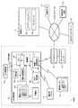
図1に、本発明の実施の形態1のLED照明制御システムの構成図を示す。
(Embodiment 1)
In FIG. 1, the block diagram of the LED illumination control system of Embodiment 1 of this invention is shown.
本実施の形態1のLED照明管10は、蛍光管に代替可能な形状をしている。すなわちLED照明管10は、蛍光管と同様に両端に電極端子を有し、既存の蛍光灯器具に装着して使用できるものである。
The
そして、宅内には、LED照明管10の他に、LED照明管10のLED26を調光するための調光用リモコン13、LED照明管10との間で無線通信を行うアクセスポイント15、アクセスポイント15をインターネット12に接続するためのブロードバンドルーター14が設置されている。
And in the house, in addition to the
また、宅外において、インターネット12には、LED照明管10のLED26の調光を制御するための制御サーバ11、VPNセッションサーバ27、およびLED照明管10の利用者の端末16が接続される。
Further, outside the house, connected to the Internet 12 are a
なお、利用者用端末16は、パソコン、PDA、携帯電話などであり、宅内に設置してインターネット12に接続してもよいし、図1に示すように宅外からインターネット12に接続するようにしてもよい。
The
本実施の形態1のLED照明管10は、その内部に、制御部20、無線送受信部21、ログ保存部22、充電池23、環境センサー24、監視センサー25、およびLED26が配置されたLED基板が設けられている。
The
無線送受信部21は、無線送受信回路を含み、調光用リモコン13およびアクセスポイント15との間でZigBee(登録商標)による無線通信を行う。
The wireless transmission /
ログ保存部22は、EEPROMであり、LED照明管10の24時間分のログを保存している。制御部20が、ログとして、LED照明管10の所定時間毎の、消費電流、消費電力、LED26の調光状態、環境センサー24の検知情報、監視センサー25の感知情報などをログ保存部22に記録する。
The
充電池23は、リチウムポリマー等の内蔵バッテリーであり、夜間電力等により蓄電される。そして、LED照明管10への商用電源からの通電が停止したような場合に、充電池23からの電力がLED26に供給されて非常時の点灯に利用される。充電池23による非常時の点灯は、例えば通常時の50%に減光して点灯させる。
The
環境センサー24は、LED照明管10近傍の、温度、湿度、照度などを検知するセンサーである。これらのセンサーは、当初一部のセンサーのみが設けられていて、順次他のセンサーが追加設置されてもよい。
The
監視センサー25は、人感センサー、振動センサー、カメラなどであり、人体の検知や異常な状況を監視するセンサーである。これらのセンサーは、当初設置されていなくてもよく、その後に順次センサーが追加設置されてもよい。また、監視センサー25として、赤外線センサー、煙センサーなどを設置してもよい。なお、監視センサー25が、本発明の防犯センサーの一例にあたる。
The
制御部20は、無線送受信部21で受信した調光用リモコン13からの調光指示情報にしたがってLED26の調光を制御し、また無線送受信部21およびインターネット12を介して、制御サーバ11との間で各種情報の送受信を行う。
The
制御部20は、制御サーバ11から受信する調光制御情報にしたがってLED26の調光を制御するとともに、ログ保存部22に保存している情報、環境センサー24および監視センサー25から取得した検知情報を制御サーバ11へ送信する。
The
なお、制御部20が、本発明のLED制御部の一例にあたる。
The
調光用リモコン13は、LED照明管10に対して、LED26の点灯、消灯および調光を指示する情報をZigBeeプロトコルにより無線で送信し、LED26をローカルに制御する。なお、調光用リモコン13が、本発明の無線リモコンの一例にあたる。
The dimming
アクセスポイント15は、ZigBeeプロトコルによりLED照明管10の無線送受信部21との間で無線通信を行い、ブロードバンドルーター14を介することにより、LED照明管10の制御部20からインターネット12へのアクセスを可能としている。
The
なお、ブロードバンドルーター14とアクセスポイント15を合わせた構成が、本発明のインターネット接続モデムの一例にあたる。
The configuration combining the
図1では、1つのLED照明管10しか記載していないが、アクセスポイント15には、複数のLED照明管10がZigBeeプロトコルによって接続される。ブロードバンドルーター14は、VPN機能およびルータ機能を備えており、インターネット12を介して接続される制御サーバ11から、宅内に設置されている複数のLED照明管10のそれぞれと、個別に通信が可能となっている。
Although only one
制御サーバ11は、アプリケーションサーバ28およびデータベース29を備えている。
The
VPNセッションサーバ27は、ZigBeeアクセスポイントをVPN化し、制御サーバによる、インターネット12を介して接続される複数のLED照明管10の、個別の制御を可能にしている。
The
アプリケーションサーバ28には、LED照明管10の調光を制御するための照明管理ソフトウェアを備えており、インターネット12を介してLED照明管10の調光を制御する。照明管理ソフトウェアは、利用者によって利用者用端末16から入力された情報、制御サーバ11自身から入力したLED照明管10に関する情報、LED照明管10から取得しデータベース29に蓄積している情報、および気象庁HP17などから取得するインターネット12から得られる情報に基づいて、LED照明管10ごとに調光を制御する。
The
データベース29には、利用者に関する顧客情報、LED照明管10からインターネット12を介して取得したLED照明管10ごとの履歴情報などが蓄積されている。
The
利用者用端末16は、インターネット12を介して制御サーバ11にアクセス可能であり、データベース29に蓄積されているLED照明管10の履歴情報などを参照できるとともに、制御サーバ11に対してLED照明管10に対する調光指示を送信することもできる。
The
次に、図1〜図3を用いて、本実施の形態1のLED照明制御システムの動作について説明する。 Next, operation | movement of the LED illumination control system of this Embodiment 1 is demonstrated using FIGS. 1-3.
図2は、本実施の形態1のLED照明制御システムの各装置間の情報の流れを示している。図3(a)〜(f)は、それぞれ、利用者用端末16における入力画面例および表示画面例を示している。
FIG. 2 shows a flow of information between the devices of the LED lighting control system according to the first embodiment. 3A to 3F show an example of an input screen and an example of a display screen on the
まず、LED照明管10を使用する利用者が、利用者用端末16から、LED照明管10の設置場所に関する情報を入力する。LED照明管10の設置場所に関する情報とは、設置されている場所の住所、建物の高さ、何階に設置されているか、部屋の広さ、窓の有無、窓から設置されている位置までの距離、などの情報である。利用者は、アプリケーションサーバ28によってインターネット12上に提供されているページに利用者用端末16からログインし、これらの利用者情報36を入力する。例えば、図3(a)は利用者のログイン画面を示している。利用者がログイン情報を入力すると図3(b)のような画面が表示され、この画面で「基本情報」を選択すると、図3(c)のような画面が表示され、利用者情報36を入力できるようになる。
First, a user who uses the
また、制御サーバ11自身からも、LED照明管10に関する情報を入力する。例えば、利用者用端末16から利用者が入力した住所の情報から、LED照明管10が設置されている場所の経度および緯度情報を求めて入力する。経度および緯度情報と、日付時間情報、LED照明管10が設置されている階数、窓の位置などの情報から、時間毎の日射角度を求めることができる。経度および緯度情報は、インターネット上の情報を利用することにより、住所から容易に求めることができる。
Moreover, the information regarding the
制御サーバ11は、LED照明管10毎に、個別に各種設定情報30を設定する。各種設定情報30とは、例えば日付や時間情報などである。
The
また、制御サーバ11は、利用者用端末16および制御サーバ11自身に入力された情報と、気象庁HP17から得られる天候に関する情報に基づいて、LED照明管10毎に調光制御情報31を作成し、LED照明管10に送信してLED26の調光を制御する。気象庁HP17から得られる天候に関する情報とは、LED照明管10が設置されている場所における情報であり、例えば、その場所の天気情報、降水量、気温、湿度、風向き、風速などの情報である。
Moreover, the
これらの天候に関する情報は、例えば、気象庁HP17から取得できるHTML文書の中から、対象とするLED照明管10が設置されている地域における天候に関する情報データを抽出するプログラムを作成して、アプリケーションサーバ28が有する照明管理ソフトウェアに組み込んでおき、自動的に取得できるようにしてもよい。このようにすることにより、人間が介在することなく、制御サーバ11によって全自動でLED照明管10の調光を制御することができる。
For example, the
また、制御サーバ11によって自動的にこれらの天候に関する情報を取得するのではなく、制御サーバ11の管理者が、気象庁HP17を見て、対象とするLED照明管10が設置されている地域における天候に関する情報を確認し、その確認した情報を制御サーバ11に入力するようにしてもよい。
In addition, the
また、制御サーバ11は、LED照明管10に対して、定期的に状態確認32を行う。例えば、30分おきに、LED照明管10の環境センサー24で検知された情報を取得する。
In addition, the
LED照明管10の制御部20は、制御サーバ11から受信した調光制御情報31にしたがってLED26の調光を制御するが、そのLED照明管10が設置されている場所の使用者が、LED26が明るすぎるまたは暗すぎると感じた場合には、その使用者は調光用リモコン13を利用してそのLED16の明るさをローカルに調整する。
The
制御部20は、無線送受信部21を介して、調光用リモコン13からの調光指示情報33を受信した場合には、その内容にしたがってLED26の発光を調光するとともに、その調光された状態を示す調光状態情報34を制御サーバ11に送信する。
When the
制御サーバ11は、定期的状態確認32によってLED照明管10から状態情報を取得した場合、および調光状態情報34を取得した場合には、それらの情報を履歴情報としてデータベース29に記録する。
When the
その後、制御サーバ11は、利用者用端末16および制御サーバ11自身に入力された情報と、気象庁HP17から得られる天候に関する情報とともに、データベース29に記録した履歴情報にも基づいてLED照明管10毎の調光制御情報31を作成し、LED照明管10に送信してLED26の調光を制御する。つまり、利用者によってローカルの調光制御が行われたという状況を学習して、その結果を反映した制御が行われることになる。
After that, the
このように制御することにより、LED照明管10が設置されている場所の使用者の要望に沿って調光を制御することができる。例えば、その場所に居る使用者が、最初に設定された調光制御内容では暗すぎると感じた場合には、調光用リモコン13でLED16が明るくなるように調整され、その調整内容が履歴情報としてデータベース29に記録される。そして、その後は、データベース29に記録されたその履歴情報にも基づいて調光が制御されるので、最初に設定された調光制御内容よりも明るくなるように制御されることになる。すなわち、その場所に居る使用者の要望に沿った調光制御がされることになる。
By controlling in this way, dimming can be controlled according to the user's request at the place where the
また、利用者用端末16からも、LED26の調光制御をローカルに行うことができる。アプリケーションサーバ28によってインターネット12上に提供されているページに利用者用端末16からログインし、図3(b)に示す画面で「調光設定」を選択すると、図3(f)のような画面が表示される。利用者が、この画面で調光設定を行うと、その設定に応じた調光指示情報37が制御サーバ11に送信される。
Also, the dimming control of the
制御サーバ11は、利用者用端末16から調光指示情報37を受信すると、その指示内容に応じた調光制御情報31を作成し、指示されたLED照明管10に送信する。LED照明管10の制御部20は、その調光制御情報31にしたがってLED26の発光を調光することにより、利用者が利用者用端末16に設定したローカルの設定にしたがった調光制御が実現される。
When the
また、制御サーバ11は、利用者用端末16から調光指示情報37を受信したときには、その指示内容にしたがった調光制御情報31の内容を履歴情報としてデータベース29に記録する。
Further, when receiving the dimming instruction information 37 from the
したがって、その後、利用者用端末16から入力された調光指示情報37の内容も反映して調光の制御が行われるようになる。つまり、利用者からローカルの調光制御が行われたという状況を学習して、その結果を反映した制御が行われる。
Therefore, the dimming control is performed after reflecting the contents of the dimming instruction information 37 input from the
また、利用者は、利用者用端末16から、データベース29に蓄積されている履歴情報や管理情報を参照することもできる。アプリケーションサーバ28によってインターネット12上に提供されているページに利用者用端末16からログインし、図3(b)に示す画面で「エコモニター」を選択すると、図3(d)のような画面が表示される。さらに図3(d)において、所望のグラフを選択すると、図3(e)のように選択したグラフが拡大表示される。
The user can also refer to the history information and management information stored in the
これにより、利用者は、離れた場所から複数のLED照明管10についての個別の消費電力や、その時間的な推移などを把握することができる。これにより、利用者は、LED照明管10のメンテナンス管理や寿命管理を行うことができる。
Thereby, the user can grasp | ascertain the individual power consumption about the some
また、LED照明管10の制御部20は、監視センサー25が人体や異常を検知した場合には、即座にその監視センサー情報35を制御サーバ11に通知する。
Further, when the
制御サーバ11は、監視センサー情報35が、例えば人の入室を示す情報の場合には、それまでよりもLED26を明るくさせる調光制御情報31を作成して、LED照明管10に送信し、LED26が明るくなるよう制御させる。
When the monitoring sensor information 35 is, for example, information indicating that a person has entered the room, the
また、制御サーバ11受信した監視センサー情報35が、振動センサーによって地震を検知したような場合や、煙センサーによって火災を検知したような場合、また人感センサ0やカメラによって不審者の侵入を検知した場合には、インターネット12を介して利用者に通知するようにしたり、警報装置を作動させるようにしてもよい。
In addition, when the monitoring sensor information 35 received by the
本実施の形態1のLED照明制御システムは、このような動作とすることにより、防犯セキュリティ監視システムとしても利用できる。 The LED lighting control system according to the first embodiment can be used as a security security monitoring system by performing such an operation.
また、制御サーバ11が、複数のLED照明管10の調光を制御する場合において、あるLED照明管10の調光制御内容を他のLED照明管10に反映させるような制御をしてもよい。
In addition, when the
図4は、本実施の形態1のLED照明制御システムの接続構成例を示している。制御サーバ11はインターネット12を介して、複数のLED照明管10を個別に制御できるので、図4のように離れた複数の場所に設置されたLED照明管10を1台の制御サーバ11で制御することができる。
FIG. 4 shows a connection configuration example of the LED illumination control system according to the first embodiment. Since the
例えば、図4に示す、A工場、B工場、C工場が比較的近い場所にある場合に、A工場とB工場の窓の近くに設置されているLED照明管10の所定割合(例えば、50%)以上において所定の短い時間内にローカルで明るくなるよう調光された場合、天候によって外が急に暗くなったと判断して、A工場およびB工場の窓の近くに設置されている他のLED照明管10も明るくなるように制御する調光制御情報31を作成、送信して調光させるように制御してもよい。また、C工場も近くの場所にあるので、C工場の窓の近くに設置されているLED照明管10に対しても明るくなるように制御する調光制御情報31を作成、送信して明るく調光させるように制御してもよい。
For example, when A factory, B factory, and C factory shown in FIG. 4 are relatively close to each other, a predetermined ratio (for example, 50) of
次に、図5に、本実施の形態1の他の構成のLED照明制御システムの構成図を示す。図1と同じ構成部分には、同じ符号を用いている。 Next, in FIG. 5, the block diagram of the LED illumination control system of the other structure of this Embodiment 1 is shown. The same reference numerals are used for the same components as in FIG.
ここでは、図1の構成と異なる部分について説明する。 Here, a different part from the structure of FIG. 1 is demonstrated.
図1に示すLED照明管10が、その内部に監視センサー25を備えていたのに対し、図5に示すLED照明制御システムでは、監視センサー43をLED照明管18の外部の別の場所に設置している点が異なる。
The
また、図5に示すLED照明管18は、内部に可視光通信部41および受光部42を備えている点が、図1に示したLED照明管10と異なる。なお、可視光通信部41が、本発明の可視光通信モジュールの一例にあたる。
Further, the
なお、図5に示すLED照明管19は、LED照明管18と同じ構成のものである。
The
監視センサー43は、監視センサー25と同様に、人体の検知や異常な状況を監視するセンサーである。
Similar to the
監視センサー43は、ZigBeeプロトコルによる無線送信機能を備えており、LED照明管18の無線送受信部21との間で無線通信を行う。
The
監視センサー43は、人体の検知や異常な状況を検知すると、その情報をLED照明管18の無線送受信部21に送信する。LED照明管18の制御部40は、無線送受信部21を介して監視センサー43からの検知情報を受信すると、その情報に対応する図2に示した監視センサー情報35を制御サーバ11に送信する。以降の動作は、図1のLED照明制御システムにおいて監視センサー25が人体の検知や異常な状況を検知した場合と同様である。
When the
可視光通信部41は、制御部40から渡されたデータを、LED26を点滅制御させることによって可視光通信により送信する。また、可視光通信部41は、受光部42で受光した他のLED照明管19からの可視光の点滅情報から取得した可視光通信による受信データを制御部40に渡す。
The visible
このようにして、LED照明管18およびLED照明管19の制御部40同士の間で、可視光通信によるデータの送受信が行われる。
In this manner, data is transmitted and received by visible light communication between the
なお、本実施の形態1の制御サーバ11は、1本ずつのLED照明管10を個別に制御するようにしてもよいし、複数本のLED照明管10を一単位として、その単位ごとに個別に制御するようにしてもよい。複数本のLED照明管10の一単位として、例えば、窓に近い位置に設置されている複数本の組としたり、狭い部屋の場合にはその部屋に含まれる全てのLED照明管10を一つの単位としてもよい。
The
また、人は、点灯直後は暗さを感じ易いのに対して点灯して所定時間した後に少し暗くなっても暗くなったことを感じ難いという傾向があるので、アプリケーションサーバ28の照明管理ソフトウェアによる調光制御として、点灯時は少し明るめに設定しておき、その後、所定期間後に少し暗くなるように徐々に減光していくような制御としてもよい。このように制御することにより、使用者にとって不快感なく、節電することができる。 In addition, since people tend to feel dark immediately after lighting, they tend to be less likely to feel dark even if it is dark for a while after being turned on. As the dimming control, it may be set so that it is set a little brighter at the time of lighting and then gradually dimmed so that it becomes a little dark after a predetermined period. By controlling in this way, it is possible to save power without discomfort for the user.
また、本実施の形態では、各機器間の無線通信にZigBeeプロトコルを用いることとしたが、他の無線方式を利用するものであってもよい。例えば、ブルートゥース(登録商標)、Wi−fi(登録商標)、Wi−max(登録商標)、GSM、RFなど、どのような無線方式であってもよい。 In the present embodiment, the ZigBee protocol is used for wireless communication between devices, but other wireless systems may be used. For example, any wireless system such as Bluetooth (registered trademark), Wi-fi (registered trademark), Wi-max (registered trademark), GSM, and RF may be used.
以上に説明したように、本発明のLED照明制御システムを用いると、複数のLED照明管10を、個別に、それぞれの設置場所の環境や使用者の要望に応じて制御することができる。
As described above, when the LED illumination control system of the present invention is used, the plurality of
本発明のLED照明制御システムは、複数の場所にある工場や事務所などのLED照明の制御および管理を、集中して行うことを実現できる。したがって、制御サーバ11によって、複数の会社の工場や事務所などのLED照明の制御および管理を個別に行うことも実現できる。
The LED lighting control system of the present invention can realize centralized control and management of LED lighting in factories and offices in a plurality of places. Therefore, the
本発明に係るLED照明制御システムは、周りの環境や使用者の使用状況に応じて柔軟な調光制御が行える効果を有し、LED照明の調光を制御するLED照明制御システム等として有用である。 The LED lighting control system according to the present invention has an effect of performing flexible dimming control according to the surrounding environment and the usage status of the user, and is useful as an LED lighting control system for controlling the dimming of the LED lighting. is there.
10、18、19 LED照明管
11 制御サーバ
12 インターネット
13 調光用リモコン
14 ブロードバンドルーター
15 アクセスポイント
16 利用者用端末
17 気象庁HP
20 制御部
21 無線送受信部
22 ログ保存部
23 充電池
24 環境センサー
25 監視センサー
26 LED
27 VPNセッションサーバ
28 アプリケーションサーバ
29 データベース
30 各種設定情報
31 調光制御情報
32 定期的状態確認
33 調光指示情報
34 調光状態情報
35 監視センサー情報
36 利用者情報
37 調光指示情報
38 履歴・管理情報
40 制御部
41 可視光通信部
43 監視センサー
10, 18, 19
20
27
Claims (8)
前記LED照明管に対して、前記LEDの点灯、消灯および調光の指示を無線で送信する無線リモコンと、
無線により前記LED照明管とデータの送受信を行い、前記無線により送受信されるデータをインターネットに中継するインターネット接続モデムと、
前記インターネットを介して前記インターネット接続モデムに接続され、少なくとも前記LEDの調光を制御する制御サーバと、
前記インターネットを介して、前記制御サーバに接続される利用者用端末とを備えたLED照明制御システムであって、
前記制御サーバは、前記利用者用端末および前記制御サーバ自身に入力された入力データ、前記インターネットから取得する少なくとも天候及び日射角度に関する情報、および前記LED照明管に対して前記無線リモコンから送信されてきた指示情報に基づいて前記LEDの調光を制御し、
前記日射角度は、少なくとも、前記LED照明管の設置場所情報と、現在の日付時間情報とから演算され、
さらに、前記LED照明管は、複数あり、
前記制御サーバは、所定の範囲に属する複数の前記LED照明管を、その単位ごとに個別に調光を制御し、所定数以上の前記LED照明管単位に対して前記無線リモコンによる調光が指示された場合には、その指示内容に基づいて、前記所定の範囲に属する、前記調光が指示された以外の前記LED照明管単位の全部または所定割合以上の調光を制御する、LED照明制御システム。 An LED lighting tube having an LED substrate on which LEDs are arranged, a wireless transmission / reception circuit, and an LED control unit that controls lighting, extinction, and dimming of the LEDs;
A wireless remote controller for wirelessly transmitting instructions for turning on, turning off, and dimming the LED to the LED lighting tube;
An internet connection modem that wirelessly transmits and receives data to and from the LED lighting tube and relays the wirelessly transmitted and received data to the Internet;
A control server connected to the Internet connection modem via the Internet and controlling dimming of at least the LED;
An LED lighting control system comprising a user terminal connected to the control server via the Internet,
The control server is transmitted from the wireless remote controller to the user terminal and input data input to the control server itself, information on at least weather and solar radiation angles acquired from the Internet, and the LED lighting tube. Control dimming of the LED based on the indicated information,
The solar radiation angle is calculated from at least the installation location information of the LED lighting tube and the current date time information,
Furthermore, there are a plurality of the LED lighting tubes,
The control server individually controls dimming for each of the plurality of LED lighting tubes belonging to a predetermined range, and dimming by the wireless remote controller is instructed to a predetermined number or more of the LED lighting tubes. If it is, the LED lighting control that controls the dimming of all the LED lighting tube units other than the dimming instruction that belongs to the predetermined range or the predetermined ratio or more, based on the content of the instruction. system.
前記LED照明管へ供給されている電力が停止した場合には、前記LEDは、前記充電池から供給される電力によって発光する、請求項1〜4のいずれかに記載のLED照明制御システム。 The LED lighting tube has a rechargeable battery,
The LED illumination control system according to any one of claims 1 to 4, wherein when the power supplied to the LED lighting tube is stopped, the LED emits light by the power supplied from the rechargeable battery.
前記LED制御部は、前記カメラで撮影した映像データおよび前記防犯センサーで検知した検知データの少なくともいずれかを前記インターネットを介して前記制御サーバに通知する、請求項1〜5のいずれかに記載のLED照明制御システム。 The LED lighting tube has at least one of a camera and a security sensor,
The said LED control part notifies at least any one of the video data image | photographed with the said camera, and the detection data detected with the said security sensor to the said control server via the said internet. LED lighting control system.
前記利用者端末は、前記インターネットを介して前記制御サーバで管理されている前記履歴を参照できる、請求項1〜6のいずれかに記載のLED照明制御システム。 The control server manages a history for each LED lighting tube,
The LED lighting control system according to claim 1, wherein the user terminal can refer to the history managed by the control server via the Internet.
Priority Applications (1)
| Application Number | Priority Date | Filing Date | Title |
|---|---|---|---|
| JP2009086124A JP4605486B2 (en) | 2009-03-31 | 2009-03-31 | LED lighting control system |
Applications Claiming Priority (1)
| Application Number | Priority Date | Filing Date | Title |
|---|---|---|---|
| JP2009086124A JP4605486B2 (en) | 2009-03-31 | 2009-03-31 | LED lighting control system |
Publications (2)
| Publication Number | Publication Date |
|---|---|
| JP2010238572A JP2010238572A (en) | 2010-10-21 |
| JP4605486B2 true JP4605486B2 (en) | 2011-01-05 |
Family
ID=43092719
Family Applications (1)
| Application Number | Title | Priority Date | Filing Date |
|---|---|---|---|
| JP2009086124A Expired - Fee Related JP4605486B2 (en) | 2009-03-31 | 2009-03-31 | LED lighting control system |
Country Status (1)
| Country | Link |
|---|---|
| JP (1) | JP4605486B2 (en) |
Families Citing this family (19)
| Publication number | Priority date | Publication date | Assignee | Title |
|---|---|---|---|---|
| JP5495060B2 (en) * | 2010-08-05 | 2014-05-21 | 清水建設株式会社 | Environmental control device |
| JP6143762B2 (en) * | 2011-10-25 | 2017-06-07 | フィリップス ライティング ホールディング ビー ヴィ | Method and apparatus for controlling lighting in an interior space |
| US9084313B2 (en) * | 2012-02-15 | 2015-07-14 | Anycomm Corporation | Smart bulb system |
| TWI487931B (en) * | 2012-10-01 | 2015-06-11 | Internat Mobile Iot Corp | Earth positioning system |
| JP6098273B2 (en) * | 2013-03-25 | 2017-03-22 | 東芝ライテック株式会社 | Lighting control apparatus and lighting control system |
| WO2014203537A1 (en) * | 2013-06-20 | 2014-12-24 | 株式会社遠藤照明 | Illumination control device, and illumination system |
| JP6370131B2 (en) * | 2013-09-10 | 2018-08-08 | パナソニック インテレクチュアル プロパティ コーポレーション オブ アメリカPanasonic Intellectual Property Corporation of America | Communication terminal control method, program, and illumination control system |
| TW201519697A (en) * | 2013-11-15 | 2015-05-16 | Gunitech Corp | Light source control system and method for controlling the same |
| KR101694581B1 (en) * | 2014-01-23 | 2017-01-09 | 한국광기술원 | Smart lighting device for bathroom and control system for using the same |
| KR101772743B1 (en) * | 2015-01-14 | 2017-08-29 | 엘지이노텍 주식회사 | Mobile terminal, lighting apparatus and lighting system |
| CN104602414B (en) * | 2015-01-22 | 2017-05-24 | 生迪光电科技股份有限公司 | Intelligent lighting device, control terminal and lighting system |
| JP6651755B2 (en) * | 2015-09-14 | 2020-02-19 | 東芝ライテック株式会社 | Lighting system |
| JP6771147B2 (en) | 2016-06-22 | 2020-10-21 | パナソニックIpマネジメント株式会社 | Bath light system and mobile terminal |
| JP7007702B2 (en) * | 2017-05-29 | 2022-01-25 | ヒカリレンタ株式会社 | Light emitting device and light emitting life data management system |
| CN109116978B (en) * | 2018-06-06 | 2021-03-23 | 北京物灵智能科技有限公司 | Light emitting device, interaction method thereof, electronic device and storage medium |
| JP7210973B2 (en) * | 2018-09-28 | 2023-01-24 | 東芝ライテック株式会社 | Information processing system |
| JP7452115B2 (en) * | 2020-03-11 | 2024-03-19 | 三菱電機株式会社 | Lighting control systems and controllers |
| CN111511084A (en) * | 2020-04-20 | 2020-08-07 | 北京智米科技有限公司 | Intelligent lamp control method and system and lamp |
| JP7489050B2 (en) * | 2021-01-20 | 2024-05-23 | ボクシーズ株式会社 | Light |
Family Cites Families (11)
| Publication number | Priority date | Publication date | Assignee | Title |
|---|---|---|---|---|
| JPH11238579A (en) * | 1998-02-24 | 1999-08-31 | Matsushita Electric Works Ltd | Lighting equipment |
| JP4186450B2 (en) * | 2001-10-16 | 2008-11-26 | 株式会社日立製作所 | Air conditioning equipment operation system and air conditioning equipment design support system |
| JP2003243188A (en) * | 2002-02-15 | 2003-08-29 | Matsushita Electric Works Ltd | Lighting system |
| JP2004030933A (en) * | 2002-06-21 | 2004-01-29 | Hitachi Ltd | Lighting control device |
| JP2005216534A (en) * | 2004-01-27 | 2005-08-11 | Matsushita Electric Works Ltd | Lighting control system, lighting control software distribution server, and lighting control communication terminal |
| JP4784259B2 (en) * | 2005-10-26 | 2011-10-05 | パナソニック電工株式会社 | Solar radiation shielding control device |
| JP2008159457A (en) * | 2006-12-25 | 2008-07-10 | Momo Alliance Co Ltd | Lighting device |
| JP4976149B2 (en) * | 2007-01-26 | 2012-07-18 | パナソニック株式会社 | Disaster prevention lighting system |
| JP2008204393A (en) * | 2007-02-22 | 2008-09-04 | Matsushita Electric Works Ltd | Lighting system |
| JP2008276354A (en) * | 2007-04-26 | 2008-11-13 | Nippon Telegr & Teleph Corp <Ntt> | Crime prevention method in home network system, crime prevention method in office network system, and home network system |
| JP2009048988A (en) * | 2007-07-20 | 2009-03-05 | Toshiba Lighting & Technology Corp | Lighting control system |
-
2009
- 2009-03-31 JP JP2009086124A patent/JP4605486B2/en not_active Expired - Fee Related
Also Published As
| Publication number | Publication date |
|---|---|
| JP2010238572A (en) | 2010-10-21 |
Similar Documents
| Publication | Publication Date | Title |
|---|---|---|
| JP4605486B2 (en) | LED lighting control system | |
| US7480534B2 (en) | Computer assisted lighting control system | |
| US20120146518A1 (en) | Predicative lighting control system | |
| US10412811B1 (en) | Electronic devices for controlling lights | |
| CN204790346U (en) | Intelligence household security system based on thing networking | |
| JP6290373B2 (en) | Daylight daylighting system to prevent unauthorized changes | |
| CN204705882U (en) | A kind of intelligent domestic system | |
| EP1699028B1 (en) | Wireless alarm system with remote alarm receipt | |
| US20100148672A1 (en) | Energy Efficient Lighting System and Method | |
| US20160321891A1 (en) | Method, apparatus, and system for controlling smart home environment using led lighting device | |
| US20120310415A1 (en) | Control panel for a control system and a control system | |
| US9332616B1 (en) | Path light feedback compensation | |
| US11039520B1 (en) | Electronic devices for controlling lights | |
| TW201125438A (en) | Light guiding system and a method for controlling the same | |
| KR20120114510A (en) | Intelligently safety lighting system | |
| KR102195882B1 (en) | APPARATUS FOR IoT BASED SMART LIGHTING CONTROL AND THE CONTROL METHOD THEREOF | |
| KR102393139B1 (en) | System for managing building energy based on indoor location and method thereof | |
| JP7457961B2 (en) | Equipment information transmission device, remote information collection system, and status-related information transmission method | |
| JP4631194B2 (en) | Evacuation guidance system | |
| KR102095285B1 (en) | Power saving control system using remote control communication | |
| KR101186223B1 (en) | Electric power control system using a mobile communication device | |
| KR102500379B1 (en) | Event-based Smart Lighting Common Platform System | |
| KR102618697B1 (en) | The control appartus for landscape lighting contained to segment display | |
| CN205071380U (en) | A sensor light system with intrusion alarm function | |
| JP5988198B2 (en) | Lighting device |
Legal Events
| Date | Code | Title | Description |
|---|---|---|---|
| TRDD | Decision of grant or rejection written | ||
| A01 | Written decision to grant a patent or to grant a registration (utility model) |
Free format text: JAPANESE INTERMEDIATE CODE: A01 Effective date: 20100914 |
|
| A01 | Written decision to grant a patent or to grant a registration (utility model) |
Free format text: JAPANESE INTERMEDIATE CODE: A01 |
|
| A61 | First payment of annual fees (during grant procedure) |
Free format text: JAPANESE INTERMEDIATE CODE: A61 Effective date: 20100922 |
|
| R150 | Certificate of patent or registration of utility model |
Ref document number: 4605486 Country of ref document: JP Free format text: JAPANESE INTERMEDIATE CODE: R150 Free format text: JAPANESE INTERMEDIATE CODE: R150 |
|
| FPAY | Renewal fee payment (event date is renewal date of database) |
Free format text: PAYMENT UNTIL: 20131015 Year of fee payment: 3 |
|
| R250 | Receipt of annual fees |
Free format text: JAPANESE INTERMEDIATE CODE: R250 |
|
| S201 | Request for registration of exclusive licence |
Free format text: JAPANESE INTERMEDIATE CODE: R314201 |
|
| R360 | Written notification for declining of transfer of rights |
Free format text: JAPANESE INTERMEDIATE CODE: R360 |
|
| R360 | Written notification for declining of transfer of rights |
Free format text: JAPANESE INTERMEDIATE CODE: R360 |
|
| R371 | Transfer withdrawn |
Free format text: JAPANESE INTERMEDIATE CODE: R371 |
|
| S201 | Request for registration of exclusive licence |
Free format text: JAPANESE INTERMEDIATE CODE: R314201 |
|
| R350 | Written notification of registration of transfer |
Free format text: JAPANESE INTERMEDIATE CODE: R350 |
|
| R250 | Receipt of annual fees |
Free format text: JAPANESE INTERMEDIATE CODE: R250 |
|
| R250 | Receipt of annual fees |
Free format text: JAPANESE INTERMEDIATE CODE: R250 |
|
| LAPS | Cancellation because of no payment of annual fees |