JP4600767B2 - LED lamp - Google Patents
LED lamp Download PDFInfo
- Publication number
- JP4600767B2 JP4600767B2 JP2005319968A JP2005319968A JP4600767B2 JP 4600767 B2 JP4600767 B2 JP 4600767B2 JP 2005319968 A JP2005319968 A JP 2005319968A JP 2005319968 A JP2005319968 A JP 2005319968A JP 4600767 B2 JP4600767 B2 JP 4600767B2
- Authority
- JP
- Japan
- Prior art keywords
- led lamp
- heat
- turbulent flow
- radiating fin
- led
- Prior art date
- Legal status (The legal status is an assumption and is not a legal conclusion. Google has not performed a legal analysis and makes no representation as to the accuracy of the status listed.)
- Expired - Fee Related
Links
- 238000011144 upstream manufacturing Methods 0.000 claims description 8
- 239000000463 material Substances 0.000 claims description 6
- 230000005855 radiation Effects 0.000 description 16
- 230000017525 heat dissipation Effects 0.000 description 13
- 230000000694 effects Effects 0.000 description 9
- 239000011347 resin Substances 0.000 description 5
- 229920005989 resin Polymers 0.000 description 5
- 238000001816 cooling Methods 0.000 description 4
- 230000007423 decrease Effects 0.000 description 3
- 238000005259 measurement Methods 0.000 description 3
- 229910052751 metal Inorganic materials 0.000 description 3
- 239000002184 metal Substances 0.000 description 3
- 229910052782 aluminium Inorganic materials 0.000 description 2
- XAGFODPZIPBFFR-UHFFFAOYSA-N aluminium Chemical compound [Al] XAGFODPZIPBFFR-UHFFFAOYSA-N 0.000 description 2
- 239000000428 dust Substances 0.000 description 2
- 238000002474 experimental method Methods 0.000 description 2
- 239000004065 semiconductor Substances 0.000 description 2
- 239000000758 substrate Substances 0.000 description 2
- 238000010521 absorption reaction Methods 0.000 description 1
- 238000009529 body temperature measurement Methods 0.000 description 1
- 239000004020 conductor Substances 0.000 description 1
- 238000012790 confirmation Methods 0.000 description 1
- 230000006378 damage Effects 0.000 description 1
- 230000003247 decreasing effect Effects 0.000 description 1
- 239000013013 elastic material Substances 0.000 description 1
- 238000005516 engineering process Methods 0.000 description 1
- 230000020169 heat generation Effects 0.000 description 1
- 238000005286 illumination Methods 0.000 description 1
- 239000011810 insulating material Substances 0.000 description 1
- 238000009413 insulation Methods 0.000 description 1
Images


Landscapes
- Arrangement Of Elements, Cooling, Sealing, Or The Like Of Lighting Devices (AREA)
- Non-Portable Lighting Devices Or Systems Thereof (AREA)
Description
本発明は、光源としてLED素子を使用したヘッドランプ等の車両用灯具を含むLEDランプに関する。 The present invention relates to an LED lamp including a vehicular lamp such as a headlamp using an LED element as a light source.
従来、光源としてLED素子を使用したLEDヘッドランプは、例えば図8に示すように構成されている。
即ち、図8において、LEDヘッドランプ1は、前面が開放した樹脂製の筐体2と、この筐体2内に設けられた複数個のLEDランプユニット3と、筐体2の前面を覆うように筐体2に取り付けられた透光性樹脂材料から成る前面レンズ4と、から構成されている。
上記各LEDランプユニット3は、それぞれ少なくとも一つのLED素子を含んでおり、前方に向かって光を出射するように、ランプユニット支持体3aにより筐体2の内側に支持されている。
Conventionally, an LED headlamp using an LED element as a light source is configured, for example, as shown in FIG.
That is, in FIG. 8, the
Each of the
このような構成のLEDヘッドランプ1によれば、各LEDランプユニット3に対して外部から給電することにより、各LEDランプユニット3のLED素子が駆動され、発光する。そして、各LEDランプユニット3から出射した光が、上記前面レンズ4を介して前方に向かって照射される。
According to the
このようなLEDヘッドランプ1においては、個々のLED素子の発光に伴って熱が発生する。
これに対して、LED素子は一般的に温度に対して負の特性を有している。即ち、LED素子は、温度が上昇するに従って発光効率が低減することが知られている。
従って、LEDヘッドランプにおいては、筐体2及び前面レンズ4が熱伝導性の低い樹脂製である場合が多いことから、特に各LED素子の発熱に対する対策が重要である。
In such an
In contrast, LED elements generally have negative characteristics with respect to temperature. That is, it is known that the luminous efficiency of the LED element decreases as the temperature rises.
Therefore, in the LED headlamp, since the
例えば、特許文献1においては、筐体内温度を検出して、この筐体内温度に基づいて、LED素子に供給する駆動電流を制御することにより、温度上昇時には各LED素子の発熱量を抑制するようにした、車両用灯具が開示されている。
For example, in
また、特許文献2には、各LED素子をそれぞれ熱容量の大きな金属製支持部材上に支持して、各LED素子で発生する熱を金属製支持部材に伝導させて、各LED素子の放熱を行なうようにした、車両用前照灯が開示されている。
In
さらに、特許文献3には、各LED素子をヒートパイプの一端付近に支持すると共に、このヒートパイプの他端を筐体外部に配置することにより、各LED素子で発生する熱をヒートパイプを介して筐体外部に放出するようにした、車両用灯具が開示されている。
Further, in
さらにまた、特許文献4には、LED素子を含む面光源を、ケース外に突出する放熱フィンを有するヒートシンクに固着すると共に、前方から放熱フィン付近に空気流を導入するための通気口を設けて、上記面光源の各LED素子で発生する熱をヒートシンクから放熱フィンを介して外部に伝導させて、通気口からの空気流により空冷して、各LED素子の放熱を行なうようにした、LEDランプが開示されている。
Furthermore, in
また、特許文献5には、半導体発光素子が直接に平板上の放熱基板の上面に固定されており、半導体発光素子で発生する熱を放熱基板を介して外部に伝導させて、半導体発光素子の放熱を行なうようにした、灯具が開示されている。
ところで、これらの特許文献1から5による技術においては、いずれも各LED素子で発生する熱を筐体内または筐体外に伝導させることによって、筐体内部全体の温度を低下させるように構成されている。
しかしながら、何れの場合にも、放熱部材等を利用して放熱を行なうようになってはいるが、これら放熱部材等の放熱効率を積極的に高めるような対策はとられておらず、放熱効果に限界がある。
By the way, in each of the technologies according to
However, in any case, heat dissipation is performed using a heat radiating member, etc., but no measures are taken to positively increase the heat radiating efficiency of these heat radiating members, etc. There is a limit.
さらに、筐体内に熱を伝導させて放熱を行なう場合には、筐体内全体の温度が上昇することになるため、LED素子の発光効率が低下してしまい、場合によってはLED素子のジャンクション温度を越えて、温度破壊が発生するおそれもある。
また、筐体外に熱を伝導させて放熱を行なう場合、放熱部材等が筐体を貫通して外部に引き出されることになるため、この引出し部分が雨水や粉塵等に対して曝されることになるので、信頼性が低下してしまうことになる。
Further, when heat is conducted by conducting heat in the housing, the temperature inside the housing rises, so that the luminous efficiency of the LED element decreases, and in some cases the junction temperature of the LED element is reduced. There is also a risk of temperature destruction.
In addition, when heat is conducted by conducting heat outside the housing, the heat radiating member and the like penetrates the housing and is drawn out to the outside, so that this drawn portion is exposed to rainwater, dust, etc. As a result, the reliability is lowered.
本発明は、以上の点から、放熱部材による放熱効果を積極的に高めることにより、放熱効率を向上させるようにして、筐体内の温度上昇を効果的に抑制するようにしたLEDランプを提供することを目的としている。 In view of the above, the present invention provides an LED lamp in which the heat dissipation effect by the heat dissipation member is positively enhanced to improve the heat dissipation efficiency and effectively suppress the temperature rise in the housing. The purpose is that.
上記目的は、本発明によれば、前方が開放した筐体と、この筐体内で前方に向かって光を照射するように配置された少なくとも一つのLED素子を有するLEDランプユニットと、上記筐体の開放した前面を閉じる透光性材料から成る前面レンズと、上記LEDランプユニットに対して熱的に接続され且つ筐体外に突出する放熱フィンを備えた放熱部材と、上記放熱部材の放熱フィンに自動車の走行時の走行風を導くためのダクトと、を含んでいるLEDランプにおいて、上記ダクトの断面積が、上記放熱フィンの空気流に対する断面積に近いように選定されていると共に、上記ダクト内の放熱フィン上流側に、空気流に乱流を付与する乱流板が配置され、上記乱流板が、上記放熱フィンに近接して配置されていると共に、その高さが放熱フィンの高さの半分以下に選定されていることを特徴とする、LEDランプにより、達成される。 According to the present invention, the object is to provide an LED lamp unit having a housing open at the front, at least one LED element arranged to irradiate light forward in the housing, and the housing. A front lens made of a translucent material that closes the opened front surface, a heat dissipating member that is thermally connected to the LED lamp unit and protrudes out of the housing, and a heat dissipating fin of the heat dissipating member. In an LED lamp including a duct for guiding a driving wind during driving of an automobile, a cross-sectional area of the duct is selected so as to be close to a cross-sectional area with respect to an air flow of the radiating fin, and the duct the radiating fins upstream of the inner turbulence plate is arranged to impart turbulence to the air flow, the turbulent flow plate is arranged closer in proximity to the heat radiation fins, the height of the heat radiating off Characterized in that it is selected to less than half the emissions of height, the LED lamp is achieved.
本発明によるLEDランプは、好ましくは、上記乱流板が、上記放熱フィンの根元側に配置されている。 In the LED lamp according to the present invention, preferably, the turbulent plate is disposed on a base side of the heat radiating fin.
本発明によるLEDランプは、好ましくは、上記乱流板が、上記放熱フィンの先端側に配置されている。 In the LED lamp according to the present invention, preferably, the turbulent flow plate is disposed on a front end side of the radiating fin.
本発明によるLEDランプは、好ましくは、上記乱流板が、上記放熱フィンからやや離反して配置されていると共に、その高さが放熱フィンの高さの半分程度に選定されている。 In the LED lamp according to the present invention, preferably, the turbulent plate is disposed slightly apart from the radiating fin, and the height thereof is selected to be about half the height of the radiating fin.
上記構成によれば、LEDランプユニットの各LED素子に対して外部から給電することにより、個々のLED素子が駆動され、LEDランプユニットが発光する。そして、LEDランプユニットから出射した光が、上記前面レンズを介して前方に向かって照射される。 According to the said structure, by supplying electric power from the exterior with respect to each LED element of an LED lamp unit, each LED element is driven and an LED lamp unit light-emits. And the light radiate | emitted from the LED lamp unit is irradiated toward the front through the said front lens.
この場合、各LEDランプユニットのLED素子で発生した熱は、上記放熱部材に伝達され、この放熱部材の放熱フィンが、自動車の走行時に上記ダクト内に導入される空気流によって、強制的に空冷されることになる。
その際、上記ダクトの内面と上記放熱フィンの外縁との間の間隔が狭く設定されていることにより、上記ダクト内に導入される空気流が効率良く上記放熱フィンを空冷することになる。
In this case, the heat generated in the LED elements of each LED lamp unit is transmitted to the heat radiating member, and the heat radiating fins of the heat radiating member are forcibly cooled by the air flow introduced into the duct when the automobile is running. Will be.
At that time, since the distance between the inner surface of the duct and the outer edge of the radiating fin is set narrow, the air flow introduced into the duct efficiently cools the radiating fin.
さらに、上記ダクト内にて上記放熱フィンの上流側にて、好ましくは上記放熱フィンの根元側または先端側に、乱流板が配置されていることにより、ダクト内を放熱フィンに向かって流れる層流としての空気流が上記乱流板にぶつかることによって乱流となる。これにより、放熱フィンに対してより多くの空気流が触れることから、空冷がより一層効果的に行なわれ得ることになる。
これにより、各LED素子の温度上昇が抑制され得ることになるので、各LED素子の発光効率が低下するようなことはなく、高輝度の光が前方に向かって照射され得ることになる。
Furthermore, a layer that flows in the duct toward the radiating fin by disposing a turbulent flow plate on the upstream side of the radiating fin in the duct, preferably on the base side or the tip side of the radiating fin. A turbulent flow is created when the air flow as a flow hits the turbulent plate. Thereby, since more airflows touch a radiation fin, air cooling can be performed still more effectively.
Thereby, since the temperature rise of each LED element can be suppressed, the light emission efficiency of each LED element does not fall, and high-intensity light can be irradiated toward the front.
上記乱流板が、上記放熱フィンに近接して配置されていると共に、その高さが放熱フィンの高さの半分以下に選定されている場合には、上記乱流板により発生した乱流が、近接している上記放熱フィン全体に導かれ、効率良く空冷を行なうことになる。 When the turbulent plate is disposed close to the radiating fin and its height is selected to be less than half the height of the radiating fin, the turbulent flow generated by the turbulent plate is Then, it is guided to the entire heat dissipating fins close to each other, and air cooling is performed efficiently.
上記乱流板が、上記放熱フィンから離反して配置されていると共に、その高さが放熱フィンの高さの半分程度に選定されている場合には、上記乱流板によりダクトの中間高さ付近で発生した乱流が、やや離反している上記放熱フィン全体に導かれ、効率良く空冷を行なうことになる。 When the turbulent plate is disposed away from the radiating fin and its height is selected to be about half the height of the radiating fin, the turbulent plate causes the intermediate height of the duct to be The turbulent flow generated in the vicinity is guided to the entire heat dissipating fins that are separated slightly, and air cooling is performed efficiently.
このようにして、本発明によれば、少なくとも一つのLED素子から成るLEDランプ、例えば自動車用LEDヘッドランプ等の車両用のLEDランプにおいて、各LED素子からLEDランプユニットを介して放熱部材まで熱が移動されると共に、この放熱部材の放熱フィンがダクト内に導入される空気流により強制的に空冷され、さらに上記空気流が上記放熱フィンの上流側に設けられた乱流板により乱流となる。
これにより、上記放熱フィンの周囲にて生じる乱流によって、より多量の空気が上記放熱フィンに接触することになるので吸熱効果が高くなり、上記乱流によって効率的に空冷が行なわれることになる。
従って、上記各LED素子の温度上昇が効率的に抑制され得るので、LED素子の適切な駆動温度が維持でき、LEDランプユニットの個々のLED素子の発光効率の低下が抑制され、より明るい光が照射され得ることになる。
Thus, according to the present invention, in an LED lamp composed of at least one LED element, for example, a vehicle LED lamp such as an automobile LED headlamp, heat is transmitted from each LED element to the heat dissipation member via the LED lamp unit. The radiating fins of the radiating member are forcibly cooled by the air flow introduced into the duct, and the air flow is further turbulent by the turbulent flow plate provided on the upstream side of the radiating fins. Become.
As a result, a larger amount of air comes into contact with the heat radiating fin due to the turbulent flow generated around the heat radiating fin, so that the heat absorption effect is enhanced, and the air cooling is efficiently performed by the turbulent flow. .
Therefore, since the temperature rise of each LED element can be efficiently suppressed, the appropriate driving temperature of the LED element can be maintained, the decrease in the luminous efficiency of the individual LED elements of the LED lamp unit is suppressed, and brighter light is emitted. It can be irradiated.
以下、この発明の好適な実施形態を図1〜7を参照しながら、詳細に説明する。尚、以下に述べる実施形態は、本発明の好適な具体例であるから、技術的に好ましい種々の限定が付されているが、本発明の範囲は、以下の説明において特に本発明を限定する旨の記載がない限り、これらの態様に限られるものではない。[実施例1] Hereinafter, a preferred embodiment of the present invention will be described in detail with reference to FIGS. The embodiments described below are preferable specific examples of the present invention, and thus various technically preferable limitations are given. However, the scope of the present invention particularly limits the present invention in the following description. As long as there is no description of the effect, it is not restricted to these aspects. [Example 1]
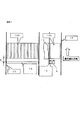
図1は、本発明によるLEDランプの一実施形態の構成を示している。
図1において、LEDランプ10は、自動車用のLEDヘッドランプであって、前面が開放した樹脂製の筐体11と、この筐体11内に設けられた複数個のLEDランプユニット12と、筐体11の前面を覆うように筐体11に取り付けられた透光性樹脂材料から成る前面レンズ13と、放熱部材14と、ダクト15と、乱流板16と、から構成されている。
FIG. 1 shows the configuration of an embodiment of an LED lamp according to the present invention.
In FIG. 1, an
各LEDランプユニット12は、それぞれ少なくとも一つのLED素子(図示せず)を含んでおり、前方に向かって光を出射するように、ランプユニット支持体12aにより後述する放熱部材14に対して支持されている。
ここで、上記ランプユニット支持体12aは、LEDランプユニット12の放熱を促進するために、熱伝導率の高い材料、例えばアルミニウム等の金属から形成されている。
Each
Here, the lamp unit support 12a is formed of a material having a high thermal conductivity, for example, a metal such as aluminum, in order to promote heat dissipation of the
以上の構成は、図8に示した従来のLEDランプ1と同様の構成であるが、本発明実施形態によるLEDランプ10においては、さらに放熱部材14,ダクト15及び乱流板16を含んでいる。
ここで、上記放熱部材14は、上述したランプユニット支持体12aと同様に、高熱伝導性材料、例えばアルミニウム等から板状に構成されており、上記筐体11の開放した後面を閉塞するように、弾性材14aを介して筐体11に対して取り付けられている。
The above configuration is the same as the
Here, similarly to the lamp unit support 12a described above, the
そして、上記放熱部材14の筐体11内に露出する前面に対して、上述したLEDランプユニット12が、ランプユニット支持体12aを介して、支持されていると共に、熱的に接続されている。
And the
さらに、上記放熱部材14は、図1にて後方に突出する放熱フィン14bを備えており、この放熱フィン14bが実際の放熱部材(ヒートシンク)として機能するようになっている。
Further, the
また、上記ダクト15は、エンジン熱からの断熱,雨水や粉塵等に対する暴露軽減,走行風の効果的利用,停止時の煙突効果による放熱のために、上記筐体11の下面及び後面に沿って空気流の通路を画成するように、備えられており、好ましくは断熱材料から構成されている。
その際、上記ダクト15は、その入口15aができるだけ前方に延びるように、また出口15bができるだけ放熱部材14から遠くなるように、配置されている。
これにより、自動車の走行時に、上記ダクト15の入口15aから空気流が流入し、ダクト15内に沿って出口15bまで流れるようになっている。
The
At that time, the
As a result, when the vehicle is running, an air flow flows from the inlet 15a of the
ここで、上記放熱部材14は、このダクト15内に配置されるようになっており、その際、ダクト15は、その断面の高さが、放熱部材14に対して効率良く空気流を導くように、放熱部材14の放熱フィン14bの断面の高さに対して、0から20mmだけ大きく選定されるようになっている。
Here, the
また、上記乱流板16は、使用環境に合わせて適宜の材料から構成されており、上記ダクト15内にて、上記放熱部材14の上流側にて、放熱部材14と放熱フィン14bとの結合部分における根元側または放熱フィン14bの先端側(ダクト15側)に配置されている。
図示の場合には、上記乱流板16は、上記放熱部材14の根元側に配置されている。
Further, the
In the illustrated case, the
尚、上記乱流板16は、上記放熱部材14の上流側の端部から所定距離D、例えば0〜15mm程度だけ離れて配置されている。
また、上記乱流板16の高さHは、上記所定距離に応じて適宜に、例えば上記所定距離Dが0mmと放熱部材14に近接している場合には、ダクト15の断面高さに対して半分以下、あるいは上記所定距離Dが15mmと放熱部材14から比較的離反している場合には、ダクト15の断面高さの半分程度に選定されている。
The
Further, the height H of the
本発明実施形態によるLEDランプ10は、以上のように構成されており、各LEDランプユニット12に対して外部から給電することにより、各LEDランプユニット12の個々のLED素子が駆動され、発光する。
そして、各LEDランプユニット12から出射した光が、上記前面レンズ13を介して前方に向かって照射される。
The
Then, the light emitted from each
この場合、各LEDランプユニット12の個々のLED素子で発生した熱は、ランプユニット支持体12aを介して放熱部材14に伝達され、この放熱部材14の放熱フィン14bに達する。
そして、自動車の走行時には、上記ダクト15の入口15aから上記ダクト15内に空気流が導入され、この空気流が上記ダクト15を通って出口15bまで流れる。これにより、上記放熱部材14は、上記ダクト15内を流れる空気流によって強制的に空冷されることになる。
In this case, the heat generated by the individual LED elements of each
When the automobile is running, an air flow is introduced into the
その際、上記ダクト15内を流れる空気流は、所謂層流として流れているが、上記放熱部材14の上流側に設けられた乱流板16の存在により、乱流となって、上記放熱部材14の周囲を流れることになる。
従って、乱流が生じることによる高い吸熱効果によって、上記放熱部材14がより効率的に空冷されることになる。
At that time, the air flow flowing in the
Therefore, the
このようにして、LEDランプユニット12の個々のLED素子で発生した熱は、ランプユニット支持体12aを介して放熱部材14に伝達される。そして、放熱部材14の放熱フィン14bが上記ダクト15内を流れる空気流により強制的に空冷される。その際、上記ダクト15内の放熱部材14の上流側に設けられた乱流板16によって、上記放熱部材14の周囲を流れる空気流が乱流となる。これにより、上記放熱部材14は、吸熱効果の高い乱流によって空冷されることになり、通常の層流の場合と比較して、放熱効果が向上することになる。
Thus, the heat generated by the individual LED elements of the
このようなLEDランプ10におけるLEDランプユニット12,放熱部材14の放熱フィン14bと周囲温度は、図2のグラフにてそれぞれ符号A,B,Cで示すように変化する。
従って、例えば測定開始から約4000秒経過後にて、LEDランプユニット12の温度Aが約70℃であるのに対して、放熱フィン14bの温度Bは、約60℃まで冷却されていることが分かる。
In the
Therefore, for example, after about 4000 seconds from the start of the measurement, the temperature A of the
上述した実施形態によるLEDランプ10の放熱効果を確認するため、以下のように、上記乱流板16の取付位置を種々に変化させた場合の擬似的な確認実験(実験例1)を行なった。
放熱部材14の放熱フィン14bに対して断面が+5mmとなるように、180×40mmの断面を有するダクト15を設け、実験的にはファンにより0.6m/秒の空気流を流すようにしている。そして、LEDランプユニット12への電力投入は、全体で42Wとした。
In order to confirm the heat dissipation effect of the
A
また、乱流板16は、高さHが9mm及び18mmのものを用意し、それぞれ取付板を、放熱部材14の放熱フィン14bの端部からの距離Dが0mm及び15mmの位置に取り付けた。
そして、温度測定は、LEDランプユニット12のパッケージ下面,放熱フィン14b及び周囲温度について行ない、測定時間を2時間とした。
Moreover, the
And temperature measurement was performed about the package lower surface of the
図3の図表において、条件Aは、乱流板16がない場合、条件B〜Eは、乱流板16が放熱部材14の放熱フィン14bの先端側に配置されている場合、条件F〜Iは、乱流板16が放熱部材14の放熱フィン14bの根元側に配置されている場合を示している。
In the chart of FIG. 3, the condition A is when the
条件B〜Eは、それぞれ乱流板の高さHを9mm及び18mmとし、それぞれ放熱フィン14bの端部からの距離Dを0mm及び15mmとした場合である。 また、条件F〜Iも、同様にそれぞれ乱流板の高さHを9mm及び18mmとし、それぞれ放熱フィン14bの端部からの距離Dを0mm及び15mmとした場合である。 Conditions B to E are when the height H of the turbulent flow plate is 9 mm and 18 mm, respectively, and the distance D from the end of the radiating fin 14b is 0 mm and 15 mm, respectively. Similarly, the conditions F to I are the cases where the height H of the turbulent plate is 9 mm and 18 mm, respectively, and the distance D from the end of the radiating fin 14 b is 0 mm and 15 mm, respectively.
即ち、例えば条件Bは、図4に示すように、高さHが9mmの乱流板16を放熱フィン14bの先端側にて距離Dが0mmの位置に配置した。
また、条件Eは、図5に示すように、高さHが18mmの乱流板16を放熱フィン14bの先端側にて距離Dが15mmの位置に配置した。
さらに、条件Fは、図6に示すように、高さHが9mmの乱流板16を放熱フィン14bの根元側にて距離Dが0mmの位置に配置した。
また、条件Iは、図7に示すように、高さHが18mmの乱流板16を放熱フィン14bの根元側にて距離Dが15mmの位置に配置した。
That is, for example, in condition B, as shown in FIG. 4, the
As shown in FIG. 5, the condition E was that the
Furthermore, as for condition F, as shown in FIG. 6, the
Further, as shown in FIG. 7, the condition I is such that the
これらの条件A〜Iにて、測定開始から1時間後の各温度は、図3に示す通りであり、それぞれ放熱フィン14bの温度Bから周囲温度Cを引いた温度差ΔTを計算した。
その結果、乱流板16を取り付けない条件Aにおいては、温度差ΔTが21.4℃であるのに対して、高さH=9mmの乱流板16を距離D=0mmで放熱フィン14bの先端側及び根元側に取り付けた条件B及び条件Fでは、温度差ΔTが、それぞれ20.2℃及び20.9℃と小さくなった。
また、高さH=18mmの乱流板16を距離D=15mmで放熱フィン14bの先端側及び根元側に取り付けた条件E及び条件Iでは、温度差ΔTが、それぞれ20.6℃及び21.2℃と小さくなった。
Under these conditions A to I, the respective temperatures one hour after the start of measurement are as shown in FIG. 3, and the temperature difference ΔT obtained by subtracting the ambient temperature C from the temperature B of the radiating fin 14b was calculated.
As a result, in the condition A where the
Further, under the conditions E and I where the
これに対して、高さH=9mmの乱流板16を距離D=15mmで放熱フィン14bの先端側及び根元側に取り付けた条件C及び条件G、そして高さH=18mmの乱流板16を距離D=0mmで放熱フィン14bの先端側及び根元側に取り付けた条件D及び条件Hでは、温度差ΔTは、乱流板16がない場合とほぼ同じであり、場合によっては逆に温度差ΔTが大きくなってしまう場合もある。
On the other hand, the
従って、乱流板16が放熱フィン14bに近接(D=0mm)している場合には、乱流板16の高さHを、ダクト15の断面高さの半分以下にすることが好ましく、また乱流板16が放熱フィン14bから離反(D=15mm)している場合には、乱流板16の高さHを、ダクト15の断面高さの半分程度にすることが好ましいことが分かる。
Therefore, when the
本発明によるLEDランプ10は、自動車用LEDヘッドランプとして構成されているが、これに限らず、補助前照灯等を含む他の種類の車両用LEDランプや、さらには照明用等の各種LEDランプに本発明を適用することが可能である。
The
このようにして、本発明によれば、放熱部材による放熱効果を積極的に高めることにより、放熱効率を向上させるようにして、筐体内の温度上昇を効果的に抑制するようにした、極めて優れたLEDランプが提供され得ることになる。 Thus, according to the present invention, the heat dissipation effect by the heat dissipation member is positively enhanced, so that the heat dissipation efficiency is improved and the temperature rise in the housing is effectively suppressed. LED lamps could be provided.
10 LEDランプ
11 筐体
12 LEDランプユニット
12a ランプユニット支持体
13 前面レンズ
14 放熱部材
14a 弾性材
14b 放熱フィン(ヒートシンク)
15 ダクト
16 乱流板
DESCRIPTION OF
15
Claims (4)
上記ダクトの断面積が、上記放熱フィンの空気流に対する断面積に近いように選定されていると共に、
上記ダクト内の放熱フィン上流側に、空気流に乱流を付与する乱流板が配置され、上記乱流板が、上記放熱フィンに近接して配置されていると共に、その高さが放熱フィンの高さの半分以下に選定されていることを特徴とする、LEDランプ。 A housing opened at the front, an LED lamp unit having at least one LED element arranged to irradiate light forward in the housing, and a translucent material closing the opened front of the housing A front lens comprising: a heat dissipating member provided with a heat dissipating fin that is thermally connected to the LED lamp unit and projects out of the housing; and An LED lamp including:
While the cross-sectional area of the duct is selected to be close to the cross-sectional area of the radiating fin with respect to the air flow,
A turbulent flow plate that imparts turbulent flow to the air flow is disposed upstream of the heat radiating fin in the duct, the turbulent flow plate is disposed close to the heat radiating fin, and the height of the turbulent flow plate is the heat radiating fin. The LED lamp is selected to be less than half of the height of the LED lamp.
Priority Applications (1)
| Application Number | Priority Date | Filing Date | Title |
|---|---|---|---|
| JP2005319968A JP4600767B2 (en) | 2005-11-02 | 2005-11-02 | LED lamp |
Applications Claiming Priority (1)
| Application Number | Priority Date | Filing Date | Title |
|---|---|---|---|
| JP2005319968A JP4600767B2 (en) | 2005-11-02 | 2005-11-02 | LED lamp |
Publications (2)
| Publication Number | Publication Date |
|---|---|
| JP2007128728A JP2007128728A (en) | 2007-05-24 |
| JP4600767B2 true JP4600767B2 (en) | 2010-12-15 |
Family
ID=38151215
Family Applications (1)
| Application Number | Title | Priority Date | Filing Date |
|---|---|---|---|
| JP2005319968A Expired - Fee Related JP4600767B2 (en) | 2005-11-02 | 2005-11-02 | LED lamp |
Country Status (1)
| Country | Link |
|---|---|
| JP (1) | JP4600767B2 (en) |
Families Citing this family (6)
| Publication number | Priority date | Publication date | Assignee | Title |
|---|---|---|---|---|
| US7810965B2 (en) * | 2008-03-02 | 2010-10-12 | Lumenetix, Inc. | Heat removal system and method for light emitting diode lighting apparatus |
| JP2009283406A (en) * | 2008-05-26 | 2009-12-03 | Panasonic Electric Works Co Ltd | Vehicular headlamp device |
| JP5160973B2 (en) | 2008-06-23 | 2013-03-13 | 株式会社小糸製作所 | Vehicle lighting |
| CN102095181A (en) * | 2011-03-16 | 2011-06-15 | 黎昌兴 | LED (light-emitting diode) powerful light source fluid itinerary heat radiation device |
| JP6433016B2 (en) * | 2014-10-08 | 2018-12-05 | 株式会社ケイ・シー・エス | Large light LED floodlight |
| DE102017124227B4 (en) * | 2017-10-18 | 2019-09-05 | Dr. Ing. H.C. F. Porsche Aktiengesellschaft | Vehicle substructure and motor vehicle |
Citations (5)
| Publication number | Priority date | Publication date | Assignee | Title |
|---|---|---|---|---|
| JPS5032887A (en) * | 1973-07-25 | 1975-03-29 | ||
| JP2004311224A (en) * | 2003-04-08 | 2004-11-04 | Koito Mfg Co Ltd | Vehicle headlight device |
| JP2005229095A (en) * | 2004-01-13 | 2005-08-25 | Seiko Epson Corp | Light source device and projection display device |
| JP2005293938A (en) * | 2004-03-31 | 2005-10-20 | Denso Corp | Vehicle headlight cooling device |
| JP2006286395A (en) * | 2005-03-31 | 2006-10-19 | Ichikoh Ind Ltd | Vehicle lamp |
-
2005
- 2005-11-02 JP JP2005319968A patent/JP4600767B2/en not_active Expired - Fee Related
Patent Citations (5)
| Publication number | Priority date | Publication date | Assignee | Title |
|---|---|---|---|---|
| JPS5032887A (en) * | 1973-07-25 | 1975-03-29 | ||
| JP2004311224A (en) * | 2003-04-08 | 2004-11-04 | Koito Mfg Co Ltd | Vehicle headlight device |
| JP2005229095A (en) * | 2004-01-13 | 2005-08-25 | Seiko Epson Corp | Light source device and projection display device |
| JP2005293938A (en) * | 2004-03-31 | 2005-10-20 | Denso Corp | Vehicle headlight cooling device |
| JP2006286395A (en) * | 2005-03-31 | 2006-10-19 | Ichikoh Ind Ltd | Vehicle lamp |
Also Published As
| Publication number | Publication date |
|---|---|
| JP2007128728A (en) | 2007-05-24 |
Similar Documents
| Publication | Publication Date | Title |
|---|---|---|
| US7329033B2 (en) | Convectively cooled headlamp assembly | |
| US7427152B2 (en) | Headlamp assembly with integrated housing and heat sink | |
| KR101043278B1 (en) | Car headlamps | |
| KR101116089B1 (en) | Car luminaires | |
| JP5342553B2 (en) | Vehicle lighting | |
| JP5923271B2 (en) | Headlamp assembly and automobile having the same | |
| JP5481596B1 (en) | Cooling device for vehicle headlight | |
| JP4822443B2 (en) | Vehicle headlamp | |
| JP2008123756A (en) | Vehicle lighting | |
| JP2008226843A (en) | Lighting or signal device for automotive having outer wall having heat exchanger | |
| KR20150015901A (en) | Automobile led head lamp module using flexible substrate and heat sink structure thereof | |
| JP4661740B2 (en) | LED lights for vehicles | |
| JP5606627B2 (en) | Automotive headlamp | |
| JP4600767B2 (en) | LED lamp | |
| JP2013152852A (en) | Vehicular lamp | |
| JP2008123836A (en) | Vehicle headlamp | |
| JP2012003847A (en) | Vehicular lighting fixture | |
| CN110312892B (en) | Vehicle lamp | |
| KR101380253B1 (en) | LED head lamp cooling apparatus for cars and method thereof | |
| JP4586144B2 (en) | Vehicle lighting | |
| JP6811600B2 (en) | Heat dissipation structure of vehicle lighting equipment | |
| JP2009283406A (en) | Vehicular headlamp device | |
| JP5491828B2 (en) | Vehicle lighting | |
| JP5204180B2 (en) | Vehicle headlamp | |
| JP2007258034A (en) | LED lamp |
Legal Events
| Date | Code | Title | Description |
|---|---|---|---|
| A621 | Written request for application examination |
Free format text: JAPANESE INTERMEDIATE CODE: A621 Effective date: 20081007 |
|
| A977 | Report on retrieval |
Free format text: JAPANESE INTERMEDIATE CODE: A971007 Effective date: 20100120 |
|
| A131 | Notification of reasons for refusal |
Free format text: JAPANESE INTERMEDIATE CODE: A131 Effective date: 20100202 |
|
| A521 | Request for written amendment filed |
Free format text: JAPANESE INTERMEDIATE CODE: A523 Effective date: 20100402 |
|
| TRDD | Decision of grant or rejection written | ||
| A01 | Written decision to grant a patent or to grant a registration (utility model) |
Free format text: JAPANESE INTERMEDIATE CODE: A01 Effective date: 20100727 |
|
| A01 | Written decision to grant a patent or to grant a registration (utility model) |
Free format text: JAPANESE INTERMEDIATE CODE: A01 |
|
| A61 | First payment of annual fees (during grant procedure) |
Free format text: JAPANESE INTERMEDIATE CODE: A61 Effective date: 20100915 |
|
| FPAY | Renewal fee payment (event date is renewal date of database) |
Free format text: PAYMENT UNTIL: 20131008 Year of fee payment: 3 |
|
| R150 | Certificate of patent or registration of utility model |
Ref document number: 4600767 Country of ref document: JP Free format text: JAPANESE INTERMEDIATE CODE: R150 Free format text: JAPANESE INTERMEDIATE CODE: R150 |
|
| R250 | Receipt of annual fees |
Free format text: JAPANESE INTERMEDIATE CODE: R250 |
|
| R250 | Receipt of annual fees |
Free format text: JAPANESE INTERMEDIATE CODE: R250 |
|
| R250 | Receipt of annual fees |
Free format text: JAPANESE INTERMEDIATE CODE: R250 |
|
| R250 | Receipt of annual fees |
Free format text: JAPANESE INTERMEDIATE CODE: R250 |
|
| R250 | Receipt of annual fees |
Free format text: JAPANESE INTERMEDIATE CODE: R250 |
|
| R250 | Receipt of annual fees |
Free format text: JAPANESE INTERMEDIATE CODE: R250 |
|
| R250 | Receipt of annual fees |
Free format text: JAPANESE INTERMEDIATE CODE: R250 |
|
| R250 | Receipt of annual fees |
Free format text: JAPANESE INTERMEDIATE CODE: R250 |
|
| R250 | Receipt of annual fees |
Free format text: JAPANESE INTERMEDIATE CODE: R250 |
|
| R250 | Receipt of annual fees |
Free format text: JAPANESE INTERMEDIATE CODE: R250 |
|
| LAPS | Cancellation because of no payment of annual fees |