JP4596633B2 - Safety tire - Google Patents
Safety tire Download PDFInfo
- Publication number
- JP4596633B2 JP4596633B2 JP2000363336A JP2000363336A JP4596633B2 JP 4596633 B2 JP4596633 B2 JP 4596633B2 JP 2000363336 A JP2000363336 A JP 2000363336A JP 2000363336 A JP2000363336 A JP 2000363336A JP 4596633 B2 JP4596633 B2 JP 4596633B2
- Authority
- JP
- Japan
- Prior art keywords
- tire
- air bladder
- tread
- peripheral surface
- nonwoven fabric
- Prior art date
- Legal status (The legal status is an assumption and is not a legal conclusion. Google has not performed a legal analysis and makes no representation as to the accuracy of the status listed.)
- Expired - Fee Related
Links
Images


Landscapes
- Tires In General (AREA)
Description
【0001】
【発明の属する技術分野】
この発明は、パンクその他によって、タイヤの内圧がたとえば急激に低下してもなお継続的な走行を可能とした、タイヤに関するものである。
【0002】
【従来の技術】
タイヤがパンク等しても、修理、補強等ができる場所までの相当距離を安全に継続走行できるようにしたランフラットタイヤまたは安全タイヤは、従来から各種のものが研究され、開発されており、たとえば、補強チューブ、多重室チューブ、充填チューブ、折り畳みチューブ等、チューブ自体に工夫を施したランフラットタイヤや、シーラント剤塗布タイヤ、充填タイヤ、中子内蔵型タイヤ等が知られている。
また、近年、特開平7−276931号公報では、外部タイヤの内部に、これよりも小さい内部タイヤを入れた二重構造の安全タイヤが報告されている。
【0003】
【発明が解決しようとする課題】
しかるに、前者の従来のタイヤは、製造方法、補助部材の材質等が特殊で作りにくく、かつ、ホイールリムへの装着や取扱いに難点がある場合が多く、たとえば、チューブ改良型のランフラットタイヤで、多重室式のものは、チューブの製造が非常に難しく、非現実的であり、まり、シーラント剤塗布タイヤや充填タイヤでは、シーラント剤の注入方法や材料の開発が難しく、中子内蔵型タイヤでは、その中子の、リムへの装着に難点があった。
さらに、スポンジ充填、弾性体充填等のムースタイプの安全タイヤも製造が難しく、また、形状の制御や安定化も困難であった。
【0004】
そして、特開平7−276391号公報に記載された後者の安全タイヤは、タイヤを二重構造とすることからその分タイヤが重くなり、低燃費性能に問題があった。
【0005】
そこでこの発明は、構造が簡単であるとともに、製造および、リムへの装着が容易で、材質面でも経済的であり、低燃費性能を損なうことがなく、しかも優れた安全性を発揮できる安全タイヤを提供することを目的とする。
【0006】
【課題を解決するための手段】
この発明に係る安全タイヤは、トレッドと、一対のサイドウォールおよびビード部とを具えるタイヤの内側に、タイヤとは別体をなす、円環形状の空気のうを収納してなり、タイヤおよび空気のうのそれぞれへの所定内圧の充填姿勢で、空気のうの外周面をトレッド内周面から離隔させて位置させる一方、タイヤ内圧の、大気圧への低減に当り、空気のうの拡径変形下で、空気のうの外周面をトレッド内周面に密着させるものであり、空気のうの、少なくとも外周部分に、不織布とゴムとの複合体になる一層以上の補強層を配設し、その不織布を形成するフィラメントの長さを20〜80mmの範囲とするとともに、不織布を形成するフィラメントの弾性率Ef(GPa)の、そのフィラメントの密度ρ(g/cm3)に対する比を30以上としたものである。
【0007】
ここで、不織布とゴムとの複合体とは、ゴムを含浸させた不織布の単層または積層構造体を意味するものとする。この場合、複合体は、ゴム組成物中に目付が10〜300g/m2の範囲の不織布を有することが好ましく、また、不織布を形成するフィラメントは、0.0001〜0.2mmの最大径を有することが好ましい。
【0008】
以上のような安全タイヤでは、とくには空気のうの構造が簡単であり、それの製造およびリムへの装着が容易である他、材質上の経済性にすぐれるとともに、空気のう重量の抑制下で、すぐれた低燃費性能を発揮させることができる。
【0009】
また、この安全タイヤでは、リム組みされて所定の内圧を充填されたタイヤがパンク等に起因する内圧の洩出を生じる以前は、そのタイヤによって荷重を十分に支持することができ、この場合、タイヤ内の空気のうは、これも内圧の充填下で、その全周にわたってトレッド内周面から離隔して位置するので、トレッド内周面はもちろん、空気のう、とくにはその外周部分の、不測の摩耗が有効に防止されることになり、空気のうは、後述するそれ本来の機能を、すぐれた耐久性の下に十分に発揮することができる。
【0010】
この一方で、タイヤのパンク等によってその内圧が大気圧まで低下した場合には、空気のうの外周部分に配設した補強層の、内外の圧力差に起因する伸長変形の下に空気のうそれ自体が拡径変形し、これにより、圧潰変形されたタイヤのトレッド内周面に密着して、タイヤが支持していた荷重を、その空気のうで肩代わり支持するので、タイヤがパンク等してなお、安全な継続走行を実現することができる。
ところで、この安全タイヤでは、補強層を、不織布とゴムとの複合体にて構成しているので、タイヤの圧潰変形下での上述したようなランフラット走行に際し、不織布フィラメントの交錯構造を、周上で均一に変化させて、空気のうの、全体にわたる均一な拡張をより確実なものとすることができる。
【0011】
しかもここでは、不織布を形成するフィラメントの長さを20〜80mmの範囲とすることで、タイヤ内圧の低下時の空気のうの拡径変形、ひいては、膨張を所期した通りにコントロールするとともに、その膨張を、空気のうの全周にわたって均一にかつ円滑に行わせることができる。
【0012】
すなわち、長さが20mm未満では、補強層のわずかな伸長変形によってフィラメント相互の拘束が解けるため、空気のうがそれの作用状態まで膨張するより先に、その空気のうに対する補強層の制限が及ばなくなり、以後は空気のうが自由に膨張変形するため、空気のうの膨張態様および形状の特定が困難になる。
一方、フィラメント長さが80mmを越えると、フィラメントの絡みあいが複雑かつ密になりすぎるため、空気のうの膨張に際する円滑な変形が困難になるとともに、全周にわたる均一な変形が困難になり、局部的な膨張変形に起因する応力集中によって空気のうの早期の破損が生じることになる。
【0013】
そして、ここではさらに、不織布を形成するフィラメントの弾性率Ef(GPa)の、そのフィラメントの密度ρ(g/cm3)に対する比、すなわちEf/ρを30以上とすることで、通常走行時における、空気のうの適正なる拡径変形を担保する。
つまり、その比が30未満では、フィラメントの弾性率が小さくなって、タイヤの正常時の、空気のうの拡径変形を十分に拘束することが難しくなる。この一方で、弾性率の低さをフィラメントの本数増加、いいかえれば密度増加をもって補う場合には、補強層の重量が大きくなって、空気のうに対する変形拘束力が小さくなる他、発熱量も多くなる。
【0014】
【発明の実施の形態】
以下にこの発明の実施形態を図面に示すところに基づいて説明する。
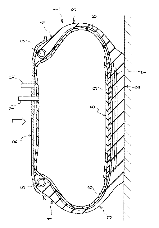
図1はこの発明の実施の形態を所定内圧の充填姿勢で示す横断面図であり、図中1は、チューブレスタイヤとして機能するタイヤの全体を示し、2は、円環形状をなすトレッドを、3は、トレッド2のそれぞれの側部から半径方向内方へ延びるサイドウォールを、そして4は、サイドウォール3の半径方向内端に連続させて設けたビード部をそれぞれ示す。
またこのタイヤ1は、それぞれのビード部4に配設したビードコア5間に伸びてトロイド状をなす、たとえばラジアルカーカス6を具えるとともに、ラジアルカーカス6のクラウン部の外周側に配設されて、トレッド2を補強するベルト7を具える。
【0015】
ここでは、かかるタイヤのリム組み姿勢で、その内側に、それとは別体をなす、円環形状の空気のう8を収納し、この空気のう8の、少なくとも外周部分に、不織布とゴムとの複合体よりなる少なくとも一枚の補強層9を接着等させて配設する。なおこの図に示すところでは、補強層9を空気のう8の外周面側に配設しているも、その補強層9を空気のう8の外周面側に代えて、もしくは加えて、内周面側に配設することもできる。
【0016】
またここでは、空気のう8の外周部分への補強層9の配設域wを、タイヤ1および空気のう8のそれぞれに所定の内圧P1およびP2を充填した姿勢の下で、トレッド2の内周面と対向するほぼ全域とし、空気のう8の最大幅Wのほぼ0.8倍としているも、その配設域は、図2に例示するように、空気のう外周部分から空気のう8の最大幅位置までの範囲とすることもできる。
【0017】
ここで、図2に示す場合には、図1に示す場合に比して補強層9の配設域が広くなることで、空気のうの若干の重量増加はあるものの、通常使用時及びランフラット走行時の空気のう形状のコントロールがより容易になる。
【0018】
なおここで、それぞれの内圧P1,P2は、
P2−P1≧0
の相対関係を満たすもの、より具体的には、
P2−P1=0〜200(kPa)
の条件を満たすものとすることが好ましい。
【0019】
ところで、このような補強層9において、不織布を形成するフィラメントは、20〜80mmの長さを有するものとし、より好ましく、そのフィラメントの弾性率Ef(GPa)の、そのフィラメントの密度ρ(g/cm3)に対する比を30以上とする。
【0020】
なお、図1、2に示すところにおいて、Rはリムを示し、V1,V2はそれぞれタイヤ1および空気のう8への圧力の給排を司るバルブを示す。
【0021】
このような安全タイヤは、前述したように、構造が簡単であり、製造およびリム装着がともに容易であるとともに、コストの低減および高い低燃費性を実現することができる。
【0022】
また、この安全タイヤにおいて、タイヤ1が正常であるときは、そのタイヤ1は、自身で荷重を支持しつつ負荷転動する。この場合、補強層9によって補強された空気のう8、とくにはそれの外周部分は、その全周にわたってトレッド内周面から間隔をおいて位置するので、その外周部分およびトレッド内周面のいずれにも不測の摩耗が生じることはない。そしてこのことは、不織布を形成するフィラメントの密度ρ(g/cm3)に対するそのフィラメントの弾性率Ef(GPa)の比を30以上とした場合により顕著である。
【0023】
これに対し、タイヤ1がパンク等することによって、そこから内圧が洩出した場合において、空気のう内圧P2とタイヤ内圧P1との圧力差が増加して、空気のう8に作用する引張力が、補強層9の耐張力を上回ったときには、その補強層9に、空気のう8の円周方向の伸長変形が生じ、これに伴って空気のう8が拡径変形する。
ここにおけるこのような拡径変形は、不織布を形成するフィラメントの長さを20〜80mmの範囲に選択することで、所期した通りにコントロールすることができ、また、その変形を空気のう8の全周にわたって均一にかつ円滑に行わせることができる。
【0024】
空気のうのかかる拡径変形は、図3に例示するように、とくにタイヤトレッドの接地域で、空気のう8の外周部分がトレッド内周面に密着して、荷重の支持を、タイヤ1から空気のう8に肩代わりできるようになるまで継続され、空気のう8は、図示の状態下で、荷重を支持した安全走行を長期間にわたって継続することができる。
【0025】
【実施例】
)
タイヤサイズを、315/60R22.5とした場合の安全タイヤにおいて、タイヤ内圧を850kPa、空気のう内圧を850kPaとした場合の、タイヤによって荷重を支持する通常走行時の耐久性、通常走行の後の空気のうの状態および、空気のうで荷重を支持するランフラット走行時の耐久性のそれぞれを求めたところ、表1および2に示す通りとなった。
【0026】
ここで通常走行時の耐久性は、ドラム耐久試験で、最大負荷能力に相当する質量を負荷し、60km/hの速度でタイヤに故障が生じるまでの走行距離を測定することにより求め、また、通常走行後の空気のうの状態は、X線を用いた非破壊内部検査により求めた。
そしてランフラット耐久性は、タイヤ内圧を大気圧としたパンク状態の下で、先の通常走行時の耐久性と同様の試験を行って求めた。
なお表中の指数値は大きいほどすぐれた結果を示すものとする。
【0027】
【表1】
【表2】
表1および2によれば、実施例1〜3はいずれも、通常走行耐久性およびランフラット耐久性をともに、比較例1に対して大きく向上させることができ、また、比較例4〜8に比して、空気のうを、摩耗から有効に保護し得ることが解る。
【0030】
【発明の効果】
かくしてこの発明によれば、空気のう、ひいては、安全タイヤを、一般的な材料の使用下で簡単な構造に構成することができ、また、その空気のうの製造および、リムへの装着をともに容易ならしめることができる他、重量の抑制下で、すぐれた低燃費性能を実現することができる。
しかもここではすぐれたランフラット耐久性をもたらすこともできる。
【0031】
加えて、不織布を形成するフィラメントの弾性率の、フィラメント密度に対する比を30以上に選択した場合に、通常走行時の耐久性をもまた大きく向上させることができる。
【図面の簡単な説明】
【図1】この発明の実施の形態を示す横断面図である。
【図2】この発明の他の実施の形態を示す横断面図である。
【図3】空気のうによる荷重の支持状態を示す横断面図である。
【符号の説明】
1 タイヤ
2 トレッド
3 サイドウォール
4 ビード部
6 ラジアルカーカス
7 ベルト
8 空気のう
9 補強層[0001]
BACKGROUND OF THE INVENTION
The present invention relates to a tire that can continue to run even if the internal pressure of the tire rapidly decreases, for example, due to puncture or the like.
[0002]
[Prior art]
Various types of run-flat tires or safety tires have been researched and developed in the past so that even if the tire is punctured, etc., it is possible to continue traveling safely for a considerable distance to a place where repair, reinforcement, etc. can be performed. For example, a run-flat tire in which the tube itself is devised, a sealant-coated tire, a filled tire, a core-embedded tire, and the like, such as a reinforcing tube, a multi-chamber tube, a filling tube, and a folding tube are known.
In recent years, Japanese Patent Application Laid-Open No. 7-276931 has reported a double-structured safety tire in which an inner tire smaller than the outer tire is placed inside the outer tire.
[0003]
[Problems to be solved by the invention]
However, the former conventional tires are difficult to make due to special manufacturing methods and auxiliary member materials, and are often difficult to mount and handle on wheel rims. In the multi-chamber type, the manufacture of the tube is very difficult and impractical, and for sealant-coated tires and filled tires, it is difficult to develop sealant injection methods and materials. Then, there was a difficulty in attaching the core to the rim.
Furthermore, it is difficult to manufacture mousse type safety tires such as sponge filling and elastic body filling, and it is also difficult to control and stabilize the shape.
[0004]
The latter safety tire described in Japanese Patent Application Laid-Open No. 7-276391 has a problem of low fuel consumption because the tire has a double structure and the tire becomes heavier.
[0005]
Therefore, the present invention is a safety tire that has a simple structure, is easy to manufacture and attach to a rim, is economical in terms of material, does not impair fuel efficiency, and exhibits excellent safety. The purpose is to provide.
[0006]
[Means for Solving the Problems]
A safety tire according to the present invention includes a tread, a pair of sidewalls and a bead portion, and a ring-shaped air bladder separate from the tire is accommodated inside the tire. While the outer peripheral surface of the air bladder is positioned away from the inner peripheral surface of the tread in a posture in which each of the air bladders is filled with a predetermined internal pressure, the expansion of the air bladder is reduced when the tire internal pressure is reduced to the atmospheric pressure. The outer peripheral surface of the air bladder is brought into close contact with the inner peripheral surface of the tread under radial deformation, and one or more reinforcing layers that form a composite of nonwoven fabric and rubber are disposed at least on the outer peripheral portion of the air bladder. The length of the filament forming the nonwoven fabric is set in the range of 20 to 80 mm, and the ratio of the elastic modulus E f (GPa) of the filament forming the nonwoven fabric to the density ρ (g / cm 3 ) of the filament is 30 or more One in which the.
[0007]
Here, the composite of nonwoven fabric and rubber means a single layer or laminated structure of nonwoven fabric impregnated with rubber. In this case, the composite preferably has a nonwoven fabric having a basis weight in the range of 10 to 300 g / m 2 in the rubber composition, and the filament forming the nonwoven fabric has a maximum diameter of 0.0001 to 0.2 mm. It is preferable to have.
[0008]
In the above safety tires, in particular, the structure of the air bladder is simple, and it is easy to manufacture and attach to the rim. Under this, it is possible to demonstrate excellent fuel efficiency.
[0009]
In addition, in this safety tire, before the tire that is assembled with the rim and filled with the predetermined internal pressure causes leakage of the internal pressure due to puncture or the like, the load can be sufficiently supported by the tire. Since the air bladder in the tire is also spaced from the inner circumferential surface of the tread over the entire circumference under filling with internal pressure, not only the inner circumferential surface of the tread, but also the air bladder, especially the outer circumferential portion, Unexpected wear is effectively prevented, and the air bladder can fully perform its original function described below with excellent durability.
[0010]
On the other hand, when the internal pressure is reduced to atmospheric pressure due to tire puncture or the like, the air bag is subjected to an expansion of the reinforcing layer disposed on the outer peripheral portion of the air bag due to the expansion deformation caused by the pressure difference between the inside and the outside. The tire itself expands and deforms, thereby closely contacting the inner surface of the tread that has been crushed and supporting the load supported by the tire instead of the shoulder of the air. In addition, safe continuous running can be realized.
By the way, in this safety tire, since the reinforcing layer is composed of a composite of a nonwoven fabric and rubber, the crossover structure of the nonwoven fabric filaments is reduced during the run-flat running as described above under the crushing deformation of the tire. It can be varied uniformly above to ensure more uniform expansion of the air bladder throughout.
[0011]
In addition, here, by controlling the length of the filament forming the nonwoven fabric in a range of 20 to 80 mm, the diameter expansion deformation of the air bladder when the tire internal pressure is lowered, and thus the expansion is controlled as expected, The expansion can be performed uniformly and smoothly over the entire circumference of the air bladder.
[0012]
In other words, when the length is less than 20 mm, the filaments are unconstrained by slight elongation deformation of the reinforcing layer, so that the restriction of the reinforcing layer to the air bag is limited before the air bag expands to its working state. After that, since the air bladder freely expands and deforms, it is difficult to specify the expansion mode and shape of the air bladder.
On the other hand, if the filament length exceeds 80 mm, the entanglement of the filament becomes too complex and dense, so that smooth deformation during expansion of the air bladder becomes difficult and uniform deformation over the entire circumference becomes difficult. Therefore, the stress of the air bag is prematurely damaged due to the stress concentration caused by the local expansion and deformation.
[0013]
Further, here, the ratio of the elastic modulus E f (GPa) of the filament forming the non-woven fabric to the density ρ (g / cm 3 ) of the filament, that is, E f / ρ is 30 or more, so that the normal running Ensures proper expansion of the air bag at the time.
In other words, when the ratio is less than 30, the elastic modulus of the filament becomes small, and it becomes difficult to sufficiently restrain the expansion of the air bag when the tire is normal. On the other hand, when the low elastic modulus is compensated by increasing the number of filaments, in other words, by increasing the density, the weight of the reinforcing layer is increased, the deformation restraining force against the air bladder is reduced, and the heat generation amount is also increased. Become.
[0014]
DETAILED DESCRIPTION OF THE INVENTION
Embodiments of the present invention will be described below based on the drawings.
FIG. 1 is a cross-sectional view showing an embodiment of the present invention in a filling posture with a predetermined internal pressure. In FIG. 1, 1 shows the entire tire functioning as a tubeless tire, 2 shows a tread having an annular shape,
Further, the
[0015]
Here, in such a tire rim assembly posture, a ring-
[0016]
In addition, here, the region w of the reinforcing
[0017]
Here, in the case shown in FIG. 2, the arrangement area of the reinforcing
[0018]
Here, the internal pressures P 1 and P 2 are
P 2 −P 1 ≧ 0
Satisfying the relative relationship of, more specifically,
P 2 −P 1 = 0 to 200 (kPa)
It is preferable to satisfy the above condition.
[0019]
By the way, in such a
[0020]
1 and 2, R represents a rim, and V 1 and V 2 represent valves for controlling supply and discharge of pressure to and from the
[0021]
As described above, such a safety tire has a simple structure, and can be easily manufactured and fitted with a rim, and can realize cost reduction and high fuel efficiency.
[0022]
In this safety tire, when the
[0023]
On the other hand, when the
Such a diameter expansion deformation here can be controlled as expected by selecting the length of the filament forming the nonwoven fabric in the range of 20 to 80 mm. Can be performed uniformly and smoothly over the entire circumference.
[0024]
As illustrated in FIG. 3, the diameter expansion deformation that causes the air bladder is particularly in the contact area of the tire tread, and the outer peripheral portion of the
[0025]
【Example】
)
For safety tires with a tire size of 315 / 60R22.5, the durability during normal driving when the tire internal pressure is 850 kPa and the air bladder internal pressure is 850 kPa, supporting the load by the tire, after normal driving Table 1 and 2 show the conditions of the air bladder and the durability during run-flat running that supports the load in the air bladder.
[0026]
Here, the durability during normal running is obtained by measuring a running distance until a tire breaks down at a speed of 60 km / h by loading a mass corresponding to the maximum load capacity in a drum durability test. The state of air bladder after normal running was determined by non-destructive internal inspection using X-rays.
The run-flat durability was obtained by performing a test similar to the durability during the previous normal running under a puncture state where the tire internal pressure was atmospheric pressure.
It should be noted that the greater the index value in the table, the better the result.
[0027]
[Table 1]
[Table 2]
According to Tables 1 and 2, all of Examples 1 to 3 can greatly improve both the normal running durability and the run-flat durability relative to Comparative Example 1, and Comparative Examples 4 to 8 In comparison, it can be seen that the air bladder can be effectively protected from abrasion.
[0030]
【The invention's effect】
Thus, according to the present invention, it is possible to construct a pneumatic tire, and thus a safety tire, in a simple structure under the use of general materials, and to manufacture the pneumatic bladder and attach it to a rim. In addition to being able to make both easy, it is possible to realize excellent fuel efficiency performance under weight control.
Moreover, excellent run-flat durability can be provided here.
[0031]
In addition, when the ratio of the elastic modulus of the filament forming the nonwoven fabric to the filament density is selected to be 30 or more, the durability during normal running can also be greatly improved.
[Brief description of the drawings]
FIG. 1 is a cross-sectional view showing an embodiment of the present invention.
FIG. 2 is a cross-sectional view showing another embodiment of the present invention.
FIG. 3 is a cross-sectional view showing a state in which a load is supported by an air bladder.
[Explanation of symbols]
DESCRIPTION OF
Claims (1)
空気のうの、少なくとも外周部分に、不織布とゴムとの複合体になる補強層を配設し、不織布を形成するフィラメントの長さを20〜80mmの範囲とするとともに、不織布を形成するフィラメントの弾性率Ef(GPa)の、そのフィラメントの密度ρ(g/cm3)に対する比を30以上としてなる安全タイヤ。A tire having a tread and a pair of sidewalls and a bead portion contains a ring-shaped air bladder that is separate from the tire, and is provided to each of the tire and the air bladder. In the internal pressure filling posture, the outer peripheral surface of the air bladder is positioned away from the inner peripheral surface of the tread, while the tire internal pressure is reduced to atmospheric pressure. A safety tire that closely contacts the outer peripheral surface of the tread with the inner peripheral surface of the tread,
A reinforcing layer that is a composite of a nonwoven fabric and rubber is disposed on at least the outer peripheral portion of the air bladder, and the length of the filament that forms the nonwoven fabric is in the range of 20 to 80 mm. elastic modulus E f (GPa), safety tires ing as a ratio more than 30 with respect to the density of the filaments ρ (g / cm 3).
Priority Applications (1)
| Application Number | Priority Date | Filing Date | Title |
|---|---|---|---|
| JP2000363336A JP4596633B2 (en) | 2000-11-29 | 2000-11-29 | Safety tire |
Applications Claiming Priority (1)
| Application Number | Priority Date | Filing Date | Title |
|---|---|---|---|
| JP2000363336A JP4596633B2 (en) | 2000-11-29 | 2000-11-29 | Safety tire |
Publications (2)
| Publication Number | Publication Date |
|---|---|
| JP2002166711A JP2002166711A (en) | 2002-06-11 |
| JP4596633B2 true JP4596633B2 (en) | 2010-12-08 |
Family
ID=18834460
Family Applications (1)
| Application Number | Title | Priority Date | Filing Date |
|---|---|---|---|
| JP2000363336A Expired - Fee Related JP4596633B2 (en) | 2000-11-29 | 2000-11-29 | Safety tire |
Country Status (1)
| Country | Link |
|---|---|
| JP (1) | JP4596633B2 (en) |
Families Citing this family (5)
| Publication number | Priority date | Publication date | Assignee | Title |
|---|---|---|---|---|
| WO2008146714A1 (en) * | 2007-05-24 | 2008-12-04 | Bridgestone Corporation | Safety tire |
| JP5139431B2 (en) * | 2007-08-02 | 2013-02-06 | 株式会社ブリヂストン | Safety tire |
| KR100982601B1 (en) * | 2009-08-19 | 2010-09-16 | 강흥묵 | Wheel having a multi-rim and multi-tire |
| US9144268B2 (en) | 2010-11-02 | 2015-09-29 | Nike, Inc. | Strand-wound bladder |
| WO2017153813A1 (en) * | 2016-03-11 | 2017-09-14 | Comet S.R.L. | Safety device for wheels |
Family Cites Families (5)
| Publication number | Priority date | Publication date | Assignee | Title |
|---|---|---|---|---|
| JPS642606U (en) * | 1987-06-26 | 1989-01-09 | ||
| FR2642371B1 (en) * | 1989-01-27 | 1991-12-27 | Hutchinson | AIR CHAMBER, IN PARTICULAR FOR A BICYCLE OR MOPED TYPE VEHICLE AND MANUFACTURING METHOD THEREOF |
| JPH06336103A (en) * | 1993-05-28 | 1994-12-06 | Yokohama Rubber Co Ltd:The | Wheel equipped with pneumatic safety tire |
| JP2002059719A (en) * | 2000-08-23 | 2002-02-26 | Bridgestone Corp | Safety pneumatic tire |
| JP2002172918A (en) * | 2000-09-29 | 2002-06-18 | Bridgestone Corp | Safety pneumatic tire |
-
2000
- 2000-11-29 JP JP2000363336A patent/JP4596633B2/en not_active Expired - Fee Related
Also Published As
| Publication number | Publication date |
|---|---|
| JP2002166711A (en) | 2002-06-11 |
Similar Documents
| Publication | Publication Date | Title |
|---|---|---|
| JP4723754B2 (en) | Variable stiffness wedge insert for run-flat tires | |
| JP5284307B2 (en) | Underlay structure for crown reinforcement | |
| KR20010013040A (en) | Runflat tire with improved carcass | |
| CN102216093A (en) | Vehicle Pneumatic Tires | |
| JP2017197176A (en) | Lightweight tires | |
| JP4237638B2 (en) | Pneumatic tire | |
| JP4308329B2 (en) | Run-flat tire with improved non-inflating handling | |
| JP4596633B2 (en) | Safety tire | |
| JP4686239B2 (en) | Pneumatic run flat tire | |
| JP3377448B2 (en) | Run flat tire | |
| US6843293B1 (en) | Variable-stiffness wedge insert for runflat tires | |
| CN114633586A (en) | Non-pneumatic tires | |
| JP4149672B2 (en) | Improved sidewall with insert structure for run-flat tires | |
| JP2004090807A (en) | Assembly of tire and rim | |
| JP4303424B2 (en) | Discontinuous ply for run-flat tire construction | |
| JP4256091B2 (en) | Safety tire pneumatic bladder and safety tire assembly | |
| JP3971913B2 (en) | Pneumatic bladder for safety tire | |
| JP2004090808A (en) | Safety tire | |
| JP4750544B2 (en) | Pneumatic bladders and safety tires for safety tires | |
| JP4009104B2 (en) | Safety tire with a gas-filled tube with reinforcement in a tubeless tire | |
| JP4571584B2 (en) | Pneumatic bladder for safety tire | |
| JP4724716B2 (en) | Pneumatic and safety tires for safety tires | |
| JP2005067363A (en) | Safety pneumatic tire | |
| JP7132172B2 (en) | pneumatic tire | |
| JP4256090B2 (en) | Pneumatic bladder for safety tire |
Legal Events
| Date | Code | Title | Description |
|---|---|---|---|
| A621 | Written request for application examination |
Free format text: JAPANESE INTERMEDIATE CODE: A621 Effective date: 20070906 |
|
| RD03 | Notification of appointment of power of attorney |
Free format text: JAPANESE INTERMEDIATE CODE: A7423 Effective date: 20070906 |
|
| A977 | Report on retrieval |
Free format text: JAPANESE INTERMEDIATE CODE: A971007 Effective date: 20100603 |
|
| A131 | Notification of reasons for refusal |
Free format text: JAPANESE INTERMEDIATE CODE: A131 Effective date: 20100608 |
|
| A521 | Request for written amendment filed |
Free format text: JAPANESE INTERMEDIATE CODE: A523 Effective date: 20100806 |
|
| TRDD | Decision of grant or rejection written | ||
| A01 | Written decision to grant a patent or to grant a registration (utility model) |
Free format text: JAPANESE INTERMEDIATE CODE: A01 Effective date: 20100831 |
|
| A01 | Written decision to grant a patent or to grant a registration (utility model) |
Free format text: JAPANESE INTERMEDIATE CODE: A01 |
|
| A61 | First payment of annual fees (during grant procedure) |
Free format text: JAPANESE INTERMEDIATE CODE: A61 Effective date: 20100921 |
|
| R150 | Certificate of patent or registration of utility model |
Free format text: JAPANESE INTERMEDIATE CODE: R150 |
|
| FPAY | Renewal fee payment (event date is renewal date of database) |
Free format text: PAYMENT UNTIL: 20131001 Year of fee payment: 3 |
|
| R250 | Receipt of annual fees |
Free format text: JAPANESE INTERMEDIATE CODE: R250 |
|
| LAPS | Cancellation because of no payment of annual fees |