JP4586525B2 - Virtual drum device - Google Patents
Virtual drum device Download PDFInfo
- Publication number
- JP4586525B2 JP4586525B2 JP2004368051A JP2004368051A JP4586525B2 JP 4586525 B2 JP4586525 B2 JP 4586525B2 JP 2004368051 A JP2004368051 A JP 2004368051A JP 2004368051 A JP2004368051 A JP 2004368051A JP 4586525 B2 JP4586525 B2 JP 4586525B2
- Authority
- JP
- Japan
- Prior art keywords
- controller
- cpu
- interface unit
- detects
- sensor
- Prior art date
- Legal status (The legal status is an assumption and is not a legal conclusion. Google has not performed a legal analysis and makes no representation as to the accuracy of the status listed.)
- Expired - Fee Related
Links
Images


Landscapes
- Electrophonic Musical Instruments (AREA)
- Selective Calling Equipment (AREA)
Description
この発明は、信号を送信するコントローラと受信した信号に基づいて処理を行う処理装置本体からなる処理装置において、コントローラの操作に対して行われる処理を切り替えることができる、バーチャルドラム装置に関する。 The present invention relates to a virtual drum device capable of switching processing performed in response to an operation of a controller in a processing device including a controller that transmits a signal and a processing device body that performs processing based on the received signal.
コントローラの操作に対して行われる処理を切り替える技術としては、特許文献1において、背面にキーの機能を設定することができるスイッチを設けたコントローラが開示されている。
上記技術はスイッチによってコントローラの機能を切り替える操作が煩雑であり、切り替え対象の機能が増えると、機能の切り替えに複数回の操作が必要となり熟練を要する。また、機能の切り替えにしか使われないスイッチを設ける必要がある。
この発明は、上記の事情を考慮してなされたものであり、その目的は、コントローラに方位を検出する磁気センサを具備することにより、コントローラの向きを変えるだけで機能を切り替えることができる、コントローラ機能の切り替え手段を有する処理装置を提供することである。
In the above technique, the operation of switching the function of the controller by the switch is complicated, and when the number of functions to be switched increases, a plurality of operations are required to switch the function, and skill is required. It is also necessary to provide a switch that can be used only for switching functions.
The present invention has been made in consideration of the above circumstances, and an object of the present invention is to provide a controller that can change the function only by changing the orientation of the controller by providing the controller with a magnetic sensor that detects the direction. It is to provide a processing apparatus having a function switching means.
この発明は上記の課題を解決するためになされたもので、本発明は、所定の信号を送信するスティック状のコントローラと、該コントローラからの信号に従って所定の処理を行う処理部と、ドラムを構成する複数の楽器の音を発生する音源と、からなるバーチャルドラム装置であって、前記コントローラは、磁界の強度を検出することにより方位を検出する方位センサと、加速度を検出する加速度検出部とを具備し、前記処理部は、前記方位センサにより検出された方位と演奏者による楽器種類の指示とにより、前記方位と発生すべき楽器の音との対応が予め設定されており、前記コントローラが、前記加速度検出部により検出された加速度の出力変化に基づき、音を発生するためのトリガがかかったことを検出すると、前記設定された方位と発生すべき楽器の音との対応に従って、前記トリガが検出された時に前記方位センサにより検出された方位に対応する楽器を特定し、特定した楽器の音を前記音源に発生させるように制御を行うことを特徴とするバーチャルドラム装置である。 The present invention has been made to solve the above problems, and the present invention includes a stick-like controller that transmits a predetermined signal, a processing unit that performs a predetermined process in accordance with a signal from the controller, and a drum. A virtual drum device comprising: a sound source that generates sounds of a plurality of musical instruments , wherein the controller includes an azimuth sensor that detects an azimuth by detecting the strength of a magnetic field, and an acceleration detection unit that detects acceleration. The processing unit is preset with a correspondence between the direction and the sound of the musical instrument to be generated, according to the direction detected by the direction sensor and the instruction of the instrument type by the performer. When detecting that the basis of the output change of the detected acceleration by the acceleration detecting section, took trigger to generate a sound, the set orientation In accordance with the correspondence between the sound to be generated musical instruments, the azimuth sensor by identifying the instrument corresponding to the detected azimuth, performs control so as to generate a sound of the specified instrument to the sound source when the trigger is detected This is a virtual drum device.
この発明によれば、現実としての打撃を伴なわないため、ヘッドホン等を併用する事で環境に対してサイレントなドラム演奏を可能とする。 According to the present invention, because it is not accompanied the blow of as reality, to allow a silent drum performance to the environment by a combination of headphones and the like.
以下、図面を参照し、この発明の実施の形態について説明する。図1は、この発明の第1の実施形態におけるゲーム機1の構成を示すブロック図である。
ゲーム機1は、コントローラ20とゲーム機本体30から構成される。コントローラ20は各種スイッチやジョイスティック等を有し、操作者が手に持ってゲームを操作するものである。
コントローラ20の地磁気センサ10は、図2に示すように、X軸、Y軸、Z軸における磁界の強度を検出することにより、コントローラ20の方位を検出する方位センサである。各軸の方向は、コントローラ20を正面に向けて持ったとき、Y軸は正面方向、X軸はY軸と直交する水平右方向、Z軸は上方であり、これらは互いに垂直に設定されている。X軸センサ11、Y軸センサ12、Z軸センサ13はGMR素子(巨大磁気抵抗効果素子)からなるセンサであり、それぞれX軸方向、Y軸方向、Z軸方向の磁界の強さに比例した値を出力する。
Embodiments of the present invention will be described below with reference to the drawings. FIG. 1 is a block diagram showing a configuration of a game machine 1 according to the first embodiment of the present invention.
The game machine 1 includes a
As shown in FIG. 2, the
切換器14は、X軸センサ11、Y軸センサ12、Z軸センサ13の出力を一定周期で切り換えて増幅器15に出力する。増幅器15は各センサの出力を増幅してA/Dコンバータ16に出力する。A/Dコンバータ16は入力信号をデジタル信号に変換し、インタフェース部17に出力する。インタフェース部17はCPU21からの要求に対してA/Dコンバータ16の出力値をバスライン26に出力する。
The
このようにして出力されたX軸センサ11、Y軸センサ12、Z軸センサ13の値をそれぞれSx、Sy、Szとしたとき、これらが取り得る値を座標空間上にプロットすると図3に示すような球面となる。すなわち、コントローラ20が方向を変えることによってSx、Sy、Szがとる値は図3の球面上のいずれかの点に対応するので、原点からその点への矢印の方向からコントローラ20の向いている方向を座標空間において把握することができる。
なお、コントローラ20の向いている方向を検出するには、水平方向に2軸の磁気センサを用いて方位を検出し、鉛直方向については傾きを検出する傾きセンサ、例えば重力を検知するセンサを用いて傾きを検出する構成としてもよい。
When the values of the X-axis sensor 11, the Y-
In addition, in order to detect the direction in which the
図1に戻り、操作部23は各種キーやジョイスティック等の操作子を有する。これにはコントローラ20の正面を設定する正面設定ボタンも含まれる。操作部23は、操作子に何らかの操作が行われたとき、例えばキーが押されたときに、この信号をバスライン26へ出力する。
Returning to FIG. 1, the operation unit 23 has operation elements such as various keys and a joystick. This includes a front setting button for setting the front of the
CPU(中央処理装置)21は、記憶部22に記憶されたプログラムを読み出して実行し、各部を制御する。また、地磁気センサ10の出力値を一定周期で取得して、インタフェース部24へ送信する。また、操作部23がバスライン26へ出力する信号を検知して、この信号をインタフェース部24へ送信する。
記憶部22は、CPU21のデータ、及び、CPU21が実行するプログラムを記憶する。
A CPU (central processing unit) 21 reads and executes a program stored in the storage unit 22 and controls each unit. Further, the output value of the
The storage unit 22 stores data of the
インタフェース部24は、ゲーム機本体30のインタフェース部37とコード25を介して通信し、CPU21から受信した信号をインタフェース部37へ送信する。なお、コントローラ20のインタフェース部24とゲーム機本体30のインタフェース部37の間は、コード25を介さずに無線で通信してもよい。
The
ゲーム機本体30のインタフェース部37は、コード25を介してコントローラ20のインタフェース部24から信号を受信すると、この信号をバスライン38へ出力する。HDD(ハードディスクドライブ)34は、ゲーム用プログラムを記憶する。ROM(リードオンリメモリ)32は、CPU31が各部を制御するための制御プログラムを記憶する。RAM(ランダムアクセスメモリ)33は、CPU31のデータ、及び、図4に示す各操縦パネルでのキー操作に対応する機能を示すキーの対応テーブルを記憶する。
CPU31は、HDD34のゲーム用プログラム、ROM32の制御プログラムを読み出して、ゲーム用プログラムの実行、及び、各部の制御を行う。また、インタフェース部37がバスラインへ出力した信号を検知して、これに対応する処理を行う。
ディスプレイインタフェース部36は、CPU31からの指示に基づきディスプレイ35に映像を表示する。
When the
The
The
ディスプレイ35は、例えばヘッドマウントディスプレイである。これはゴーグルやヘルメットのような形状をした表示装置である。例えば、操作者が頭部に装着すると左右の目のすぐ前にディスプレイが一つずつ取り付けられており、左右のディスプレイには操作者が表示される映像を立体的に感じるように少しずつ違った映像が表示されるようにするとよい。
図4は、操作者が頭部にヘッドマウントディスプレイを装着したときに、操作者がヘッドマウントディスプレイに表示される映像により、操作者には正面、左、右にそれぞれ操縦パネル100、101、102が実際に存在するように見えることを表す。それぞれの操縦パネルには、操作部23の操作子に対応する操作子が表示されている。これらの操縦パネルは、例えば宇宙船を操縦するゲームにおいてはコクピットの操縦パネルである。また、操縦パネルが表示される以外の部分には、宇宙船のコクピットの窓から見える外の景色の映像等が表示される。
The
FIG. 4 shows that when the operator wears a head-mounted display on the head, the operator displays the
なお、上記の操縦パネルは、常に3つとも表示しておくのではなく、ヘッドマウントディスプレイに方向を検出する手段をさらに備え、操作者が頭部を動かしてヘッドマウントディスプレイの方向を変えたときに対応する操縦パネルを表示するようにしてもよい。また、ディスプレイ35は上記のようなヘッドマウントディスプレイではなくテレビモニタとし、コントローラ20の向きにより操縦パネルを1つづつ切り替え表示してもよい。
The above control panel does not always display all three, but further includes means for detecting the direction of the head mounted display, and the operator moves the head to change the direction of the head mounted display. You may make it display the control panel corresponding to. The
次に図5及び図6を参照して上述したゲーム機1の動作を説明する。操作者はゲームスタート前に、図5に示す初期設定を行う。
操作者がコントローラ20を正面に向けて持ち、操作部23の正面設定ボタンを押すと、このボタンに対応する信号がバスライン26に出力される。CPU21はこの信号を検知してインタフェース部24へ送信する。また、CPU21は一定周期で地磁気センサ10の出力値を取得し、インタフェース部24へ送信する。インタフェース部24はこれらをゲーム機本体30のインタフェース部37へ送信する。
Next, the operation of the game machine 1 described above will be described with reference to FIGS. The operator performs the initial setting shown in FIG. 5 before starting the game.
When the operator holds the
ゲーム機本体30のインタフェース部37がコントローラ20から信号を受信すると、これをバスライン38へ出力する。CPU31はこれを検知し、ステップS20の判定を行う。この信号は正面設定ボタンが押されたことを示す信号であるので、判定結果が「Yes」となり、ステップS21へ進む。正面設定ボタンが押されていない場合はこれに対応する信号も送信されないので、この判定結果が「No」となり、ステップS20へ戻る。
When the
インタフェース部37がコントローラ20から送信された地磁気センサ10の出力値を受信すると、これをバスライン38へ出力する。CPU31はこれを検知して、地磁気センサ10の出力値を取り込む(ステップS21)。ここではSx、Sy、Szの出力値が(0,10,0)であったとして説明する。次に、CPU31は、その出力値が示す方向を正面として設定する、すなわち正面における地磁気センサ10の出力値としてRAM33に記憶する(ステップS22)。
When the
次に、CPU31は、正面、左、右の操縦パネル100、101、102に対応させる地磁気センサ10の出力値の範囲を設定する(ステップS23)。ここでは、図7において、正面の操縦パネル100に対応する出力値の範囲を−5≦Sx≦5,0≦Syとし、左の操縦パネル101に対応する出力値の範囲をSx≧5とし、右の操縦パネル102に対応する出力値の範囲をSx≦−5とする。この設定は、RAM33に記憶される。以上で初期設定は終了となる。
Next, the
次に、図6を参照して、ゲームを進行させるときのキー操作について説明する。操作者がヘッドマウントディスプレイであるディスプレイ35を装着してゲーム機1の操作部23においてゲームをスタートする操作を行うと、この操作に対応する信号が前述のようにしてコントローラ20からゲーム機本体30へ送信され、CPU31がこの信号を検知すると、ディスプレイインタフェース部36に対して、操縦パネルその他の映像の表示を指示する。例えば、宇宙船を操縦するゲームにおいては、図4のようなコクピットの操縦パネル100、101、102、及び、操縦パネルが表示される以外の部分には、宇宙船のコクピットの窓から見える外の景色の映像等が表示される。
また、CPU21は一定周期で地磁気センサ10の出力値を取得し、インタフェース部24へ送信する。インタフェース部24はこれをゲーム機本体30のインタフェース部37へ送信する。
Next, with reference to FIG. 6, the key operation when the game is advanced will be described. When the operator wears the
Further, the
操作者がコントローラ20の操作部23においてキー操作を行うと、この操作に対応する信号が前述のようにしてコントローラ20からゲーム機本体30のインタフェース部37へ送信される。インタフェース部37がこの信号を受信すると、これをバスライン38へ出力する。CPU31がこれを検知すると、ステップS30の判定において判定結果が「Yes」となり、ステップS31へ進む。何もキー操作が行われない場合はステップS30の判定結果が「No」となり、ステップS30へ戻る。
When the operator performs a key operation on the operation unit 23 of the
インタフェース部37がコントローラ20から送信された地磁気センサ10の出力値を受信すると、これをバスライン38へ出力する。CPU31はこれを検知して、地磁気センサ10の出力値を取り込む(ステップS31)。操作者がコントローラ20を正面に向けている場合は、Sx、Sy、Szの出力値は(0,10,0)またはこれに近い値となる。操作者がコントローラ20を正面から90°左に向けた場合は、磁界の方向が(10,0,0)またはこれに近い値となる。逆に正面から90°右に向けている場合は、磁界の方向が(−10,0,0)またはこれに近い値となる。CPU31は、地磁気センサ10の出力値が−5≦Sx≦5,0≦Syを満たす場合は正面の操縦パネル100、Sx≧5を満たす場合は左の操縦パネル101、Sx≦−5を満たす場合は右の操縦パネル102が操作対象であると判断する。
When the
CPU31は、ステップS30において取得したキー操作に対応する信号と、ステップS31において特定された操作対象の操縦パネルをもとに、RAM33に記憶されているキー対応テーブルを参照して、操作対象の操縦パネルにおいて操作されたキーに対応する制御を行う。(ステップS32)。CPU31はこの操作に対応させて表示する画像を生成して、ディスプレイインタフェース部36に対しディスプレイ35へのこの画像の表示を指示する。ここで表示される画像は、例えば、宇宙船を操縦するゲームにおいては、キー操作に応じて宇宙船が前方、左方向、右方向に向かって航行するに伴い変化するコクピットの外の景色の画像等である。
The
操作部23において終了操作があったときは、この操作に対応する信号が前述のようにしてコントローラ20からゲーム機本体30へ送信される。CPU31がこの信号を検知すると、ステップS33の判定結果が「Yes」となり、ゲームを終了する。終了操作がされていない場合は、ステップS30の判定結果が「No」となり、ステップS30へ戻る。
When there is an end operation in the operation unit 23, a signal corresponding to this operation is transmitted from the
なお、上記の動作において図5、図6に示すフローはゲーム機本体30のCPU31において行ったが、コントローラ20のCPU21で行う構成としてもよい。この場合、ステップS22において、正面とする方向の地磁気センサ10による出力値が設定されるのはコントローラ20の記憶部22となり、ステップS23において、各操縦パネルに対応する地磁気センサ10による出力値の範囲が設定され記憶されるのもコントローラ20の記憶部22となる。また、ステップS32において用いるキー対応テーブルはゲーム機本体30からコントローラ20に送信して記憶部22に記憶し、ステップS32の処理はコントローラ20のCPU21が、地磁気センサ10の出力値に対応する操作対象の操縦パネルを特定して、記憶部22に記憶されたキー対応テーブルを参照し、特定された操縦パネルにおいて操作されたキーに対応する信号をコントローラ20からゲーム機本体30へ送信する。ゲーム機本体30ではこの信号に対応する制御を行う。
なお、上記とは異なり、図5、図6に示すフローはゲーム機本体30のCPU31とコントローラ20のCPU21が処理を分担して行う構成としてもよい。
In the above operation, the flow shown in FIG. 5 and FIG. 6 is performed by the
Unlike the above, the flow shown in FIGS. 5 and 6 may be configured so that the
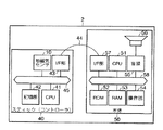
次に、この発明の第2の実施形態について説明する。図8は、この発明の第2の実施形態におけるバーチャルドラム装置2の構成を示すブロック図である。
バーチャルドラム装置2は、コントローラであるスティック40と本体50から構成される。
スティック40の構成は、前述のゲーム機1におけるコントローラ20と比較すると、操作部がない点が異なる。図9のように棒の一端に地磁気センサ10を取り付け、演奏者はこの逆端を握って通常のドラムスティックのように振る。
CPU41は、一定周期で地磁気センサ10の出力値を取得して、インタフェース部43へ送信する。また、CPU41は、地磁気センサ10の出力値を時系列で記憶部42に記憶し、トリガがかかったことが検出されたとき、すなわち、あらかじめ定めたある方向に一定値以上の加速度で加速され、一定時間内に逆方向に一定値以上の加速度がかかった時には地磁気センサ10の出力は特定の変化を示すため、その出力変化が検出されたときにドラムが叩かれたと判断して、インタフェース部43からトリガ検出を示す信号を送信する。なお、地磁気センサとは別に加速度センサ等を取り付け、加速度センサの出力の変化からトリガを検出してもよい。
記憶部42は、CPU41のデータ、及び、CPU41が実行するプログラムを記憶する。インタフェース部43、コード44の構成は、前述のゲーム機1のコントローラ20におけるものと同様である。なお、スティック40のインタフェース部43と本体50のインタフェース部57の間は、コード44を介さずに無線で通信してもよい。
Next explained is the second embodiment of the invention. FIG. 8 is a block diagram showing the configuration of the
The
The configuration of the
The
The
本体50の構成は、前述のゲーム機1におけるゲーム機本体30と比較すると、ディスプレイ35、ディスプレイインタフェース部36、HDD34がなく、操作部54、音源55、スピーカ56を有する点が異なる。もちろん、ディスプレイ35、ディスプレイインタフェース部36、HDD34を組み込んで構成してもよい。
CPU51は、ROM52に記憶されているプログラムを読み出して実行する。ROM52は、CPU51が実行する演奏プログラム、様々なドラムの音色を発生する楽音データ等を記憶する。楽音データはRAM53に記憶してもよい。RAM53は、CPU51のデータを記憶する。インタフェース部57の構成は、前述のゲーム機本体30におけるものと同様である。
The configuration of the
The
操作部54は、初期設定のための各ドラムの設定スイッチ、演奏スタート、演奏終了のスイッチ等を備える。音源55は、ROM52またはRAM53に記憶されている楽音データが入力されると楽音信号を生成し、スピーカ56へ出力する。これによりスピーカ56から楽音が発生する。なお、楽音データは音源55に格納し、音源55に対して音色を指示することとしてもよい。
The
次に図11及び図12を参照して、上述したバーチャルドラム装置2の動作を説明する。演奏者は演奏のスタート前に、図11に示す初期設定を行う。
演奏者がバーチャルドラム装置2を起動すると、スティック40のCPU41が一定周期で地磁気センサ10から取得した出力値を示す信号が、スティック40のインタフェース部43から本体50のインタフェース部57へ送信される。
Next, the operation of the above-described
When the performer activates the
演奏者はドラムを1つ決め、そのドラムを配置する方向に向けてスティック40を持ち、本体50の操作部54において、そのドラムの設定スイッチを押す。例えば、図10に示すようにドラムを配置するため、スティック40を正面に向けて、「タムB」の設定スイッチを押したとする。するとCPU51は操作部54のタムBの設定スイッチが押されたことを検知し、ステップS40の判定結果が「Yes」となり、ステップS41へ進む。設定スイッチが押されていない場合はこの判定結果が「No」となるので、ステップS40へ戻る。
The performer decides one drum, holds the
インタフェース部57がスティック40から送信された地磁気センサ10の出力値を受信すると、これをバスライン58へ出力する。CPU51はこれを検知して、地磁気センサ10の出力値を取り込む(ステップS41)。ここでは地磁気センサ10による出力値Sx、Sy、Szが(0,10,0)であったとすると、これを「タムB」の位置としてRAM53に記憶する。次に、ステップS43において、全てのドラムの設定が終了したか判定し、判定結果が「Yes」の場合は初期設定を終了する。まだ設定されていないドラムがある場合は判定結果が「No」となり、ステップS40へ戻る。
When the
上記のようにして、演奏者がすべてのドラムについてステップS40からステップS42を繰り返し、図10のようにドラムの位置を設定したとする。このときCPU51は、地磁気センサ10の出力値に対して、例えば、図13のように座標空間上に範囲を区切って、
シンバルAは、Sx≦−5,Sy≦0、
シンバルBは、Sx≧5,Sy≦0、
ハイハットは、Sx≦−6,Sy≧0、
スネアは、Sx≧6,Sy≧0、
タムAは、−6≦Sx≦−2,Sy≧0、
タムBは、−2≦Sx≦2,Sy≧0、
タムCは、2≦Sx≦6,Sy≧0、
というように各ドラムを対応させる。なお、図13は上記のように区切られた各々の範囲の球面上の境界線を省略している。以上で初期設定は終了となる。
なお、余った空間に他のドラム、例えばバスドラムを割り当ててもよいし、スティック40と同様の装置をさらに設け、演奏者の足に取り付けてスティック40とは独立に操作し、本体50へ信号を送信するように構成してもよい。
As described above, it is assumed that the performer repeats steps S40 to S42 for all the drums and sets the drum positions as shown in FIG. At this time, the
Cymbal A has Sx ≦ −5, Sy ≦ 0,
Cymbal B has Sx ≧ 5, Sy ≦ 0,
Hi-hat is Sx ≦ −6, Sy ≧ 0,
Snare is Sx ≧ 6, Sy ≧ 0,
Tom A is −6 ≦ Sx ≦ −2, Sy ≧ 0,
Tom B is −2 ≦ Sx ≦ 2, Sy ≧ 0,
Tom C is 2 ≦ Sx ≦ 6, Sy ≧ 0,
Each drum is made to correspond. In FIG. 13, the boundary lines on the spherical surface of each range divided as described above are omitted. This completes the initial setting.
Other drums, for example, bass drums, may be assigned to the extra space, or a device similar to the
次に、図12を参照して、演奏者がバーチャルドラム装置2によって演奏するときの動作について説明する。
演奏者がバーチャルドラム装置2を起動すると、スティック40のCPU41が一定周期で地磁気センサ10から取得した出力値を示す信号が、スティック40のインタフェース部43から本体50のインタフェース部57へ送信される。
演奏者が、本体50の操作部54の演奏スタートのスイッチを押し、スティック40を振る動作をすると地磁気センサ10の出力値は所定の変化を示すためCPU41はトリガがかかったことを検出し、トリガ検出を示す信号がスティック40のインタフェース部43から本体50のインタフェース部57へ送信される。インタフェース部57がこの信号を受信すると、これをバスライン58へ出力する。CPU51がこれを検知すると、ステップS50の判定結果が「Yes」となり、ステップS51へ進む。トリガ検出の信号が送信されていない場合はステップS50の判定結果が「No」となり、ステップS50へ戻る。
Next, with reference to FIG. 12, an operation when the performer performs with the
When the performer activates the
When the performer presses the performance start switch on the
インタフェース部57がスティック40から送信された地磁気センサ10の出力値を受信すると、これをバスライン58へ出力する。CPU51はこれを検知して、地磁気センサ10の出力値を取り込む(ステップS51)。
次に、ドラムの位置の初期設定に基づいて、その出力値に対応するドラムを特定し、そのドラムの音色を発生するよう音源55に指示する(ステップS52)。なお、ステップS50のトリガ検出において、スティック40の移動する加速度の大小を判定し、これに応じて音源55から発声するドラムの音の音量、音色、音の長さを変えてもよい。
When the
Next, based on the initial setting of the drum position, the drum corresponding to the output value is specified, and the
操作部54において演奏終了のスイッチが押された場合は、ステップS53の判定結果が「Yes」となり、演奏を終了する。終了スイッチが押されていない場合は、ステップS53の判定結果が「No」となり、ステップS50へ戻る。
なお、本発明はドラムに限定されるものではない。例えば操作者の向きを検出し、その向きに応じてキーボードやギター等、演奏する楽器を切り替えるようにすることもできる。
When the performance end switch is pressed on the
The present invention is not limited to the drum. For example, it is possible to detect the orientation of the operator and switch the musical instrument to be played, such as a keyboard or a guitar, according to the orientation.
この発明は、コントローラと本体からなる処理装置、ゲーム機等に用いられる。 The present invention is used for a processing device including a controller and a main body, a game machine, and the like.
1…ゲーム機、2…バーチャルドラム装置、10…地磁気センサ、11…X軸センサ、12…Y軸センサ、13…Z軸センサ、14…切換器、15…増幅器、16…A/Dコンバータ、17…インタフェース部、20…コントローラ、21…CPU、22…記憶部、23…操作部、24…インタフェース部、25…コード、26…バスライン、30…ゲーム機本体、31…CPU、32…ROM、33…RAM、34…HDD、35…ディスプレイ、36…ディスプレイインタフェース部、37…インタフェース部、38…バスライン、40…スティック、41…CPU、42…記憶部、43…インタフェース部、44…コード、45…バスライン、50…本体、51…CPU、52…ROM、53…RAM、54…操作部、55…音源、56…スピーカ、57…インタフェース部、58…バスライン、100、101、102…操縦パネル、200…シンバルA、201…ハイハット、202…タムA、203…タムB、204…タムC、205…スネア、206…シンバルB
DESCRIPTION OF SYMBOLS 1 ... Game machine, 2 ... Virtual drum apparatus, 10 ... Geomagnetic sensor, 11 ... X-axis sensor, 12 ... Y-axis sensor, 13 ... Z-axis sensor, 14 ... Switch, 15 ... Amplifier, 16 ... A / D converter, DESCRIPTION OF
Claims (1)
前記コントローラは、磁界の強度を検出することにより方位を検出する方位センサと、加速度を検出する加速度検出部とを具備し、
前記処理部は、前記方位センサにより検出された方位と演奏者による楽器種類の指示とにより、前記方位と発生すべき楽器の音との対応が予め設定されており、前記コントローラが、前記加速度検出部により検出された加速度の出力変化に基づき、音を発生するためのトリガがかかったことを検出すると、前記設定された方位と発生すべき楽器の音との対応に従って、前記トリガが検出された時に前記方位センサにより検出された方位に対応する楽器を特定し、特定した楽器の音を前記音源に発生させるように制御を行うことを特徴とするバーチャルドラム装置。 A virtual drum device comprising: a stick-shaped controller that transmits a predetermined signal; a processing unit that performs a predetermined process according to a signal from the controller; and a sound source that generates sounds of a plurality of musical instruments constituting the drum. ,
The controller includes an azimuth sensor that detects an azimuth by detecting the strength of a magnetic field, and an acceleration detection unit that detects acceleration ,
In the processing unit, the correspondence between the azimuth and the sound of the musical instrument to be generated is set in advance based on the azimuth detected by the azimuth sensor and the instruction of the instrument type by the player, and the controller detects the acceleration detection based on the output change of the detected acceleration by section detects that took trigger for generating sound according to the correspondence between the sound of the instrument to be generated and the set orientation, the trigger is detected A virtual drum apparatus characterized in that a musical instrument corresponding to the direction detected by the direction sensor is sometimes specified, and the sound of the specified musical instrument is generated in the sound source.
Priority Applications (1)
| Application Number | Priority Date | Filing Date | Title |
|---|---|---|---|
| JP2004368051A JP4586525B2 (en) | 2004-12-20 | 2004-12-20 | Virtual drum device |
Applications Claiming Priority (1)
| Application Number | Priority Date | Filing Date | Title |
|---|---|---|---|
| JP2004368051A JP4586525B2 (en) | 2004-12-20 | 2004-12-20 | Virtual drum device |
Publications (2)
| Publication Number | Publication Date |
|---|---|
| JP2006174856A JP2006174856A (en) | 2006-07-06 |
| JP4586525B2 true JP4586525B2 (en) | 2010-11-24 |
Family
ID=36729503
Family Applications (1)
| Application Number | Title | Priority Date | Filing Date |
|---|---|---|---|
| JP2004368051A Expired - Fee Related JP4586525B2 (en) | 2004-12-20 | 2004-12-20 | Virtual drum device |
Country Status (1)
| Country | Link |
|---|---|
| JP (1) | JP4586525B2 (en) |
Cited By (1)
| Publication number | Priority date | Publication date | Assignee | Title |
|---|---|---|---|---|
| US9406242B2 (en) | 2012-03-07 | 2016-08-02 | Casio Computer Co., Ltd | Skill judging device, skill judging method and storage medium |
Families Citing this family (11)
| Publication number | Priority date | Publication date | Assignee | Title |
|---|---|---|---|---|
| JP5216206B2 (en) * | 2006-12-01 | 2013-06-19 | 株式会社バンダイナムコゲームス | Program and game device |
| JP4668236B2 (en) * | 2007-05-01 | 2011-04-13 | 任天堂株式会社 | Information processing program and information processing apparatus |
| JP2010046471A (en) * | 2008-07-23 | 2010-03-04 | Sega Corp | Game device, game control method, game control program, and computer readable recording medium storing program |
| JP5379036B2 (en) * | 2010-02-09 | 2013-12-25 | 株式会社ソニー・コンピュータエンタテインメント | Information processing apparatus, control method therefor, program, and information storage medium |
| JP5088398B2 (en) * | 2010-06-01 | 2012-12-05 | カシオ計算機株式会社 | Performance device and electronic musical instrument |
| CN102314181B (en) * | 2010-07-08 | 2013-09-18 | 美新半导体(无锡)有限公司 | Direction control system and application thereof |
| KR101228529B1 (en) * | 2010-10-27 | 2013-01-31 | 포항공과대학교 산학협력단 | Musical brain fitness system |
| JP5338794B2 (en) | 2010-12-01 | 2013-11-13 | カシオ計算機株式会社 | Performance device and electronic musical instrument |
| JP6451926B2 (en) * | 2014-07-09 | 2019-01-16 | カシオ計算機株式会社 | Musical sound generation instruction device, musical sound generation instruction method, program, and electronic musical instrument |
| JP2018037034A (en) * | 2016-09-02 | 2018-03-08 | 株式会社タカラトミー | Information processing system |
| JP6546574B2 (en) * | 2016-10-06 | 2019-07-17 | 株式会社アルファコード | Game device, game control device and program for game |
Citations (7)
| Publication number | Priority date | Publication date | Assignee | Title |
|---|---|---|---|---|
| JPH0819062A (en) * | 1994-06-30 | 1996-01-19 | Mitsumi Electric Co Ltd | Remote controller |
| JP2000020054A (en) * | 1998-07-06 | 2000-01-21 | Yamaha Corp | Karaoke sing-along machine |
| JP2002251186A (en) * | 2001-02-23 | 2002-09-06 | Yamaha Corp | Music control system |
| JP2003111142A (en) * | 2001-09-28 | 2003-04-11 | Yamaha Corp | Portable telephone device and its controlling method |
| JP2004037646A (en) * | 2002-07-01 | 2004-02-05 | Yamaha Corp | Cellular phone device |
| JP2004166193A (en) * | 2002-09-27 | 2004-06-10 | Matsushita Electric Ind Co Ltd | Remote control device |
| JP2005171712A (en) * | 2003-12-15 | 2005-06-30 | Denso Corp | Remote controller |
-
2004
- 2004-12-20 JP JP2004368051A patent/JP4586525B2/en not_active Expired - Fee Related
Patent Citations (7)
| Publication number | Priority date | Publication date | Assignee | Title |
|---|---|---|---|---|
| JPH0819062A (en) * | 1994-06-30 | 1996-01-19 | Mitsumi Electric Co Ltd | Remote controller |
| JP2000020054A (en) * | 1998-07-06 | 2000-01-21 | Yamaha Corp | Karaoke sing-along machine |
| JP2002251186A (en) * | 2001-02-23 | 2002-09-06 | Yamaha Corp | Music control system |
| JP2003111142A (en) * | 2001-09-28 | 2003-04-11 | Yamaha Corp | Portable telephone device and its controlling method |
| JP2004037646A (en) * | 2002-07-01 | 2004-02-05 | Yamaha Corp | Cellular phone device |
| JP2004166193A (en) * | 2002-09-27 | 2004-06-10 | Matsushita Electric Ind Co Ltd | Remote control device |
| JP2005171712A (en) * | 2003-12-15 | 2005-06-30 | Denso Corp | Remote controller |
Cited By (1)
| Publication number | Priority date | Publication date | Assignee | Title |
|---|---|---|---|---|
| US9406242B2 (en) | 2012-03-07 | 2016-08-02 | Casio Computer Co., Ltd | Skill judging device, skill judging method and storage medium |
Also Published As
| Publication number | Publication date |
|---|---|
| JP2006174856A (en) | 2006-07-06 |
Similar Documents
| Publication | Publication Date | Title |
|---|---|---|
| JP5598490B2 (en) | Performance device, method and program | |
| JP6127367B2 (en) | Performance device and program | |
| JP6024136B2 (en) | Performance device, performance method and program | |
| US8858330B2 (en) | Music video game with virtual drums | |
| JP5966465B2 (en) | Performance device, program, and performance method | |
| US8609972B2 (en) | Performance apparatus and electronic musical instrument operable in plural operation modes determined based on movement operation of performance apparatus | |
| CN103295564B (en) | The control method of music performance apparatus and music performance apparatus | |
| JP4586525B2 (en) | Virtual drum device | |
| CN102568453B (en) | Performance apparatus and electronic musical instrument | |
| US20150356957A1 (en) | Drumstick controller | |
| JP2013190690A (en) | Musical performance device and program | |
| JP2013040991A (en) | Operator, operation method, and program | |
| JP5549698B2 (en) | Performance device, method and program | |
| US20190143205A1 (en) | Operation input system, operation input device, and game system | |
| JP4665811B2 (en) | Performance equipment | |
| JP4882443B2 (en) | Performance equipment | |
| JP6398291B2 (en) | Performance device, performance method and program | |
| WO2006011342A1 (en) | Music sound generation device and music sound generation system | |
| JP2006220938A (en) | Sound controller | |
| JP2013044889A (en) | Music player | |
| JP2011039248A (en) | Portable sound output device, computer program, and recording medium | |
| US20230326357A1 (en) | Information processing system and computer system implemented method of processing information | |
| JP5942627B2 (en) | Performance device, method and program | |
| JP2013195582A (en) | Performance device and program | |
| JP2014062945A (en) | Music playing device, music playing method, and program |
Legal Events
| Date | Code | Title | Description |
|---|---|---|---|
| A621 | Written request for application examination |
Free format text: JAPANESE INTERMEDIATE CODE: A621 Effective date: 20071024 |
|
| A131 | Notification of reasons for refusal |
Free format text: JAPANESE INTERMEDIATE CODE: A131 Effective date: 20100209 |
|
| A521 | Written amendment |
Free format text: JAPANESE INTERMEDIATE CODE: A523 Effective date: 20100412 |
|
| A131 | Notification of reasons for refusal |
Free format text: JAPANESE INTERMEDIATE CODE: A131 Effective date: 20100511 |
|
| A521 | Written amendment |
Free format text: JAPANESE INTERMEDIATE CODE: A523 Effective date: 20100708 |
|
| TRDD | Decision of grant or rejection written | ||
| A01 | Written decision to grant a patent or to grant a registration (utility model) |
Free format text: JAPANESE INTERMEDIATE CODE: A01 Effective date: 20100810 |
|
| A01 | Written decision to grant a patent or to grant a registration (utility model) |
Free format text: JAPANESE INTERMEDIATE CODE: A01 |
|
| A61 | First payment of annual fees (during grant procedure) |
Free format text: JAPANESE INTERMEDIATE CODE: A61 Effective date: 20100823 |
|
| R150 | Certificate of patent or registration of utility model |
Free format text: JAPANESE INTERMEDIATE CODE: R150 |
|
| FPAY | Renewal fee payment (event date is renewal date of database) |
Free format text: PAYMENT UNTIL: 20130917 Year of fee payment: 3 |
|
| LAPS | Cancellation because of no payment of annual fees |