JP4576740B2 - Window-shaped imaging display device and bidirectional communication method using the same - Google Patents
Window-shaped imaging display device and bidirectional communication method using the same Download PDFInfo
- Publication number
- JP4576740B2 JP4576740B2 JP2001103477A JP2001103477A JP4576740B2 JP 4576740 B2 JP4576740 B2 JP 4576740B2 JP 2001103477 A JP2001103477 A JP 2001103477A JP 2001103477 A JP2001103477 A JP 2001103477A JP 4576740 B2 JP4576740 B2 JP 4576740B2
- Authority
- JP
- Japan
- Prior art keywords
- imaging
- window
- display
- video
- display device
- Prior art date
- Legal status (The legal status is an assumption and is not a legal conclusion. Google has not performed a legal analysis and makes no representation as to the accuracy of the status listed.)
- Expired - Fee Related
Links
Images


Landscapes
- Two-Way Televisions, Distribution Of Moving Picture Or The Like (AREA)
- Transforming Light Signals Into Electric Signals (AREA)
- Transforming Electric Information Into Light Information (AREA)
- Testing, Inspecting, Measuring Of Stereoscopic Televisions And Televisions (AREA)
- Studio Devices (AREA)
Description
【0001】
【発明が属する技術分野】
本発明は、窓状撮像表示装置に関し、更に詳しく述べると、撮像機能と表示機能の両方の機能を備えた窓状の装置に関する。本装置は、離れた場所に存在する2つの空間の双方に設置して相互通信を行うことにより、それら2つの空間が恰も本装置の両側につながっているかのように感じさせる効果を作るのに用いることができる。
【0002】
【従来の技術】
従来、薄型の表示パネルを部屋の壁に掛けてその表示パネルの奥に実際に物が存在するように見せる試みがなされているが、それらは、画面表示が平面的であり現実感に乏しいものであった。
【0003】
現実感を増すために立体画像を映すようにすることも考えられるが、これらはいずれもカメラによって或方向から撮影した画像を表示しているものであるから、
その表示パネルを見る人の位置や方向により異なった画像を見ることができるようにはなっていない。あくまでもカメラで撮影されたものを見るだけである。
【0004】
また、図21に示すような立体視システム、立体テレビ等の立体画像表示装置も存在するが、これらは、もっぱら壁から被写体の像が浮き上がって見えるようにしたものであり、表示パネルの奥に空間が存在し、その表示パネルを介して見る人の居る空間と表示パネルの奥の空間がつながっているように見える効果は乏しい。しかも、この種の装置は立体視が得られる視者の位置範囲も限られている。そうして、この種の映像は不自然な映像となるので長時間見ていると心理的に疲れるものである。
【0005】
撮像装置としてカメラを使い表示装置として平面表示パネルを使ってテレビ電話を構成する従来の場合は、図22に示すように、通話を行う2つの端末の夫々にカメラと表示装置を設けて、カメラで撮影した画像を相手方に送り、相手方から送られてくる画像を自分の表示装置に映し出すようになっている。
【0006】
ところで、通話者は相手の顔を見ながら話をするので、表示画面に視線を合わせた状態で話をする。このため、話し手の前には表示装置がありカメラを置くスペースがないので、カメラは表示画面の上方等に設置する。その結果、画面に映る通話者の像は上方から映した像、即ち、うつ向き状態の画像となり通話をする者同士の視線が合わない。
【0007】
また、上記のように1対1の通話ではなくて、図23に示すように、複数人の参加者がいる2つの場所間で会話を行うTV電話会議システムがあるが、これは、上記テレビ電話を複数人で使うように拡張したものであり、送信側のカメラで撮影した画像を受信側に伝送し、それを受信側の表示パネルに表示するものである。従って、受信側で見る画像は送信側のカメラで撮影された画像であり、受信側の見る人の角度によって異なった画像が見えることはない。異なっているとすれば、それは受信側で見る画面の輪郭の相違くらいのものである。
【0008】
そうして、このTV電話会議システムの場合にも、会議参加者は表示画面の方を見ており、カメラは表示画面の外側の適当な場所に設置されるので、受信側で見る人と視線が合わず不自然である。
【0009】
これを改良したテレビ電話システムとして、図24に示すようなシステムが開発された。このシステムは、表示装置の前にハーフミラーを置いて、話し手が表示装置に映った聞き手の顔を見た状態で話し手の顔から来る光をハーフミラーで分離してカメラに導いて撮影するものである。
【0010】
こうすることにより、通話者はお互いに相手と視線を合わせながら通話できるが、ハーフミラーを設けなければならないので装置が複雑になり大型になるという欠点がある。
また、ハーフミラーは図示のように方向が限定されるので表示画面の中央位置から見る場合には良く機能するが画面の斜め横方向から見た場合には所期の機能を発揮しない。
【0011】
上記ハーフミラーを使う表示装置に変わる装置として、撮像機能を有する多数の撮像素子を設けた撮像面体と、表示機能を有する多数の表示素子を設けた画像表示面体とを平面的に重ね合わせて複合一体化した撮像表示装置が開発され、特開平1−280978号公報に記載されている。
【0012】
上記撮像表示装置は、撮像素子を図25に示すようなマトリックス状に配列した撮像面体と表示素子を同様にマトリックス状に配列した画像表示面体を、撮像素子と表示素子が光路方向で重ならないように横方向の位置を調整して、重ね合わせて図26に断面図として示すような構造としたものである。この例では、撮像面体が画像表示面体の上に形成されており、外部から入射した光は収束レンズ体によって収束され撮像素子上に投射される。また、液晶等の光スイッチで成る表示素子を透過した光は撮像素子の間を通過して出射される。
【0013】
この撮像表示装置は、画像表示面体と撮像面体とが平面的に均等に複合一体配列されているので、視線の不一致は起こらない。また、表示素子1つに対して撮像素子1つを対応させて設けることにより、撮影側と表示側の画面の解像度を一致させることができる。
【0014】
【発明が解決しようとする課題】
上記のとおり、従来の表示装置は、撮影現場に置かれたカメラで撮影したカメラ視野内の映像信号を他の場所に置かれた表示装置に伝送して表示させるだけの情報伝送システムであったため、見る側の人間の位置や角度が変化したとしても表示される映像に変化はなく、視者は絵画を見ているような感覚を受けるという欠点がある。
【0015】
上記の現状に鑑み、本発明の第1の課題は、離れた空間にそれぞれ設置された2つの窓状撮像表示装置を通信回線で接続して、離れた空間同士が一つの窓を通してつながっているように感じさせる効果を生む装置を提供することにある。
【0016】
本発明の第2の課題は、上記カメラで撮影した映像を表示装置に表示する場合のように、カメラの視野に入った映像を表示画面に映し出し、視者はその画面を見るだけという一方的な動作による表示ではなく、上記窓状撮像表示装置のディスプレイ・パネル(表示画面)を見る人間が位置や角度を変えることによって送られて来ている映像の中から見ようとする映像を選択して見ることができるようにして、よりリアル感のある映像信号伝送を可能にすることにある。また、ディスプレイ・パネルの大きさや形状、配置場所に応じて非常に幅広い応用が可能な装置を得ることにある。
【0017】
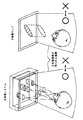
このことを更に明確に理解するために、図1を参照して本発明によって実現しようとする窓状撮像表示装置を説明する。同図に示すように本発明の窓状撮像表示装置を離れた2つの場所に各1つ設置し通信回線で接続して相互通信をおこなうと、図示のようにAが見る画像とBが見る画像、Cが見る画像は全て異なり、丁度窓ガラスを通して窓の向こうにある物を見ているようになる。
【0018】
上記の例では、場所W1に居る3人の人(A,B,C)が場所W2にある物D,E,Fを見る場合についての説明したが、これは、例えば重要文化財等の展示品を離れた部屋の中に保管しておき展示会場で本窓状撮像表示装置を使って見れるようにする場合に応用できる。この場合、視者は場所W1にのみ居るので1方向通信となるから、場所W2に設置する装置は撮像専用のパネル装置でよく、場所W1に設置する装置は表示専用のパネル装置にすることもできる。
【0019】
場所W1だけでなく場所W2にも人が居て場所W1を見られるようにするには、双方に撮像と表示の機能を持つ装置設置する必要がある。そのような場合として、
図27を参照して下記に説明するようなTV電話会議システムがある。
【0020】
図22、図23を参照して上記に説明したように、カメラを設置するテレビ電話やテレビ会議システムにおいては、カメラを設置する場所の都合から、テレビを通して会話を行う利用者同士の視線がずれてしまうと言う問題があった。
また、上記会話者の視線がずれてしまうという欠点を克服するものとして、上記のとおり撮像と表示の両方の機能を兼ね備えた撮像表示装置が提案されているが、この装置を使っても、光の方向を識別することはできないので、撮像素子群によって撮影された映像は撮像表示装置に入る光によって決まる映像であり、見る側の人の位置や角度によって見える範囲が異なるものではない。
【0021】
本発明の第3の課題は、図27に示すように、TV電話会議システムにおいて、場所W1に居る出席者A、B,Cが、場所W2に居る会議出席者D,E,Fを見るとき、夫々自分の座っている席から見える独自の視野を持つことができ、その逆に場所W2に居る会議出席者D,E,Fも場所W1に居る会議出席者についての独自の視野を持つことができる窓状撮像表示装置を提供することにある。
【0022】
上記のTV電話会議システムにおいて、会議出席者の全員が全員を見渡せるようにするには、大規模な窓状撮像表示装置を必要とするが、技術的又は経済的にそのようなことが許されない場合でも、本発明の窓状撮像表示装置は大いに効果を発揮する。
【0023】
図28を参照して、このことを説明する。場所W1に居る人が1人であってもその人の顔の向く方向や視線が分かると自然さが非常に増すものである。例えば図示のように、AがBの方向を見ているときにはAもBも自分の正面に相手の姿が見える。この時EはBの方を向いているAの姿を見ることができる。その状態から、AがEの方向を見るとAもEも自分の正面に相手の姿を見ることができるが、今度はBはEの方向を向いているAの姿を見ることになる。
【0024】
AがBと話している時にBの方を向いているということは、離れた場所にいるAとBが本発明の窓状撮像表示装置を通してお互いに相手を見ているような感覚を与え自然な感じを与えるものである。
【0025】
本発明の第4の課題は、上記窓状撮像表示装置を通信端末装置として設置するだけで、その場所の3次元情報を取り込むことができることを利用して、それらの情報を保存し、再生できるコンテンツを容易に作成することができるようにすることにある。
【0026】
本発明の他の課題は、音声、温度や湿度、ディスプレイ上の圧力や、熱分布、匂い等、人間が空間を認知するために利用する媒体の情報を映像と同時に伝送することで、よりリアルに空間をつなぐことを可能にする装置を得ることにある。
【0027】
【課題を解決するための手段】
上記課題を解決するために、本発明は、下記の手段を備えた窓状撮像表示装置、及びそれを用いた双方向通信方法を提供する。即ち、
平面基板の表面全体に亘って多数の撮像素子と表示素子が一様に分布するように形成され、該撮像素子によって入射光の少なくとも輝度と方向を検出し、該表示素子から入射光が直進するように見える方向に入射光に比例した輝度の出射光を出射するようにした撮像表示パネルと、
上記撮像表示パネル上の多数の撮像素子によって受光した映像情報に基いて映像信号を発生するとともに、他の撮像表示パネルから受信した映像信号に基いて多数の表示素子に供給する映像情報を発生する映像インターフェイス回路と、
上記映像インターフェイス回路から送られてくる信号を伝送回線上へ送信し伝送回線から受信した映像信号を上記映像インターフェイス回路へ送る信号送受信手段とを備えた窓状撮像表示装置を提供する。
【0028】
また上記の窓状撮像表示装置において、上記撮像表示パネルの各撮像素子が半球型突出面上に形成された所定数の撮像素子で構成した撮像素子集成体で成り、該半球型突出面上の当該撮像素子の位置によって入射光の方向が判別できるようになっており、
上記表示素子が各々半球型突出面上に形成された上記撮像素子集成体と同じ数の表示素子で構成した表示素子集成体で成り、該半球型突出面上の表示素子の位置によって出射光の方向を指定できるようになった窓状撮像表示装置も提供する。
【0029】
上記の窓状撮像表示装置において、該装置が更に、立体音声入出力手段及び該音声入出力の信号処理を行う音声インターフェイス手段と、
上記映像信号と上記音声信号を混合して複合映像信号を生成する信号処理手段とを備えた窓状撮像表示装置も提供する。
【0030】
更にまた、上記の窓状撮像表示装置において、該装置が更に、環境情報入出力手段及び該環境入出力手段により入力し又はそこへ出力する信号の信号処理をする環境情報インターフェイス手段を備えた窓状撮像表示装置も提供する。
【0031】
本発明の別の観点に従えば、平面基板の表面全体に亘って多数の撮像素子と表示素子が一様に分布するように形成され、該撮像素子によって入射光の少なくとも輝度と方向を検出するようにした撮像パネルと、
上記撮像パネル上の多数の撮像素子によって受光した映像情報に基いて映像信号を発生する映像インターフェイス回路と、
上記映像インターフェイス回路から送られてくる信号を伝送回線上へ送信する信号送信手段とを備えた窓状撮像パネル装置と、
平面基板の表面全体に亘って多数の表示素子が一様に分布するように形成され、該表示素子から上記入射光が直進するように見える方向に入射光に比例した輝度の出射光を出射するようにした表示パネルと、
上記撮像パネルから伝送回線を介して送られてきた映像信号を受信し、該受信した映像信号に基いて多数の表示素子に供給する映像情報を発生する映像インターフェイス回路と、を備えた窓状表示パネル装置と、を備えた窓状撮像表示装置を提供する。
【0032】
本発明はまた、平面基板の表面全体に亘って多数の撮像素子と表示素子が一様に分布するように形成され、該撮像素子によって入射光の少なくとも輝度と方向を検出し、該表示素子から入射光が直進するように見える方向に入射光に比例した輝度の出射光を出射するようにした撮像表示パネルと、
上記撮像表示パネル上の多数の撮像素子によって受光した映像情報に基いて映像信号を発生し、他の撮像表示パネルから受信した映像信号に基いて多数の表示素子に供給する映像情報を発生する映像インターフェイス回路と、
上記映像インターフェイス回路から送られてくる信号を伝送回線上へ送信し伝送回線から受信した映像信号を上記映像インターフェイス回路へ送る信号送受信手段とを備えた窓状撮像表示装置を離れた2以上の場所の夫々に設置し、伝送路を通して双方向映像データ通信を行う方法であって、
送信側の窓状撮像表示装置の撮像素子で被写体から来る光の位置と方向を検出して受信側に送り、受信側では、送信側から送られてくる映像信号の中のビューアの位置と窓状撮像表示装置の位置との関係で決まる視野の映像を見るようにする双方向通信方法も提供する。
【0033】
【発明の実施の形態】
本発明の窓状撮像表示置の一実施形態を、図面を参照して、下記に説明する。
図1は、本発明の窓状撮像表示装置の外観及び使い方を示す。同図に示す例では説明を分かり易くするために、壁で仕切られた隣接する2つの部屋の壁面の同じ位置に背中合わせになるように本装置を設置した場合を示している。一方の部屋の中には、撮影する対象物D,E,Fが置かれており、この対象物を本装置が撮影するようになっている。
【0034】
また、隣の部屋にはビューア(観察者)が複数人(A,B,C)いて複数の位置から本装置をみることができるようになっている。後述するように、背中合わせに配置した2つの窓状撮像表示装置は、一種の窓を形成し、この窓をとおして光が透過するように見えるように撮影し表示できるので、観察者A,B,Cはそれぞれ物体F,E,Dを自分の視線を向けた方向にみることができる。
【0035】
このような効果を得るための条件としては、図2に示すように、離れた場所W1とW2に設置された2つの窓状撮像表示装置の間で相互通信を行うことにより、互いに相手方の情報が得られるようにし、ビューアの位置によって相手方から送られてくる情報の中の当該ビューアによって選択された範囲の情報を得るようにすることである。
【0036】
同図において、場所W1に居るビューアAは通信端末装置T1として設置された窓状撮像表示装置を該装置の左側から覗く位置に立っており、この位置から窓状撮像装置を見た場合に窓状撮像表示装置の右側の情景が見えるようにすれば、ビューアAは窓越しに窓の向こうにある情景を見ているような感覚を得るであろう。
【0037】
同様にして、ビューアBについてもビューアCについても、場所W1の彼らが立っている位置から窓状撮像表示装置T1を見たときに、場所W2の情景が丁度窓ガラスを通して窓の向こうにある情景を見ているように窓状撮像表示装置に表示されればビューアB,ビューアCは窓状撮像表示装置を見て窓の向こうの情景を見ている感覚を得るであろう。
【0038】
この様子を下記に更に詳しく説明する。一般に窓ガラスを通して反対側にある物を見る場合、図3に示すとおり、窓ガラス面の位置(x,y)に角度(θ゜,φ)で入射した光は、そのパネルの裏面の同じ位置から角度(180゜−θ゜,180゜−φ゜)で出射するようになっている。
【0039】
従って、この窓ガラスと同じ窓状パネルを作ろうとすれば、撮像側のパネル面上の全ての点について、様々な方向から来る(即ち、上記θとφの種々の値に対する)光の少なくとも輝度(より自然さを出すためには色)についての情報を取り込み、それらの情報を表示側に伝送し、表示側パネル面上の対応する位置から入射角と180゜位相のずれた光を対応する輝度(及び色)で出射するようにパネルを形成すればよい。
【0040】
図4は、上記の条件を採り入れた本発明の窓状撮像表示装置の基本構成を図解したものである。入射光はパネル面に角度(θ゜,φ゜)で入射するが、この角度が変わると撮像素子群でなる半球型突出面の中の当該光が当たる撮像素子が異なるようにすることにより、入射光の方向を検出することができる。表示側パネル面上では対応する位置の表示素子群でなる半球型突出面上の対応する表示素子から対応する輝度(及び色)の光を出射させるようにすればよい。
【0041】
上記窓越しに物を見る感覚を与える装置について、下記にその構成と動作を説明する。ここでは、説明を分かり易くするために、2次元的に説明する。
図5に示すように、2つの窓状撮像表示装置を背中合わせに重ねて置いた状態で、一方の面に入射した光が他方の面から直進して出ていくようになるようにすればガラスを通して物を見ている感覚が得られる。換言すると、入射光の入射角と出射光の出射角が等しくなるようにすることである。窓ガラスを透して光りが透過する場合には光の入射位置と出射位置がほぼ等しいが、本装置においては、相対位置のみが重要であって絶対位置は必ずしも一致する必要はない。ただし、入射光と出射光の位置が視覚的に一致するように調整しておくことが必要である。
【0042】
2つの窓状撮像表示装置の間は通信線路でつながれていて、信号伝送により一方の装置の面に入射した光の情報が他方の装置の表示面に伝えられるようになっていて、これら2つの装置の中を光が透過するわけではないから、2つの窓状撮像表示装置は、上記のように壁面に背中合わせして設置する必要はなく、全く離れた別の部屋の壁に設置されていてもよい。また、一方が室内の壁に設置され、他方が家の外壁に設置されてもよい。
【0043】
図5に示すような現象が得られる本発明の窓状撮像表示装置の撮像表示パネルについて、図面を参照して、下記に説明する。
図6は、撮像表示パネル上の撮像素子と表示素子の配列を例示したものである。
(a)は、1列毎に撮像素子と表示素子を交互に配列したものである。
(b)は、撮像素子と表示素子を1行毎に並べて千鳥状に配列したものである。
(c)は、(b)と同じ配列であるが撮像素子及び表示素子の形状が6角形になっているところが(b)と異なる。
【0044】
このように、パネル上に撮像素子と表示素子とを一様に配列することにより、このパネルは撮像装置としての機能を備えるとともに表示装置としての機能も備えており、これを光学的に見ると入射光を受け取り、出射光を出す機能を有することになる。
【0045】
図7は、上記撮像表示パネルを2枚背中合わせにして配置したものを示し、上側のパネルについては撮像素子が形成されている部分を示し、下側のパネルについては表示素子が形成されている部分を示している。撮像素子も表示素子も同じ大きさの半球型の突出面の表面に形成されている。
【0046】
今、入射光が同図に矢印で示すように右上方から左下方に向かって入ると、撮像表示パネルの半球型突出面上の右方向の対応する撮像素子に入射する。入射光の当たる位置は半球型突出面に番号(アドレス)を付けておくことにより検出することができ、入射角度はその突出面上の撮像素子の位置によって検出することができる。
【0047】
同図においては、上側にk行j列にマトリックス配列された撮像素子群を構成する半球型突出面のa行目の(b−1)、(b)、(b+1)列目の突出面Ca1〜Cayが描かれている。下側にはk行j列マトリックス配列された表示素子群を構成する半球型突出面のa行目の(j−b+2)、(j−b+1)、(j−b)列目の突出面La1〜Layが描画されている。配列順序は上側が左から右に増加するアドレスとした場合には下側が右から左に向かって増加するアドレスとする。入射光と出射光の対応関係は時間遅れ分だけずらすのがよい。
【0048】
上記の窓状撮像表示パネル装置は、半球型の突出面上に複数の撮像素子を形成して成る撮像素子集成体と半球型の突出面上に複数の表示素子を形成して成る表示素子集成体を交互に配列し、隣接する撮像素子集成体と表示素子集成体が対をなすようにしたものである(これを2素子タイプとよぶ)が、図8を参照して下記に説明する窓状撮像表示パネル装置は、1つの半球型突出面上に撮像素子と表示素子の両方を形成したもの(撮像表示素子集成体)をマトリックス配列した撮像表示パネル装置であり(これを1素子タイプという)、2素子タイプと同様に構成できる。
【0049】
同図において、マトリックスはk行j列で構成されているものとし、
1<a<k、1<b<jの関係になっている。また、1つの半球型突出面上にm段に形成されたCCDの或段をcで表すとき、1<c<mである。c段における円周方向の位置をdc とすると、1<dc <nc で表される。
ここで、nx は偶数とし、n1 =1(1段目)、nc =4c−2(c段目)、nm =n(m段目)とする。
【0050】
図9は、上記2素子型の窓状撮像表示装置のパネル上に形成される半球型突出面の1つを詳細に示したものである。同図(a)に示すように、本半球型突出面上にはCCD等によって複数の撮像素子が形成されており、これらのCCD撮像素子は半球の頂部と底部の間に階層的に配列され、頂部は1つのCCDで形成され、底部は入射光の方向をどのくらい細かく検出するかの解像度によって決まる数nのCCDで形成する。頂部と底部の間の中間段は1個からn個の間で順次段階的に増加する数とする。
【0051】
同図(b)は、半球型突出面の断面を示す。半球型突出面の表面にはCCDが形成され、その外側がレンズを形成する光導体の形成された層で覆われている。CCDの面にほぼ垂直に入射した光は当該CCDに導かれるが斜め方向から入射した光は当該CCDに殆ど達しないようになっている。これにより、どのCCDで受けたかによりその光の来た方向がわかるようになっている。
【0052】
同図(c)は、(a)のCCD配列を平面的に展開して示したものである。このCCD配列の動作については後で詳しく説明するが、ここで簡単に説明すると、m段に構成されたCCDの内容は順次後段へシフトされ、最後段であるm段のCCDの内容がシフトレジスタに転送され該シフトレジスタから直列に外部に出力される。この時m−1段のCCDの内容はm段にシフトされているので、次にm−1段のCCDの内容がm段を通してシフトレジスタに転送されて、そこから直列に出力される。
【0053】
図10は、上記2素子型の窓状撮像表示装置のパネル上に形成される半球型突出面の他の1つを詳細に示したものである。同図(a)に示すように、本半球型突出面上にはLCD(液晶)表示素子が形成されている。この半球型突出面は上記図9を参照して説明したCCDの配列と同一形状、同一寸法の半球型突出面上に上記CCDと同一数のLCDを対応位置に形成したものである。
【0054】
LCDスイッチを通過した光は同図(b)に示すように直進し、従って、どのLCD素子から出た光であるかによってその光の進む方向が特定される。同図(c)は表示素子(LCD)の駆動回路を示す。レジスタRG1に駆動する表示素子の位置データをセットし、レジスタRG2に走査データをセットする。
【0055】
図11は、1つの半球型突出面上に撮像素子と表示素子の両方を搭載した撮像素子と表示素子の集成体を示す。この撮像素子・表示素子集成体は、半球型突出面にLCD等で表示素子を形成し、その上を光透過性の層で覆い、その上に下層の表示素子と重ならないようにCCD等で撮像素子を形成し、隣接する撮像素子と表示素子を一対の素子として扱うようにしたものである。
【0056】
ここで、図12を参照して、撮像素子集成体から電荷を読み出す方法を説明する。読み出し順序は最下段の撮像素子を最初に読み出し順次上方の段の撮像素子の内容(電荷)を読み出し最後に半球頂部の撮像素子の電荷を読み出すものとする。従って、時刻T1ではm段目のn個の素子の内容をシフトレジスタに並列に読み出し、上段の素子の内容を順次下段へ並列にシフトする。
【0057】
時刻T2ではm−1段目のn−k個(但しkはm段目に比べて減少した素子の数)の撮像素子からm段にシフトしてきている電荷をシフトレジスタに並列に読み出す。この方法で時刻Tm−1には2段目の素子からm段目にシフトされている電荷をシフトレジスタに読み出し、時刻Tmには1段目の1個の素子からの電荷がシフトレジスタに読み出される。
【0058】
1つの半球型突出面上に形成された1組の撮像素子(これを撮像素子集成体ということにする)から電荷の読み出しが終わると引き続き次の撮像素子集成体から電荷を読み出す。この仕方で時間t1に第1行のx個の撮像素子集成体から電荷信号を読み出し、次の時間t2に第2行のx個の撮像素子集成体から電荷信号を読み出し、以下同様にして、時間tyに第y行のx個の撮像素子集成体から電荷信号を読み出す。
こうして読み出した電荷信号は1フレームの信号として信号処理され受信側(即ち、表示する側)の装置に伝送される。
【0059】
次に、図13を参照して、表示素子集成体(半球型突出面上に形成された1組の表示素子)に表示信号を供給する方法について下記に説明する。表示素子集成体はx列y行にマトリックス配列されており、送信されてくる信号は1行1列〜1行x列、2行1列〜2行x列、・・・y行1列〜y行x列の順で送られてくるので、この順序で開くゲート配列を設け、各表示素子集成体に表示する画像信号が配向されるようにする。
【0060】
上記の方法で1つの表示素子集成体に配向された信号は、m段、(m−1)段、・・・2段、1段の順番で、各段のn個の角度情報を持つ信号として入力すると共に、それに同期して表示する段を指定することにより、撮像時と同じ画像を表示することができる。
【0061】
上記においては、半球型突出面上に形成された撮像素子群で成る撮像素子集成体、表示素子集成体及び撮像素子・表示素子集成体について構造と動作を説明したが、これらの素子集成体の窓状撮像表示装置上の配列を図14に示す。
撮像表示パネル上に配列する撮像素子集成体及び表示素子集成体は、2素子タイプ(撮像素子集成体と表示素子集成体が別々に形成されたタイプ)と1素子タイプ(撮像素子と表示素子が1つの集成体として形成されたタイプ)があるが、同じタイプの素子集成体配列からなる2つの表示パネルを離れた2つの場所W1,W2に設置し、データ通信装置を介して双方向通信を行うようにする。
【0062】
上記のように配列された撮像素子集成体からの情報の読み出し及び表示素子集成体による表示について、図15を参照して下記に説明する。まず、撮像表示パネルの表示素子集成体配列の1行1列に第m段のn個の信号を入力して表示させる。次に、第m−1段のn個、ただし、実際に表示に寄与する素子の数はn個より少ない。この仕方で順次表示し、最後に第1段のn個(実際に表示する素子は1個)の表示が終わると、1行2列の表示素子集成体の表示を行う。同様にして、1行x列まで表示を行う。
【0063】
1行目の表示が終わったら2行目の表示を行い、2行目が終わったら3行目の表示というふうにしてy行目までの表示を行う。この方法で、最終的にはx列y行の全ての撮像素子集成体について読み出しが行われる。
表示側の構成も同様の構成になっており、撮像表示パネル上のx列y行に並べられた表示素子集成体の全てについて順次表示を行う。
【0064】
撮像素子から映像信号を取り出す方法として、各撮像素子集成体内の撮像素子から順番に電荷転送により信号を取り出し、1つの撮像素子集成体についての読み出しが終わったら次の撮像素子集成体から映像信号を取り出し、この方法で全ての撮像素子から映像信号を読み出す方法が考えられる。この方法は、信号を直列に読み出せるので回路構成が簡単になるが、膨大な数の撮像素子からの信号を読み出すためには高速な信号処理が必要になる。
【0065】
そこで、各撮像素子集成体から読み出した信号を並列に転送する方法も考えられるが、この方法では撮像素子集成体の最大画素数(m段目の画素数n)に等しい数の転送路を必要とし、回路構成上複雑になる。また、1段目だけを転送する転送路とm段目だけの信号を転送する転送路では信号の量が大幅に異なり、信号伝送量にアンバランスが生じてしまい効率が悪い。しかし、1フィールド又はフレームを走査する時間は短くなるという利点がある。
@
本窓状撮像表示装置は取り込む画像情報の量が多いので撮像素子や表示素子の量も多く、扱うデータの量も多くなる。しかし、扱う信号は相関性が大きい信号を多数含んでいることも大いに予想できるところである。従って、信号処理回路に取り込んだ映像信号は画像圧縮技術を適用して圧縮することができる。
【0066】
図16は、相関が大きい情報を扱う場合の画素配列の例を示す。
撮像表示パネル上に入射する光の中、隣接する場所から来る光は同じ輝度(及び色)、又は類似の輝度(又は色)であることが多い。このことは、パネル上に並ぶ或範囲の撮像素子に入る光は同じ又は類似の輝度(色)であることが多いことを意味する。このような信号に対しては信号圧縮を適用することにより伝送信号を減らすこともできるが、常に同じ輝度(色)の信号が来る場合には1つの画素、即ち1つの撮像素子で置き換えることができる。
【0067】
この観点から考えると、撮像素子及び表示素子の配列は図16に示すような配列にすることができる。即ち、半球型の頂部にほぼ垂直に入射する光、上下左右に入射する光の区別をするだけの撮像素子集成体とすることができる。また、これに対応して表示素子集成体も頂部、上下左右を区別して光を出す表示素子集成体とすることができる。
【0068】
上記撮像素子集成体及び表示素子集成体は半球型突出面上に撮像素子を形成し又は表示素子を形成して構成したが、図17に示すようにレンズにより光の集光又は発散を行うことにより、撮像素子や表示素子を平面的に形成することも可能である。
【0069】
次に、本発明の窓状撮像表示装置を用いた双方向情報通信システムの構成について、図18を参照して、下記に説明する。
図示の通り、或場所W1と他の場所W2に端末装置T1、T2として図示した窓状撮像表示装置を設置し、これら端末装置T1,T2の間を伝送路でつないで相互に情報通信を行えるようにする。
【0070】
端末装置T1は、場所W1の環境情報として映像、音声、その他の環境情報、例えば温度等を取り込み、それらの信号の処理を行った後送信装置からそれらの信号を送信する。
【0071】
今、端末装置T1から端末装置T2へ情報を伝送する場合について説明すると、端末装置T1において、端末装置T2側へ送信する音声はマイク2Aから入力し、音声インターフェース3Aを介して信号処理装置10Aに送る。
同様にして、送信対象画像となる人や物は撮像素子4Aで撮像し、映像インターフェイス6Aを介して信号処理装置10Aに送る。
映像、音声の他にも送りたい情報があれば、その情報を検出できるセンサ7Aでその情報を検出して環境情報インターフェイス9Aを介して信号処理装置10Aに送る。
【0072】
音声信号、映像信号、環境信号は、信号処理装置10Aにおいて総合的に処理される。即ち、各信号の増幅、信号間の相関関係の検出、情報圧縮等はここで行われる。こうして処理された信号は、送受信装置11Aに送られ、ここで変調等の送信のための信号処理を行った後、伝送回線上に送信される。
【0073】
場所W2に設置した端末装置T2では、送受信装置11Bの受信側の装置で伝送回線網12を介して送られてきた信号を受信し、復調等の通信信号処理を行った後信号処理装置10Bに送り、そこで増幅、信号解凍等の信号処理を行う。信号処理装置10Bの出力は、音声信号、映像信号、環境情報信号に分離し、音声信号は、音声インターフェイス3Bに送り、スピーカ2Bから出力する。
映像信号は、映像インターフェイス6Bへ送り、表示素子5Bによって表示する。また、環境情報は、環境インターフェイス9Bに送り、コンディショナー8Bから適宜送出する。
【0074】
端末装置T2から端末装置T1へ信号を送信する場合には上記と逆の経路で信号の伝送が行われる。即ち、端末装置T2のマイク2Bで集音した音声入力、撮像素子4Bに入力した映像入力、センサ7Bで感知した環境情報入力は、それぞれ音声インターフェイス3B、映像インターフェイス6B、環境情報インターフェイス9Bを介して信号処理装置10Bに取り込まれ、必要な信号処理を行った後送受信装置11Bを通して送信される。
【0075】
端末装置T1では、送受信装置11Aの受信側回路で受信した信号を信号処理装置10Aに送り、そこで必要な信号処理を行って、音声インターフェイス3A、映像インターフェイス6A、環境情報インターフェイス9A、に送り、スピーカ1A、表示素子5A、コンディショナー9Aから出力する。
【0076】
上記の説明は、端末装置T1と端末装置T2の間の信号伝送についての説明であるが、本双方向情報通信システムは、このような一対一の通信に限らず、伝送回線網12を介して他の多数の端末装置とマルチキャスト(一対多)通信を行うようにすることも可能である。
また、ストレージ装置14を設けて、コンテンツを保存し、再生することにより、以前に取得した環境情報を用いることも可能である。
【0077】
本発明の窓状撮像表示装置は、上記以外にも応用範囲は広く、例えば図19に示すような曲面に形成したり、出窓に形成すれば広角の風景を見ることが可能になる。また、本装置で覆われた部屋を作れば、全方位の映像を表示でき、自分自身が離れた場所に存在している様な感覚を与える効果がある。
【0078】
図20に示すように、壁一面に本撮像表示装置を設置すると、テレビ等では伝えにくい演劇や、LIVE等の臨場感を伝えることができる。
また、住宅のドアや襖壁に表示パネルを配置すると、離れた部屋同士や、机、卓袱台等を繋げることができる効果が得られ、空間を超えた協同生活が可能となる。
【0079】
【発明の効果】
本発明の窓状撮像表示装置は、離れた2つの空間にそれぞれ1つずつ設置してそれらの間を双方向通信回線でつなぐことにより、それらの空間が窓を通して1つにつながっているように感じさせる効果を生む。
【0080】
本発明の窓状撮像表示装置は、そのディスプレイパネルを見る人(観測者)の位置や、動きに応じて表示される映像が変化するため実際に空間がつながっているというリアル感が生まれる。
【0081】
本発明の窓状撮像表示装置を通じて人間同士が会話やコミュニケーションを行う場合、特定のカメラで撮影した絵画的な映像を用いる従来のテレビ電話やテレビ会議システムと比較して、より多様な感情表現及び意志伝達手段や効果が生まれ、より深いコミュニケーションが可能となる。
【0082】
本発明の窓状撮像表示装置は、従来のカメラやディスプレイのように撮像や表示のみを行うのではなく、撮像及び表示機能の両方を備えた撮像表示パネルを使っているため、利用者は情報を入手すると共に情報を発信することも可能にする。
【0083】
本発明の窓状撮像表示装置を2つ使用して一方を屋外に設置し、他方を屋内の何もない壁に設置することで「窓」を作ることができる。またストレージ装置に保存しておいた環境情報をこの窓状撮像表示装置に送ることで様々な風景を見ることができるようにできる。
【0084】
本発明の窓状撮像表示装置を使ったデータ伝送を応用すれば、一対一の端末間の利用だけでなく、一つの端末で検出された環境情報を多数の端末に対して配信することでコンテンツ配信ビジネスに利用することが可能である。
【0085】
本発明の窓状撮像表示装置を使った通信方法は、温度や湿度、匂いやディスプレイ上の圧力、熱等、人間が環境を認知するために用いる情報を同時に相互伝送を行うことで、よりリアルに「空間をつなぐ」効果を生むことができる。
【図面の簡単な説明】
【図1】本発明にかかる窓状撮像表示装置の機能説明模式図である。
【図2】本発明にかかる窓状撮像表示装置の原理説明模式図である。
【図3】本発明にかかる窓状撮像表示装置の原理説明模式図である。
【図4】本発明にかかる窓状撮像表示装置の原理説明模式図である。
【図5】本発明にかかる窓状撮像表示装置の入射光と出射光の関係を示す線図である。
【図6】本発明にかかる窓状撮像表示装置のパネル面上の撮像素子と表示素子の配列を示す線図である。
【図7】本発明にかかる窓状撮像表示装置のパネル面上の撮像素子と表示素子の配列を示す線図である。
【図8】本発明にかかる窓状撮像表示装置のパネル面上の撮像素子と表示素子の配列を示す線図である。
【図9】本発明にかかる窓状撮像表示装置の撮像素子集成体の構造及び読み出し回路を示す模式図である。
【図10】本発明にかかる窓状撮像表示装置の表示素子集成体の構造及び表示駆動回路を示す模式図である。
【図11】本発明にかかる窓状撮像表示装置の撮像素子・表示素子集成体の構造及び表示駆動回路を示す模式図である。
【図12】撮像素子集成体配列から映像情報を読み出す動作タイムチャートである。
【図13】表示素子集成体配列に映像情報を表示する表示回路駆動信号タイムチャートである。
【図14】本発明にかかる窓状撮像表示装置のパネル上の素子配列を示す模式図である。
【図15】撮像素子集成体からの映像信号読み出し及び表示素子集成体の表示駆動回路の動作タイムチャートである。
【図16】撮像素子集成体及び表示素子集成体の構成例を示す模式図である。
【図17】撮像素子集成体及び表示素子集成体の他の構成例を示す模式図である。
【図18】本発明にかかる窓状撮像表示装置を用いた双方向通信システムのブロック図である。
【図19】本発明にかかる窓状撮像表示装置の応用例を示す模式図である。
【図20】本発明にかかる窓状撮像表示装置の応用例を示す模式図である。
【図21】従来の立体視システムの概念説明線図である。
【図22】テレビ電話装置の概念説明線図である。
【図23】テレビ会議電話装置の概念説明線図である。
【図24】テレビ電話装置の他の例の概念説明線図である。
【図25】撮像素子のマトリックス配列を示す模式図である。
【図26】従来の撮像表示装置の断面構造を示す模式図である。
【図27】本発明にかかる窓状撮像表示装置を用いたテレビ会議電話装置の概念説明線図である。
【図28】本発明にかかる窓状撮像表示装置を使った離間地点間での会話の様子を示す概念説明線図である。
【符号の説明】
W1,W2・・・ 離間した2つの場所、 A,B,C・・・ ビューア(視者)、
D,E,F・・・ 場所W2に置かれた物体、T1・・・ 場所W1に置かれた窓状撮像表示装置[0001]
[Technical field to which the invention belongs]
The present invention relates to a window-shaped imaging display device, and more particularly to a window-shaped device having both an imaging function and a display function. This device is installed in both of the two spaces that exist at remote locations to communicate with each other to create an effect that makes the two spaces feel as if they are connected to both sides of the device. Can be used.
[0002]
[Prior art]
Conventionally, attempts have been made to hang a thin display panel on the wall of a room and make it appear as if the object actually exists in the back of the display panel, but they are flat and the screen display is not realistic. Met.
[0003]
In order to increase the reality, it is possible to project a stereoscopic image, but these are all images taken from a certain direction by the camera,
It is not possible to see different images depending on the position and direction of the person viewing the display panel. All you have to do is look at what was taken with the camera.
[0004]
In addition, there are stereoscopic image display devices such as a stereoscopic system and a stereoscopic television as shown in FIG. 21, but these are configured so that an image of a subject is lifted up from the wall, and is located behind the display panel. There is a space, and the effect that the space where the viewer is present and the space behind the display panel are connected via the display panel is poor. In addition, this type of apparatus has a limited position range of a viewer who can obtain a stereoscopic view. In this way, this kind of video becomes unnatural, so it will be tiring psychologically if you watch it for a long time.
[0005]
In the conventional case where a videophone is configured using a camera as an imaging device and a flat display panel as a display device, as shown in FIG. 22, a camera and a display device are provided in each of two terminals for making a call. The image taken by the other party is sent to the other party, and the image sent from the other party is displayed on the display device of his / her own.
[0006]
By the way, the talker talks while looking at the other party's face, so talk with the line of sight on the display screen. For this reason, there is a display device in front of the speaker and there is no space for the camera, so the camera is installed above the display screen. As a result, the image of the caller shown on the screen is an image shown from above, that is, an image in a depression direction, and the lines of sight of the callers do not match.
[0007]
In addition, as shown in FIG. 23, instead of the one-to-one call as described above, there is a TV teleconference system that performs a conversation between two places where a plurality of participants are present. The telephone is expanded to be used by a plurality of people, and an image taken by a camera on the transmission side is transmitted to the reception side and displayed on a display panel on the reception side. Therefore, the image viewed on the receiving side is an image taken by the camera on the transmitting side, and different images are not seen depending on the angle of the viewer on the receiving side. If it is different, it is about the difference in the outline of the screen seen on the receiving side.
[0008]
In the case of this video conference system, the conference participants are looking at the display screen, and the camera is installed at an appropriate place outside the display screen. Is unnatural and unnatural.
[0009]
As a videophone system improved from this, a system as shown in FIG. 24 has been developed. In this system, a half mirror is placed in front of the display device, and the light coming from the speaker's face is separated by the half mirror while the speaker is looking at the listener's face reflected on the display device, and then taken to the camera. It is.
[0010]
By doing this, the caller can talk while keeping the line of sight of each other. However, since a half mirror must be provided, there is a disadvantage that the apparatus becomes complicated and large.
Further, since the direction of the half mirror is limited as shown in the figure, it functions well when viewed from the center position of the display screen, but does not perform its intended function when viewed from an oblique horizontal direction of the screen.
[0011]
As a device that replaces the display device using the half mirror, an imaging surface body provided with a large number of imaging elements having an imaging function and an image display surface body provided with a large number of display elements having a display function are combined in a planar manner. An integrated imaging display device has been developed and is described in JP-A-1-280978.
[0012]
In the imaging display device, the imaging element and the display element are not overlapped in the optical path direction in the imaging plane having the imaging elements arranged in a matrix as shown in FIG. 25 and the image display plane in which the display elements are similarly arranged in a matrix. The horizontal position is adjusted and superimposed so as to have a structure as shown in a sectional view in FIG. In this example, the imaging surface body is formed on the image display surface body, and light incident from the outside is converged by the convergent lens body and projected onto the imaging element. In addition, light that has passed through a display element such as an optical switch such as a liquid crystal is emitted between the imaging elements.
[0013]
In this image pickup display device, the image display face and the image pickup face are arranged in a complex and integrated manner in a plane, so that no line-of-sight mismatch occurs. Further, by providing one image sensor corresponding to one display element, the resolutions of the screens on the photographing side and the display side can be matched.
[0014]
[Problems to be solved by the invention]
As described above, the conventional display device is an information transmission system that only transmits and displays the video signal within the camera field of view taken by the camera placed at the shooting site to the display device placed elsewhere. Even if the viewer's position or angle changes, the displayed image does not change and the viewer feels as if he is watching a painting.
[0015]
In view of the above-mentioned present situation, the first problem of the present invention is that two window-like imaging display devices respectively installed in separate spaces are connected by a communication line, and the separated spaces are connected through a single window. It is in providing the apparatus which produces the effect made to feel like.
[0016]
The second problem of the present invention is that the video captured by the camera is displayed on the display device as in the case where the video captured by the camera is displayed on the display screen, and the viewer only sees the screen. Select a video to be viewed from a video sent by a person who looks at the display panel (display screen) of the window-shaped imaging display device instead of a display based on a simple operation. It is to enable transmission of a more realistic video signal so that it can be seen. Another object of the present invention is to obtain a device that can be used in a wide variety of applications depending on the size, shape, and location of the display panel.
[0017]
In order to understand this more clearly, a window-shaped imaging display device to be realized by the present invention will be described with reference to FIG. As shown in the figure, when the window-shaped imaging display device of the present invention is installed at two locations apart from each other and connected via a communication line for mutual communication, an image seen by A and B seen as shown in the figure The images that C and C see are all different, and they are just looking through the window glass at the other side of the window.
[0018]
In the above example, the case where three people (A, B, C) in the place W1 see the objects D, E, F in the place W2 has been explained. This can be applied to the case where an article is stored in a separate room so that it can be viewed at the exhibition hall using the window-shaped imaging display device. In this case, since the viewer is only in the location W1, communication is one-way, so the device installed at the location W2 may be a panel device dedicated to imaging, and the device installed at the location W1 may be a panel device dedicated to display. it can.
[0019]
In order to be able to see the place W1 not only at the place W1 but also at the place W2, it is necessary to install an apparatus having imaging and display functions on both sides. As such,
There is a video conference system as described below with reference to FIG.
[0020]
As described above with reference to FIGS. 22 and 23, in a videophone or a video conference system in which a camera is installed, the line of sight of users who have a conversation through the TV is shifted due to the location of the camera. There was a problem to say.
In addition, as described above, an imaging display device that has both imaging and display functions has been proposed as a means of overcoming the above-described disadvantage that the line of sight of the conversation person is deviated. Therefore, the image captured by the image sensor group is an image determined by the light entering the image display device, and the visible range does not differ depending on the position and angle of the person on the viewer side.
[0021]
As shown in FIG. 27, the third problem of the present invention is when attendees A, B, and C in the place W1 see the meeting attendees D, E, and F in the place W2 in the videophone conference system. , Each can have a unique view from their seat, and conversely, meeting attendees D, E, F at location W2 also have a unique view of the conference attendee at location W1. An object of the present invention is to provide a window-shaped imaging display device capable of performing
[0022]
In the above video teleconference system, a large-scale window-like imaging display device is required in order to allow all attendees to look over, but this is not allowed technically or economically. Even in this case, the window-shaped imaging display device of the present invention is very effective.
[0023]
This will be described with reference to FIG. Even if there is only one person in the place W1, if the direction and line of sight of that person's face is known, the naturalness will be greatly increased. For example, as shown in the figure, when A is looking in the direction of B, both A and B can see the other party in front of themselves. At this time, E can see A looking toward B. From that state, when A looks in the direction of E, both A and E can see the other person in front of him, but now B sees A looking in the direction of E.
[0024]
The fact that A is facing B when talking to B gives a feeling that A and B in a distant place are looking at each other through the window-shaped imaging display device of the present invention. It gives a feeling.
[0025]
The fourth problem of the present invention is that it is possible to store and reproduce the information by using the fact that the three-dimensional information of the place can be taken in just by installing the window-shaped imaging display device as a communication terminal device. The purpose is to enable easy creation of content.
[0026]
Another object of the present invention is to transmit information on a medium used by a human to recognize a space, such as voice, temperature and humidity, pressure on a display, heat distribution, smell, and the like at the same time as a video. The object is to obtain a device that makes it possible to connect spaces.
[0027]
[Means for Solving the Problems]
In order to solve the above-described problems, the present invention provides a window-shaped imaging display device including the following means, and a bidirectional communication method using the same. That is,
A large number of image sensors and display elements are uniformly distributed over the entire surface of the flat substrate, and at least the brightness and direction of incident light are detected by the image sensors, and the incident light travels straight from the display elements. An imaging display panel configured to emit outgoing light having a luminance proportional to incident light in a direction that looks like,
A video signal is generated based on video information received by a large number of imaging elements on the imaging display panel, and video information to be supplied to a large number of display elements is generated based on a video signal received from another imaging display panel. A video interface circuit;
There is provided a window-like imaging display device comprising signal transmitting / receiving means for transmitting a signal sent from the video interface circuit onto a transmission line and sending a video signal received from the transmission line to the video interface circuit.
[0028]
Further, in the above window-shaped imaging display device, each imaging element of the imaging display panel includes an imaging element assembly including a predetermined number of imaging elements formed on the hemispherical protruding surface, The direction of incident light can be determined by the position of the image sensor,
Each of the display elements is composed of a display element assembly composed of the same number of display elements as the imaging element assembly formed on the hemispherical projecting surface, and the position of the display element on the hemispherical projecting surface depends on the position of the emitted light. There is also provided a window-shaped imaging display device in which the direction can be specified.
[0029]
In the above window-shaped imaging display device, the device further includes a three-dimensional sound input / output means and a voice interface means for performing signal processing of the voice input / output;
There is also provided a window-shaped imaging display device provided with signal processing means for generating a composite video signal by mixing the video signal and the audio signal.
[0030]
Furthermore, in the above window-shaped imaging display device, the device further includes environmental information input / output means and environmental information interface means for processing a signal input to or output from the environmental input / output means. A state imaging display device is also provided.
[0031]
According to another aspect of the present invention, a large number of imaging elements and display elements are uniformly distributed over the entire surface of the flat substrate, and at least the luminance and direction of incident light are detected by the imaging element. An imaging panel as described above,
A video interface circuit for generating a video signal based on video information received by a plurality of image sensors on the imaging panel;
A window-shaped imaging panel device comprising signal transmission means for transmitting a signal transmitted from the video interface circuit onto a transmission line;
A large number of display elements are uniformly distributed over the entire surface of the flat substrate, and emitted light having a luminance proportional to the incident light is emitted from the display elements in a direction in which the incident light appears to travel straight. Display panel and
A window-like display comprising: a video interface circuit that receives a video signal sent from the imaging panel via a transmission line and generates video information to be supplied to a number of display elements based on the received video signal A window-shaped imaging display device comprising a panel device.
[0032]
The present invention is also formed so that a large number of image sensors and display elements are uniformly distributed over the entire surface of the flat substrate, and at least the brightness and direction of incident light are detected by the image sensor, and from the display elements An imaging display panel configured to emit outgoing light having a luminance proportional to the incident light in a direction in which the incident light appears to travel straight;
A video that generates video signals based on video information received by a number of image sensors on the imaging display panel and generates video information to be supplied to a number of display elements based on video signals received from other imaging display panels An interface circuit;
Two or more places apart from the window-shaped imaging display device comprising signal transmitting / receiving means for transmitting a signal sent from the video interface circuit onto a transmission line and sending a video signal received from the transmission line to the video interface circuit Each of which is a method of performing bidirectional video data communication through a transmission line,
The position and direction of the light coming from the subject is detected by the image sensor of the window-shaped imaging display device on the transmission side and sent to the reception side. On the reception side, the position and window of the viewer in the video signal sent from the transmission side There is also provided a two-way communication method for viewing an image of a field of view determined by the relationship with the position of a state imaging display device.
[0033]
DETAILED DESCRIPTION OF THE INVENTION
An embodiment of the window-shaped imaging display device of the present invention will be described below with reference to the drawings.
FIG. 1 shows the appearance and usage of the window-shaped imaging display device of the present invention. In the example shown in the figure, for the sake of easy understanding, the case where the present apparatus is installed so as to be back-to-back at the same position on the wall surfaces of two adjacent rooms partitioned by walls is shown. An object to be photographed D, E, and F is placed in one room, and this apparatus photographs the object.
[0034]
In the adjacent room, there are a plurality of viewers (observers) (A, B, C) and the apparatus can be viewed from a plurality of positions. As will be described later, the two window-shaped imaging display devices arranged back to back form a kind of window and can shoot and display the light so that it can be seen through the window. , C can see the objects F, E, D in the direction in which their line of sight is directed, respectively.
[0035]
As a condition for obtaining such an effect, as shown in FIG. 2, mutual communication is performed between the two window-shaped imaging display devices installed at the distant locations W1 and W2, and information about the other party is obtained. And obtaining information in a range selected by the viewer in the information sent from the other party according to the position of the viewer.
[0036]
In the figure, the viewer A in the place W1 stands at a position where the window-shaped image display device installed as the communication terminal device T1 is viewed from the left side of the device, and when the window-shaped image device is viewed from this position, the window A is displayed. If the scene on the right side of the image-capturing display device is visible, the viewer A will have the feeling of looking at the scene beyond the window through the window.
[0037]
Similarly, for both viewer B and viewer C, when the window-shaped imaging display device T1 is viewed from the position where they are standing at the location W1, the scene of the location W2 is just behind the window through the window glass. If it is displayed on the window-shaped imaging display device as if looking at the viewer, viewers B and C will get a sense of looking at the scene beyond the window by looking at the window-shaped imaging display device.
[0038]
This will be described in more detail below. In general, when viewing an object on the opposite side through the window glass, as shown in FIG. 3, the light incident at an angle (θ °, φ) on the position (x, y) of the window glass surface is the same position on the back surface of the panel. Are emitted at angles (180 ° -θ °, 180 ° -φ °).
[0039]
Therefore, if an attempt is made to make the same window-like panel as this window glass, at least the brightness of light coming from various directions (that is, with respect to the various values of θ and φ) at all points on the panel surface on the imaging side. The information about (color for more naturalness) is taken in, the information is transmitted to the display side, and the incident angle and the light that is 180 degrees out of phase from the corresponding position on the display side panel surface are handled. A panel may be formed so as to emit light with luminance (and color).
[0040]
FIG. 4 illustrates the basic configuration of the window-shaped imaging display device of the present invention that adopts the above conditions. Incident light is incident on the panel surface at an angle (θ °, φ °), but if this angle changes, the image sensor to which the light hits in the hemispherical projection surface made up of the image sensor group is made different. The direction of incident light can be detected. On the display side panel surface, the light of the corresponding luminance (and color) may be emitted from the corresponding display element on the hemispherical protruding surface which is the display element group at the corresponding position.
[0041]
The configuration and operation of the device that gives a sense of seeing an object through the window will be described below. Here, in order to make the explanation easy to understand, a two-dimensional explanation will be given.
As shown in FIG. 5, in a state where two window-shaped imaging display devices are placed back to back, the light incident on one surface goes straight out from the other surface, so that glass You can get a sense of looking through things. In other words, the incident angle of incident light and the outgoing angle of outgoing light are made equal. When light is transmitted through the window glass, the incident position and the exit position of the light are substantially equal. However, in the present apparatus, only the relative position is important and the absolute positions do not necessarily have to coincide with each other. However, it is necessary to make adjustments so that the positions of the incident light and the outgoing light visually match.
[0042]
The two window-shaped image display devices are connected by a communication line, and information of light incident on the surface of one device by signal transmission is transmitted to the display surface of the other device. Since the light does not pass through the device, the two window-shaped imaging display devices do not need to be installed back to back on the wall as described above, and are installed on the walls of another room that is completely separated. Also good. Moreover, one side may be installed in the indoor wall and the other side may be installed in the outer wall of a house.
[0043]
An image pickup display panel of the window-like image pickup display device of the present invention capable of obtaining the phenomenon shown in FIG. 5 will be described below with reference to the drawings.
FIG. 6 exemplifies the arrangement of the imaging elements and the display elements on the imaging display panel.
(A) shows an image sensor and a display element alternately arranged for each column.
(B) shows an image sensor and a display element arranged in a row and arranged in a staggered pattern.
(C) is the same arrangement as (b), but differs from (b) in that the shape of the image sensor and the display element is a hexagon.
[0044]
Thus, by uniformly arranging the image sensor and the display element on the panel, this panel has a function as an image pickup device and a function as a display device. It has a function of receiving incident light and emitting outgoing light.
[0045]
FIG. 7 shows the two image display panels arranged back to back. The upper panel shows the part where the image sensor is formed, and the lower panel shows the part where the display element is formed. Is shown. Both the image sensor and the display element are formed on the surface of a hemispherical protruding surface having the same size.
[0046]
Now, when the incident light enters from the upper right to the lower left as indicated by an arrow in the figure, it enters the corresponding image sensor in the right direction on the hemispherical protruding surface of the image display panel. The position where the incident light strikes can be detected by assigning a number (address) to the hemispherical protruding surface, and the incident angle can be detected by the position of the image sensor on the protruding surface.
[0047]
In the same figure, the protruding surface Ca1 of the (b-1), (b), (b + 1) th column of the a-th row of the hemispherical protruding surface that constitutes the imaging element group arranged in a matrix of k rows and j columns on the upper side. ~ Cay is drawn. On the lower side, the projection surface La1 of the (j−b + 2), (j−b + 1), (j−b) th column of the a-th row of the hemispherical projection surface constituting the display element group arranged in the k-row and j-column matrix. ~ Lay is drawn. In the arrangement order, when the upper side is an address increasing from left to right, the lower side is an address increasing from right to left. The correspondence between the incident light and the emitted light should be shifted by a time delay.
[0048]
The window-shaped image pickup display panel device includes an image pickup element assembly formed by forming a plurality of image pickup elements on a hemispherical protruding surface and a display element set formed by forming a plurality of display elements on a hemispherical protruding surface. A window is described below with reference to FIG. 8 in which bodies are alternately arranged so that adjacent image pickup element assemblies and display element assemblies form a pair (this is called a two-element type). The image pickup display panel device is an image pickup display panel device in which both an image pickup element and a display element (an image pickup display element assembly) are arranged in a matrix on one hemispherical protruding surface (this is called a one-element type) ) Can be configured in the same manner as the two-element type.
[0049]
In the figure, it is assumed that the matrix is composed of k rows and j columns.
1 <a <k, 1 <b <j. In addition, when a certain step of the CCD formed in m steps on one hemispherical protruding surface is represented by c, 1 <c <m. The position in the circumferential direction at stage c is
Where n x Is an even number and n 1 = 1 (first stage), n c = 4c-2 (stage c), n m = N (m-th stage).
[0050]
FIG. 9 shows in detail one of the hemispherical protrusions formed on the panel of the two-element window-type image display device. As shown in FIG. 5A, a plurality of image pickup devices are formed on the projecting surface of the hemisphere by a CCD or the like, and these CCD image pickup devices are arranged hierarchically between the top and bottom of the hemisphere. The top part is formed by one CCD, and the bottom part is formed by several n CCDs determined by the resolution of how finely the direction of incident light is detected. The number of intermediate stages between the top and the bottom is a number that increases sequentially from 1 to n.
[0051]
FIG. 2B shows a cross section of the hemispherical protruding surface. A CCD is formed on the surface of the hemispherical protruding surface, and the outside thereof is covered with a layer on which a light guide forming a lens is formed. Light incident on the surface of the CCD almost perpendicularly is guided to the CCD, but light incident from an oblique direction hardly reaches the CCD. As a result, the direction in which the light has come can be known depending on which CCD has received it.
[0052]
FIG. 4C shows the CCD array in FIG. The operation of this CCD array will be described in detail later, but briefly explained here, the contents of the CCD arranged in m stages are sequentially shifted to the subsequent stage, and the contents of the m-stage CCD as the last stage are shifted to the shift register. And output from the shift register to the outside in series. At this time, since the contents of the m-1 stage CCD are shifted to m stages, the contents of the m-1 stage CCD are then transferred to the shift register through the m stages, and output from there in series.
[0053]
FIG. 10 shows in detail another one of the hemispherical protrusions formed on the panel of the two-element type window-shaped imaging display device. As shown in FIG. 2A, an LCD (liquid crystal) display element is formed on the hemispherical protruding surface. This hemispherical projection surface is formed by forming the same number of LCDs as the CCD at corresponding positions on a hemispherical projection surface having the same shape and dimensions as the CCD array described with reference to FIG.
[0054]
The light that has passed through the LCD switch travels straight as shown in FIG. 2B, and therefore the traveling direction of the light is specified depending on which LCD element it is emitted from. FIG. 2C shows a drive circuit for the display element (LCD). The position data of the display element to be driven is set in the register RG1, and the scan data is set in the register RG2.
[0055]
FIG. 11 shows an assembly of an image sensor and a display element in which both the image sensor and the display element are mounted on one hemispherical protruding surface. In this image sensor / display element assembly, a display element is formed with a LCD or the like on a hemispherical projecting surface, and the upper part is covered with a light-transmitting layer. An imaging element is formed, and the adjacent imaging element and display element are handled as a pair of elements.
[0056]
Here, with reference to FIG. 12, a method of reading out charges from the image sensor assembly will be described. The reading order is such that the lowermost image sensor is read first, the contents (charges) of the upper image sensor are read sequentially, and the charge of the image sensor at the top of the hemisphere is finally read. Therefore, at time T1, the contents of the n elements in the mth stage are read in parallel to the shift register, and the contents of the upper elements are sequentially shifted in parallel to the lower stage.
[0057]
At time T2, the charges that have been shifted to the m-th stage are read out in parallel to the shift register from the n−k pieces (where k is the number of elements reduced compared to the m-th stage) of the m−1th stage. With this method, the charge shifted from the second stage element to the m-th stage is read to the shift register at time Tm−1, and the charge from one element at the first stage is read to the shift register at time Tm. It is.
[0058]
When the reading of charges from a set of imaging elements (which will be referred to as imaging element assemblies) formed on one hemispherical protruding surface is completed, the charges are continuously read from the next imaging element assembly. In this manner, charge signals are read from the x image sensor assemblies in the first row at time t1, read out from the x image sensor assemblies in the second row at time t2, and so on. At time ty, charge signals are read from the x image sensor assemblies in the y-th row.
The charge signal read out in this way is signal-processed as a signal of one frame and transmitted to the receiving side (that is, the display side) device.
[0059]
Next, a method for supplying a display signal to a display element assembly (a set of display elements formed on a hemispherical protruding surface) will be described below with reference to FIG. The display element assembly is arranged in a matrix of x columns and y rows, and the transmitted signals are 1
[0060]
The signals oriented to one display element assembly by the above method are signals having n pieces of angle information of each stage in the order of m stages, (m−1) stages,. , And the same image as that at the time of imaging can be displayed by designating the stage to be displayed in synchronization therewith.
[0061]
In the above description, the structure and operation of the image pickup device assembly, the display device assembly, and the image pickup device / display device assembly formed of the image pickup device group formed on the hemispherical protruding surface have been described. FIG. 14 shows an arrangement on the window-shaped imaging display device.
The imaging element assembly and the display element assembly arranged on the imaging display panel are a two-element type (a type in which the imaging element assembly and the display element assembly are separately formed) and a one-element type (an imaging element and a display element are included). There is a type formed as one assembly), but two display panels comprising the same type of element assembly array are installed at two locations W1 and W2, and two-way communication is performed via a data communication device. To do.
[0062]
Reading of information from the imaging element assembly arranged as described above and display by the display element assembly will be described below with reference to FIG. First, n signals in the m-th stage are input and displayed in one row and one column of the display element assembly array of the imaging display panel. Next, n elements in the (m-1) th stage, however, the number of elements actually contributing to display is less than n elements. Display is sequentially performed in this manner. Finally, when the display of n elements in the first stage (one element to be actually displayed) is completed, the display element assembly of 1 row and 2 columns is displayed. Similarly, display is performed up to 1 row x column.
[0063]
When the first line is displayed, the second line is displayed. When the second line is completed, the third line is displayed, and so on up to the yth line. By this method, reading is finally performed for all image pickup device assemblies in x columns and y rows.
The configuration on the display side is the same, and all the display element assemblies arranged in x columns and y rows on the imaging display panel are sequentially displayed.
[0064]
As a method of extracting a video signal from the image sensor, a signal is sequentially extracted from the image sensor in each image sensor assembly by charge transfer, and after the readout for one image sensor assembly is completed, the video signal is obtained from the next image sensor assembly. A method of taking out and reading out video signals from all the image sensors by this method is conceivable. In this method, since signals can be read in series, the circuit configuration is simplified. However, in order to read signals from a large number of image sensors, high-speed signal processing is required.
[0065]
Therefore, a method of transferring the signals read from the image sensor assemblies in parallel is also conceivable, but this method requires a number of transfer paths equal to the maximum number of pixels of the image sensor assembly (the number of pixels in the m-th stage). And the circuit configuration becomes complicated. Also, the transfer path for transferring only the first stage and the transfer path for transferring the signal of only the m-th stage are greatly different in signal amount, resulting in imbalance in the signal transmission amount and poor efficiency. However, there is an advantage that the time for scanning one field or frame is shortened.
@
Since this window-shaped imaging display apparatus has a large amount of image information to be captured, the amount of image pickup elements and display elements is large, and the amount of data to be handled is also large. However, it is highly predictable that the signal to be handled contains a large number of highly correlated signals. Therefore, the video signal taken into the signal processing circuit can be compressed by applying an image compression technique.
[0066]
FIG. 16 shows an example of a pixel arrangement in the case of handling information with a large correlation.
Of the light incident on the imaging display panel, the light coming from adjacent locations often has the same luminance (and color) or similar luminance (or color). This means that light entering a certain range of image sensors arranged on the panel often has the same or similar luminance (color). For such signals, the transmission signal can be reduced by applying signal compression. However, when signals with the same luminance (color) always come, one pixel, that is, one image sensor can be used. it can.
[0067]
From this point of view, the arrangement of the image sensor and the display element can be as shown in FIG. That is, it is possible to obtain an image pickup device assembly that only distinguishes light that enters the top of the hemispherical shape substantially perpendicularly and light that enters vertically and horizontally. Correspondingly, the display element assembly can also be a display element assembly that emits light by distinguishing the top, top, bottom, left and right.
[0068]
The image pickup device assembly and the display device assembly are formed by forming an image pickup device or a display device on a hemispherical projecting surface. However, as shown in FIG. Thus, it is possible to form an image sensor and a display element in a planar manner.
[0069]
Next, the configuration of a bidirectional information communication system using the window-shaped imaging display device of the present invention will be described below with reference to FIG.
As shown in the figure, window-shaped imaging display devices shown as terminal devices T1 and T2 are installed in one place W1 and another place W2, and information communication can be performed between these terminal devices T1 and T2 by a transmission line. Like that.
[0070]
The terminal device T1 takes in video, audio, and other environmental information, such as temperature, as environmental information of the place W1, processes these signals, and transmits these signals from the transmitting device.
[0071]
Now, the case of transmitting information from the terminal device T1 to the terminal device T2 will be described. In the terminal device T1, the sound to be transmitted to the terminal device T2 side is input from the microphone 2A and is input to the signal processing device 10A via the audio interface 3A. send.
Similarly, a person or an object to be a transmission target image is imaged by the image sensor 4A and sent to the signal processing device 10A via the video interface 6A.
If there is information to be sent in addition to video and audio, the sensor 7A capable of detecting the information detects the information and sends it to the signal processing device 10A via the environment information interface 9A.
[0072]
The audio signal, the video signal, and the environment signal are comprehensively processed in the signal processing device 10A. That is, amplification of each signal, detection of correlation between signals, information compression, and the like are performed here. The signal processed in this way is sent to the transmission / reception device 11A, where signal processing for transmission such as modulation is performed, and then transmitted on the transmission line.
[0073]
The terminal device T2 installed at the location W2 receives the signal sent via the
The video signal is sent to the video interface 6B and displayed by the display element 5B. The environment information is sent to the environment interface 9B and sent from the conditioner 8B as appropriate.
[0074]
When a signal is transmitted from the terminal device T2 to the terminal device T1, the signal is transmitted through a path reverse to the above. That is, the sound input collected by the microphone 2B of the terminal device T2, the video input input to the image sensor 4B, and the environmental information input sensed by the sensor 7B are transmitted via the audio interface 3B, the video interface 6B, and the environmental information interface 9B, respectively. The data is taken into the signal processing device 10B, and after necessary signal processing, is transmitted through the transmission / reception device 11B.
[0075]
In the terminal device T1, a signal received by the receiving side circuit of the transmission / reception device 11A is sent to the signal processing device 10A, where necessary signal processing is performed, and the signal is sent to the audio interface 3A, the video interface 6A, and the environment information interface 9A. 1A, the
[0076]
The above description is about signal transmission between the terminal device T1 and the terminal device T2. However, this bidirectional information communication system is not limited to such one-to-one communication, but via the
It is also possible to use previously acquired environmental information by providing the storage device 14 to store and play back the content.
[0077]
The window-shaped imaging display device of the present invention has a wide range of applications other than the above. For example, if it is formed in a curved surface as shown in FIG. In addition, if a room covered with this apparatus is created, it is possible to display an omnidirectional video, and there is an effect of giving a sense that the user is present in a remote place.
[0078]
As shown in FIG. 20, when the present imaging display device is installed on the entire wall, it is possible to convey a sense of reality such as a drama that is difficult to convey on a television or the like, or LIVE.
In addition, when the display panel is arranged on the door or wall of the house, the effect of being able to connect distant rooms, desks, tabletops, and the like is obtained, and cooperative living beyond the space becomes possible.
[0079]
【The invention's effect】
The window-shaped imaging display device of the present invention is installed in two separate spaces and connected by a bidirectional communication line so that the spaces are connected to one through the window. Produces an effect to feel.
[0080]
The window-shaped imaging display device of the present invention has a real feeling that the space is actually connected because the image displayed according to the position of the person (observer) viewing the display panel and the movement changes.
[0081]
When humans talk or communicate with each other through the window-shaped imaging display device of the present invention, compared to conventional videophones and videoconferencing systems using pictorial images taken with a specific camera, more various emotion expressions and A means of communication and effect will be born and deeper communication will be possible.
[0082]
Since the window-like image pickup display device of the present invention uses an image pickup display panel having both an image pickup and a display function, instead of performing only image pickup and display like a conventional camera or display, the user can obtain information. It is also possible to send information as well as to obtain information.
[0083]
A “window” can be created by using two window-shaped imaging display devices of the present invention, one installed outdoors and the other installed indoors on an empty wall. In addition, various landscapes can be seen by sending the environmental information stored in the storage device to the window-shaped imaging display device.
[0084]
If data transmission using the window-shaped imaging display device of the present invention is applied, contents are not only used between one-to-one terminals but also by distributing environment information detected by one terminal to a number of terminals. It can be used for distribution business.
[0085]
The communication method using the window-shaped imaging display device of the present invention is more realistic by simultaneously transmitting information used for human recognition of the environment, such as temperature, humidity, smell, pressure on the display, heat, etc. Can produce the effect of "connecting space".
[Brief description of the drawings]
FIG. 1 is a schematic diagram for explaining functions of a window-shaped imaging display device according to the present invention.
FIG. 2 is a schematic diagram illustrating the principle of a window-shaped imaging display device according to the present invention.
FIG. 3 is a schematic diagram illustrating the principle of a window-shaped imaging display device according to the present invention.
FIG. 4 is a schematic diagram for explaining the principle of a window-shaped imaging display device according to the present invention.
FIG. 5 is a diagram showing a relationship between incident light and emitted light of the window-shaped imaging display device according to the present invention.
FIG. 6 is a diagram showing an arrangement of image pickup elements and display elements on a panel surface of the window-like image pickup display device according to the present invention.
FIG. 7 is a diagram showing an arrangement of image pickup elements and display elements on a panel surface of the window-like image pickup display device according to the present invention.
FIG. 8 is a diagram showing an arrangement of image pickup elements and display elements on the panel surface of the window-shaped image pickup display device according to the present invention.
FIG. 9 is a schematic diagram showing a structure and readout circuit of an imaging element assembly of a window-shaped imaging display device according to the present invention.
FIG. 10 is a schematic diagram showing a structure of a display element assembly and a display driving circuit of the window-shaped imaging display device according to the present invention.
FIG. 11 is a schematic diagram showing a structure of an image pickup element / display element assembly and a display drive circuit of the window-like image pickup display device according to the present invention.
FIG. 12 is an operation time chart for reading video information from the image sensor assembly array;
FIG. 13 is a display circuit drive signal time chart for displaying video information on a display element assembly array;
FIG. 14 is a schematic diagram showing an element arrangement on the panel of the window-shaped imaging display device according to the present invention.
FIG. 15 is an operation time chart of the video signal readout from the image sensor assembly and the display drive circuit of the display device assembly.
FIG. 16 is a schematic diagram illustrating a configuration example of an imaging element assembly and a display element assembly.
FIG. 17 is a schematic diagram illustrating another configuration example of the imaging element assembly and the display element assembly.
FIG. 18 is a block diagram of a bidirectional communication system using the window-shaped imaging display device according to the present invention.
FIG. 19 is a schematic diagram showing an application example of the window-shaped imaging display device according to the present invention.
FIG. 20 is a schematic diagram showing an application example of the window-shaped imaging display device according to the present invention.
FIG. 21 is a conceptual explanatory diagram of a conventional stereoscopic system.
FIG. 22 is a conceptual explanatory diagram of a videophone device.
FIG. 23 is a conceptual explanatory diagram of a video conference telephone device.
FIG. 24 is a conceptual explanatory diagram of another example of a videophone device.
FIG. 25 is a schematic diagram showing a matrix arrangement of image sensors.
FIG. 26 is a schematic diagram showing a cross-sectional structure of a conventional imaging display device.
FIG. 27 is a conceptual explanatory diagram of a video conference telephone device using the window-shaped imaging display device according to the present invention.
FIG. 28 is a conceptual explanatory diagram showing a state of conversation between separated points using the window-shaped imaging display device according to the present invention.
[Explanation of symbols]
W1, W2 ... Two separate locations, A, B, C ... Viewer (viewer),
D, E, F... Object placed at location W2, T1... Window-shaped imaging display device placed at location W1
Claims (6)
上記撮像表示パネル上の多数の撮像素子によって受光した映像情報に基いて映像信号を発生するとともに、他の撮像表示パネルから受信した映像信号に基いて多数の表示素子に供給する映像情報を発生する映像インターフェイス回路と、
上記映像インターフェイス回路から送られてくる信号を伝送回線上へ送信し伝送回線から受信した映像信号を上記映像インターフェイスへ送る信号送受信手段と
を備えた窓状撮像表示装置。A large number of image sensors and display elements are uniformly distributed over the entire surface of the flat substrate, and at least the brightness and direction of incident light are detected by the image sensors, and the incident light travels straight from the display elements. An imaging display panel configured to emit outgoing light having a luminance proportional to incident light in a direction that looks like,
A video signal is generated based on video information received by a large number of imaging elements on the imaging display panel, and video information to be supplied to a large number of display elements is generated based on a video signal received from another imaging display panel. A video interface circuit;
A window-shaped imaging display device comprising signal transmitting and receiving means for transmitting a signal sent from the video interface circuit onto a transmission line and sending a video signal received from the transmission line to the video interface.
上記表示素子が各々半球型突出面上に形成された上記撮像素子集成体と同じ数の表示素子で構成した表示素子集成体で成り、該半球型突出面上の表示素子の位置によって出射光の方向を指定できるようになった窓状撮像表示装置。2. The window-shaped image pickup display device according to claim 1, wherein each image pickup element of the image pickup display panel includes an image pickup element assembly including a predetermined number of image pickup elements formed on a hemispherical protruding surface, and the hemispherical protrusion. The direction of incident light can be determined by the position of the image sensor on the surface,
Each of the display elements is composed of a display element assembly composed of the same number of display elements as the imaging element assembly formed on the hemispherical projecting surface, and the position of the display element on the hemispherical projecting surface depends on the position of the emitted light. A window-shaped imaging display device that can specify the direction.
上記映像信号と上記音声信号を混合して複合映像信号を生成する信号処理手段とを備えた窓状撮像表示装置。The window-like imaging display device according to claim 1, wherein the device further includes a three-dimensional sound input / output means and a voice interface means for performing signal processing of the voice input / output;
A window-shaped imaging display device comprising signal processing means for generating a composite video signal by mixing the video signal and the audio signal.
平面基板の表面全体に亘って多数の表示素子が一様に分布するように形成され、該表示素子から上記入射光が直進するように見える方向に入射光に比例した輝度の出射光を出射するようにした表示パネルと、 上記撮像パネルから伝送回線を介して送られてきた映像信号を受信し、該受信した映像信号に基いて多数の表示素子に供給する映像情報を発生する映像インターフェイス回路と、を備えた窓状表示パネル装置と、
を備えた窓状撮像表示装置。An imaging panel in which a large number of imaging elements and display elements are uniformly distributed over the entire surface of the flat substrate, and at least the luminance and direction of incident light are detected by the imaging element, and the imaging panel A window having a video interface circuit for generating a video signal based on video information received by a large number of imaging devices and a signal transmitting means for transmitting a signal sent from the video interface circuit onto a transmission line An imaging panel device;
A large number of display elements are uniformly distributed over the entire surface of the flat substrate, and emitted light having a luminance proportional to the incident light is emitted from the display elements in a direction in which the incident light appears to travel straight. A display panel configured as described above, and a video interface circuit that receives a video signal sent from the imaging panel via a transmission line and generates video information to be supplied to a number of display elements based on the received video signal; A window-shaped display panel device comprising:
A window-shaped imaging display device.
上記撮像表示パネル上の多数の撮像素子によって受光した映像情報に基いて映像信号を発生するとともに、他の撮像表示パネルから受信した映像信号に基いて多数の表示素子に供給する映像情報を発生する映像インターフェイス回路と、
上記映像インターフェイス回路から送られてくる信号を伝送回線上へ送信し伝送回線から受信した映像信号を上記映像インターフェイス回路へ送る信号送受信手段とを備えた窓状撮像表示装置を離れた2以上の場所の夫々に設置し、伝送路を通して双方向映像データ通信を行う方法であって、
送信側の窓状撮像表示装置の撮像素子で被写体から来る光の位置と方向を検出して受信側に送り、受信側では、送信側から送られてくる映像信号の中からビューアの位置と窓状撮像表示装置の位置との関係で決まる視野の映像を見るようにする双方向通信方法。A large number of image sensors and display elements are uniformly distributed over the entire surface of the flat substrate, and at least the brightness and direction of incident light are detected by the image sensors, and the incident light travels straight from the display elements. An imaging display panel configured to emit outgoing light having a luminance proportional to incident light in a direction that looks like,
A video signal is generated based on video information received by a large number of imaging elements on the imaging display panel, and video information to be supplied to a large number of display elements is generated based on a video signal received from another imaging display panel. A video interface circuit;
Two or more places apart from the window-shaped imaging display device comprising signal transmitting / receiving means for transmitting a signal sent from the video interface circuit onto a transmission line and sending a video signal received from the transmission line to the video interface circuit Each of which is a method of performing bidirectional video data communication through a transmission line,
The position and direction of the light coming from the subject is detected by the image sensor of the window-shaped imaging display device on the transmission side and sent to the reception side. On the reception side, the viewer position and window are selected from the video signals sent from the transmission side. Bidirectional communication method for viewing an image of a field of view determined by the relationship with the position of a state imaging display device.
Priority Applications (1)
| Application Number | Priority Date | Filing Date | Title |
|---|---|---|---|
| JP2001103477A JP4576740B2 (en) | 2001-04-02 | 2001-04-02 | Window-shaped imaging display device and bidirectional communication method using the same |
Applications Claiming Priority (1)
| Application Number | Priority Date | Filing Date | Title |
|---|---|---|---|
| JP2001103477A JP4576740B2 (en) | 2001-04-02 | 2001-04-02 | Window-shaped imaging display device and bidirectional communication method using the same |
Publications (2)
| Publication Number | Publication Date |
|---|---|
| JP2002300602A JP2002300602A (en) | 2002-10-11 |
| JP4576740B2 true JP4576740B2 (en) | 2010-11-10 |
Family
ID=18956533
Family Applications (1)
| Application Number | Title | Priority Date | Filing Date |
|---|---|---|---|
| JP2001103477A Expired - Fee Related JP4576740B2 (en) | 2001-04-02 | 2001-04-02 | Window-shaped imaging display device and bidirectional communication method using the same |
Country Status (1)
| Country | Link |
|---|---|
| JP (1) | JP4576740B2 (en) |
Cited By (2)
| Publication number | Priority date | Publication date | Assignee | Title |
|---|---|---|---|---|
| US10375353B2 (en) | 2015-12-11 | 2019-08-06 | Sony Corporation | Information processing apparatus, information processing method, and program |
| US10638091B2 (en) | 2016-07-28 | 2020-04-28 | Sony Corporation | Information processing device and information processing method |
Families Citing this family (13)
| Publication number | Priority date | Publication date | Assignee | Title |
|---|---|---|---|---|
| FI114752B (en) * | 2003-05-30 | 2004-12-15 | Nokia Corp | A photoelectric element and a terminal comprising the same |
| JP4595313B2 (en) * | 2003-11-14 | 2010-12-08 | ソニー株式会社 | Imaging display apparatus and method, and image transmission / reception system |
| JP4069855B2 (en) | 2003-11-27 | 2008-04-02 | ソニー株式会社 | Image processing apparatus and method |
| JP5354253B2 (en) * | 2008-07-22 | 2013-11-27 | 独立行政法人情報通信研究機構 | Imaging camera, image display device, and image display system |
| US7948547B2 (en) * | 2008-08-05 | 2011-05-24 | Eastman Kodak Company | Apparatus and method for capturing and viewing images |
| JP6196017B2 (en) | 2012-01-13 | 2017-09-13 | サターン ライセンシング エルエルシーSaturn Licensing LLC | Information processing apparatus, information processing method, and computer program |
| JP5957893B2 (en) | 2012-01-13 | 2016-07-27 | ソニー株式会社 | Information processing apparatus, information processing method, and computer program |
| US9317899B2 (en) | 2012-01-13 | 2016-04-19 | Sony Corporation | Information processing apparatus and information processing method, and computer program |
| US10685551B2 (en) | 2016-07-21 | 2020-06-16 | Sony Corporation | Information processing system, information processing apparatus, and information processing method |
| JP7071087B2 (en) * | 2017-10-20 | 2022-05-18 | キヤノン株式会社 | Imaging device, its control method, and control program |
| JP7647562B2 (en) | 2019-10-31 | 2025-03-18 | ソニーグループ株式会社 | Information processing device and method |
| KR102773987B1 (en) | 2020-01-16 | 2025-03-04 | 소니그룹주식회사 | Display device, image generation method and program |
| US20240048838A1 (en) * | 2020-12-16 | 2024-02-08 | Sony Group Corporation | Display apparatus, display control method, and program |
Family Cites Families (5)
| Publication number | Priority date | Publication date | Assignee | Title |
|---|---|---|---|---|
| JPH07115574A (en) * | 1993-10-19 | 1995-05-02 | Sony Corp | Display device with imaging function |
| JPH0846162A (en) * | 1994-07-29 | 1996-02-16 | Fujitsu Ltd | Display / imaging device |
| JP3436629B2 (en) * | 1996-01-08 | 2003-08-11 | シャープ株式会社 | Apparatus for display and imaging |
| JP2000056226A (en) * | 1998-08-04 | 2000-02-25 | Olympus Optical Co Ltd | Display/image pickup device |
| JP4233660B2 (en) * | 1999-01-06 | 2009-03-04 | 秀嘉 堀米 | 3D image photographing apparatus and method, and 3D image display apparatus and method |
-
2001
- 2001-04-02 JP JP2001103477A patent/JP4576740B2/en not_active Expired - Fee Related
Cited By (3)
| Publication number | Priority date | Publication date | Assignee | Title |
|---|---|---|---|---|
| US10375353B2 (en) | 2015-12-11 | 2019-08-06 | Sony Corporation | Information processing apparatus, information processing method, and program |
| US10638091B2 (en) | 2016-07-28 | 2020-04-28 | Sony Corporation | Information processing device and information processing method |
| US11343471B2 (en) | 2016-07-28 | 2022-05-24 | Sony Corporation | Information processing device and information processing method for communication using three-dimensional space |
Also Published As
| Publication number | Publication date |
|---|---|
| JP2002300602A (en) | 2002-10-11 |
Similar Documents
| Publication | Publication Date | Title |
|---|---|---|
| US11729351B2 (en) | System and methods for facilitating virtual presence | |
| JP4576740B2 (en) | Window-shaped imaging display device and bidirectional communication method using the same | |
| US8638354B2 (en) | Immersive video conference system | |
| US20070182812A1 (en) | Panoramic image-based virtual reality/telepresence audio-visual system and method | |
| US20110050842A1 (en) | Distance learning via instructor immersion into remote classroom | |
| JP3817020B2 (en) | Image generation method and apparatus in virtual space, and imaging apparatus | |
| TW200307460A (en) | Data processing device, data processing system and method for displaying conversation parties | |
| JP3289730B2 (en) | Image communication input/output device | |
| US10645340B2 (en) | Video communication device and method for video communication | |
| TW201943259A (en) | Window system based on video communication | |
| JP3587106B2 (en) | Eye-gaze video conferencing equipment | |
| WO2017222258A1 (en) | Multilateral video communication system and method using 3d depth camera | |
| US11831454B2 (en) | Full dome conference | |
| TW201943258A (en) | Video communication device and method for connecting video communication to other device | |
| US10972699B2 (en) | Video communication device and method for video communication | |
| JP4595313B2 (en) | Imaging display apparatus and method, and image transmission / reception system | |
| JP2001231019A (en) | Display device with captured image, monitor device, video phone device, camera device with prompter, video conference device, and reflected energy modeling device | |
| TWI700933B (en) | Video communication device and method for connecting video communivation to other device | |
| JPH0568246A (en) | Display / imaging method for image communication | |
| WO2013060295A1 (en) | Method and system for video processing | |
| JP2002027419A (en) | Image terminal device and communication system using the same | |
| CN218041612U (en) | 360-degree panoramic live broadcast exhibition system based on Android box | |
| JP2016072844A (en) | Video system | |
| EP4203464A1 (en) | Full dome conference | |
| TW201236449A (en) | Method for capturing and displaying images in an interlacedly switched working time sequence and application system thereof |
Legal Events
| Date | Code | Title | Description |
|---|---|---|---|
| A621 | Written request for application examination |
Free format text: JAPANESE INTERMEDIATE CODE: A621 Effective date: 20080307 |
|
| A977 | Report on retrieval |
Free format text: JAPANESE INTERMEDIATE CODE: A971007 Effective date: 20100615 |
|
| TRDD | Decision of grant or rejection written | ||
| A01 | Written decision to grant a patent or to grant a registration (utility model) |
Free format text: JAPANESE INTERMEDIATE CODE: A01 Effective date: 20100727 |
|
| A01 | Written decision to grant a patent or to grant a registration (utility model) |
Free format text: JAPANESE INTERMEDIATE CODE: A01 |
|
| A61 | First payment of annual fees (during grant procedure) |
Free format text: JAPANESE INTERMEDIATE CODE: A61 Effective date: 20100809 |
|
| FPAY | Renewal fee payment (event date is renewal date of database) |
Free format text: PAYMENT UNTIL: 20130903 Year of fee payment: 3 |
|
| FPAY | Renewal fee payment (event date is renewal date of database) |
Free format text: PAYMENT UNTIL: 20130903 Year of fee payment: 3 |
|
| R250 | Receipt of annual fees |
Free format text: JAPANESE INTERMEDIATE CODE: R250 |
|
| R250 | Receipt of annual fees |
Free format text: JAPANESE INTERMEDIATE CODE: R250 |
|
| LAPS | Cancellation because of no payment of annual fees |