JP4575151B2 - Trigger wire system for prosthesis placement devices - Google Patents
Trigger wire system for prosthesis placement devices Download PDFInfo
- Publication number
- JP4575151B2 JP4575151B2 JP2004508870A JP2004508870A JP4575151B2 JP 4575151 B2 JP4575151 B2 JP 4575151B2 JP 2004508870 A JP2004508870 A JP 2004508870A JP 2004508870 A JP2004508870 A JP 2004508870A JP 4575151 B2 JP4575151 B2 JP 4575151B2
- Authority
- JP
- Japan
- Prior art keywords
- prosthesis
- trigger wire
- duct
- catheter
- guide
- Prior art date
- Legal status (The legal status is an assumption and is not a legal conclusion. Google has not performed a legal analysis and makes no representation as to the accuracy of the status listed.)
- Expired - Lifetime
Links
- 239000000463 material Substances 0.000 description 6
- 238000004873 anchoring Methods 0.000 description 5
- 238000000034 method Methods 0.000 description 5
- 239000002184 metal Substances 0.000 description 3
- 210000000709 aorta Anatomy 0.000 description 2
- 239000012530 fluid Substances 0.000 description 2
- 229910000679 solder Inorganic materials 0.000 description 2
- 206010002329 Aneurysm Diseases 0.000 description 1
- 102000008186 Collagen Human genes 0.000 description 1
- 108010035532 Collagen Proteins 0.000 description 1
- 208000007474 aortic aneurysm Diseases 0.000 description 1
- 210000001367 artery Anatomy 0.000 description 1
- 230000017531 blood circulation Effects 0.000 description 1
- 210000004204 blood vessel Anatomy 0.000 description 1
- 229920001436 collagen Polymers 0.000 description 1
- 239000002872 contrast media Substances 0.000 description 1
- 230000010339 dilation Effects 0.000 description 1
- 210000001105 femoral artery Anatomy 0.000 description 1
- 210000003090 iliac artery Anatomy 0.000 description 1
- 230000014759 maintenance of location Effects 0.000 description 1
- 238000004519 manufacturing process Methods 0.000 description 1
- 239000011159 matrix material Substances 0.000 description 1
- 230000000717 retained effect Effects 0.000 description 1
- 238000007920 subcutaneous administration Methods 0.000 description 1
- 239000003356 suture material Substances 0.000 description 1
- 210000004876 tela submucosa Anatomy 0.000 description 1
- 230000001225 therapeutic effect Effects 0.000 description 1
- 210000003813 thumb Anatomy 0.000 description 1
Images


Classifications
-
- A—HUMAN NECESSITIES
- A61—MEDICAL OR VETERINARY SCIENCE; HYGIENE
- A61F—FILTERS IMPLANTABLE INTO BLOOD VESSELS; PROSTHESES; DEVICES PROVIDING PATENCY TO, OR PREVENTING COLLAPSING OF, TUBULAR STRUCTURES OF THE BODY, e.g. STENTS; ORTHOPAEDIC, NURSING OR CONTRACEPTIVE DEVICES; FOMENTATION; TREATMENT OR PROTECTION OF EYES OR EARS; BANDAGES, DRESSINGS OR ABSORBENT PADS; FIRST-AID KITS
- A61F2/00—Filters implantable into blood vessels; Prostheses, i.e. artificial substitutes or replacements for parts of the body; Appliances for connecting them with the body; Devices providing patency to, or preventing collapsing of, tubular structures of the body, e.g. stents
- A61F2/95—Instruments specially adapted for placement or removal of stents or stent-grafts
- A61F2/962—Instruments specially adapted for placement or removal of stents or stent-grafts having an outer sleeve
- A61F2/966—Instruments specially adapted for placement or removal of stents or stent-grafts having an outer sleeve with relative longitudinal movement between outer sleeve and prosthesis, e.g. using a push rod
-
- A—HUMAN NECESSITIES
- A61—MEDICAL OR VETERINARY SCIENCE; HYGIENE
- A61M—DEVICES FOR INTRODUCING MEDIA INTO, OR ONTO, THE BODY; DEVICES FOR TRANSDUCING BODY MEDIA OR FOR TAKING MEDIA FROM THE BODY; DEVICES FOR PRODUCING OR ENDING SLEEP OR STUPOR
- A61M25/00—Catheters; Hollow probes
-
- A—HUMAN NECESSITIES
- A61—MEDICAL OR VETERINARY SCIENCE; HYGIENE
- A61F—FILTERS IMPLANTABLE INTO BLOOD VESSELS; PROSTHESES; DEVICES PROVIDING PATENCY TO, OR PREVENTING COLLAPSING OF, TUBULAR STRUCTURES OF THE BODY, e.g. STENTS; ORTHOPAEDIC, NURSING OR CONTRACEPTIVE DEVICES; FOMENTATION; TREATMENT OR PROTECTION OF EYES OR EARS; BANDAGES, DRESSINGS OR ABSORBENT PADS; FIRST-AID KITS
- A61F2/00—Filters implantable into blood vessels; Prostheses, i.e. artificial substitutes or replacements for parts of the body; Appliances for connecting them with the body; Devices providing patency to, or preventing collapsing of, tubular structures of the body, e.g. stents
- A61F2/95—Instruments specially adapted for placement or removal of stents or stent-grafts
- A61F2002/9505—Instruments specially adapted for placement or removal of stents or stent-grafts having retaining means other than an outer sleeve, e.g. male-female connector between stent and instrument
- A61F2002/9511—Instruments specially adapted for placement or removal of stents or stent-grafts having retaining means other than an outer sleeve, e.g. male-female connector between stent and instrument the retaining means being filaments or wires
-
- A—HUMAN NECESSITIES
- A61—MEDICAL OR VETERINARY SCIENCE; HYGIENE
- A61F—FILTERS IMPLANTABLE INTO BLOOD VESSELS; PROSTHESES; DEVICES PROVIDING PATENCY TO, OR PREVENTING COLLAPSING OF, TUBULAR STRUCTURES OF THE BODY, e.g. STENTS; ORTHOPAEDIC, NURSING OR CONTRACEPTIVE DEVICES; FOMENTATION; TREATMENT OR PROTECTION OF EYES OR EARS; BANDAGES, DRESSINGS OR ABSORBENT PADS; FIRST-AID KITS
- A61F2/00—Filters implantable into blood vessels; Prostheses, i.e. artificial substitutes or replacements for parts of the body; Appliances for connecting them with the body; Devices providing patency to, or preventing collapsing of, tubular structures of the body, e.g. stents
- A61F2/95—Instruments specially adapted for placement or removal of stents or stent-grafts
- A61F2/962—Instruments specially adapted for placement or removal of stents or stent-grafts having an outer sleeve
- A61F2/966—Instruments specially adapted for placement or removal of stents or stent-grafts having an outer sleeve with relative longitudinal movement between outer sleeve and prosthesis, e.g. using a push rod
- A61F2002/9665—Instruments specially adapted for placement or removal of stents or stent-grafts having an outer sleeve with relative longitudinal movement between outer sleeve and prosthesis, e.g. using a push rod with additional retaining means
-
- A—HUMAN NECESSITIES
- A61—MEDICAL OR VETERINARY SCIENCE; HYGIENE
- A61M—DEVICES FOR INTRODUCING MEDIA INTO, OR ONTO, THE BODY; DEVICES FOR TRANSDUCING BODY MEDIA OR FOR TAKING MEDIA FROM THE BODY; DEVICES FOR PRODUCING OR ENDING SLEEP OR STUPOR
- A61M25/00—Catheters; Hollow probes
- A61M25/0067—Catheters; Hollow probes characterised by the distal end, e.g. tips
- A61M25/0082—Catheter tip comprising a tool
- A61M2025/0096—Catheter tip comprising a tool being laterally outward extensions or tools, e.g. hooks or fibres
Landscapes
- Health & Medical Sciences (AREA)
- Engineering & Computer Science (AREA)
- Biomedical Technology (AREA)
- Life Sciences & Earth Sciences (AREA)
- Animal Behavior & Ethology (AREA)
- Veterinary Medicine (AREA)
- Public Health (AREA)
- Heart & Thoracic Surgery (AREA)
- General Health & Medical Sciences (AREA)
- Transplantation (AREA)
- Vascular Medicine (AREA)
- Oral & Maxillofacial Surgery (AREA)
- Cardiology (AREA)
- Biophysics (AREA)
- Pulmonology (AREA)
- Anesthesiology (AREA)
- Hematology (AREA)
- Prostheses (AREA)
- Media Introduction/Drainage Providing Device (AREA)
- Surgical Instruments (AREA)
Abstract
Description
本発明は、プロテーゼ留置装置に関し、特に、体内のルーメン内にプロテーゼが配置された時に、それを解放するような装置に用いられるトリガー・ワイヤ構成に関する。 The present invention relates to a prosthesis placement device, and more particularly to a trigger wire configuration for use in a device that releases a prosthesis when placed in a lumen in the body.
留置装置は。プロテーゼ特に自己拡張型ステントを組み込んだプロテーゼを人体のルーメン内に配置するのに用いられる。本発明は大動脈内にプロテーゼを留置することに関し一般的に議論しているが、本発明はそのように限定されるものではなく他の留置部位にも適用できるものである。 Indwelling device. Prostheses, particularly those that incorporate self-expanding stents, are used to place the prosthesis within the lumen of the human body. Although the present invention has generally discussed the placement of a prosthesis within the aorta, the present invention is not so limited and can be applied to other placement sites.
ある形状の留置装置においては、トリガー・ワイヤはプロテーゼを留置装置の特定の場所に保持するのに、あるいはプロテーゼの自己拡張型ステントを収縮した状態に保持するのに用いられる。プロテーゼが搬送される留置装置の領域は、トリガー・ワイヤが留置装置上のステントに当たるあるいは掴まれるが、これは特に留置装置がルーメン内の渦巻き状態の場所を通過する場合に当てはまり、それ故に不正確な留置あるいは時にはトリガー・ワイヤのジャミングや破損を引き起こす。 In one form of indwelling device, the trigger wire is used to hold the prosthesis at a specific location on the indwelling device or to hold the prosthesis self-expanding stent in a contracted state. The area of the indwelling device to which the prosthesis is delivered is where the trigger wire hits or is gripped by the stent on the indwelling device, especially when the indwelling device passes through a spiral location in the lumen and is therefore inaccurate. Cause detention or sometimes trigger wire jamming or breakage.
本明細書を通して、プロテーゼ及びプロテーゼの留置装置に関する用語「遠位端」とは、プロテーゼあるいは留置装置での端部で心臓から血液が流れる方向に更に離れる端部を意味する。一方用語「近位端」とは、プロテーゼあるいは留置装置の心臓に最も近い端部を意味する。他の血管に適応される場合には、対応する用語例えば「尾側」と「頭側」であると理解されたい。 Throughout this specification, the term "distal end" with respect to a prosthesis and a prosthetic indwelling device means the end further away from the heart in the direction of blood flow at the end of the prosthesis or indwelling device. On the other hand, the term “proximal end” means the end of the prosthesis or indwelling device closest to the heart. When applied to other blood vessels, the corresponding terms such as “caudal” and “cranial” should be understood.
本発明の目的は、留置装置上のトリガー・ワイヤがより安全にその目的地までたどり着くような構成、あるいは少なくとも外科医に利用可能な別の方法を提供することである。 It is an object of the present invention to provide an arrangement that allows the trigger wire on the indwelling device to reach its destination more safely, or at least another method available to the surgeon.
したがって、本発明の一態様においては、本発明は以下に記載した通りである。留置用カテーテルと、前記留置用カテーテルからノーズ・コーン拡張器に伸びるガイド・ワイヤ・カテーテルと、少なくとも1個のトリガー・ワイヤと、ガイド・ワイヤ・カテーテル上のプロテーゼの近位端を前記ノース・コーン拡張器の遠位端に保持するプロテーゼ留置装置において、前記ガイド・ワイヤ・カテーテルの長さの少なくとも一部に沿ったトリガー・ワイヤ用の少なくとも1個のルーメンと、前記ノーズ・コーン拡張器に隣接した場所のトリガー・ワイヤ・ガイドに形成された、トリガー・ワイヤ用の開口とを有し、前記ノーズ・コーン拡張器から伸びるトリガー・ワイヤ・ガイドと、前記プロテーゼのステントと、前記プロテーゼの近位端をガイド・ワイヤ・カテーテルの保持する縫合糸とを有し、前記トリガー・ワイヤを取り除くことにより、プロテーゼの近位端を解放することを特徴とするプロテーゼ留置装置。Accordingly, in one aspect of the invention, the invention is as described below. An indwelling catheter, a guide wire catheter extending from the indwelling catheter to a nose cone dilator, at least one trigger wire, and a proximal end of the prosthesis on the guide wire catheter over the north cone Prosthesis placement device held at the distal end of a dilator, adjacent to the nose cone dilator and at least one lumen for a trigger wire along at least a portion of the length of the guide wire catheter A trigger wire guide formed in the trigger wire guide at an extended location and extending from the nose cone dilator, a stent of the prosthesis, and a proximal of the prosthesis A suture holding the guide wire catheter, and the trigger wire Ri By removing the prosthesis deployment device which is characterized by releasing the proximal end of the prosthesis.
本発明の一実施例においては、前記トリガー・ワイヤ・ガイドは、前記ガイド・ワイヤ・カテーテルを同軸状態で包囲する。In one embodiment of the invention, the trigger wire guide surrounds the guide wire catheter coaxially.
好ましくは、前記トリガー・ワイヤ・ガイドは、前記3本のガイド・ワイヤ用に3個のルーメンを有する。Preferably, the trigger wire guide has three lumens for the three guide wires.
本発明の一実施例においては、前記トリガー・ワイヤ・ガイドは、前記ガイド・ワイヤ・カテーテルの周囲に配置され、それにクリンプされた同軸チューブで形成される。In one embodiment of the invention, the trigger wire guide is formed of a coaxial tube disposed around and crimped to the guide wire catheter.
さらに、前記トリガー・ワイヤ・ガイドは、前記ガイド・ワイヤ・カテーテルに保持されたV字型断面を有する構成要素により形成される。Further, the trigger wire guide is formed by a component having a V-shaped cross-section held by the guide wire catheter.
好ましくは、プロテーゼ留置装置は、前記プロテーゼが保持されるノード・コーン拡張器の先端に領域を有し、前記トリガー・ワイヤ・ガイドが、前記領域の少なくとも一部に沿って伸びる。Preferably, the prosthesis placement device has a region at the tip of a node cone dilator on which the prosthesis is held, and the trigger wire guide extends along at least a portion of the region.
さらに、本発明は、以下に記載の通りである。カテーテルの細長い領域を有する近位端まで伸びる留置用カテーテルを有するプロテーゼ留置装置において、プロテーゼが保持され、トリガー・ワイヤとトリガーワイヤ解放機構がプロテーゼの近位端をノーズコーン拡張器の先端に保持し、前記トリガー・ワイヤ解放機構は、前記領域の長さの少なくとも一部に沿って前記ノーズ・コーン拡張器から伸びるトリガーワイヤガイドを有し、前記ダクトは、トリガーワイヤ用の少なくとも1個のルーメンと、前記近位端に隣接したして開口を有し、トリガーワイヤが前記ダクトを介して出ることを特徴とするプロテーゼ留置装置。 Furthermore, the present invention is as described below. In a prosthesis deployment device having an indwelling catheter that extends to a proximal end having an elongated region of the catheter, the prosthesis is retained, and a trigger wire and trigger wire release mechanism retains the proximal end of the prosthesis at the tip of the nose cone dilator. The trigger wire release mechanism includes a trigger wire guide extending from the nose cone dilator along at least a portion of the length of the region, the duct including at least one lumen for the trigger wire; A prosthesis indwelling device having an opening adjacent to the proximal end and a trigger wire exiting through the duct.
本発明の別の態様においては、本発明は、以下に記載した通りである。、前記プロテーゼ留置装置は、近位端のノーズコーン拡張器まで伸びる近位端と、トリガー・ワイヤとノーズコーン拡張器に隣接するプロテーゼの近位端を保持するトリガー・ワイヤ解放機構とを有し、プロテーゼが留置装置上を搬送される時、トリガーワイヤがプロテーゼに当たらないようにトリガーワイヤを保持するために前記ノーズ・コーン拡張器から伸びるトリガーワイヤガイド手段を有することを特徴とするプロテーゼ留置装置のためのトリガーワイヤガイド。 In another aspect of the invention, the invention is as described below. The prosthesis deployment device has a proximal end that extends to a nose cone dilator at the proximal end, and a trigger wire release mechanism that holds the trigger wire and the proximal end of the prosthesis adjacent to the nose cone dilator. And a trigger wire guide means extending from the nose cone dilator to hold the trigger wire so that the trigger wire does not hit the prosthesis when the prosthesis is conveyed over the indwelling device. Trigger wire guide for.
「プロテーゼとプロテーゼの留置方法」と題する特許文献1は、プロテーゼを保持し各端部が独立に動けるプロテーゼ用の導入装置(イントロデューサ)を開示している。特許文献1に開示されたこれらの特徴あるいは他の特徴は本発明と共に用いられ、特許文献1の開示はその全体を本明細書に挿入する。 Patent Document 1 entitled “Prosthesis and Indwelling Method of Prosthesis” discloses an introduction device (introducer) for a prosthesis that holds the prosthesis and allows each end to move independently. These or other features disclosed in Patent Document 1 are used together with the present invention, and the disclosure of Patent Document 1 is incorporated herein in its entirety.
「湾曲したプロテーゼ」と題する特許文献2は、湾曲したルーメン内に配置されるようプロテーゼを曲げる構造を有するプロテーゼを開示している。特許文献2に開示されたこれらの特徴あるいは他の特徴は本発明と共に用いられ、特許文献2の開示はその全体を本明細書に挿入する。 U.S. Patent No. 6,053,077 entitled "Curved Prosthesis" discloses a prosthesis having a structure that bends the prosthesis so that it is placed within a curved lumen. These features or other features disclosed in Patent Document 2 are used together with the present invention, and the disclosure of Patent Document 2 is incorporated herein in its entirety.
「ステントグラフト固定装置」と題するオーストラリア仮特許出願第PS3215号は、特に露出したステント用にグラフト上にステントを固定する構成を開示している。オーストラリア仮特許出願第PS3215号に開示されたこれらの特徴あるいは他の特徴は本発明と共に用いられ、オーストラリア仮特許出願第PS3215号の開示はその全体を本明細書に挿入する。 Australian Provisional Patent Application No. PS3215 entitled “Stent Graft Fixing Device” discloses a configuration for securing a stent on a graft, particularly for an exposed stent. These or other features disclosed in Australian Provisional Patent Application No. PS3215 are used with the present invention, and the disclosure of Australian Provisional Patent Application No. PS3215 is incorporated herein in its entirety.
「グラフト接着の改良」と題するオーストラリア仮特許出願第PS9617号は、グラフトが留置される血管の壁内にステントグラフトの接着を促進するようなステントグラフトの構造を開示している。オーストラリア仮特許出願第PS9617号に開示されたこれらの特徴あるいは他の特徴は本発明と共に用いられ、オーストラリア仮特許出願第PS9617号の開示はその全体を本明細書に挿入する。 Australian Provisional Patent Application No. PS9617 entitled “Improved Graft Adhesion” discloses a stent-graft structure that promotes the adhesion of the stent-graft within the wall of the vessel in which the graft is placed. These or other features disclosed in Australian Provisional Patent Application No. PS9617 are used with the present invention, and the disclosure of Australian Provisional Patent Application No. PS9617 is incorporated herein in its entirety.
「瘤治療用の脈管内ルーメン内プロテーゼ」と題する特許文献3は留置装置上にグラフトを保持する構成と方法を開示している。特許文献3開示されたこれらの特徴あるいは他の特徴は本発明と共に用いられ、特許文献3の開示はその全体を本明細書に挿入する。 U.S. Patent No. 6,099,077, entitled "Intravascular Lumen Prosthesis for Aneurysm Treatment", discloses a configuration and method for holding a graft on an indwelling device. These features or other features disclosed in US Pat. No. 6,057,097 are used with the present invention, the disclosure of US Pat.
「ステントのかえし」題する特許文献4はステントへの機械的取り付けの様々な形態を具備したたかえしの改良を開示している。特許文献4開示されたこれらの特徴あるいは他の特徴は本発明と共に用いられ、特許文献4の開示はその全体を本明細書に挿入する。 U.S. Patent No. 6,057,099 entitled "Stent barbs" discloses improvements to barbs with various forms of mechanical attachment to the stent. These features or other features disclosed in US Pat. No. 6,057,089 are used with the present invention, the disclosure of US Pat.
「グラフトプロテーゼ材料」と題する特許文献5は、グラフトプロテーゼ材料と、患者の一部に移植する、置換する、治療する方法と、特に粘膜下組織原から取り出された精製したコラーゲンベースのマトリックス構造体の製造と使用法を開示している。特許文献5開示されたこれらの特徴あるいは他の特徴は本発明と共に用いられ、特許文献5の開示はその全体を本明細書に挿入する。 US Pat. No. 5,637,051 entitled “Graft Prosthetic Material” describes graft prosthetic materials, methods for implanting, replacing, and treating a part of a patient, and in particular purified collagen-based matrix structures removed from submucosa. The manufacture and use of is disclosed. These or other features disclosed in US Pat. No. 6,057,097 are used with the present invention, the disclosure of US Pat.
「治療用留置装置」と題するオーストラリア仮特許出願第PS3243号は、特に胸部アーチ内にステントを留置するのに適した導入装置(イントロデュサ)を開示している。オーストラリア仮特許出願第PS3234号に開示されたこれらの特徴あるいは他の特徴は本発明と共に用いられ、オーストラリア仮特許出願第PS3234号の開示はその全体を本明細書に挿入する。 Australian Provisional Patent Application No. PS3243 entitled “Therapeutic Indwelling Device” discloses an introducer that is particularly suitable for placing a stent in the chest arch. These or other features disclosed in Australian Provisional Patent Application No. PS3234 are used with the present invention, and the disclosure of Australian Provisional Patent Application No. PS3234 is incorporated herein in its entirety.
「非対称のステントグラフト取り付け」と題するオーストラリア仮特許出願第PS2002950951号は、導入装置にプロテーゼを保持しかつ解放する保留構成を開示している。オーストラリア仮特許出願第PS2002950951号に開示されたこれらの特徴あるいは他の特徴は本発明と共に用いられ、オーストラリア仮特許出願第PS2002950951号の開示はその全体を本明細書に挿入する。 Australian Provisional Patent Application No. PS2002950951 entitled “Asymmetric Stent Grafting” discloses a retention configuration for retaining and releasing the prosthesis in the introducer. These or other features disclosed in Australian Provisional Patent Application No. PS2002950951 are used with the present invention, the disclosure of Australian Provisional Patent Application No. PS2002950951 is hereby incorporated in its entirety herein.
図1,2に、本発明のトリガー・ワイヤ・ガイドが使用されるプロテーゼ留置装置の実施例が示されている。 1 and 2 show an embodiment of a prosthesis indwelling apparatus in which the trigger wire guide of the present invention is used.
本発明のプロテーゼ留置装置は、留置装置の遠位端20と近位端22との間に伸びるガイド・ワイヤ・カテーテル1を有する。使用に際しては、遠位端20は患者の身体外に留まるのに対し、ノーズコーン拡張器3を有する近位端22は大動脈瘤の治療のために患者の動脈内に挿入して使用される。このような治療のために、留置装置は、切開して大腿部動脈内に挿入されそして腸骨動脈を介して大動脈に到達する。留置装置は通常ガイド・ワイヤの上に留置される(図示せず)。
The prosthesis deployment device of the present invention has a guide wire catheter 1 that extends between the
凹部24が、ノーズコーン拡張器3とカテーテル・ボディ26との間に形成されている。凹部24はプロテーゼ19を圧縮した状態に保持する。シース28が、シース終端点30からノーズコーン拡張器3に伸びて、プロテーゼを圧縮した状態に保持するのを補助する。中空のガイド・ワイヤ・カテーテル1は、皮下シリンジ取り付け点32からノーズコーン拡張器3に伸び、その結果ガイド・ワイヤ・カテーテル1をシース28に対し操作することにより、ノーズコーン拡張器3がシース28に対し動くようになる。このような操作は、回転的な動きあるいは軸方向の動きのいずれかである。
A
留置用カテーテルであるカテーテル・ボディ26の遠位端にあるピンバイス34は、ガイド・ワイヤ・カテーテル1の位置をカテーテル・ボディ26に対し固定する。
A
カテーテル・ボディ26は、シース28により包囲されるが、このシース28は、カテーテル・ボディ26上のシース終端点30からノーズコーン拡張器3の方に伸びる。シース終端点30は、皮下シリンジ取り付けポイント(図示せず)を有するサイドチューブ36を有する。その結果遠位端20とガイド・ワイヤ・カテーテル1との間を動くように血管造影用流体をシース終端点30内に供給する。
The
ガイド・ワイヤ・カテーテル1の遠位端にある皮下シリンジ取り付け点32は、ガイド・ワイヤ・カテーテル1を介してノーズコーン拡張器3に血管造影流体を供給するよう適合したものであり、その場所でノーズコーン拡張器3の側面のポート4を介して造影剤が放出される。
A hypodermic
図5の実施例で議論したように、3本のトリガー・ワイヤ11を組み込んだトリガー・ワイヤ構成は、例えばトリガー・ワイヤ解放機構42から伸び、トリガー・ワイヤがカテーテル・ボディ26とガイド・ワイヤ・カテーテル1との間に伸び、凹部24を介してプロテーゼ19の近位端に伸びる。ガイド・ワイヤが、カテーテル・ボディ26とガイド・ワイヤ・カテーテル1との間のルーメンから出て、凹部24に入った後、それらはトリガー・ワイヤ・ガイド7に入り、開口13を介して出る(図5)。それによりシース28により保持されているプロテーゼとトリガー・ワイヤとが当たるのを阻止する。トリガー・ワイヤ解放機構42は、摘みネジ41を有し、この摘みネジ41が回転してトリガー・ワイヤ解放機構42を解放し、トリガー・ワイヤ11を引き出せるようにしている。
As discussed in the embodiment of FIG. 5, a trigger wire configuration incorporating three
別のトリガー・ワイヤ14が、ガイド・ワイヤ・カテーテル1とカテーテル・ボディ26との間に留置され、トリガー・ワイヤ解放機構38からプロテーゼ19の遠位端まで伸び、そこで、プロテーゼ19の遠位端が係留ループ16によりトリガー・ワイヤ14に保持される。トリガー・ワイヤ解放機構38は摘みネジ40を有し、この摘みネジ40を回転して、トリガー・ワイヤ解放機構38を解放し、トリガー・ワイヤ14を引き出し、係留ループ16を解放してプロテーゼ19の遠位端をフリーにする。
Another
図2に示すように、シース終端点30をプロテーゼ留置装置の遠位端20の方向に、プロテーゼ19が完全に留置されるまで、移動させることにより、シース28は引き抜かれる。ただし、近位端でステント17がトリガー・ワイヤ11のループ15に依然として保持されている場合を除く(図7)。遠位トリガー・ワイヤ解放機構38と係留ループ16は、プロテーゼ19の遠位端を保持する。近位端は、ノーズコーン拡張器がグラフトが正しい位置にあるよう操作された時に、近位端トリガー・ワイヤ解放機構42を駆動させ、トリガー・ワイヤ11を取り除くことにより、留置される。その後、プロテーゼ19の遠位端は、遠位トリガー・ワイヤ解放機構38の駆動によりトリガー・ワイヤ11を取り除くことによりプロテーゼ19の遠位端が解放される。ある状況においては、ステントグラフトの近位端の前にステントグラフトの遠位端を解放するのが好ましいことがあり、このような状況においては、遠位端トリガー・ワイヤ解放機構38と近位端トリガー・ワイヤ解放機構42は、対向する(反対)方向に搭載される。
As shown in FIG. 2, the
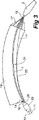
図3は本発明が解決しようとする問題点を示し、図4はこの問題点が本発明の一実施例によるトリガー・ワイヤ・ガイドの使用によりいかに解決されるかを示す。プロテーゼ留置装置は、図2に示すように留置段階において、胸部アーチのような患者の湾曲したルーメン内にあるようなより現実的な構造で示されている。 FIG. 3 illustrates the problem that the present invention seeks to solve, and FIG. 4 illustrates how this problem is solved by the use of a trigger wire guide according to one embodiment of the present invention. The prosthetic indwelling device is shown in a more realistic structure such as in the patient's curved lumen, such as a chest arch, during the indwelling stage as shown in FIG.
図3に示すように、本発明のトリガー・ワイヤ・ガイド7が無い場合には、トリガー・ワイヤ11は、ガイド・ワイヤ・カテーテル1とカテーテル・ボディ26との間のルーメンからプロテーゼ19用の近位係留ループ18まで伸びる。近位係留ループ18は、収納した状態にあるノーズコーン拡張器3に隣接する露出したステント17を保持する。トリガー・ワイヤ11は、ガイド・ワイヤ・カテーテル1の湾曲に沿って進まずに、直線状のラインに沿って進み、それによりプロテーゼ19の壁25と当たり、必要な場合に引き抜くことが困難となり、重篤な場合には、プロテーゼのステントと絡み合ってジャム状態になるかあるいは破損する。
As shown in FIG. 3, in the absence of the
上記の問題は、図4に示すように凹部24内にあるガイド・ワイヤ・カテーテル1の一部に沿って伸びるトリガー・ワイヤ・ガイド7を使用することにより解決される。この構成により、トリガー・ワイヤ11は、プロテーゼ19とは当たらない。
The above problem is solved by using a
図5−7にはプロテーゼ留置装置の一部が示され、それは留置装置の長さを延ばすようなガイド・ワイヤ・カテーテル1を含み、そしてガイド・ワイヤ・カテーテル1の近位端にはノーズコーン拡張器3がある。
FIGS. 5-7 show a portion of the prosthesis indwelling device, which includes a guide wire catheter 1 that extends the length of the indwelling device, and a nose cone at the proximal end of the guide wire catheter 1 There is a
トリガー・ワイヤ・ガイド7が、ノーズコーン拡張器3から後方に伸びてガイド・ワイヤ・カテーテル1を包囲している。トリガー・ワイヤ・ガイド7は、ガイド・ワイヤ・カテーテル1と同軸上にあり3個のルーメン9を有し、そこを介して使用中はトリガー・ワイヤ11が通過する。
A
ノーズコーン拡張器3の丁度先端には、トリガー・ワイヤ・ガイド7に開口13が形成されている。トリガー・ワイヤ11は、各ルーメン9内に入り、そこを出て、開口13内を伸びてループ15の状態にあり、その結果ループ15が、プロテーゼ19のジグザグ状態のステント17に係合する(図7)。トリガー・ワイヤ11は、ルーメン9に沿って進み、ノーズコーン拡張器3の領域内で終端する。ステント17を解放するのが好ましい場合には、トリガー・ワイヤ11は、図1,2で議論したように、引き抜かれる。
An
プロテーゼ19も図7に示されている。この実施例においては、プロテーゼ19の近位端のステント17は、カバーされた状態にあるステントであり、一方図2においてはカバーされていない近位端ステントが示されている。トリガー・ワイヤ11を用いて保持する原理はどちらも同一であるが、但し図7においては、ループ15状態にあるトリガー・ワイヤ11はグラフト材料も通過する。
A
ステントとグラフト材料に直接係合するループ15の使用例に対する別の実施例として、図8に示した構成が用いられる。図8においては、糸の一部(例えば、単繊維あるいは織った縫合材料)である係留ループ16を、トリガー・ワイヤ11とステント17とノット18を有するプロテーゼであるグラフト材料19の周囲でループと共に使用される。トリガー・ワイヤ11が引き抜かれると、ステント17とプロテーゼ19はトリガー・ワイヤ11から解放される。このような状況において、糸のループである係留ループ16は、ステント17あるいはプロテーゼ19に取り付けられた状態にある。
As another example for the use case of the
図9,10,11に示した実施例においては、この実施例の留置装置は、留置装置の長さ方向に沿って伸びるトリガー・ワイヤ・カテーテル50を有し、トリガー・ワイヤ・カテーテル50の近位端にはノーズ・コーン拡張器52がある。トリガー・ワイヤ・ガイド54が、ノーズ・コーン拡張器52から戻る方向に伸びて、トリガー・ワイヤ・カテーテル50の周囲に配置されている。トリガー・ワイヤ・ガイド54は、トリガー・ワイヤ・カテーテル50と同軸状態にあり、拡張部分56と細い管状部分58とを有する。管状部分58の領域には、トリガー・ワイヤ・カテーテル50と管状部分58との間に管状ルーメンがあり、そこをトリガー・ワイヤ11が通過する。
9, 10 and 11, the indwelling device of this embodiment has a
ノーズ・コーン拡張器52の近傍の拡張部分56においては、トリガー・ワイヤは、ルーメン60に連続する中央環状ルーメン62から伸びて、ループ66の形態で細長い開口64を通過し、更に中央環状ルーメン62内に入る。ループ66は、ステントあるいはプロテーゼのグラフト材料と係合して、プロテーゼの近位端が解放されるまで、収縮した状態に保持する。別の構成として、トリガー・ワイヤ11は、プロテーゼのステントに結びつけられた縫合糸に係合し、それが解放されるまで、収縮した状態に保持する。
In the
プロテーゼを解放するときは、トリガー・ワイヤ11が引き抜かれるが、これは図4,5で議論した通りである。
When releasing the prosthesis, the
留置装置のこの実施例においては、管状部分58は、留置カテーテル70のルーメン68内に伸びる。その結果ガイド・ワイヤのどの部分も、ステントグラフトあるいはプロテーゼが収納される留置装置内の領域にあって見ることが出来ない。
In this embodiment of the indwelling device, the
図12は、本発明の更なる実施例のトリガー・ワイヤ・ガイドを組み込んだ留置装置の詳細部分図であり、図13は図12に示した実施例の断面図である。 12 is a detailed partial view of an indwelling device incorporating a trigger wire guide of a further embodiment of the present invention, and FIG. 13 is a cross-sectional view of the embodiment shown in FIG.
この実施例においては、留置装置のガイド・ワイヤ・カテーテル80は、その長さの少なくとも一部に沿って、逆V字型断面要素81がハンダ付けされるかあるいは他の手段で固定される。この逆V字型断面要素81とガイド・ワイヤ・カテーテル80がそれらの間にルーメン84を形成する。この実施例の場合、ハンダ83を用いて逆V字型断面要素81をガイド・ワイヤ・カテーテルに固定している。トリガー・ワイヤ85は、ルーメン84に沿ってその中を通過し、逆V字型断面要素81が存在しない領域88内からループ86の状態で出る。ループ86は、プロテーゼのステントと係合して、それが解放されるときまで、ステントを保持するか、あるいはプロテーゼのステントに結びつけられた縫合糸に係合する。
In this embodiment, the indwelling device
図14は、本発明の更なる実施例のトリガー・ワイヤ・ガイドを組み込んだ留置装置の詳細部分図であり、図15は図14に示した実施例の断面図である。 FIG. 14 is a detailed partial view of an indwelling device incorporating a trigger wire guide of a further embodiment of the present invention, and FIG. 15 is a cross-sectional view of the embodiment shown in FIG.
この実施例において、留置装置のガイド・ワイヤ・カテーテル90は、ガイド・ワイヤ・カテーテル90の周囲に配置され、ガイド・ワイヤ・カテーテル90にポイント92とポイント93でクリンプされている同心金属チューブ91を有する。これによりガイド・ワイヤ・カテーテルと共にトリガー・ワイヤの通路用のルーメン94を形成する。この実施例においては、3本のトリガー・ワイヤが示されているが、1本のトリガー・ワイヤあるいは他の構成のトリガー・ワイヤも採用可能である。トリガー・ワイヤ96は、ルーメン96に沿って通過し、領域98でループ97の形態で出る。この領域98には、クリンプされたチューブである同心金属チューブ91内に切り抜き99が存在する、ループ97は、プロテーゼのステントと係合し、それが解放されるまで、ステントを保持するか、あるいはプロテーゼのステントに結びつけられた縫合糸に係合する。
In this embodiment, the indwelling device
本明細書を通して、様々な示唆が本発明の範囲について与えられているが、本発明は、これらの内の1つに限定されるものではなく、これらを組み合わせた複数のものにもある。ここに示した実施例は、単に例示のためで、本発明の範囲を制限するよう解釈してはならない。 Throughout this specification, various suggestions have been given for the scope of the present invention, but the present invention is not limited to one of these, and there are multiple combinations thereof. The examples given here are merely illustrative and should not be construed to limit the scope of the invention.
本明細書を通して、特に断りのない限り「有する」「含む」等の言葉は、それら以外のもの含まない、排除するよう解釈すべきではない。 Throughout this specification, unless stated otherwise, words such as “having” and “including” should not be construed as excluding or excluding others.
1 ガイド・ワイヤ・カテーテル
3 ノーズ・コーン拡張器
4 ポート
7 トリガー・ワイヤ・ガイド
11 トリガー・ワイヤ
13 開口
15 ループ
16 係留ループ
17 ステント
18 ノット/近位係留ループ
19 プロテーゼ
20 遠位端
22 近位端
26 カテーテル・ボディ
24 凹部
26 留置用カテーテル
28 シース
30 シース終端点
32 皮下シリンジ取り付け点
34 ピンバイス
36 サイドチューブ
40,41 摘みネジ
38、42 トリガー・ワイヤ解放機構
50 ガイド・ワイヤ・カテーテル
52 ノーズ・コーン拡張器
54 トリガー・ワイヤ・ガイド
56 拡大部分
58 管状部分
60 ルーメン
62 中央環状ルーメン
64 細長い開口
66 ループ
68 ルーメン
70 留置カテーテル
80 ガイド・ワイヤ・カテーテル
81 V字型断面要素
82 逆V字型断面要素
83 ハンダ
84 ルーメン
85 トリガー・ワイヤ
86 ループ
88 領域
90 ガイド・ワイヤ・カテーテル
91 同心金属チューブ
92,93 ポイント
94 ルーメン
96 トリガー・ワイヤ
97 ループ
98 領域
99 カットアウト
1
Claims (15)
(A)ノーズコーン拡張器(3)まで伸びるワイヤ・ガイド・カテーテル(1)と、
(B)前記プロテーゼ(19)の近位端を、前記ノーズコーン拡張器(3)の遠端に保持するトリガー・ワイヤ解放機構(38)と
(C)前記トリガー・ワイヤ解放機構(38)と前記ノーズコーン拡張器(3)の間を部分的に延びるトリガー・ワイヤ・ガイド(7)と、
を有し、
前記トリガー・ワイヤ・ガイド(7)は、
(C1)前記ノーズコーン拡張器(3)に隣接する拡張した近位部分と、
(C2)前記拡張した近位部分に隣接する管状本体部分であって、前記拡張した近位部分より小さくされている外径を有する管状本体部分と、
(C3)前記トリガー・ワイヤ・ガイド(7)の長さの少なくとも一部に沿ったダクトであって、前記トリガー・ワイヤ(11)用のルーメン(9)を有するダクトと、
(C4)前記ダクトに形成された開口(13)であって、前記ノーズコーン拡張器(3)に隣接し、前記トリガー・ワイヤ・ガイド(7)の拡張した近位部分に沿って形成されている開口(13)と、
を有し、
前記トリガー・ワイヤ(11)は、前記ダクトから出て前記プロテーゼ、プロテーゼのステント(17)、又はプロテーゼを保持する縫合糸に係合し、前記プロテーゼを保持する
ことを特徴とするプロテーゼ留置装置。In the prosthesis indwelling device for indwelling the prosthesis (19),
(A) a wire guide catheter (1) extending to the nose cone dilator (3);
(B) a trigger wire release mechanism (38) that holds the proximal end of the prosthesis (19) at the distal end of the nose cone dilator (3); (C) the trigger wire release mechanism (38); A trigger wire guide (7) partially extending between the nose cone dilator (3);
Have
The trigger wire guide (7)
(C1) an expanded proximal portion adjacent to the nose cone dilator (3);
(C2) and the a tubular body portion adjacent to the extended proximal portion, the tubular body portion having an outer diameter that is smaller than the proximal portion and the extension,
(C3) a duct along at least a portion of the length of the trigger wire guide (7), a duct which have a lumen (9) for said trigger wire (11),
(C4) wherein a duct opening formed (13), wherein adjacent the nose cone dilator (3), is formed along the extended proximal portion of the trigger wire guide (7) An opening (13),
Have
The trigger wire (11) engages with the prosthesis, the stent (17) of the prosthesis, or the suture that holds the prosthesis out of the duct, and holds the prosthesis.
ことを特徴とする請求項1記載のプロテーゼ留置装置。The prosthesis placement device according to claim 1, characterized in that the duct surrounds the wire guide catheter (1) coaxially.
ことを特徴とする請求項1記載のプロテーゼ留置装置。The prosthesis placement device according to claim 1, characterized in that the duct is formed of a coaxial tube (91) clamped around the wire guide catheter (90).
を有する構成要素(81)で形成される
ことを特徴とする請求項1記載のプロテーゼ留置装置。The prosthesis indwelling device according to claim 1, characterized in that the duct is formed of a component (81) having a V-shaped cross section held by the wire guide catheter (80).
(A)近位端に伸びるガイドワイヤカテーテル(1)と、
(B)前記プロテーゼ(19)の近位端を、前記ガイド・ワイヤ・カテーテル(1)近位端に保持するトリガー・ワイヤ解放機構(38)と
(C)トリガー・ワイヤ・ガイド(7)であって、
(C1)拡張した近位部分と、
(C2)前記拡張した近位部分に隣接する管状本体部分であって、外径が前記拡張した近位部分の外径より小さくされている管状本体部分と、
(C3)前記トリガー・ワイヤ・ガイド(7)の長さの少なくとも一部に沿ったダクトであって、前記トリガー・ワイヤ(11)用のルーメン(9)を有するダクトと、
(C4)前記ダクトに形成された開口(13)であって、前記ノーズコーン拡張器(3)に隣接し、前記トリガー・ワイヤ・ガイド(7)の拡張した近位部分に沿って形成されている開口と、
を有し、
前記トリガー・ワイヤ(11)は、前記ダクトから出て前記プロテーゼ、プロテーゼのステント(17)、又はプロテーゼを保持する縫合糸に係合し、前記プロテーゼを保持する
ことを特徴とするプロテーゼ留置装置。In a prosthesis indwelling device for indwelling a prosthesis,
(A) a guidewire catheter (1) extending to the proximal end;
(B) a proximal end of the prosthesis (19), with the guide wire catheter (1) trigger wire release mechanism to retain the proximal end (38) and (C) trigger wire guide (7) There,
(C1) an expanded proximal portion;
(C2) a tubular body portion adjacent to said expanded proximal portion, and a tubular body portion having an outer diameter being smaller than the outer diameter of the proximal portion which is the extended,
(C3) a duct along at least a portion of the length of the trigger wire guide (7), a duct which have a lumen (9) for said trigger wire (11),
(C4) wherein a duct opening formed (13), wherein adjacent the nose cone dilator (3), is formed along the extended proximal portion of the trigger wire guide (7) With an opening,
Have
The trigger wire (11) exits from the duct and engages the prosthesis, a prosthesis stent (17), or a suture that holds the prosthesis, and holds the prosthesis.
前記ダクトは、前記領域の少なくとも一部に渡って伸びる
ことを特徴とする請求項6記載のプロテーゼ留置装置。The prosthesis placement device has a region where the prosthesis is held,
The prosthesis placement device according to claim 6, wherein the duct extends over at least a part of the region.
ことを特徴とする請求項6記載のプロテーゼ留置装置。The prosthesis placement device according to claim 6, characterized in that the duct surrounds the wire guide catheter (1) coaxially.
ことを特徴とする請求項6記載のプロテーゼ留置装置。The prosthesis placement device according to claim 6, characterized in that the duct is formed of a coaxial tube (91) clamped around the wire guide catheter (90).
ことを特徴とする請求項6記載のプロテーゼ留置装置。The prosthesis indwelling device according to claim 6, characterized in that the duct is formed of a component (81) having a V-shaped cross section held by the wire guide catheter (80).
(A)近位端まで伸び、拡大領域を有する留置カテーテルと、
(B)前記プロテーゼ(19)の近位端を、前記留置カテーテルの近位端に保持するトリガー・ワイヤ・ガイド(7)であって、
(B1)ノーズコーン拡張器(3)に隣接する拡張した近位部分と、
(B2)前記拡張した近位部分に隣接する管状本体部分であって、外径が前記拡張した近位部分の外径より小さくされている管状本体部分と、
(B3)記トリガー・ワイヤ(11)用のルーメン(9)を有するダクトと、
(B4)前記ダクトに形成された開口(13)であって、前記トリガー・ワイヤ・ガイド(7)の拡張した近位部分に沿って形成されている開口と、
を有し、
前記トリガー・ワイヤ(11)は、前記ダクトから出て、前記プロテーゼを前記プロテーゼ留置装置を保持する
ことを特徴とするプロテーゼ留置装置。In the prosthesis indwelling device for indwelling the prosthesis (19),
(A) an indwelling catheter extending to the proximal end and having an enlarged region;
(B) a trigger wire guide (7) that holds the proximal end of the prosthesis (19) at the proximal end of the indwelling catheter;
(B1) an expanded proximal portion adjacent to the nose cone dilator (3);
(B2) a tubular body portion adjacent to said expanded proximal portion, and a tubular body portion having an outer diameter being smaller than the outer diameter of the proximal portion which is the extended,
(B3) A duct having a lumen (9) for the trigger wire (11);
(B4) wherein a duct opening formed (13), an opening is formed along a proximal portion that extends in the trigger wire guide (7),
Have
The trigger wire (11) exits from the duct and holds the prosthesis in place of the prosthesis placement device.
ことを特徴とする請求項12記載のプロテーゼ留置装置。13. Prosthesis placement device according to claim 12, characterized in that the trigger wire guide (7) has three lumens (9) for the trigger wire (11).
前記トリガー・ワイヤ・ガイド(7)は、前記ガイド・ワイヤ・カテーテルを同軸状に保持する
ことを特徴とする請求項12記載のプロテーゼ留置装置。The region has a guide wire catheter;
13. The prosthesis placement device according to claim 12, wherein the trigger wire guide (7) holds the guide wire catheter coaxially.
ことを特徴とする請求項14記載のプロテーゼ留置装置。The trigger wire guide (7) is formed coaxially with and clamped to the guide wire catheter.
The prosthesis indwelling device according to claim 14.
Applications Claiming Priority (5)
| Application Number | Priority Date | Filing Date | Title |
|---|---|---|---|
| US38405602P | 2002-05-29 | 2002-05-29 | |
| US60/384,056 | 2002-05-29 | ||
| US39268202P | 2002-06-28 | 2002-06-28 | |
| US60/392,682 | 2002-06-28 | ||
| PCT/US2003/016791 WO2003101518A1 (en) | 2002-05-29 | 2003-05-29 | Trigger wire system for a prosthesis deployment device |
Publications (2)
| Publication Number | Publication Date |
|---|---|
| JP2005535364A JP2005535364A (en) | 2005-11-24 |
| JP4575151B2 true JP4575151B2 (en) | 2010-11-04 |
Family
ID=29715306
Family Applications (1)
| Application Number | Title | Priority Date | Filing Date |
|---|---|---|---|
| JP2004508870A Expired - Lifetime JP4575151B2 (en) | 2002-05-29 | 2003-05-29 | Trigger wire system for prosthesis placement devices |
Country Status (9)
| Country | Link |
|---|---|
| US (2) | US7803177B2 (en) |
| EP (1) | EP1509271B1 (en) |
| JP (1) | JP4575151B2 (en) |
| AT (1) | ATE310559T1 (en) |
| AU (1) | AU2003273575B2 (en) |
| CA (1) | CA2486390C (en) |
| DE (1) | DE60302459T2 (en) |
| DK (1) | DK1509271T3 (en) |
| WO (1) | WO2003101518A1 (en) |
Families Citing this family (187)
| Publication number | Priority date | Publication date | Assignee | Title |
|---|---|---|---|---|
| US7491232B2 (en) | 1998-09-18 | 2009-02-17 | Aptus Endosystems, Inc. | Catheter-based fastener implantation apparatus and methods with implantation force resolution |
| US20050177180A1 (en) | 2001-11-28 | 2005-08-11 | Aptus Endosystems, Inc. | Devices, systems, and methods for supporting tissue and/or structures within a hollow body organ |
| US20070073389A1 (en) | 2001-11-28 | 2007-03-29 | Aptus Endosystems, Inc. | Endovascular aneurysm devices, systems, and methods |
| US8231639B2 (en) | 2001-11-28 | 2012-07-31 | Aptus Endosystems, Inc. | Systems and methods for attaching a prosthesis within a body lumen or hollow organ |
| CA2464048C (en) | 2001-11-28 | 2010-06-15 | Lee Bolduc | Endovascular aneurysm repair system |
| US9320503B2 (en) | 2001-11-28 | 2016-04-26 | Medtronic Vascular, Inc. | Devices, system, and methods for guiding an operative tool into an interior body region |
| US7147657B2 (en) * | 2003-10-23 | 2006-12-12 | Aptus Endosystems, Inc. | Prosthesis delivery systems and methods |
| CA2489495C (en) | 2002-06-28 | 2010-07-13 | Cook Incorporated | Thoracic aortic aneurysm stent graft |
| AU2003258337A1 (en) | 2002-08-23 | 2004-03-11 | Cook Incorporated | Asymmetric stent graft attachment |
| CA2496136C (en) * | 2002-08-23 | 2010-05-04 | William A. Cook Australia Pty. Ltd. | Composite prosthesis |
| US7678068B2 (en) | 2002-12-02 | 2010-03-16 | Gi Dynamics, Inc. | Atraumatic delivery devices |
| US7025791B2 (en) | 2002-12-02 | 2006-04-11 | Gi Dynamics, Inc. | Bariatric sleeve |
| US7695446B2 (en) | 2002-12-02 | 2010-04-13 | Gi Dynamics, Inc. | Methods of treatment using a bariatric sleeve |
| US7608114B2 (en) | 2002-12-02 | 2009-10-27 | Gi Dynamics, Inc. | Bariatric sleeve |
| CA2512203C (en) | 2002-12-02 | 2012-10-23 | Gi Dynamics, Inc. | Bariatric sleeve |
| US7611528B2 (en) * | 2003-01-24 | 2009-11-03 | Medtronic Vascular, Inc. | Stent-graft delivery system |
| US7763063B2 (en) | 2003-09-03 | 2010-07-27 | Bolton Medical, Inc. | Self-aligning stent graft delivery system, kit, and method |
| US11259945B2 (en) | 2003-09-03 | 2022-03-01 | Bolton Medical, Inc. | Dual capture device for stent graft delivery system and method for capturing a stent graft |
| US8500792B2 (en) | 2003-09-03 | 2013-08-06 | Bolton Medical, Inc. | Dual capture device for stent graft delivery system and method for capturing a stent graft |
| US11596537B2 (en) | 2003-09-03 | 2023-03-07 | Bolton Medical, Inc. | Delivery system and method for self-centering a proximal end of a stent graft |
| US20070198078A1 (en) | 2003-09-03 | 2007-08-23 | Bolton Medical, Inc. | Delivery system and method for self-centering a Proximal end of a stent graft |
| US9198786B2 (en) | 2003-09-03 | 2015-12-01 | Bolton Medical, Inc. | Lumen repair device with capture structure |
| US8292943B2 (en) | 2003-09-03 | 2012-10-23 | Bolton Medical, Inc. | Stent graft with longitudinal support member |
| US20080264102A1 (en) | 2004-02-23 | 2008-10-30 | Bolton Medical, Inc. | Sheath Capture Device for Stent Graft Delivery System and Method for Operating Same |
| US7651519B2 (en) * | 2003-09-16 | 2010-01-26 | Cook Incorporated | Prosthesis deployment system |
| US8043357B2 (en) | 2003-10-10 | 2011-10-25 | Cook Medical Technologies Llc | Ring stent |
| US7413573B2 (en) | 2003-10-10 | 2008-08-19 | William A. Cook Australia Pty. Ltd. | Fenestrated stent grafts |
| US7998186B2 (en) | 2003-10-14 | 2011-08-16 | William A. Cook Australia Pty. Ltd. | Introducer for a side branch device |
| EP3050542B1 (en) | 2003-10-14 | 2022-03-16 | Cook Medical Technologies LLC | Introducer for an iliac side branch device |
| DE602004026756D1 (en) * | 2003-10-15 | 2010-06-02 | Cook Inc | HOLDING DEVICE FOR A PROSTHESIS SYSTEM |
| EP3424463A1 (en) * | 2003-11-08 | 2019-01-09 | Cook Medical Technologies LLC | Aorta and branch vessel stent grafts and system |
| EP1708655A1 (en) | 2003-12-09 | 2006-10-11 | GI Dynamics, Inc. | Apparatus to be anchored within the gastrointestinal tract and anchoring method |
| US8057420B2 (en) | 2003-12-09 | 2011-11-15 | Gi Dynamics, Inc. | Gastrointestinal implant with drawstring |
| US9498322B2 (en) * | 2004-03-31 | 2016-11-22 | Cook Medical Technologies Llc | Multi-portion endoluminal prosthesis |
| US8048140B2 (en) | 2004-03-31 | 2011-11-01 | Cook Medical Technologies Llc | Fenestrated intraluminal stent system |
| CA2561188A1 (en) * | 2004-03-31 | 2005-10-20 | Med Institute, Inc. | Endoluminal graft with a prosthetic valve |
| EP1729684B1 (en) * | 2004-03-31 | 2010-12-15 | Cook Incorporated | Stent deployment device |
| US8465536B2 (en) * | 2004-04-06 | 2013-06-18 | Cook Medical Technologies Llc | Prosthesis deployment system |
| WO2006007389A1 (en) * | 2004-06-16 | 2006-01-19 | Cook Incorprated | Thoracic deployment device and stent graft |
| ATE506042T1 (en) | 2004-07-09 | 2011-05-15 | Gi Dynamics Inc | DEVICES FOR PLACEMENT OF A GASTROINTESTINAL SLEEVE |
| EP3195829A1 (en) | 2004-09-17 | 2017-07-26 | GI Dynamics, Inc. | Gastrointestinal achor |
| CA2581857C (en) | 2004-09-28 | 2013-07-16 | William A. Cook Australia Pty. Ltd. | Device for treating aortic dissection |
| JP2006116184A (en) * | 2004-10-25 | 2006-05-11 | Piolax Medical Device:Kk | Stent inserting device |
| US7914569B2 (en) | 2005-05-13 | 2011-03-29 | Medtronics Corevalve Llc | Heart valve prosthesis and methods of manufacture and use |
| US7976488B2 (en) | 2005-06-08 | 2011-07-12 | Gi Dynamics, Inc. | Gastrointestinal anchor compliance |
| JP4627687B2 (en) * | 2005-06-20 | 2011-02-09 | Junken Medical株式会社 | Stent insertion device |
| US8118852B2 (en) * | 2005-07-13 | 2012-02-21 | Cook Medical Technologies Llc | Introducer for self-expandable medical device |
| WO2007014088A2 (en) * | 2005-07-25 | 2007-02-01 | Cook Incorporated | Intraluminal prosthesis and stent |
| CN101466316B (en) | 2005-10-20 | 2012-06-27 | 阿普特斯内系统公司 | Devices systems and methods for prosthesis delivery and implantation including the use of a fastener tool |
| WO2007054014A1 (en) * | 2005-11-09 | 2007-05-18 | Ning Wen | Delivery device for delivering a self-expanding stent |
| US8709060B2 (en) * | 2005-12-23 | 2014-04-29 | Cook Medical Technologies Llc | Prosthesis deployment system |
| US20070156223A1 (en) * | 2005-12-30 | 2007-07-05 | Dennis Vaughan | Stent delivery system with improved delivery force distribution |
| WO2007100716A2 (en) * | 2006-02-27 | 2007-09-07 | William A. Cook Australia Pty. Ltd. | Retention of stents |
| US8147541B2 (en) * | 2006-02-27 | 2012-04-03 | Aortx, Inc. | Methods and devices for delivery of prosthetic heart valves and other prosthetics |
| US9757260B2 (en) * | 2006-03-30 | 2017-09-12 | Medtronic Vascular, Inc. | Prosthesis with guide lumen |
| US20070244547A1 (en) * | 2006-04-18 | 2007-10-18 | Medtronic Vascular, Inc., A Delaware Corporation | Device and Method for Controlling the Positioning of a Stent Graft Fenestration |
| US9308105B2 (en) * | 2006-04-19 | 2016-04-12 | Cook Medical Technologies Llc | Delivery device for an endoluminal prosthesis |
| US8828074B2 (en) * | 2006-04-21 | 2014-09-09 | Medtronic Vascular, Inc. | Stent graft having short tube graft for branch vessel |
| EP2015706B1 (en) | 2006-04-27 | 2016-08-03 | Cook Medical Technologies LLC | Deploying medical implants |
| WO2007142962A2 (en) | 2006-06-02 | 2007-12-13 | William A. Cook Australia Pty. Ltd. | Multi-port delivery device |
| WO2008015257A2 (en) * | 2006-08-02 | 2008-02-07 | Syntach Ag | Luminal implant with large expansion ratio |
| US8801647B2 (en) | 2007-02-22 | 2014-08-12 | Gi Dynamics, Inc. | Use of a gastrointestinal sleeve to treat bariatric surgery fistulas and leaks |
| AU2008251804B2 (en) | 2007-05-11 | 2013-01-10 | Cook Incorporated | Stent grafts for the thoracic aorta |
| US8092510B2 (en) * | 2007-07-25 | 2012-01-10 | Cook Medical Technologies Llc | Retention wire for self-expanding stent |
| WO2009023221A1 (en) | 2007-08-13 | 2009-02-19 | William A. Cook Australia Pty. Ltd. | Deployment device |
| US20100174354A1 (en) * | 2007-09-01 | 2010-07-08 | Sapporo Medical University | Stent placement device and stent placement method |
| US9107741B2 (en) * | 2007-11-01 | 2015-08-18 | Cook Medical Technologies Llc | Flexible stent graft |
| US7566342B2 (en) * | 2007-12-27 | 2009-07-28 | Cook Incorporated | Delivery system for medical device |
| US8157853B2 (en) * | 2008-01-24 | 2012-04-17 | Medtronic, Inc. | Delivery systems and methods of implantation for prosthetic heart valves |
| US9393115B2 (en) | 2008-01-24 | 2016-07-19 | Medtronic, Inc. | Delivery systems and methods of implantation for prosthetic heart valves |
| MX2010008171A (en) | 2008-01-24 | 2010-12-07 | Medtronic Inc | Stents for prosthetic heart valves. |
| US9149358B2 (en) * | 2008-01-24 | 2015-10-06 | Medtronic, Inc. | Delivery systems for prosthetic heart valves |
| CA2727000C (en) | 2008-06-04 | 2014-01-07 | Gore Enterprise Holdings, Inc. | Controlled deployable medical device and method of making the same |
| AU2009255613B2 (en) | 2008-06-04 | 2013-09-19 | W. L. Gore & Associates, Inc. | Controlled deployable medical device and method of making the same |
| ES2638293T3 (en) | 2008-06-30 | 2017-10-19 | Bolton Medical Inc. | Abdominal aortic aneurysm systems |
| EP2317958B1 (en) * | 2008-08-26 | 2012-02-29 | William A. Cook Australia Pty. Ltd. | Thoracic introducer |
| CA2740867C (en) | 2008-10-16 | 2018-06-12 | Aptus Endosystems, Inc. | Devices, systems, and methods for endovascular staple and/or prosthesis delivery and implantation |
| US11376114B2 (en) | 2008-10-31 | 2022-07-05 | Cook Medical Technologies Llc | Introducer for deploying a stent graft in a curved lumen and stent graft therefor |
| GB2464977B (en) | 2008-10-31 | 2010-11-03 | William Cook Europe As | Introducer for deploying a stent graft in a curved lumen and stent graft therefor |
| US8886636B2 (en) * | 2008-12-23 | 2014-11-11 | Yahoo! Inc. | Context transfer in search advertising |
| AU2009200350B1 (en) * | 2009-02-02 | 2009-07-16 | Cook Incorporated | Preloaded stent graft delivery device |
| US9101506B2 (en) * | 2009-03-13 | 2015-08-11 | Bolton Medical, Inc. | System and method for deploying an endoluminal prosthesis at a surgical site |
| KR101828088B1 (en) * | 2009-04-15 | 2018-02-09 | 마이크로벤션, 인코포레이티드 | Implant delivery system |
| US8961539B2 (en) * | 2009-05-04 | 2015-02-24 | Boston Scientific Scimed, Inc. | Endoscopic implant system and method |
| CA2766347C (en) | 2009-06-23 | 2017-04-25 | Endospan Ltd. | Vascular prostheses for treating aneurysms |
| GB2474252B (en) | 2009-10-07 | 2012-01-25 | Cook Medical Technologies Llc | Deployment handle for an introducer |
| JP5651183B2 (en) | 2009-10-13 | 2015-01-07 | クック メディカル テクノロジーズ エルエルシーCook Medical Technologies Llc | Paraplegia preventive stent graft |
| US9095456B2 (en) | 2009-10-13 | 2015-08-04 | Cook Medical Technologies Llc | Paraplegia prevention stent graft |
| EP2490629B1 (en) | 2009-10-20 | 2019-05-22 | Cook Medical Technologies, LLC | Rotational controlled deployment device |
| JP5880869B2 (en) * | 2009-10-29 | 2016-03-09 | クック・メディカル・テクノロジーズ・リミテッド・ライアビリティ・カンパニーCook Medical Technologies Llc | Stent delivery system with Nitinol trigger wire |
| DE102009055969A1 (en) * | 2009-11-27 | 2011-06-01 | Transcatheter Technologies Gmbh | Device and set for folding or unfolding a medical implant and method |
| WO2011084342A1 (en) | 2009-12-17 | 2011-07-14 | Cook Medical Technologies Llc | Delivery system with retractable proximal end |
| US8986363B2 (en) | 2009-12-30 | 2015-03-24 | Cook Medical Technologies Llc | Proximal release delivery system |
| CA2788328C (en) * | 2010-01-29 | 2015-12-08 | Cook Medical Technologies Llc | Mechanically expandable delivery and dilation systems |
| US8663305B2 (en) | 2010-04-20 | 2014-03-04 | Medtronic Vascular, Inc. | Retraction mechanism and method for graft cover retraction |
| US8623064B2 (en) | 2010-04-30 | 2014-01-07 | Medtronic Vascular, Inc. | Stent graft delivery system and method of use |
| US8747448B2 (en) | 2010-04-30 | 2014-06-10 | Medtronic Vascular, Inc. | Stent graft delivery system |
| US9526648B2 (en) | 2010-06-13 | 2016-12-27 | Synerz Medical, Inc. | Intragastric device for treating obesity |
| US10010439B2 (en) | 2010-06-13 | 2018-07-03 | Synerz Medical, Inc. | Intragastric device for treating obesity |
| US8628554B2 (en) | 2010-06-13 | 2014-01-14 | Virender K. Sharma | Intragastric device for treating obesity |
| US10420665B2 (en) | 2010-06-13 | 2019-09-24 | W. L. Gore & Associates, Inc. | Intragastric device for treating obesity |
| US9247942B2 (en) | 2010-06-29 | 2016-02-02 | Artventive Medical Group, Inc. | Reversible tubal contraceptive device |
| EP2588042A4 (en) | 2010-06-29 | 2015-03-18 | Artventive Medical Group Inc | Reducing flow through a tubular structure |
| US9149277B2 (en) | 2010-10-18 | 2015-10-06 | Artventive Medical Group, Inc. | Expandable device delivery |
| WO2012058582A1 (en) | 2010-10-29 | 2012-05-03 | Cook Medical Technologies Llc | Medical device delivery system and deployment method |
| US9095466B2 (en) * | 2010-11-16 | 2015-08-04 | W. L. Gore & Associates, Inc. | Apposition fiber for use in endoluminal deployment of expandable devices in tortuous anatomies |
| AU2010254599B1 (en) | 2010-12-15 | 2011-02-17 | Cook Incorporated | Hybrid Type A dissection device |
| CA2826022A1 (en) | 2011-02-03 | 2012-08-09 | Endospan Ltd. | Implantable medical devices constructed of shape memory material |
| GB2488986B (en) * | 2011-03-08 | 2013-07-10 | Cook Medical Technologies Llc | Introducer assembly and carrier element for a medical device |
| US10201336B2 (en) * | 2011-03-25 | 2019-02-12 | St. Jude Medical, Cardiology Division, Inc. | Device and method for delivering a vascular device |
| EP3053545B1 (en) | 2011-04-28 | 2019-09-18 | Cook Medical Technologies LLC | Apparatus for facilitating deployment of an endoluminal prosthesis |
| AU2011202175B1 (en) | 2011-05-11 | 2011-07-28 | Cook Medical Technologies Llc | Rotation operated delivery device |
| AU2011202174B1 (en) | 2011-05-11 | 2011-08-25 | Cook Medical Technologies Llc | Introducer with ratchet handle drive |
| JP4913251B1 (en) * | 2011-05-24 | 2012-04-11 | 株式会社カテックス | Stent delivery system |
| GB201109305D0 (en) | 2011-06-03 | 2011-07-20 | Vascutek Ltd | Method and apparatus for controlling the deployment of a stent |
| EP2535025A1 (en) | 2011-06-17 | 2012-12-19 | Cook Medical Technologies LLC | Trigger wire release mechanism |
| US8734500B2 (en) * | 2011-09-27 | 2014-05-27 | DePuy Synthes Products, LLC | Distal detachment mechanisms for vascular devices |
| CN102462565B (en) * | 2011-10-25 | 2014-03-26 | 张石江 | Recyclable and adjustable interventional stent for constricting blood vessels |
| US9017393B2 (en) * | 2011-10-31 | 2015-04-28 | Cook Medical Technologies Llc | Releasable top cap assembly |
| US8728148B2 (en) | 2011-11-09 | 2014-05-20 | Cook Medical Technologies Llc | Diameter reducing tie arrangement for endoluminal prosthesis |
| US9782282B2 (en) | 2011-11-14 | 2017-10-10 | W. L. Gore & Associates, Inc. | External steerable fiber for use in endoluminal deployment of expandable devices |
| US9877858B2 (en) | 2011-11-14 | 2018-01-30 | W. L. Gore & Associates, Inc. | External steerable fiber for use in endoluminal deployment of expandable devices |
| CN102488576B (en) * | 2011-11-25 | 2014-07-16 | 北京华脉泰科医疗器械有限公司 | Convey and release device for covered stents |
| EP2604232B1 (en) | 2011-12-14 | 2021-02-24 | Cook Medical Technologies LLC | Circumferential trigger wire for deploying an endoluminal prosthesis |
| AU2012200735C1 (en) | 2012-02-08 | 2013-01-24 | Cook Medical Technologies Llc | Orientation markers for endovascular delivery system |
| US9375308B2 (en) * | 2012-03-13 | 2016-06-28 | W. L. Gore & Associates, Inc. | External steerable fiber for use in endoluminal deployment of expandable devices |
| WO2013154749A1 (en) | 2012-04-12 | 2013-10-17 | Bolton Medical, Inc. | Vascular prosthetic delivery device and method of use |
| US8882828B2 (en) * | 2012-04-27 | 2014-11-11 | Medtronic Vascular, Inc. | Ring on a closed web stent-graft for use in tip capture |
| US9308107B2 (en) | 2012-08-27 | 2016-04-12 | Cook Medical Technologies Llc | Endoluminal prosthesis and delivery device |
| KR101296604B1 (en) * | 2012-09-05 | 2013-08-14 | 부산대학교 산학협력단 | Sheath and cerclage thread for mitral cerclage annuloplasty |
| US9750626B2 (en) * | 2012-10-31 | 2017-09-05 | Cook Medical Technologies Llc | Apparatus and methods for improved stent deployment |
| US9622893B2 (en) | 2012-12-20 | 2017-04-18 | Cook Medical Technologies Llc | Apparatus and method for improved deployment of endovascular grafts |
| US10350096B2 (en) | 2012-12-26 | 2019-07-16 | Cook Medical Technologies Llc | Expandable stent-graft system having diameter reducing connectors |
| EP2938291B2 (en) * | 2012-12-27 | 2023-01-11 | Venus MedTech (HangZhou), Inc. | Apparatus and set for folding or unfolding a medical implant comprising a clamping mechanism |
| CN105007860B (en) * | 2013-01-08 | 2017-05-10 | 恩多斯潘有限公司 | Minimization of stent graft migration during implantation |
| US8984733B2 (en) | 2013-02-05 | 2015-03-24 | Artventive Medical Group, Inc. | Bodily lumen occlusion |
| US9095344B2 (en) | 2013-02-05 | 2015-08-04 | Artventive Medical Group, Inc. | Methods and apparatuses for blood vessel occlusion |
| US9095463B2 (en) * | 2013-02-21 | 2015-08-04 | Medtronic Vascular, Inc. | Stent-graft delivery having a tip capture mechanism with elongated cables for gradual deployment and repositioning |
| CN105208969B (en) | 2013-03-11 | 2017-10-20 | 恩多斯潘有限公司 | Multicomponent stent-graft system for aortic dissection |
| US9545324B2 (en) | 2013-03-13 | 2017-01-17 | Cook Medical Technologies Llc | Pre-loaded iliac branch device and methods of deployment |
| EP3058901B1 (en) | 2013-03-15 | 2018-08-01 | Cook Medical Technologies LLC | Implant introducer with helical trigger wire |
| US9439751B2 (en) | 2013-03-15 | 2016-09-13 | Bolton Medical, Inc. | Hemostasis valve and delivery systems |
| EP2995283B1 (en) * | 2013-05-10 | 2019-09-18 | Olympus Corporation | Stent delivery system |
| PL2997992T3 (en) * | 2013-05-13 | 2022-03-21 | Inside Medical Indústria E Comércio De Produtos Médicos Hospitalares Ltda - Me | Mechanism for guiding and/or releasing an endoprosthesis at a blood vessel lesion region, used in a medical device of the type of a cathether |
| US10149968B2 (en) | 2013-06-14 | 2018-12-11 | Artventive Medical Group, Inc. | Catheter-assisted tumor treatment |
| US9636116B2 (en) | 2013-06-14 | 2017-05-02 | Artventive Medical Group, Inc. | Implantable luminal devices |
| US9737306B2 (en) | 2013-06-14 | 2017-08-22 | Artventive Medical Group, Inc. | Implantable luminal devices |
| US9737308B2 (en) | 2013-06-14 | 2017-08-22 | Artventive Medical Group, Inc. | Catheter-assisted tumor treatment |
| AU2013206712B1 (en) | 2013-07-03 | 2013-11-28 | Cook Medical Technologies Llc | Endovascular graft having a cannulation pocket |
| US10603197B2 (en) | 2013-11-19 | 2020-03-31 | Endospan Ltd. | Stent system with radial-expansion locking |
| EP2907485B1 (en) | 2014-02-16 | 2020-01-08 | Cook Medical Technologies LLC | Prosthesis delivery system |
| US10363043B2 (en) | 2014-05-01 | 2019-07-30 | Artventive Medical Group, Inc. | Treatment of incompetent vessels |
| US10959826B2 (en) | 2014-10-16 | 2021-03-30 | Cook Medical Technology LLC | Support structure for scalloped grafts |
| CN104546242B (en) * | 2014-12-02 | 2017-01-25 | 先健科技(深圳)有限公司 | Delivery devices for implants and implanted medical devices |
| WO2016098113A1 (en) | 2014-12-18 | 2016-06-23 | Endospan Ltd. | Endovascular stent-graft with fatigue-resistant lateral tube |
| EP3040056B1 (en) | 2014-12-29 | 2019-09-11 | Cook Medical Technologies LLC | Prosthesis deployment system |
| CA3007346C (en) * | 2015-01-11 | 2020-08-18 | Ascyrus Medical, Llc | Hybrid device for surgical aortic repair and method of using the same |
| WO2016168176A1 (en) | 2015-04-13 | 2016-10-20 | Cook Medical Technologies Llc | Axial lock and release stent deployment system |
| US10925762B2 (en) | 2015-09-01 | 2021-02-23 | Cook Medical Technologies Llc | Threaded modular handle for a prosthesis delivery device |
| US10610393B2 (en) | 2016-03-24 | 2020-04-07 | Cook Medical Technologies Llc | Wire retention and release mechanisms |
| US10813644B2 (en) | 2016-04-01 | 2020-10-27 | Artventive Medical Group, Inc. | Occlusive implant and delivery system |
| US10779980B2 (en) | 2016-04-27 | 2020-09-22 | Synerz Medical, Inc. | Intragastric device for treating obesity |
| US20180014957A1 (en) * | 2016-07-13 | 2018-01-18 | Boston Scientific Scimed, Inc. | Stent reconstrainment system for minimal volume in low profile delivery system |
| US10433991B2 (en) | 2016-07-18 | 2019-10-08 | Cook Medical Technologies Llc | Controlled expansion stent graft delivery system |
| US11135077B2 (en) | 2016-12-16 | 2021-10-05 | Cook Medical Technologies Llc | Method of air reduction in stent graft delivery device |
| ES2952776T3 (en) * | 2017-02-14 | 2023-11-06 | Gore & Ass | Implantable medical device placement systems |
| EP3932373B1 (en) | 2017-02-24 | 2022-12-21 | Bolton Medical, Inc. | Delivery system for radially constricting a stent graft |
| ES2863978T3 (en) | 2017-02-24 | 2021-10-13 | Bolton Medical Inc | System for radially constricting a stent graft |
| EP3534838B1 (en) | 2017-02-24 | 2021-01-27 | Bolton Medical, Inc. | Radially adjustable stent graft delivery system |
| CA3055567C (en) | 2017-03-08 | 2021-11-23 | W. L. Gore & Associates, Inc. | Steering wire attach for angulation |
| US10709541B2 (en) | 2017-04-28 | 2020-07-14 | Cook Medical Technologies Llc | Systems and methods for adjusting the diameter of an endoluminal prosthesis and an endoluminal prosthesis configured for the same |
| US11096810B2 (en) | 2017-11-29 | 2021-08-24 | Cook Medical Technologies Llc | Preloaded pusher tip for endografts |
| US10641427B2 (en) | 2018-04-03 | 2020-05-05 | Mueller International, Llc | Stents and methods for repairing pipes |
| AU2019306239B2 (en) * | 2018-07-18 | 2022-08-25 | W. L. Gore & Associates, Inc. | Implantable medical device deployment system |
| CA3108510C (en) | 2018-08-31 | 2023-06-20 | W. L. Gore & Associates, Inc. | Pivot delivery system for implantable medical device |
| WO2020046364A1 (en) | 2018-08-31 | 2020-03-05 | W. L. Gore & Associates, Inc. | Apparatus, system, and method for steering an implantable medical device |
| US12114863B2 (en) | 2018-12-05 | 2024-10-15 | Microvention, Inc. | Implant delivery system |
| US11353154B2 (en) | 2019-02-19 | 2022-06-07 | Mueller International, Llc | Stent springs and stents for repairing pipes |
| US11187366B2 (en) | 2019-03-15 | 2021-11-30 | Mueller International, Llc | Stent for repairing a pipe |
| JP7329043B2 (en) * | 2019-03-29 | 2023-08-17 | 株式会社カネカ | Medical tubular body conveying device |
| US11326731B2 (en) * | 2019-04-24 | 2022-05-10 | Mueller International, Llc | Pipe repair assembly |
| US11391405B2 (en) | 2019-08-09 | 2022-07-19 | Mueller International, Llc | Deployment probe for pipe repair device |
| US11802646B2 (en) | 2019-08-09 | 2023-10-31 | Mueller International, Llc | Pipe repair device |
| US20210154036A1 (en) * | 2019-11-22 | 2021-05-27 | Cook Medical Technologies Llc | Stent graft trigger with indirect fixation |
| EP4171449A1 (en) | 2020-06-24 | 2023-05-03 | Bolton Medical, Inc. | Anti-backspin component for vascular prosthesis delivery device |
| GB2605559B (en) | 2021-01-07 | 2023-04-05 | Cook Medical Technologies Llc | Stent graft |
| CN119104000B (en) * | 2024-10-09 | 2025-12-12 | 德维嘉汽车电子系统(无锡)有限公司 | A concentric wire harness and a concentricity detection system for the concentric wire harness. |
Family Cites Families (20)
| Publication number | Priority date | Publication date | Assignee | Title |
|---|---|---|---|---|
| US5693083A (en) * | 1983-12-09 | 1997-12-02 | Endovascular Technologies, Inc. | Thoracic graft and delivery catheter |
| US4913141A (en) * | 1988-10-25 | 1990-04-03 | Cordis Corporation | Apparatus and method for placement of a stent within a subject vessel |
| DE3903380A1 (en) * | 1989-02-04 | 1990-08-09 | Frankenthal Ag Albert | FOLDING APPARATUS WITH SMOOTH CUTTING DEVICE |
| US5389087A (en) * | 1991-09-19 | 1995-02-14 | Baxter International Inc. | Fully exchangeable over-the-wire catheter with rip seam and gated side port |
| US5693084A (en) * | 1991-10-25 | 1997-12-02 | Cook Incorporated | Expandable transluminal graft prosthesis for repair of aneurysm |
| US5405378A (en) * | 1992-05-20 | 1995-04-11 | Strecker; Ernst P. | Device with a prosthesis implantable in the body of a patient |
| US5772668A (en) * | 1992-06-18 | 1998-06-30 | American Biomed, Inc. | Apparatus for placing an endoprosthesis |
| US5480423A (en) * | 1993-05-20 | 1996-01-02 | Boston Scientific Corporation | Prosthesis delivery |
| US5464449A (en) * | 1993-07-08 | 1995-11-07 | Thomas J. Fogarty | Internal graft prosthesis and delivery system |
| AU700717B2 (en) * | 1994-10-20 | 1999-01-14 | Intra Therapeutics, Inc. | Cystoscope delivery system |
| US5556414A (en) * | 1995-03-08 | 1996-09-17 | Wayne State University | Composite intraluminal graft |
| WO1996036297A1 (en) | 1995-05-19 | 1996-11-21 | Kanji Inoue | Transplantation instrument, method of bending same and method of transplanting same |
| US5830229A (en) * | 1997-03-07 | 1998-11-03 | Micro Therapeutics Inc. | Hoop stent |
| US5779732A (en) * | 1997-03-31 | 1998-07-14 | Medtronic, Inc. | Method and apparatus for implanting a film with an exandable stent |
| AUPO700897A0 (en) * | 1997-05-26 | 1997-06-19 | William A Cook Australia Pty Ltd | A method and means of deploying a graft |
| US5921952A (en) * | 1997-08-14 | 1999-07-13 | Boston Scientific Corporation | Drainage catheter delivery system |
| AUPP083597A0 (en) * | 1997-12-10 | 1998-01-08 | William A Cook Australia Pty Ltd | Endoluminal aortic stents |
| DE60035791T2 (en) * | 1999-11-11 | 2008-04-30 | Angiomed Gmbh & Co. Medizintechnik Kg | INTRODUCING DEVICE FOR AN IMPLANT |
| WO2002000288A1 (en) * | 2000-06-26 | 2002-01-03 | Kanji Inoue | Transporting device for transplanting instrument |
| US6641606B2 (en) | 2001-12-20 | 2003-11-04 | Cleveland Clinic Foundation | Delivery system and method for deploying an endovascular prosthesis |
-
2003
- 2003-05-29 DE DE60302459T patent/DE60302459T2/en not_active Expired - Lifetime
- 2003-05-29 DK DK03741824T patent/DK1509271T3/en active
- 2003-05-29 AU AU2003273575A patent/AU2003273575B2/en not_active Expired
- 2003-05-29 WO PCT/US2003/016791 patent/WO2003101518A1/en not_active Ceased
- 2003-05-29 JP JP2004508870A patent/JP4575151B2/en not_active Expired - Lifetime
- 2003-05-29 CA CA2486390A patent/CA2486390C/en not_active Expired - Lifetime
- 2003-05-29 EP EP03741824A patent/EP1509271B1/en not_active Expired - Lifetime
- 2003-05-29 US US10/447,406 patent/US7803177B2/en not_active Expired - Lifetime
- 2003-05-29 AT AT03741824T patent/ATE310559T1/en not_active IP Right Cessation
-
2010
- 2010-03-11 US US12/722,214 patent/US8114145B2/en not_active Expired - Fee Related
Also Published As
| Publication number | Publication date |
|---|---|
| AU2003273575B2 (en) | 2007-12-06 |
| WO2003101518A1 (en) | 2003-12-11 |
| DE60302459D1 (en) | 2005-12-29 |
| ATE310559T1 (en) | 2005-12-15 |
| US8114145B2 (en) | 2012-02-14 |
| AU2003273575A1 (en) | 2003-12-19 |
| US20100168838A1 (en) | 2010-07-01 |
| DK1509271T3 (en) | 2006-03-13 |
| DE60302459T2 (en) | 2006-08-03 |
| US7803177B2 (en) | 2010-09-28 |
| CA2486390A1 (en) | 2003-12-11 |
| CA2486390C (en) | 2011-01-04 |
| US20030233140A1 (en) | 2003-12-18 |
| JP2005535364A (en) | 2005-11-24 |
| EP1509271A1 (en) | 2005-03-02 |
| EP1509271B1 (en) | 2005-11-23 |
Similar Documents
| Publication | Publication Date | Title |
|---|---|---|
| JP4575151B2 (en) | Trigger wire system for prosthesis placement devices | |
| US7611529B2 (en) | Thoracic introducer | |
| JP5470399B2 (en) | Introducer for deploying a stent-graft in a curved lumen and stent graft therefor | |
| US7666219B2 (en) | Prosthesis deployment system retention device | |
| US9237960B2 (en) | Apparatus for curving an implantable medical device in a lumen | |
| US9889028B2 (en) | Implant release mechanism | |
| US10188538B2 (en) | Hybrid trigger wire for endografts | |
| US7854758B2 (en) | Exclusion of ascending/descending aorta and/or aortic arch aneurysm | |
| EP2387379B1 (en) | Stent graft and introducer assembly | |
| US11376114B2 (en) | Introducer for deploying a stent graft in a curved lumen and stent graft therefor |
Legal Events
| Date | Code | Title | Description |
|---|---|---|---|
| A621 | Written request for application examination |
Free format text: JAPANESE INTERMEDIATE CODE: A621 Effective date: 20060515 |
|
| A131 | Notification of reasons for refusal |
Free format text: JAPANESE INTERMEDIATE CODE: A131 Effective date: 20090602 |
|
| A601 | Written request for extension of time |
Free format text: JAPANESE INTERMEDIATE CODE: A601 Effective date: 20090826 |
|
| A602 | Written permission of extension of time |
Free format text: JAPANESE INTERMEDIATE CODE: A602 Effective date: 20090902 |
|
| A601 | Written request for extension of time |
Free format text: JAPANESE INTERMEDIATE CODE: A601 Effective date: 20090927 |
|
| A602 | Written permission of extension of time |
Free format text: JAPANESE INTERMEDIATE CODE: A602 Effective date: 20091005 |
|
| A521 | Request for written amendment filed |
Free format text: JAPANESE INTERMEDIATE CODE: A523 Effective date: 20091013 |
|
| A131 | Notification of reasons for refusal |
Free format text: JAPANESE INTERMEDIATE CODE: A131 Effective date: 20100222 |
|
| A601 | Written request for extension of time |
Free format text: JAPANESE INTERMEDIATE CODE: A601 Effective date: 20100521 |
|
| RD02 | Notification of acceptance of power of attorney |
Free format text: JAPANESE INTERMEDIATE CODE: A7422 Effective date: 20100521 |
|
| A521 | Request for written amendment filed |
Free format text: JAPANESE INTERMEDIATE CODE: A821 Effective date: 20100524 |
|
| A602 | Written permission of extension of time |
Free format text: JAPANESE INTERMEDIATE CODE: A602 Effective date: 20100615 |
|
| A601 | Written request for extension of time |
Free format text: JAPANESE INTERMEDIATE CODE: A601 Effective date: 20100622 |
|
| A521 | Request for written amendment filed |
Free format text: JAPANESE INTERMEDIATE CODE: A523 Effective date: 20100709 |
|
| A602 | Written permission of extension of time |
Free format text: JAPANESE INTERMEDIATE CODE: A602 Effective date: 20100714 |
|
| TRDD | Decision of grant or rejection written | ||
| A01 | Written decision to grant a patent or to grant a registration (utility model) |
Free format text: JAPANESE INTERMEDIATE CODE: A01 Effective date: 20100817 |
|
| A01 | Written decision to grant a patent or to grant a registration (utility model) |
Free format text: JAPANESE INTERMEDIATE CODE: A01 |
|
| A61 | First payment of annual fees (during grant procedure) |
Free format text: JAPANESE INTERMEDIATE CODE: A61 Effective date: 20100819 |
|
| R150 | Certificate of patent or registration of utility model |
Free format text: JAPANESE INTERMEDIATE CODE: R150 Ref document number: 4575151 Country of ref document: JP Free format text: JAPANESE INTERMEDIATE CODE: R150 |
|
| FPAY | Renewal fee payment (event date is renewal date of database) |
Free format text: PAYMENT UNTIL: 20130827 Year of fee payment: 3 |
|
| R250 | Receipt of annual fees |
Free format text: JAPANESE INTERMEDIATE CODE: R250 |
|
| R250 | Receipt of annual fees |
Free format text: JAPANESE INTERMEDIATE CODE: R250 |
|
| R250 | Receipt of annual fees |
Free format text: JAPANESE INTERMEDIATE CODE: R250 |
|
| R250 | Receipt of annual fees |
Free format text: JAPANESE INTERMEDIATE CODE: R250 |
|
| R250 | Receipt of annual fees |
Free format text: JAPANESE INTERMEDIATE CODE: R250 |
|
| R250 | Receipt of annual fees |
Free format text: JAPANESE INTERMEDIATE CODE: R250 |
|
| R250 | Receipt of annual fees |
Free format text: JAPANESE INTERMEDIATE CODE: R250 |
|
| R250 | Receipt of annual fees |
Free format text: JAPANESE INTERMEDIATE CODE: R250 |
|
| R250 | Receipt of annual fees |
Free format text: JAPANESE INTERMEDIATE CODE: R250 |
|
| R250 | Receipt of annual fees |
Free format text: JAPANESE INTERMEDIATE CODE: R250 |
|
| EXPY | Cancellation because of completion of term |