JP4567174B2 - Mold changer for press machine - Google Patents
Mold changer for press machine Download PDFInfo
- Publication number
- JP4567174B2 JP4567174B2 JP2000350174A JP2000350174A JP4567174B2 JP 4567174 B2 JP4567174 B2 JP 4567174B2 JP 2000350174 A JP2000350174 A JP 2000350174A JP 2000350174 A JP2000350174 A JP 2000350174A JP 4567174 B2 JP4567174 B2 JP 4567174B2
- Authority
- JP
- Japan
- Prior art keywords
- carrier
- mold
- press machine
- molds
- roller table
- Prior art date
- Legal status (The legal status is an assumption and is not a legal conclusion. Google has not performed a legal analysis and makes no representation as to the accuracy of the status listed.)
- Expired - Fee Related
Links
Images


Landscapes
- Mounting, Exchange, And Manufacturing Of Dies (AREA)
Description
【0001】
【発明の属する技術分野】
本発明はプレス加工機に取付けた金型を交換するためのプレス加工機の金型交換装置に関する。
【0002】
【従来の技術】
プレス加工機は、プレス成形する成形品の変更に合せて金型を交換するために、金型を交換可能に備える。この金型を交換する金型交換装置が、一例として実用新案登録2533779号公報「加工機械の金型交換装置」に提案されている。以下、同公報の要部を次図に示し、その内容を説明する。ただし、符号は振り直した。
【0003】
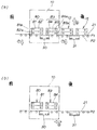
図12(a),(b)は従来のプレス加工機の金型交換装置の平面図であり、金型交換装置100でプレス加工機101の金型102を交換する例について説明したものである。
(a)において、金型交換装置100のシリンダ103を操作することにより、プレス加工機101の片側101aに搬送台車104の第1載置面105を寄せる。この状態で、プレス加工機101の金型102を白抜き矢印の如く第1載置面105に移載する。
【0004】
(b)において、金型102を第1載置面105に移載した後、シリンダ103で搬送台車104をレール107,107に沿って移動し、第2載置面106をプレス加工機101の片側101aに寄せる。
この状態で、第2載置面104の新たな金型108を矢印の如くプレス加工機101に移動し、新たな金型108をプレス加工機101に取付ける。これにより、金型102を新たな金型108に交換する作業が完了する。
【0005】
【発明が解決しようとする課題】
ところで、プレス加工機のなかには複数の金型、特に2個の金型を並設したものがある。これらの金型を従来の金型交換装置100で交換するためには、先ず2個の金型のうちの一方の金型を交換し、次に他方の金型を交換する必要がある。このため、金型の交換作業を2回行う必要があるので、金型の交換に時間がかかる。
【0006】
ここで、金型の交換時間を短くする方法として、プレス加工機の近傍に金型交換装置100を2セット用意するという対応も考えられる。しかし、金型交換装置100を2セット用意する必要があるので設備費が嵩む。
【0007】
そこで、本発明の目的は、2個の金型交換を時間をかけないで行うことができ、かつ設備費を抑えることができるプレス加工機の金型交換装置を提供することにある。
【0008】
【課題を解決するための手段】
上記目的を達成するために本発明の請求項1は、2個の金型を並設したプレス加工機の金型交換装置であって、この金型交換装置は、前記プレス加工機に取付けた前記2個の金型の下方を横断させる様に設けたキャリア案内レールと、このキャリア案内レールに走行自在に載せるとともに前記2個の金型に対応させた一対のキャリアと、前記一対のキャリアのうち個々のキャリアに上方へ突出可能に2個ずつ設けた係合部材と、前記2個の金型側に各々設けた被係合部に前記係合部材を突出させる係合部材駆動手段と、前記一対のキャリアを前記キャリア案内レールに沿って前記プレス加工機内外へ移動するキャリア移動手段と、からなり、前記1個のキャリアに設けた前記2個の係合部材を前記係合部材駆動手段で前記2個の金型側の各被係合部に突出させ、前記2個の金型の両方を前記1個のキャリアで前記プレス加工機から搬出入可能とし、前記1個のキャリアに設けた前記2個の係合部材の一方を前記2個の金型側の一方の被係合部に突出させ、前記2個の金型の一方を前記1個のキャリアで前記プレス加工機から搬出入可能としたことを特徴とする。
【0009】
一対のキャリア及び係合部材で2個の金型の両方をプレス加工機から搬出入する構成とした。このため、プレス加工機から2個の金型を同時に搬出し、かつプレス加工機に新たな2個の金型を同時に搬入することができる。従って、1回の交換作業で2個の金型を交換することができるので、金型の交換時間を短くすることができる。
【0010】
加えて、一対のキャリア及び係合部材で2個の金型の一方をプレス加工機から搬出入する構成とした。このため、1個の金型のみを必要に応じて交換することもできる。従って、2個の金型を同時に交換する設備と、1個の金型のみを交換する設備とを一つの金型交換装置で併用することができる。
【0011】
請求項2は、2個の金型を並設したプレス加工機の金型交換装置であって、この金型交換装置は、前記プレス加工機に取付けた前記2個の金型の下方を横断させる様に設けたローラテーブル並びにキャリア案内レールと、このキャリア案内レールに走行自在に載せるとともに前記2個の金型に対応させた一対のキャリアと、前記一対のキャリアのうち個々のキャリアに上方へ突出可能に2個ずつ設けた係合部材と、前記2個の金型側に各々設けた被係合部に前記係合部材を突出させる係合部材駆動手段と、前記一対のキャリアを前記キャリア案内レールに沿って前記プレス加工機内外へ移動するキャリア移動手段と、前記ローラテーブルの上面を前記一対のキャリアの上面より上又は下に起動するローラテーブル昇降手段と、からなり、前記1個のキャリアに設けた前記2個の係合部材を前記係合部材駆動手段で前記2個の金型側の各被係合部に突出させ、前記2個の金型の両方を前記1個のキャリアで前記プレス加工機から搬出入可能とし、前記1個のキャリアに設けた前記2個の係合部材の一方を前記2個の金型側の一方の被係合部に突出させ、前記2個の金型の一方を前記1個のキャリアで前記プレス加工機から搬出入可能としたことを特徴とする。
【0012】
一対のキャリア及び係合部材で2個の金型の両方をプレス加工機から搬出入する構成とした。このため、プレス加工機から2個の金型を同時に搬出し、かつプレス加工機に新たな2個の金型を同時に搬入することができる。従って、1回の交換作業で2個の金型を交換することができるので、金型の交換時間を短くすることができる。
【0013】
加えて、一対のキャリア及び係合部材で2個の金型の一方をプレス加工機から搬出入する構成とした。このため、1個の金型のみを必要に応じて交換することもできる。従って、2個の金型を同時に交換する設備と、1個の金型のみを交換する設備とを一つの金型交換装置で併用することができる。
【0014】
また、昇降手段でローラテーブルを昇降自在な構成にした。このため、ローラテーブルを金型取付位置まで上昇させることができる。従って、プレス加工機の金型をローラテーブルに容易に移載することができ、かつローラテーブルの金型をプレス加工機に容易に取付けることができる。
【0015】
加えて、ローラテーブルを昇降自在な構成にしたことで、ローラテーブルを金型取付位置から下降させることができる。このため、ローラテーブルを金型から離すことができる。従って、プレス加工機でプレス加工を行う際に、プレス圧がローラテーブルに伝わることを防ぐことができる。
【0016】
【発明の実施の形態】
本発明の実施の形態を添付図に基づいて以下に説明する。なお、図面は符号の向きに見るものとする。
図1は本発明に係るプレス加工機の金型交換装置の斜視図である。
プレス加工機10は、加工機本体11(想像線で示す)に2個の金型12,15を並設し、金型12の上型13を係止ピン13a,13aで加工機本体11に取付け、金型12の下型14を係止ピン14a,14aで加工機本体11に取付け、金型15の上型16を係止ピン16a,16aで加工機本体11に取付け、金型15の下型17を係止ピン17a,17aで加工機本体11に取付けた装置である。
【0017】
プレス加工機10によれば、金型12,15のそれぞれの上型13,16を上死点まで上昇した後、一例としてブランク材(図示しない)をそれぞれの下型14,17にセットし、この状態で上型13,16を下死点まで下降することによりそれぞれのブランク材を成形品にプレス成形することができる。
【0018】
このプレス加工機10は、プレス成形する成形品の変更に合せて金型12,15を交換するために、金型12,15の下方に前後に延びる金型交換装置20を備える。以下、金型交換装置20について説明する。
【0019】
金型交換装置20は、金型12,15の下方にローラテーブル21並びにキャリア案内レール25を備え、キャリア案内レール25に一対のキャリア(前後のキャリア)30,31を移動自在に配置し、前キャリア30に前後の係合部材45,46(図2に示す)を設けるとともに係合部材45,46を突出させる前係合部材駆動手段50(図5に示す)を設け、後キャリア31に前後の係合部材47,48(図2に示す)を設けるとともに係合部材47,48を突出させる後係合部材駆動手段(図示しない)を設け、前後のキャリア30,31をキャリア案内レール25に沿って移動するキャリア移動手段60を備え、ローラテーブル21及び前後のキャリア30,31を上又は下に起動する昇降手段70を備える。
【0020】
なお、図示しない後係合部材駆動手段は、前係合部材駆動手段50と同一構成部材であり、以下、前係合部材駆動手段50について詳しく説明して、後係合部材駆動手段の説明は省略する。
【0021】
ローラテーブル21並びにキャリア案内レール25は、プレス加工機10に取付けた2個の金型12,15の下方を横断させる様に設けた部材である。
前後のキャリア30,31は、キャリア案内レール25に走行自在に載せるとともに2個の金型12,15に対応させた位置に配置した部材である。
キャリア移動手段60は、前後のキャリア30,31をキャリア案内レール25に沿ってプレス加工機10内外へ移動する手段である。
昇降手段70は、ローラテーブル21及び前後のキャリア30,31を上又は下に起動する手段である。
以下、これらの構成部材について次図で詳しく説明する。
【0022】
図2は本発明に係るプレス加工機の金型交換装置の分解斜視図である。
ローラテーブル21は、図1に示すように一定間隔をおいて配置した左右のローラ部22,23からなり、これらのローラ部22,23は上面に複数のローラ24・・・(・・・は複数個を示す)を備える。
キャリア案内レール25は、前後のキャリア30,31を左右側から挟み込むように配置した左右のレール部材26,27からなる。左右のレール部材26,27は、略コ字型に形成することで左右のレール部材26,27にそれぞれ左右の案内溝26a,27a(図3も参照)を形成したものである。
【0023】
前キャリア30は、矩形箱体32に左右の走行ローラ33・・・を備える。左右の走行ローラ33・・・をキャリア案内レール25の案内溝26a,27aに配置することにより、前キャリア30をキャリア案内レール25に沿って移動することができる。
前キャリア30の前後端には各々前後の係合ピン45,46を設けた。前後の係合ピン45,46は前キャリア30の上面から上方へ突出可能な部材である。
【0024】
また、後キャリア31は、前キャリア30と同一構成部材であり、矩形箱体32に左右の走行ローラ33・・・を備える。左右の走行ローラ33・・・をキャリア案内レール25の案内溝26a,27aに配置することにより、後キャリア30を前キャリア30と同様にキャリア案内レール25に沿って移動することができる。
後キャリア31の前後端には各々前後の係合ピン47,48を設けた。前後の係合ピン47,48は後キャリア31の上面から上方へ突出可能な部材である。
【0025】
キャリア移動手段60は、前キャリア30をキャリア案内レール25に沿って移動する前キャリア移動手段61と、後キャリア31をキャリア案内レール25に沿って移動する後キャリア移動手段62とからなる。
前キャリア移動手段61は、前キャリア30の前端に前駆動チェーン63の前端をつなぎ、この前駆動チェーン63を前スプロケット64aにかけ、前スプロケット64aにかけた前駆動チェーン63を前チェーンガイド65に収納し、前スプロケット64aを駆動する前駆動モータ66a及び前減速機66bを有する。
【0026】
前駆動チェーン63は、一般にプッシュプルチェーンといわれるチェーンであり、図4及び図5に示すようにキャリア案内レール25に沿って直線上に配列した際に、各リンクプレート63a・・・を直線状態に保つために、一例として係止部63b・・・を備える。
【0027】
このため、前駆動モータ66aで前スプロケット64aを反時計回り方向に回転することにより、前駆動チェーン63で前キャリア30をキャリア案内レール25に沿って前方に引くことができる。
加えて、前駆動モータ66aで前スプロケット64aを時計回り方向に回転することにより、前駆動チェーン63で前キャリア30をキャリア案内レール25に沿って後方に押すことができる。
【0028】
後キャリア移動手段62は、後キャリア31の後端に後駆動チェーン67の前端をつなぎ、この後駆動チェーン67を後スプロケット64b(図1に示す)にかけ、後スプロケット64bにかけた後駆動チェーン67を後チェーンガイド68に収納し、後スプロケット64bを駆動する後駆動モータ69a及び後減速機69bを有する。
【0029】
後駆動チェーン67は、前駆動チェーン63と同じプッシュプルチェーンであり、キャリア案内レール25に沿って直線上に配列した際に、各リンクプレートを直線状態に保つために、一例として係止部を備える。
【0030】
このため、後駆動モータ69aで後スプロケット64bを時計回り方向に回転することにより、後駆動チェーン67で後キャリア31をキャリア案内レール25に沿って後方に引くことができる。
加えて、後駆動モータ69aで後スプロケット64bを反時計回り方向に回転することにより、後駆動チェーン67で後キャリア31をキャリア案内レール25に沿って前方に押すことができる。
【0031】
昇降手段70は、ローラテーブル21の左ローラ部22,23の前後端にそれぞれ4本のエアシリンダ71・・・を備え、かつローラテーブル21の右ローラ部22,23の前後端にそれぞれ4本のエアシリンダ71・・・を備える。
これらのエアシリンダ71・・・を、それぞれアジャスタボルト72・・・で基台73(図3に示す)に取付けることにより、エアシリンダ71・・・でローラテーブル21を昇降することができる。なお、ローラテーブル21の昇降については図3で詳しく説明する。
【0032】
キャリア案内レール25の右レール部材27には、一例としてリミットスイッチ(接触式位置検出スイッチ)76・・・を所定間隔をおいて配置する。リミットスイッチ76・・・が前後のキャリア30,31に当接することにより、前後のキャリア30,31の位置を検出することができる。
【0033】
リミットスイッチ76・・・で前キャリア30の位置を検出した際に、キャリア移動手段60の前駆動モータ66aを静止させることにより、前キャリア30を所定位置に静止させることができる。
また、リミットスイッチ76・・・で後キャリア31の位置を検出した際に、キャリア移動手段60の後駆動モータ69aを静止させることにより、後キャリア31を所定位置に静止させることができる。
【0034】
加えて、前後のキャリア30,31で金型を搬送している場合には、リミットスイッチ76・・・で前後のキャリア30,31の位置を検出した際に、ローラテーブル21の表面から突出したストッパピン(図示しない)で、金型を静止させる構成にした。このため、金型を所定位置に正確に静止させることができる。
【0035】
図3は図1の3−3線断面図であり、ローラテーブル21の左右のローラ部22,23を一定間隔をおいて複数のクロスメンバー28・・・(1本のみを図示する)で連結し、これらのクロスメンバー28・・・の中央にキャリア案内レール25の左右のレール部材26,27をそれぞれ左右の支持プレート29,29を介して取付け、左右のレール部材26,27間に前後のキャリア30,31(後キャリア31は図2に示す)を配置することで、これらのキャリア30,31の走行ローラ33・・・をそれぞれ左右の案内溝26a,27aに配置した状態を示す。
【0036】
左右のローラ部22,23は、左右のフレーム22a,23aの上端に複数のローラ24・・・を水平に配置したものである(図2も参照)。これにより、図1に示す金型12,15をローラテーブル21に沿って前後方向に搬送することができる。
この前キャリア30に左側壁に検出ブロック30aを備える。この検出ブロック30aをリミットスイッチ76に当接させることにより、リミットスイッチ76を作動させる。これにより、前キャリア30の位置を検出することができる。
【0037】
さらに、この図は、左右のフレーム22a,23aにそれぞれ左右のエアシリンダ71・・・のシリンダロッド71b・・・を取付け、左右のシリンダ部71a・・・をそれぞれ左右のアジャスタボルト72・・・及び左右の支持ブラケット74・・・,75・・・(図では各々1個のみ示す)を介して基台73に取付けた状態を示す。
【0038】
これにより、昇降手段70の左右のエアシリンダ71・・・を作動することにより、ローラテーブル21及び前後のキャリア30,31(後キャリア31は図2に示す)を金型取付位置P1及び退避位置P2間で昇降させることができる。
なお、金型取付位置P1及び退避位置P2については図6〜図11の作用の説明で詳しく説明する。
【0039】
図4は本発明に係る金型交換装置を構成するキャリアの拡大図であり、前キャリア30を示す斜視図である。なお、後キャリア31は前キャリア30と同一構成部材なので、以下、前キャリア30について説明して後キャリア31についての説明は省略する。
【0040】
前キャリア30の矩形箱体32は、矩形状に形成した左右の側壁34,35を一定間隔をおいて配置し、左右の側壁34,35間の前端に前上部ブロック36及び前下ブロック37を取付け、左右の側壁34,35間の中央に第1、第2の中央支持部材38,39を取付け、左右の側壁34,35間の後端に後上部ブロック41及び後下ブロック42(図5に示す)を取付け、左側壁34の下部に4個の左走行ローラ33・・・(1個のみを図示する)を設け、右側壁35の下部に4個の右走行ローラ33・・・を設けたものである。
なお、左右の走行ローラ33・・・は、それぞれ1本の軸43・・・で同軸上に取付けた部材である。
【0041】
左側壁34は、リミットスイッチ76(図1及び図3に示す)に当接する検出ブロック30aを備える。図3で説明したように検出ブロック30aがリミットスイッチ76に当接することで、リミットスイッチ76が作動して前キャリア30の位置を検出する。
前上部ブロック36は、前係合ピン45を昇降自在に挿入するための貫通孔36aを備える。また、後上部ブロック41は、後係合ピン46を昇降自在に挿入するための貫通孔41aを備える。
【0042】
図5は図4の5−5線断面図であり、前キャリア30内に前後の係合ピン45,46並びに前係合部材駆動手段50を設けた姿を示す。
前係合部材駆動手段50は、前後の係合ピン45,46を前キャリア30の上面から選択的に突出させる手段である。前後の係合ピン45,46を前キャリア30の上面から突出させることで、前後の係合ピン45,46を金型12,15の下型14,17側に設けたそれぞれの被係合部(すなわち、係合穴)18,19に差込むことができる。
【0043】
なお、図2に示す後キャリア31の後係合部材駆動手段は、前係合部材駆動手段50と同一構成部材であり、下型14,17の被係合部18,19に前後の係合部材47,48(図2に示す)を選択的に突出可能な手段である。
以下、前係合部材駆動手段50の構成について詳しく説明する。
【0044】
前係合部材駆動手段50は、前キャリア30に備えた前後の駆動部52,53からなる。
前駆動部52は、エアシリンダ54のシリンダ部54aをシリンダピン55で前キャリア30の第1ブラケット38aに取付け、シリンダロッド54bにロッドピン56で上下のアーム57,58を揺動自在に取付け、上アーム57の端部を上ピン57aで前係合ピン45に取付け、下アーム58の端部を下ピン58aで前ブラケット37aに取付けたものである。
第1ブラケット38aは第1中央支持部材38に取付けた部材であり、前ブラケット37aは前下ブロック37に取付けた部材である。
【0045】
よって、エアシリンダ54を作動させてシリンダロッド54bを進出させることで、上下のアーム57,58が直線状に開いて前係合ピン45を前キャリア30の上面から突出させる。これにより、前係合ピン45を下型14の被係合部18に係合させることができる。
一方、エアシリンダ54のシリンダロッド54bを後退させることで、前係合ピン45を前キャリア30の上面まで下降させて下型14の被係合部18から退避させることができる。
【0046】
後駆動部53は、エアシリンダ54のシリンダ部54aをシリンダピン55で前キャリア30の第2ブラケット39aに取付け、シリンダロッド54bにロッドピン56で上下のアーム57,58を揺動自在に取付け、上アーム57の端部を上ピン57aで後係合ピン46に取付け、下アーム58の端部を下ピン58aで後ブラケット42aけたものである。
第2ブラケット39aは第2中央支持部材39に取付けた部材であり、後ブラケット42aは後下ブロック42に取付けた部材である。
【0047】
よって、エアシリンダ54を作動させてシリンダロッド54bを後退させることで、上下のアーム57,58が直線状からく字形に閉じて後係合ピン46を前キャリア30の上面まで下降させる。これにより、後係合ピン46を下金型17の被係合部19から退避させることができる。
一方、エアシリンダ54のシリンダロッド54bを進出させることで、後係合ピン46を前係合ピン45と同様に前キャリア30の上面から突出させて下型17の被係合部19に係合させることができる。
【0048】
また、前キャリア30の前端には、左右の走行ローラ33を支える軸43を介して前駆動チェーン63の前端部を取付ける。
なお、前キャリア30は、矩形箱体32の底板32aにガイドブロック32bを備える。
【0049】
次に、プレス加工機の金型交換装置20の作用について説明する。先ず、2個の金型の両方をプレス加工機から搬出入する例を図6〜図8に基づいて説明する。
図6(a),(b)は本発明に係るプレス加工機の金型交換装置の第1作用説明図である。
(a)において、ローラテーブル21及び前後のキャリア30,31を待機位置P2に待機させた状態で、プレス加工機10を操作して金型12,15の上型13,16を矢印▲1▼の如く下降する。次に、キャリア移動手段60の前後の駆動モータ66a,69a(図2に示す)で前後のキャリア30,31を矢印▲2▼の如く前方に移動する。
【0050】
(b)において、後キャリア31の前後端がそれぞれ金型12の後端及び金型15の前端に重なる位置に到達した際に、前後のキャリア30,31に当接したリミットスイッチ76,76が作動して前後の駆動モータ66a,69aを停止する。
次に、新たな金型80,83を矢印▲3▼の如くローラテーブル21に載せる。この際、新たな金型80の後端を前キャリア30の前端に重ね、新たな金型83の前端を前キャリア30の後端に重ねる。
この状態で、昇降手段70のエアシリンダ71を作動してローラテーブル21及び前後のキャリア30,31を待機位置P2から金型取付位置P1まで矢印▲4▼の如く上昇する。
【0051】
図7(a),(b)は本発明に係るプレス加工機の金型交換装置の第2作用説明図である。
(a)において、ローラテーブル21及び前後のキャリア30,31を金型取付位置P1に静止させる。次に、加工機本体11から上型13の係止ピン13a,13aを外すとともに下型14の係止ピン14a,14aを外す。よって、金型12をローラテーブル21に載せることができる。
【0052】
続いて、加工機本体11から上型16を係止ピン16a,16aを外すとともに下型17の係止ピン17a,17aを外す。よって、金型15をローラテーブル21に載せることができる。
このように、ローラテーブル21を金型取付位置P1まで上昇させることができるので、プレス加工機10の金型12,15をローラテーブル21に容易に移載することができる。
【0053】
金型12,15をローラテーブル21に載せた後、前キャリア30の前後の係合ピン45,46を突出させる。これにより、金型80,83の下型82,85に形成した被係合部86,86に前後の係合ピン45,46を係合させる。
同時に、後キャリア31の前後の係合ピン47,48を突出させる。これにより、金型12,15の下型14,17に形成した被係合部18,18に前後の係合ピン47,48を係合させる。
【0054】
なお、被係合部18,18は、図5に示すように係合ピン45〜48にタイトに係合する係合穴であるが、作用の説明では理解を容易にするために大きく図示して説明する。
また、被係合部86,86は、被係合部18,18と同じサイズの係合穴であるが、同様の理由で大きく図示して説明する。
【0055】
被係合部86,86に前後の係合ピン45,46を係合させるとともに、被係合部18,18に前後の係合ピン47,48を係合させた後、キャリア移動手段60の前後の駆動モータ66a,69a(図2に示す)で前後のキャリア30,31を矢印▲5▼の如く後方に移動する。
よって、プレス加工機10内の金型12,15をローラテーブル21に沿ってプレス加工機10から搬出する方向に移動するとともに、金型80,83をローラテーブル21に沿ってプレス加工機10に搬入する方向に移動する。
【0056】
(b)において、前キャリア30がプレス加工機10の中央に到達した際に、前後のキャリア30,31に当接した検出リミットスイッチ76,76が作動して前後の駆動モータ66a,69aを停止する。よって、金型80,83をプレス加工機10の取付位置に静止させることができる。
次に、前キャリア30の前後の係合ピン45,46を下げて下型82,85の被係合部86,86から退避させる。同時に、後キャリア31の前後の係合ピン47,48を下げて下型14,17の被係合部18,18から退避させる。
【0057】
図8(a),(b)は本発明に係るプレス加工機の金型交換装置の第3作用説明図である。
(a)において、金型80の上下の型81,82に備えた係止ピン81a,82aをプレス加工機10に取付けるとともに、金型83の上下の型84,85に備えた係止ピン84a,85aをプレス加工機10に取付ける。
ここで、ローラテーブル21を金型取付位置P1に保持しているので、ローラテーブル21の金型80,83をプレス加工機10に容易に取付けることができる。
【0058】
続いて、金型12,15をローラテーブル21から矢印▲6▼の如く取り除く。次に、昇降手段70のエアシリンダ71を作動してローラテーブル21及び前後のキャリア30,31を金型取付位置P1から待機位置P2まで矢印▲7▼の如く下降する。
【0059】
(b)において、キャリア移動手段60の前後の駆動モータ66a,69a(図2に示す)で前後のキャリア30,31を矢印▲8▼の如く前方に移動する。
前キャリア30がプレス加工機10の左端に到達するとともに、後キャリア31がプレス加工機10の右端に到達し際に、前後のキャリア30,31に当接したリミットスイッチ76,76が作動して前後の駆動モータ66a,69a(図2に示す)を停止する。よって、前後のキャリア30,31を図6(a)の位置に静止させることができる。
【0060】
これにより、2個の金型12,15をプレス加工機10から搬出し、かつ2個の金型80,83をプレス加工機10に搬入する工程を完了する。
金型の交換完了後、プレス加工機10で上型81,84を昇降させることにより、金型80,83でプレス加工を行う。
【0061】
この際、ローラテーブル21を金型取付位置P1から下降させることで、ローラテーブル21を金型80,83から離すことができる。よって、プレス加工機10を作動させる際に、プレス圧がローラテーブル21に伝わることを防ぐことができる。
【0062】
以上、図6〜図8で説明したように前後のキャリア30,31で2個の金型12,15をプレス加工機10から同時に搬出するとともに、2個の新たな金型80,83をプレス加工機10に同時に搬入することができる。このため、2個の金型12,15の交換を時間をかけないで行うことができる。
【0063】
なお、図6〜図8で説明した作用では、前後の駆動モータ66a,69a(図2に示す)を同時に駆動することで前後のキャリア30,31を一緒に移動する例について説明したが、前後の駆動モータ66a,69aを時間をずらして駆動することにより前後のキャリア30,31を個別に移動してもよい。
【0064】
次に、2個の金型の一方のみをプレス加工機から搬出入する例を図9〜図11に基づいて説明する。
図9(a),(b)は本発明に係るプレス加工機の金型交換装置の第4作用説明図である。
(a)において、ローラテーブル21及び前後のキャリア30,31を待機位置P2に待機させた状態で、プレス加工機10を操作して金型12,15の上型13,16を矢印aの如く下降する。次に、キャリア移動手段60の後駆動モータ69aで後キャリア31を矢印bの如く前方に移動する。
【0065】
(b)において、後キャリア31の前後端がそれぞれ金型12の後端及び金型15の前端に重なる位置に到達した際に、後キャリア31に当接したリミットスイッチ76が作動して後駆動モータ69aを停止する。
次に、昇降手段70のエアシリンダ71を作動してローラテーブル21及び前後のキャリア30,31を待機位置P2から金型取付位置P1まで矢印cの如く上昇する。
【0066】
図10(a),(b)は本発明に係るプレス加工機の金型交換装置の第5作用説明図である。
(a)において、ローラテーブル21及び前後のキャリア30,31を金型取付位置P1に静止させる。次に、加工機本体11から上型16を係止ピン16a,16aを外すとともに下型17の係止ピン17a,17aを外す。これにより、金型15をローラテーブル21に載せることができる。
ローラテーブル21を金型取付位置P1まで上昇させることができるので、プレス加工機10の金型15をローラテーブル21に容易に移載することができる。
【0067】
金型15をローラテーブル21に載せた後、後キャリア31の後係合ピン48を突出させる。よって、金型15の下型17に形成した被係合部18に後係合ピン48を係合させる。
この状態で、キャリア移動手段60の後駆動モータ69a(図2に示す)で後キャリア31を矢印dの如く後方に移動する。これにより、プレス加工機10内の金型15をローラテーブル21に沿ってプレス加工機10から搬出する方向に移動する。
【0068】
(b)において、後キャリア31がプレス加工機10から搬出して所定位置に到達した際に、後キャリア31に当接した検出リミットスイッチ76が作動して後駆動モータ69aを停止する。よって、金型80,83をプレス加工機10の取付位置に静止させることができる。
次に、後キャリア31の後係合ピン48を下げて下型17の被係合部18から退避させる。次いで、金型15を矢印eの如くローラテーブル21から取り除く。
【0069】
図11(a),(b)は本発明に係るプレス加工機の金型交換装置の第6作用説明図である。
(a)において、新たな金型83を矢印fの如くローラテーブル21に載せ、新たな金型83の前端を後キャリア31の後端に重ねる。次に、後キャリア31の後係合ピン48を突出させて、金型83の下型85に形成した被係合部86に後係合ピン48を係合させる。
次いで、キャリア移動手段60の後駆動モータ69a(図2に示す)で後キャリア31を矢印gの如く前方に移動する。
【0070】
(b)において、後キャリア31で金型83をプレス加工機10内の所定位置まで搬入した際に、後キャリア31に当接したリミットスイッチ76が作動して後駆動モータ69a(図2に示す)を停止する。
次に、後キャリア31の後係合ピン48を下げて下型85の被係合部86から退避させる。
【0071】
この状態で、金型83の上下の型84,85に備えた係止ピン84a,85aをプレス加工機10に取付ける。
ここで、ローラテーブル21を金型取付位置P1に保持しているので、ローラテーブル21の金型83をプレス加工機10に容易に取付けることができる。
次に、昇降手段70のエアシリンダ71を作動してローラテーブル21及び前後のキャリア30,31を金型取付位置P1から待機位置P2まで矢印hの如く下降する。
【0072】
続いて、キャリア移動手段60の後駆動モータ69aで後キャリア31を後方に移動して、後キャリア31を図9(a)の状態に静止させる。
これにより、1個の金型15をプレス加工機10から搬出し、かつ1個の金型83をプレス加工機10に搬入する工程を完了する。
【0073】
金型の交換完了後、プレス加工機10で上型13,84を昇降させることにより、金型12,83でプレス加工を行う。
この際、ローラテーブル21を金型取付位置P1から下降させることで、ローラテーブル21を金型12,83から離すことができる。よって、プレス加工機10を作動させる際に、プレス圧がローラテーブル21に伝わることを防ぐことができる。
【0074】
以上、図9〜図11で説明したように後キャリア31を使用することにより、1個の金型15のみをプレス加工機10から搬出して、1個の新たな金型83をプレス加工機10に搬入することができる。
なお、図9〜図11では後キャリア31を使用した例について説明したが、前キャリア30を使用することにより、1個の金型12のみをプレス加工機10から搬出して、1個の新たな金型80をプレス加工機10に搬入することも可能である。
【0075】
このように、金型交換装置20によれば、2個の金型12,15を同時に交換する設備と、1個の金型15のみ又は1個の金型12のみを交換する設備とを一つの金型交換装置20で併用することができる。従って、金型交換装置20の簡素化を図ることができる。
【0076】
なお、前記実施の形態では、前後のキャリア30,31を駆動する前後の駆動チェーン63,67として、いわゆるプッシュプルチェーンを使用した例について説明したが、これに限らないで、環状のチェーンを前後のスプロケット64a,64bにかけ、このチェーンに前後のキャリア30,31をつなぐようにしてもよい。
また、前記実施の形態では、前後の係合部材として前後の係合ピンを使用した例について説明したが、その他の係合部材としてフックなどを使用することも可能である。
【0077】
【発明の効果】
本発明は上記構成により次の効果を発揮する。
請求項1は、一対のキャリア及び係合部材で2個の金型の両方をプレス加工機から搬出入する構成とした。よって、プレス加工機から2個の金型を同時に搬出し、かつプレス加工機に新たな2個の金型を同時に搬入することができる。このため、1回の交換作業で2個の金型を交換することができるので、金型の交換時間を短くすることができる。従って、プレス加工機の稼働率を高めて生産性の向上を図ることができる。
【0078】
加えて、一対のキャリア及び係合部材で2個の金型の一方をプレス加工機から搬出入する構成とした。よって、1個の金型のみを必要に応じて交換することもできる。このため、2個の金型を同時に交換する設備と、1個の金型のみを交換する設備とを一つの金型交換装置で併用することができる。
このため、金型交換装置の簡素化を図ることができるので、設備費を抑えることができる。
【0079】
請求項2は、一対のキャリア及び係合部材で2個の金型の両方をプレス加工機から搬出入する構成とした。よって、プレス加工機から2個の金型を同時に搬出し、かつプレス加工機に新たな2個の金型を同時に搬入することができる。このため、1回の交換作業で2個の金型を交換することができるので、金型の交換時間を短くすることができる。従って、プレス加工機の稼働率を高めて生産性の向上を図ることができる。
【0080】
加えて、一対のキャリア及び係合部材で2個の金型の一方をプレス加工機から搬出入する構成とした。よって、1個の金型のみを必要に応じて交換することもできる。このため、2個の金型を同時に交換する設備と、1個の金型のみを交換する設備とを一つの金型交換装置で併用することができる。
このため、金型交換装置の簡素化を図ることができるので、設備費を抑えることができる。
【0081】
また、昇降手段でローラテーブルを昇降自在な構成にした。よって、ローラテーブルを金型取付位置まで上昇させることができる。このため、プレス加工機の金型をローラテーブルに容易に移載することができ、かつローラテーブルの金型をプレス加工機に容易に取付けることができる。従って、金型の交換時間をより短くすることができる。
【0082】
加えて、ローラテーブルを昇降自在な構成にしたことで、ローラテーブルを金型取付位置から下降させることができる。よって、ローラテーブルを金型から離すことができる。このため、プレス加工機でプレス加工を行う際に、プレス圧がローラテーブルに伝わることを防ぐことができる。従って、ローラテーブルの耐久性を確保することができる。
【図面の簡単な説明】
【図1】本発明に係るプレス加工機の金型交換装置の斜視図
【図2】本発明に係るプレス加工機の金型交換装置の分解斜視図
【図3】図1の3−3線断面図
【図4】本発明に係る金型交換装置を構成するキャリアの拡大図
【図5】図4の5−5線断面図
【図6】本発明に係るプレス加工機の金型交換装置の第1作用説明図
【図7】本発明に係るプレス加工機の金型交換装置の第2作用説明図
【図8】本発明に係るプレス加工機の金型交換装置の第3作用説明図
【図9】本発明に係るプレス加工機の金型交換装置の第4作用説明図
【図10】本発明に係るプレス加工機の金型交換装置の第5作用説明図
【図11】本発明に係るプレス加工機の金型交換装置の第6作用説明図
【図12】従来のプレス加工機の金型交換装置
【符号の説明】
10…プレス加工機、12,15,80,83…金型、18,86…被係合部、20…プレス加工機の金型交換装置、21…ローラテーブル、25…キャリア案内レール、30…前キャリア(一対のキャリアの一方)、31…後キャリア(一対のキャリアの他方)、45,47…係合部材(前係合ピン)、46,48…係合部材(後係合ピン)、50…係合部材駆動手段(前係合部材駆動手段)、60…キャリア移動手段、61…前キャリア移動手段、62…後キャリア移動手段、70…昇降手段。[0001]
BACKGROUND OF THE INVENTION
The present invention relates to a die changing device for a press machine for exchanging a die attached to the press machine.
[0002]
[Prior art]
The press machine is provided with a replaceable die in order to change the die in accordance with a change in a molded product to be press-formed. As an example, a mold exchanging apparatus for exchanging molds has been proposed in Utility Model Registration No. 2533779 “Mold Exchanging Apparatus for Processing Machines”. The main part of the publication will be described below with reference to the following figure. However, the code was re-assigned.
[0003]
FIGS. 12A and 12B are plan views of a conventional mold exchanging device for a press working machine, and illustrate an example in which the die 102 of the
In (a), by operating the
[0004]
In (b), after the
In this state, the
[0005]
[Problems to be solved by the invention]
Incidentally, some press machines have a plurality of dies, particularly two dies arranged side by side. In order to replace these molds with the conventional
[0006]
Here, as a method for shortening the mold exchange time, a method of preparing two sets of the
[0007]
SUMMARY OF THE INVENTION An object of the present invention is to provide a die changer for a press machine that can change two dies without taking time, and can reduce equipment costs.
[0008]
[Means for Solving the Problems]
In order to achieve the above object, claim 1 of the present invention is a die changer for a press machine in which two dies are arranged side by side. Said Attached to press machine The two A carrier guide rail provided so as to cross the lower side of the mold, a pair of carriers that are placed on the carrier guide rail so as to run freely and correspond to the two molds, The pair Of career Individual career Can protrude upwards 2 pieces each An engagement member provided; and Two On the mold side Each The engaging member is provided on the provided engaged portion. Crush Engaging member driving means for taking out and the pair of carriers Said Along the carrier guide rail Said Carrier moving means for moving in and out of the press machine, One Career The two provided in Engagement member The engagement member driving means 2 molds ~ side of Let each of the engaged parts protrude, and the two molds Both The one with the one carrier Carry in / out from press machine One of the two engaging members provided on the one carrier is projected to one engaged portion on the two mold sides, and one of the two molds is It was possible to carry in and out from the press machine with a single carrier. It is characterized by that.
[0009]
It was set as the structure which carries in / out of both two metal mold | dies with a pair of carrier and an engaging member from a press processing machine. For this reason, two molds can be simultaneously carried out from the press machine, and two new molds can be carried into the press machine at the same time. Therefore, since two dies can be exchanged in one exchange operation, the exchange time of the dies can be shortened.
[0010]
In addition, one of the two molds is carried in and out of the press machine with a pair of carriers and engaging members. For this reason, only one metal mold | die can also be replaced | exchanged as needed. Therefore, the equipment for exchanging two molds simultaneously and the equipment for exchanging only one mold can be used together in one mold exchanging apparatus.
[0011]
Claim 2 is a die changer for a press machine in which two dies are arranged side by side. Said Attached to press machine The two A roller table and a carrier guide rail provided so as to cross the lower side of the mold, and a pair of carriers that are movably mounted on the carrier guide rail and correspond to the two molds; The pair Of career Individual career Can protrude upwards 2 pieces each An engagement member provided; and Two On the mold side Each The engaging member is provided on the provided engaged portion. Crush Engaging member driving means for taking out and the pair of carriers Said Along the carrier guide rail Said Carrier moving means that moves in and out of the press machine and the upper surface of the roller table The pair of Roller table elevating means that starts above or below the upper surface of the carrier, and One Career The two provided in Engagement member The engagement member driving means 2 molds ~ side of Let each of the engaged parts protrude, and the two molds Both The one with the one carrier Carry in / out from press machine One of the two engaging members provided on the one carrier is projected to one engaged portion on the two mold sides, and one of the two molds is It was possible to carry in and out from the press machine with a single carrier. It is characterized by that.
[0012]
It was set as the structure which carries in / out of both two metal mold | dies with a pair of carrier and an engaging member from a press processing machine. For this reason, two molds can be simultaneously carried out from the press machine, and two new molds can be carried into the press machine at the same time. Therefore, since two dies can be exchanged in one exchange operation, the exchange time of the dies can be shortened.
[0013]
In addition, one of the two molds is carried in and out of the press machine with a pair of carriers and engaging members. For this reason, only one metal mold | die can also be replaced | exchanged as needed. Therefore, the equipment for exchanging two molds simultaneously and the equipment for exchanging only one mold can be used together in one mold exchanging apparatus.
[0014]
Further, the roller table can be moved up and down by the lifting means. For this reason, the roller table can be raised to the mold mounting position. Therefore, the die of the press working machine can be easily transferred to the roller table, and the die of the roller table can be easily attached to the press working machine.
[0015]
In addition, since the roller table can be raised and lowered, the roller table can be lowered from the mold mounting position. For this reason, the roller table can be separated from the mold. Therefore, it is possible to prevent the press pressure from being transmitted to the roller table when the press working is performed by the press machine.
[0016]
DETAILED DESCRIPTION OF THE INVENTION
Embodiments of the present invention will be described below with reference to the accompanying drawings. The drawings are viewed in the direction of the reference numerals.
FIG. 1 is a perspective view of a die changing device of a press machine according to the present invention.
The
[0017]
According to the
[0018]
The
[0019]
The
[0020]
The rear engagement member driving means (not shown) is the same member as the front engagement member driving means 50. Hereinafter, the front engagement member driving means 50 will be described in detail, and the description of the rear engagement member driving means will be given. Omitted.
[0021]
The roller table 21 and the
The front and
The carrier moving means 60 is means for moving the front and
The lifting / lowering means 70 is a means for starting up the roller table 21 and the front and
Hereinafter, these constituent members will be described in detail with reference to the following drawings.
[0022]
FIG. 2 is an exploded perspective view of a die changer for a press machine according to the present invention.
As shown in FIG. 1, the roller table 21 is composed of left and
The
[0023]
The
Front and rear engagement pins 45 and 46 are provided at the front and rear ends of the
[0024]
The
Front and rear engagement pins 47 and 48 are provided at the front and rear ends of the
[0025]
The
The front carrier moving means 61 connects the front end of the
[0026]
The
[0027]
Therefore, the
In addition, the
[0028]
The rear carrier moving means 62 connects the front end of the
[0029]
The
[0030]
Therefore, the
In addition, the
[0031]
The elevating means 70 includes four
By attaching these
[0032]
As an example, limit switches (contact type position detection switches) 76... Are arranged on the
[0033]
When the position of the
Further, when the position of the
[0034]
In addition, when the molds are conveyed by the front and
[0035]
3 is a cross-sectional view taken along line 3-3 in FIG. 1, and the left and
[0036]
The left and
The
[0037]
Further, in this figure, the left and
[0038]
Accordingly, by operating the left and
The mold mounting position P1 and the retracted position P2 will be described in detail in the description of the operation of FIGS.
[0039]
FIG. 4 is an enlarged view of the carrier constituting the mold exchanging apparatus according to the present invention, and is a perspective view showing the
[0040]
The
The left and right traveling
[0041]
The
The front
[0042]
FIG. 5 is a cross-sectional view taken along line 5-5 of FIG. 4 and shows the
The front engagement member driving means 50 is means for selectively protruding front and rear engagement pins 45 and 46 from the upper surface of the
[0043]
2 is the same constituent member as the front engagement member drive means 50, and the front and rear engagement with the engaged
Hereinafter, the configuration of the front engagement member driving means 50 will be described in detail.
[0044]
The front engagement member drive means 50 includes front and
The
The first bracket 38 a is a member attached to the first
[0045]
Therefore, by operating the
On the other hand, by retracting the
[0046]
The
The
[0047]
Therefore, by operating the
On the other hand, by advancing the
[0048]
Further, the front end of the
The
[0049]
Next, the operation of the
6 (a) and 6 (b) are first operation explanatory views of the die changing device of the press machine according to the present invention.
In (a), with the roller table 21 and the front and
[0050]
In (b), when the front and rear ends of the
Next,
In this state, the
[0051]
FIGS. 7A and 7B are explanatory views of the second action of the die changing device of the press machine according to the present invention.
In (a), the roller table 21 and the front and
[0052]
Subsequently, the
Thus, since the roller table 21 can be raised to the mold attachment position P1, the
[0053]
After the
At the same time, the front and rear engaging
[0054]
The engaged
Further, the engaged
[0055]
The front and rear engaging
Therefore, the
[0056]
In (b), when the
Next, the front and rear engagement pins 45 and 46 of the
[0057]
FIGS. 8A and 8B are explanatory views of the third action of the die changing device of the press machine according to the present invention.
In (a), the locking pins 81 a and 82 a provided on the upper and
Here, since the roller table 21 is held at the die attachment position P1, the dies 80 and 83 of the roller table 21 can be easily attached to the
[0058]
Subsequently, the
[0059]
In (b), the front and
When the
[0060]
Thereby, the process of carrying out the two
After completion of the exchange of the dies, the upper dies 81 and 84 are moved up and down by the
[0061]
At this time, the roller table 21 can be separated from the
[0062]
As described above with reference to FIGS. 6 to 8, the two dies 12 and 15 are simultaneously carried out from the
[0063]
6 to 8, the example in which the front and
[0064]
Next, an example in which only one of the two molds is carried in and out of the press machine will be described with reference to FIGS.
9 (a) and 9 (b) are explanatory views of a fourth action of the die changer for a press machine according to the present invention.
In (a), with the roller table 21 and the front and
[0065]
In (b), when the front and rear ends of the
Next, the
[0066]
FIGS. 10 (a) and 10 (b) are explanatory views of a fifth operation of the die changing device of the press machine according to the present invention.
In (a), the roller table 21 and the front and
Since the roller table 21 can be raised to the mold attachment position P1, the
[0067]
After the
In this state, the
[0068]
In (b), when the
Next, the
[0069]
FIGS. 11 (a) and 11 (b) are explanatory views of a sixth action of the die changer for a press machine according to the present invention.
In (a), a
Next, the
[0070]
In FIG. 2B, when the
Next, the
[0071]
In this state, the locking pins 84 a and 85 a provided on the upper and
Here, since the roller table 21 is held at the die attachment position P1, the
Next, the
[0072]
Subsequently, the
Thereby, the process of carrying out one die 15 from the
[0073]
After completion of the exchange of the dies, the upper dies 13 and 84 are moved up and down by the
At this time, the roller table 21 can be separated from the
[0074]
As described above with reference to FIGS. 9 to 11, by using the
In addition, although the example using the
[0075]
As described above, according to the
[0076]
In the above embodiment, an example in which a so-called push-pull chain is used as the front and
Moreover, although the said embodiment demonstrated the example which used the front-and-back engagement pin as a front-and-back engagement member, it is also possible to use a hook etc. as another engagement member.
[0077]
【The invention's effect】
The present invention exhibits the following effects by the above configuration.
The first aspect of the present invention is configured such that both of the two molds are carried in and out of the press machine by the pair of carriers and the engaging member. Therefore, two dies can be simultaneously carried out from the press machine, and two new dies can be simultaneously carried into the press machine. For this reason, since two dies can be exchanged in one exchange operation, the exchange time of the dies can be shortened. Therefore, it is possible to improve the productivity by increasing the operating rate of the press machine.
[0078]
In addition, one of the two molds is carried in and out of the press machine with a pair of carriers and engaging members. Therefore, only one mold can be exchanged as necessary. For this reason, the equipment for exchanging two molds simultaneously and the equipment for exchanging only one mold can be used together in one mold exchanging apparatus.
For this reason, since a metal mold | die exchange apparatus can be simplified, installation cost can be held down.
[0079]
According to a second aspect of the present invention, both the two molds are carried in and out of the press machine by a pair of carriers and engaging members. Therefore, two dies can be simultaneously carried out from the press machine, and two new dies can be simultaneously carried into the press machine. For this reason, since two dies can be exchanged in one exchange operation, the exchange time of the dies can be shortened. Therefore, it is possible to improve the productivity by increasing the operating rate of the press machine.
[0080]
In addition, one of the two molds is carried in and out of the press machine with a pair of carriers and engaging members. Therefore, only one mold can be exchanged as necessary. For this reason, the equipment for exchanging two molds simultaneously and the equipment for exchanging only one mold can be used together in one mold exchanging apparatus.
For this reason, since a metal mold | die exchange apparatus can be simplified, installation cost can be held down.
[0081]
Further, the roller table can be moved up and down by the lifting means. Therefore, the roller table can be raised to the mold mounting position. For this reason, the metal mold | die of a press work machine can be easily transferred to a roller table, and the metal mold | die of a roller table can be easily attached to a press work machine. Therefore, the mold replacement time can be further shortened.
[0082]
In addition, since the roller table can be raised and lowered, the roller table can be lowered from the mold mounting position. Therefore, the roller table can be separated from the mold. For this reason, it is possible to prevent the pressing pressure from being transmitted to the roller table when the pressing is performed by the press machine. Therefore, the durability of the roller table can be ensured.
[Brief description of the drawings]
FIG. 1 is a perspective view of a die changer for a press machine according to the present invention.
FIG. 2 is an exploded perspective view of a die changer for a press machine according to the present invention.
3 is a sectional view taken along line 3-3 in FIG.
FIG. 4 is an enlarged view of a carrier constituting a mold exchanging apparatus according to the present invention.
5 is a cross-sectional view taken along line 5-5 of FIG.
FIG. 6 is a first operation explanatory diagram of a die changer for a press machine according to the present invention.
FIG. 7 is a second operation explanatory view of a die changer for a press machine according to the present invention.
FIG. 8 is an explanatory diagram of a third action of the die changing device of the press machine according to the present invention.
FIG. 9 is a fourth operation explanatory diagram of a die changer for a press machine according to the present invention.
FIG. 10 is an explanatory diagram of a fifth operation of the die changing device of the press machine according to the present invention.
FIG. 11 is an explanatory view of the sixth action of the die changing device of the press machine according to the present invention.
FIG. 12 shows a conventional die changing apparatus for a press machine.
[Explanation of symbols]
DESCRIPTION OF
Claims (2)
この金型交換装置は、
前記プレス加工機に取付けた前記2個の金型の下方を横断させる様に設けたキャリア案内レールと、
このキャリア案内レールに走行自在に載せるとともに前記2個の金型に対応させた一対のキャリアと、
前記一対のキャリアのうち個々のキャリアに上方へ突出可能に2個ずつ設けた係合部材と、
前記2個の金型側に各々設けた被係合部に前記係合部材を突出させる係合部材駆動手段と、
前記一対のキャリアを前記キャリア案内レールに沿って前記プレス加工機内外へ移動するキャリア移動手段と、からなり、
前記1個のキャリアに設けた前記2個の係合部材を前記係合部材駆動手段で前記2個の金型側の各被係合部に突出させ、前記2個の金型の両方を前記1個のキャリアで前記プレス加工機から搬出入可能とし、
前記1個のキャリアに設けた前記2個の係合部材の一方を前記2個の金型側の一方の被係合部に突出させ、前記2個の金型の一方を前記1個のキャリアで前記プレス加工機から搬出入可能としたことを特徴とするプレス加工機の金型交換装置。A die changer for a press machine in which two dies are arranged side by side,
This mold changer is
A carrier guide rails provided so as to cross the lower part of the two molds mounted on the press machine,
A pair of carriers that are movably mounted on the carrier guide rail and correspond to the two molds;
An engaging member provided two by two so as to be projected upward on the individual carriers of the pair of carrier,
And the engaging member drive means for out collision of the engaging member on each provided with the engaged portion in the two mold side,
A carrier moving means for moving the said press machine and out along the pair of carrier to the carrier guide rail consists,
The projecting said two engaging member provided on one carrier in each of the engaging portions of the two mold side by the engagement member driving means, the both of the two mold It is possible to carry in / out from the press machine with the one carrier ,
One of the two engaging members provided on the one carrier is protruded to one engaged portion on the two mold sides, and one of the two molds is connected to the one carrier. And a die changer for a press machine, wherein the die can be taken in and out of the press machine.
この金型交換装置は、
前記プレス加工機に取付けた前記2個の金型の下方を横断させる様に設けたローラテーブル並びにキャリア案内レールと、
このキャリア案内レールに走行自在に載せるとともに前記2個の金型に対応させた一対のキャリアと、
前記一対のキャリアのうち個々のキャリアに上方へ突出可能に2個ずつ設けた係合部材と、
前記2個の金型側に各々設けた被係合部に前記係合部材を突出させる係合部材駆動手段と、
前記一対のキャリアを前記キャリア案内レールに沿って前記プレス加工機内外へ移動するキャリア移動手段と、
前記ローラテーブルの上面を前記一対のキャリアの上面より上又は下に起動するローラテーブル昇降手段と、からなり、
前記1個のキャリアに設けた前記2個の係合部材を前記係合部材駆動手段で前記2個の金型側の各被係合部に突出させ、前記2個の金型の両方を前記1個のキャリアで前記プレス加工機から搬出入可能とし、
前記1個のキャリアに設けた前記2個の係合部材の一方を前記2個の金型側の一方の被係合部に突出させ、前記2個の金型の一方を前記1個のキャリアで前記プレス加工機から搬出入可能としたことを特徴とするプレス加工機の金型交換装置。A die changer for a press machine in which two dies are arranged side by side,
This mold changer is
A roller table as well as a carrier guide rail provided so as to cross the lower part of the two molds mounted on the press machine,
A pair of carriers that are movably mounted on the carrier guide rail and correspond to the two molds;
An engaging member provided two by two so as to be projected upward on the individual carriers of the pair of carrier,
And the engaging member drive means for out collision of the engaging member on each provided with the engaged portion in the two mold side,
A carrier moving means for moving the said press machine and out along the pair of carrier to the carrier guide rail,
Roller table elevating means for starting the upper surface of the roller table above or below the upper surface of the pair of carriers,
The projecting said two engaging member provided on one carrier in each of the engaging portions of the two mold side by the engagement member driving means, the both of the two mold It is possible to carry in / out from the press machine with the one carrier ,
One of the two engaging members provided on the one carrier is protruded to one engaged portion on the two mold sides, and one of the two molds is connected to the one carrier. And a die changer for a press machine, wherein the die can be taken in and out of the press machine.
Priority Applications (1)
| Application Number | Priority Date | Filing Date | Title |
|---|---|---|---|
| JP2000350174A JP4567174B2 (en) | 2000-11-16 | 2000-11-16 | Mold changer for press machine |
Applications Claiming Priority (1)
| Application Number | Priority Date | Filing Date | Title |
|---|---|---|---|
| JP2000350174A JP4567174B2 (en) | 2000-11-16 | 2000-11-16 | Mold changer for press machine |
Publications (2)
| Publication Number | Publication Date |
|---|---|
| JP2002153925A JP2002153925A (en) | 2002-05-28 |
| JP4567174B2 true JP4567174B2 (en) | 2010-10-20 |
Family
ID=18823454
Family Applications (1)
| Application Number | Title | Priority Date | Filing Date |
|---|---|---|---|
| JP2000350174A Expired - Fee Related JP4567174B2 (en) | 2000-11-16 | 2000-11-16 | Mold changer for press machine |
Country Status (1)
| Country | Link |
|---|---|
| JP (1) | JP4567174B2 (en) |
Families Citing this family (9)
| Publication number | Priority date | Publication date | Assignee | Title |
|---|---|---|---|---|
| ES2332963B1 (en) * | 2007-06-05 | 2011-05-13 | Universidad De Zaragoza | CARRIAGE CART FOR GRANULATOR FEED PRESSES. |
| KR200459821Y1 (en) * | 2009-08-28 | 2012-04-18 | 이명효 | A mold exchanging apparatus with an electric guide roller |
| KR200461302Y1 (en) | 2010-01-26 | 2012-07-04 | 이제선 | Mold stacker |
| CN103962490B (en) * | 2014-05-20 | 2016-02-03 | 中铁宝桥(南京)有限公司 | AT rail hot-forging forming guide-roller type mould changing device |
| FR3057800B1 (en) * | 2016-10-24 | 2020-11-06 | Dimeco | DEVICE FOR HANDLING A LOAD, IN PARTICULAR A PRESS TOOL, PRESS EQUIPPED WITH SUCH A DEVICE AND CORRESPONDING HANDLING PROCEDURE |
| JP7002174B2 (en) * | 2018-02-20 | 2022-02-04 | 株式会社Fts | Mold transfer structure |
| KR102335447B1 (en) * | 2021-07-29 | 2021-12-06 | 주식회사 에스비씨 | Mold changing cart with pusher device |
| CN114130904B (en) * | 2021-11-05 | 2023-09-01 | 广汽本田汽车有限公司 | Storage device for die switching |
| CN218399537U (en) * | 2022-08-16 | 2023-01-31 | 曼弗莱德智能制造(江苏)有限公司 | Press with lower die moving-out function |
Citations (1)
| Publication number | Priority date | Publication date | Assignee | Title |
|---|---|---|---|---|
| JPH0480618U (en) * | 1990-11-27 | 1992-07-14 |
Family Cites Families (5)
| Publication number | Priority date | Publication date | Assignee | Title |
|---|---|---|---|---|
| JPS5420447Y2 (en) * | 1974-07-23 | 1979-07-24 | ||
| JPS5838621A (en) * | 1981-02-20 | 1983-03-07 | Nissan Motor Co Ltd | Press device |
| US4503741A (en) * | 1982-07-26 | 1985-03-12 | The Warner & Swasey Company | Bridge type punch press |
| JPH01266993A (en) * | 1988-04-18 | 1989-10-24 | Komatsu Ltd | Press line |
| JP2939630B2 (en) * | 1990-02-23 | 1999-08-25 | 本田技研工業株式会社 | Mold changing device |
-
2000
- 2000-11-16 JP JP2000350174A patent/JP4567174B2/en not_active Expired - Fee Related
Patent Citations (1)
| Publication number | Priority date | Publication date | Assignee | Title |
|---|---|---|---|---|
| JPH0480618U (en) * | 1990-11-27 | 1992-07-14 |
Also Published As
| Publication number | Publication date |
|---|---|
| JP2002153925A (en) | 2002-05-28 |
Similar Documents
| Publication | Publication Date | Title |
|---|---|---|
| JP2762162B2 (en) | Transfer device of transfer press machine | |
| JP4567174B2 (en) | Mold changer for press machine | |
| CN203862718U (en) | Notching and necking all-in-one machine | |
| JP4269612B2 (en) | Transfer press work transfer device | |
| JP3285057B2 (en) | Automatic transfer device | |
| US4807456A (en) | Workpiece transfer device for press machine | |
| GB2199525A (en) | Workpiece transfer device for press machine | |
| JP4191316B2 (en) | Tire vulcanization equipment | |
| CN211895261U (en) | Full-servo paper towel grabbing manipulator | |
| JP2007105767A (en) | Press line and workpiece machining method in press line | |
| CN101306454B (en) | Tandem pressing device | |
| JP3901283B2 (en) | Mold changer in punching press | |
| JP2532830Y2 (en) | Transfer equipment for dies, etc. | |
| KR101007090B1 (en) | Object Feeder of Press Machine | |
| JPS6125510B2 (en) | ||
| JP3504319B2 (en) | Bending cell | |
| JPH0731860Y2 (en) | Panel check device for transfer press | |
| JPH05253700A (en) | Press@(3754/24)ing) machine | |
| JP2004009136A (en) | Feed bar evacuation device of press | |
| JPH0718419Y2 (en) | Conveyor device in press machine | |
| JPS598803Y2 (en) | Split type mobile cooling bed | |
| JPH0546896Y2 (en) | ||
| JP2593813Y2 (en) | Press machine | |
| JP2557346Y2 (en) | Large press processing equipment | |
| JPH0231248Y2 (en) |
Legal Events
| Date | Code | Title | Description |
|---|---|---|---|
| A621 | Written request for application examination |
Free format text: JAPANESE INTERMEDIATE CODE: A621 Effective date: 20061130 |
|
| A977 | Report on retrieval |
Free format text: JAPANESE INTERMEDIATE CODE: A971007 Effective date: 20090310 |
|
| A131 | Notification of reasons for refusal |
Free format text: JAPANESE INTERMEDIATE CODE: A131 Effective date: 20100420 |
|
| A521 | Written amendment |
Free format text: JAPANESE INTERMEDIATE CODE: A523 Effective date: 20100621 |
|
| TRDD | Decision of grant or rejection written | ||
| A01 | Written decision to grant a patent or to grant a registration (utility model) |
Free format text: JAPANESE INTERMEDIATE CODE: A01 Effective date: 20100803 |
|
| A01 | Written decision to grant a patent or to grant a registration (utility model) |
Free format text: JAPANESE INTERMEDIATE CODE: A01 |
|
| A61 | First payment of annual fees (during grant procedure) |
Free format text: JAPANESE INTERMEDIATE CODE: A61 Effective date: 20100805 |
|
| R150 | Certificate of patent or registration of utility model |
Free format text: JAPANESE INTERMEDIATE CODE: R150 |
|
| FPAY | Renewal fee payment (event date is renewal date of database) |
Free format text: PAYMENT UNTIL: 20130813 Year of fee payment: 3 |
|
| FPAY | Renewal fee payment (event date is renewal date of database) |
Free format text: PAYMENT UNTIL: 20140813 Year of fee payment: 4 |
|
| LAPS | Cancellation because of no payment of annual fees |