JP4561959B2 - Image forming apparatus - Google Patents
Image forming apparatus Download PDFInfo
- Publication number
- JP4561959B2 JP4561959B2 JP2004007671A JP2004007671A JP4561959B2 JP 4561959 B2 JP4561959 B2 JP 4561959B2 JP 2004007671 A JP2004007671 A JP 2004007671A JP 2004007671 A JP2004007671 A JP 2004007671A JP 4561959 B2 JP4561959 B2 JP 4561959B2
- Authority
- JP
- Japan
- Prior art keywords
- image carrier
- developer
- image
- blade
- image forming
- Prior art date
- Legal status (The legal status is an assumption and is not a legal conclusion. Google has not performed a legal analysis and makes no representation as to the accuracy of the status listed.)
- Expired - Fee Related
Links
Images


Landscapes
- Cleaning In Electrography (AREA)
- Control Or Security For Electrophotography (AREA)
Description
本発明は、プリンタ、複写機又はファクシミリ等の画像形成装置に関するものである。 The present invention relates to an image forming apparatus such as a printer, a copying machine, or a facsimile.
画像形成装置として、感光体にブレードを圧接し、記録媒体に画像を転写した後に感光体に残留する現像剤をブレードによって除去するものが知られている。
この種の画像形成装置において、感光体を駆動するモータに流れる電流を検知することによって感光体を駆動するモータのトルクを検知し、モータのトルクの変化によってブレードの交換時期を予測することは公知である(特許文献1)。
2. Description of the Related Art As an image forming apparatus, there is known an image forming apparatus in which a blade is pressed against a photosensitive member and a developer remaining on the photosensitive member is removed by the blade after an image is transferred to a recording medium.
In this type of image forming apparatus, it is known to detect the torque of the motor that drives the photosensitive member by detecting the current flowing through the motor that drives the photosensitive member, and to predict the blade replacement time based on the change in the torque of the motor. (Patent Document 1).
しかしながら、上記従来例においては、感光体を駆動するモータに流れる電流が環境の変化、又は、感光体に摺接するシール部材の劣化などによって変化し、ブレードの劣化によるモータのトルクの変化を検知できないことがある。 However, in the above conventional example, the current flowing through the motor that drives the photosensitive member changes due to a change in the environment or the deterioration of the seal member that is in sliding contact with the photosensitive member, and a change in the motor torque due to the blade deterioration cannot be detected. Sometimes.
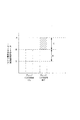
例えば、図10において、モータが像担持体を駆動する駆動トルクが、駆動トルクに略比例する負荷電流値によって例示されている。
ブレードが像担持体に摺接する場合、モータに対してブレードによる負荷がかかる。現像剤が付着していない像担持体にブレードが摺接し、ブレードによる負荷がモータにかかる場合、検知装置によって検知されるモータの負荷電流値(像担持体を駆動する駆動トルクに対応)はAとなっている。一方、ブレードが像担持体に摺接せず、ブレードによる負荷がモータにかからない場合には、モータの負荷電流値はBとなっている。即ち、ブレードが像担持体に摺接すると、モータは、負荷電流値Cに対応する値の駆動トルクが増加する。
For example, in FIG. 10, the driving torque with which the motor drives the image carrier is exemplified by the load current value that is substantially proportional to the driving torque.
When the blade is in sliding contact with the image carrier, a load is applied to the motor by the blade. When the blade is in sliding contact with the image carrier to which the developer is not attached and a load is applied to the motor by the blade, the load current value of the motor detected by the detection device (corresponding to the driving torque for driving the image carrier) is A It has become. On the other hand, the load current value of the motor is B when the blade is not in sliding contact with the image carrier and the load by the blade is not applied to the motor. That is, when the blade is brought into sliding contact with the image carrier, the driving torque of the motor corresponding to the load current value C increases.
負荷電流値Bに対応するモータの駆動トルクには、モータがギアなどの駆動部のみを駆動する場合にかかる負荷電流値Dに対応する駆動トルクが含まれている。負荷電流値Bと負荷電流値Dとの差の負荷電流値Eに対応する駆動トルクには、像担持体の重量による駆動トルク、及び、像担持体の周囲に設けられたシール部材などによる駆動トルクが含まれている。また、例えば負荷電流値C,D,Eは略同じ値になっており、負荷電流値Cに対応する駆動トルクは、検知装置が検知する負荷電流値Aの略3分の1になっている。
このように、上記従来例においては、ブレードの劣化によるトルクの変化を精度よく検知できないために、ブレードによる感光体のクリーニング状態を判定する精度を上げられないという問題があった。
The drive torque of the motor corresponding to the load current value B includes the drive torque corresponding to the load current value D applied when the motor drives only a drive unit such as a gear. The drive torque corresponding to the load current value E, which is the difference between the load current value B and the load current value D, includes a drive torque based on the weight of the image carrier and a drive by a seal member provided around the image carrier. Torque is included. Further, for example, the load current values C, D, and E are substantially the same value, and the driving torque corresponding to the load current value C is approximately one third of the load current value A detected by the detection device. .
As described above, in the above conventional example, a change in torque due to blade deterioration cannot be detected with high accuracy, and thus there is a problem that the accuracy of determining the cleaning state of the photosensitive member by the blade cannot be increased.
そこで、本発明は、像担持体のクリーニング状態を精度よく判定することができる画像形成装置を提供することを目的とする。 SUMMARY An advantage of some aspects of the invention is that it provides an image forming apparatus that can accurately determine the cleaning state of an image carrier.
上記目的を達成するため、本発明の第1の特徴とするところは、現像剤像を担持する像担持体と、この像担持体を駆動する駆動手段と、前記像担持体に担持された現像剤像が転写された後に、前記像担持体上に残留する現像剤をクリーニングするクリーニング手段と、前記駆動手段が前記像担持体を駆動する駆動トルクを検知する検知手段と、前記像担持体上の前記クリーニング手段に到達する現像剤有無時それぞれにおける前記検知手段により検知された駆動トルクの差の履歴を記憶する記憶手段と、前記記憶手段に記憶された前記駆動トルクの差の履歴に基づいて、前記トルクの差の傾向を示す近似式を算出する算出手段と、前記算出手段に算出された近似式に基づいて、前記クリーニング手段の交換時期を予測する予測手段とを有する画像形成装置にある。即ち、像担持体を駆動する駆動トルクに対し、像担持体上の現像剤の有無による影響に基づいて、クリーニング手段の交換時期が予測されるので、像担持体上の現像剤以外の条件変化による駆動手段の駆動トルクへの影響を取り除くことができ、クリーニング手段の交換時期を精度よく予測することができる。したがって、像担持体のクリーニング不良を防止しつつ、不要なクリーニング手段の交換を防ぐことができる。
In order to achieve the above object, the first feature of the present invention is that an image carrier carrying a developer image, driving means for driving the image carrier, and development carried on the image carrier. A cleaning unit that cleans developer remaining on the image carrier after the agent image is transferred; a detection unit that detects a driving torque by which the driving unit drives the image carrier; said storage means for storing a history of the difference between the driving torque detected by said detecting means definitive each time the developer whether it reaches the cleaning means, based on the history of the difference between said stored drive torque to said memory means Te has a calculating means for calculating an approximate expression indicating the tendency of the difference of the torque, based on the approximate expression calculated for the calculation unit, and a prediction means for predicting a replacement time of said cleaning means In an image forming apparatus. That is, since the replacement timing of the cleaning means is predicted based on the influence of the presence or absence of the developer on the image carrier with respect to the driving torque for driving the image carrier, the change in conditions other than the developer on the image carrier by can remove the influence of the driving torque of the driving means, the replacement time of the cleaning means can be predicted accurately. Accordingly, unnecessary cleaning means can be prevented from being replaced while preventing the image carrier from being poorly cleaned.
また、好適には、前記駆動手段は、前記像担持体を回転させるモータと、このモータの回転速度を保持するように制御する回転速度制御手段とを有し、前記検知手段は、前記モータの負荷電流、入力電圧及び消費電力のいずれかにより前記駆動手段の駆動トルクを検知する。したがって、像担持体を回転させるモータのトルクを検知するために、専用のトルクセンサを設ける必要がなく、検知手段の構成を簡易にすることができる。 Preferably, the driving means includes a motor that rotates the image carrier, and a rotation speed control means that controls the motor so as to maintain the rotation speed of the motor, and the detection means includes the motor. The driving torque of the driving means is detected by any one of load current, input voltage and power consumption. Therefore, it is not necessary to provide a dedicated torque sensor in order to detect the torque of the motor that rotates the image carrier, and the configuration of the detection means can be simplified.
本発明によれば、像担持体のクリーニング状態を精度よく判定することができる。 According to the present invention, the cleaning state of the image carrier can be accurately determined.
次に本発明の実施形態を図面に基づいて説明する。
図1において、本発明の実施形態に係る画像形成装置10の概要が示されている。
図1に示すように、画像形成装置10は、ユーザインターフェイス(UI)11、画像読取ユニット12、画像形成ユニット14、中間転写装置16、複数の記録媒体トレイ17、記録媒体搬送路18、定着器19及び制御部20を有する。この画像形成装置10は、画像読取装置12を用いたフルカラー複写機としての機能、及び、ファクシミリとしての機能を兼ね備えた複合機であってもよい。なお、本実施形態では、中間転写装置16を有する画像形成装置10を具体例として説明するが、これに限定されるものではなく、例えば、感光体から中間転写体を用いることなく記録媒体に画像を転写する画像形成装置であってもよい。
Next, embodiments of the present invention will be described with reference to the drawings.
FIG. 1 shows an outline of an image forming apparatus 10 according to an embodiment of the present invention.
As shown in FIG. 1, an image forming apparatus 10 includes a user interface (UI) 11, an image reading unit 12, an image forming unit 14, an intermediate transfer device 16, a plurality of recording medium trays 17, a recording
画像形成装置10は、上部にUI11及び画像読取装置12が配設され、UI11の下方に制御部20が配置されている。UI11は、例えばタッチパネルなどからなり、作業者から画像形成装置10に対する指示を受入れると共に、画像形成装置10に関する情報を表示する。画像読取装置12は、原稿に表示された画像を読み取って、画像データを制御部20に対して出力する。制御部20は、画像形成装置10を動作させるプログラム、及び画像データなどを記憶するメモリ200を有し、画像読取装置12から入力された画像データを取得し、この画像データに対して階調補正及び解像度補正などの画像処理を施し、画像形成ユニット14に対して出力する。また、制御部20は、画像形成装置10を構成する各部を制御する。
In the image forming apparatus 10, the
画像読取装置12の下方には、複数の画像形成ユニット14が配設されている。本例では、イエロー(Y)、マゼンタ(M)、シアン(C)、黒(K)の各色に対応して第1の画像形成ユニット14Y、第2の画像形成ユニット14M、第3の画像形成ユニット14C及び第4の画像形成ユニット14Kが、中間転写装置16に沿って一定の間隔を空けてほぼ水平に配列されている。
中間転写装置16は、例えば中間転写ベルトなどの中間転写体160を回転させ、4つの画像形成ユニット14Y、14M、14C、14Kは、制御部20から入力された画像データに基づいて各色の現像剤像を順次形成し、これら複数の現像剤像が互いに重ね合わせられるタイミングで中間転写体160に転写(一次転写)する。
A plurality of image forming units 14 are disposed below the image reading device 12. In this example, the first
The intermediate transfer device 16 rotates an
記録媒体搬送路18は、中間転写装置16の下方に配設されている。第1の記録媒体トレイ17a又は第2の記録媒体トレイ17bから供給された記録媒体32a又は32bは、この記録媒体搬送路18に沿って搬送され、上記中間転写体160上に多重に転写された各色の現像剤像が一括して転写(二次転写)され、転写された現像剤像が定着器37によって定着され、外部に排出される。
The recording
次に、画像形成装置10の各構成についてより詳細に説明する。
UI11は、例えば画像形成枚数などの指示を作業者から受け入れると共に、後述する像担持体をクリーニングするブレードの交換時期などの画像形成装置10に関する情報を表示する。画像読取ユニット12は、原稿を載せるプラテンガラス122と、この原稿をプラテンガラス122上に押圧するプラテンカバー124と、プラテンガラス122上に載置された原稿の画像を読み取る画像読取装置130とを有する。
Next, each configuration of the image forming apparatus 10 will be described in detail.
The
制御部20は、上述したように画像形成装置10を構成する各部を制御し、画像読取ユニット12により読み取られた画像データに対して所定の画像処理を施すとともに、例えば各画像形成ユニット14Y、14M、14C、14K及び中間転写装置16のクリーニング状況を管理する。例えば制御部20は、画像形成ユニット14の後述するブレード158の交換時期などを予測して、UI11に予測結果を表示する。また、制御部20のメモリ200は、後述する検知装置156から入力される負荷電流値などを含むデータ、及び、各画像形成ユニット14Y、14M、14C、14K及び中間転写装置16のメンテナンス時期又は交換時期などを予測する予測プログラムを含むプログラムを記憶する。
The
中間転写装置16は、ドライブロール164、第1のアイドルロール165、ステアリングロール166、第2のアイドルロール167、バックアップロール168、及び第3のアイドルロール169の間に一定のテンションで掛け回された中間転写体160を有し、駆動モータ(図示せず)によってドライブロール164が回転駆動されることにより、所定の速度でこの中間転写体160を循環駆動する。中間転写体160は、例えば、可撓性を有するポリイミド等の合成樹脂フィルムを帯状に形成し、この帯状に形成された合成樹脂フィルムの両端を溶着等によって接続することにより無端ベルト状に形成されたものである。また、中間転写装置16は、各画像形成ユニット14Y、14M、14C、14Kに対向する位置にそれぞれ第1の一次転写ロール162Y、第2の一次転写ロール162M、第3の一次転写ロール162C及び第4の一次転写ロール162Kを有し、像担持体152Y、152M、152C、152K上に形成された各色の現像剤像を、これらの一次転写ロール162により中間転写体160上に多重転写する。
また、中間転写体160の二次転写位置下流には、ブレード161が設けられている。ブレード161は、制御部20の制御により所定のタイミングで中間転写体160に摺接し、中間転写体160が記録媒体に現像剤像を転写した後に、中間転写体160上に付着した残留現像剤及び放電生成物などを掻き取って廃現像剤ボックスに回収する。
The intermediate transfer device 16 is wound around the
A
記録媒体搬送路18には、第1の記録媒体トレイ17a又は第2の記録媒体トレイ17bから第1の記録媒体32a又は第2の記録媒体32bを取り出す第1の供給ロール181a及び第2の供給ロール181bと、記録媒体搬送用のロール対182と、記録媒体32a及び32bを所定のタイミングで二次転写位置に搬送するレジストロール183とが配設される。
また、記録媒体搬送路18上の二次転写位置には、バックアップロール168に中間転写体160を介して圧接する二次転写ロール185が配設されており、中間転写体160上に多重に転写された各色の現像剤像は、この二次転写ロール185による圧接力及び静電気力で記録媒体32a又は32b上に二次転写される。各色の現像剤像が転写された記録媒体32a又は32bは、2つの搬送ベルト186によって定着器19へと搬送される。
The recording
In addition, a
定着器19は、上記各色の現像剤像が転写された記録媒体32a又は32bに対して加熱処理及び加圧処理を施すことにより、現像剤を記録媒体32a又は32bに溶融固着させる。
定着器19により定着処理(加熱及び加圧)が施された記録媒体32a又は32bは、定着器19の後段に設けられた排出経路187(搬送路)を通って、画像形成装置10の外部に排出され、排出トレイに積載される。また、排出経路187には、測色センサ189が設けられている。測色センサ189は、例えば、色彩計又は濃度計などであり、記録媒体32a又は32b上の画像を読み取り、この画像の特徴量を検知する。
The fixing device 19 melts and fixes the developer to the
The
第1の画像形成ユニット14Y、第2の画像形成ユニット14M、第3の画像形成ユニット14C及び第4の画像形成ユニット14Kは、ほぼ水平方向に一定の間隔をおいて配置され、形成する画像の色が異なる他は、ほぼ同様に構成されている。そこで、以下、第1の画像形成ユニット14Yについて説明する。なお、各画像形成ユニット14のいずれかを特定する場合には、Y、M、C又はKを付すことにより区別する。
The first
図2において、画像形成ユニット14Yの詳細が示されている。
画像形成ユニット14Yは、制御部20から入力された画像データに応じてレーザ光を走査する光走査装置140Yと、この光走査装置140Yにより走査されたレーザ光により静電潜像が形成される像形成装置150Yとを有する。
FIG. 2 shows details of the
The
光走査装置140Yは、半導体レーザ142Yをイエロー(Y)の画像データに応じて変調して、この半導体レーザ142Yからレーザ光LB(Y)を画像データに応じて出射する。この半導体レーザ142Yから出射されたレーザ光LB(Y)は、第1の反射ミラー143Y及び第2の反射ミラー144Yを介して回転多面鏡146Yに照射され、この回転多面鏡146Yによって偏向走査され、第2の反射ミラー144Y、第3の反射ミラー148Y及び第4の反射ミラー149Yを介して、像形成装置150Yの後述する像担持体152Y上に照射される。
The
像形成装置150Yは、像担持体151Y、モータ152Y、帯電装置153Y、現像器154Y、クリーニング装置155Y及び検知装置156Yを有する。像担持体151Yは、例えば感光体ドラムからなり、モータ152Yにより駆動されて回転する。モータ152Yは、例えば直流モータであり、制御部20の電流制御によって所定の回転速度で回転し、像担持体151Yを略一定の回転速度で回転させる。帯電装置153Yは、例えばスコロトロンであり、像担持体151Yの表面を一様に帯電する。現像器154Yは、現像ロール157Yを有し、この現像ロール157Yが現像器154Y内の現像剤により像担持体151Yの表面に形成された静電潜像を現像する。
The
クリーニング装置155Yは、例えば板状のブレード158Yを有し、このブレード158Yが像担持体151Yに摺接し、像担持体151Yに担持された現像剤像が中間転写体160に転写された後に、像担持体151Y上に付着した残留現像剤及び放電生成物などを掻き取って、クリーニング装置155Y内に回収する。検知装置156Yは、例えば電流計であり、制御部20の制御により、像担持体151Yとブレード158Yの摺擦部に現像剤がある状態及びない状態の両方の状態におけるモータ152Yの負荷電流を所定の間隔で定期的に検知し、それぞれの負荷電流値を制御部20に対して出力する。例えば、検知装置156Yは、像担持体151Yが所定回数の回転をすると、像担持体151Y上に現像剤がある状態及びない状態の両方の状態におけるモータ152Yの負荷電流を検知する。
The
なお、像担持体151Y上に現像剤がある状態及びない状態は、例えば像担持体151Y上の所定の位置のみに現像剤を付着させた所謂現像剤バンド(図3参照)によって生じさせられる。また、検知装置156Yが検知する負荷電流は、モータ152Yが像担持体151Yを駆動する駆動トルクに略比例している。つまり、制御部20は、検知装置156Yが検知した負荷電流値を受入れて、所定の係数演算を行い、モータ152Yが像担持体151Yを駆動する駆動トルクを検知するようにされている。
The state where the developer is present on the
このように、像担持体151Yは、モータ152Yにより略一定の回転速度で回転し、帯電装置153Yにより一様に帯電され、光走査装置140Yにより照射されたレーザ光LB(Y)により静電潜像を形成される。像担持体151Yに形成された静電潜像は、現像器154Yによりイエロー(Y)の現像剤で現像される。検知装置156Yが所定の間隔で像担持体151Y上のブレード158Yとの摺擦部に現像剤がある状態及びない状態の両方の状態に対してモータ152Yの負荷電流を検知することにより、制御部20は、モータ152Yが像担持体151Yを駆動する駆動トルクをそれぞれの状態に対して検知し、ブレード158Yの交換時期を後述する交換時期予測プログラム4を用いて予測する。
In this manner, the
他の画像形成ユニット14M、14C及び14Kも、上記画像形成ユニット14Yと同様に、マゼンタ(M)、シアン(C)、黒(K)の各色の現像剤像を形成し、形成された各色の現像剤像を中間転写装置16に転写する。また、画像形成ユニット14M、14C及び14Kは、それぞれの像担持体上に現像剤がある状態及びない状態の両方の状態におけるモータの負荷電流を検知装置によって検知し、負荷電流値を制御部20に対して出力する。制御部20は、画像形成ユニット14Y、14M、14C及び14Kそれぞれの像担持体を駆動する駆動トルクを像担持体上に現像剤がある状態及びない状態の両方の状態に対して検知し、ブレード158Yの交換時期を予測する。
なお、制御部20のメモリ200(図1)は、負荷電流値C(図10)に対応する値の駆動トルクを、ブレード158Yが像担持体151Yに摺接することによる駆動トルクとして記憶するようにされているとより好ましい。
The other
Note that the memory 200 (FIG. 1) of the
図3において、像担持体151Y上に形成された現像剤バンドの例が示されている。
現像剤バンドは、例えば像担持体151Yの回転方向に対し、略直角方向に所定の幅で現像剤が付着されて形成される。即ち、現像剤バンドにより、像担持体151Y上のブレード158Yとの摺擦部に現像剤がある状態及びない状態がつくられ、検知装置156Yは、制御部20の制御により、像担持体151Y上に現像剤がある状態及びない状態の両方の状態におけるモータ152Yの負荷電流を検知することができる。また、現像剤バンドは、像担持体151Y上の略同じ位置に、所定の間隔で定期的に形成されるようになっている。よって、検知装置156Yは、像担持体151Yの回転にぶれが生じても、像担持体151Yの回転ぶれによる負荷電流値の変化を防止して、モータ152Yの負荷電流を検知することができる。
なお、像担持体151Y上のブレード158Yとの摺擦部に現像剤がある状態及びない状態の両方の状態に対し、モータ152Yの負荷電流を検知装置156Yが検知するために、像担持体151Yの略表面全体に現像剤を付着させてモータ152Yの負荷電流を検知した後に、像担持体151Y上の現像剤を除去してモータ152Yの負荷電流を検知するようにしてもよい。この場合には、それぞれの状態における像担持体151Yの回転方向1周分の負荷電流の平均値を負荷電流値としてもよい。
FIG. 3 shows an example of a developer band formed on the
The developer band is formed, for example, by attaching a developer with a predetermined width in a direction substantially perpendicular to the rotation direction of the
It should be noted that the
図4は、像担持体151Yのクリーニング状況が良好な状態において、図3に示した現像剤バンドに対し、検知装置156Yを介して制御部20が検知したモータ152Yの駆動トルクが例示されている。なお、図4に示した駆動トルクは、ブレード158Yが像担持体151Yに摺接することによる負荷電流値A(図10)でもよいが、より好ましくは負荷電流値Cに対応する値の駆動トルクであり、像担持体151Y上のブレード158Yとの摺擦部に現像剤がある状態では、ブレード158Yが像担持体151Y上の現像剤を掻き取るので、像担持体151Y上のブレード158Yとの摺擦部に現像剤がない状態に対して駆動トルクの値が高くなっている。このトルクの差がトナーを掻き取るために使用されるエネルギーと考えられる。この場合、像担持体151Y上に現像剤がない状態に対する像担持体151Y上に現像剤がある状態のトルク差Fは、正の値になっている。即ち、像担持体151Y上に現像剤がない状態に対する現像剤がある状態の駆動トルクの比は、1より大きくなっている。
FIG. 4 illustrates the driving torque of the
図5は、画像形成装置10が継続的に動作し、像担持体151Y上のブレード158Yとの摺擦部に現像剤がある状態及びない状態で定期的に検知されたモータ152Yの駆動トルクの実験結果を示すグラフであって、(A)は像担持体151Yのクリーニング状況が良好な状態を示し、(B)は像担持体151Yのクリーニング状況が悪化している状態を示すグラフである。なお、図5に示した実験結果においては、現像剤バンドが定期的に形成され、時間に比例して像担持体151Yが回転するようにされている。
FIG. 5 shows the driving torque of the
像担持体151Yのクリーニング状況が良好な状態において、像担持体151Y上のブレード158Yとの摺擦部に現像剤がある状態には、ブレード158Yが像担持体151Y上の現像剤を掻き取るので、像担持体151Y上のブレード158Yとの摺擦部に現像剤がない状態に対するトルク差Fが所定の値よりも大きくなっている。即ち、トルク差Fの累積値は増加する。
一方、像担持体151Yのクリーニング状況が悪化している状態では、像担持体151Y上のブレード158Yとの摺擦部に現像剤がある状態と、像担持体151Y上のブレード158Yとの摺擦部に現像剤がない状態との間に生じるトルク差Fが小さくなり、トルク差Fの累積値は、像担持体151Yのクリーニング状況が良好な状態に対して小さい。また、像担持体151Yのクリーニング状況がさらに悪化すると、像担持体151Y上のブレード158Yとの摺擦部に現像剤がない状態のモータ152Yの駆動トルクよりも、像担持体151Y上のブレード158Yとの摺擦部に現像剤がある状態のモータ152Yの駆動トルクが小さくなる。このように、像担持体151Yのクリーニング状況が悪化している状態において、像担持体151Y上のブレード158Yとの摺擦部に現像剤がある状態の駆動トルクが小さくなるのは、劣化したブレード158Yと像担持体151Yとの間を現像剤がすり抜け、このすり抜けた現像剤がコロの役目を果たすためと推定される。
In a state where the
On the other hand, in a state where the cleaning state of the
図6は、像担持体151Yが回転した回数に対し、像担持体151Y上のブレード158Yとの摺擦部に現像剤がある状態と、像担持体151Y上のブレード158Yとの摺擦部に現像剤がない状態との間に生じるトルク差Fの変化を例示するグラフである。なお、画像形成装置10の使用条件Iと使用条件Jとは、例えば湿度などの条件が異なり、使用条件Iは、使用条件Jよりも像担持体151Yに現像剤が付着しやすい条件になっている。
FIG. 6 shows a state in which there is a developer in the rubbing portion with the
画像形成装置10の動作開始時(初期状態)において、像担持体151Y上のブレード158Yとの摺擦部に現像剤がない状態に対し、像担持体151Y上のブレード158Yとの摺擦部に現像剤がある状態は、モータ152Yの駆動トルクが大きくなっている。像担持体151Yが回転した回数が多くなると、ブレード158Yは、像担持体151Yに摺接することにより摩耗し、像担持体151Yのクリーニング状況が悪化してくる。像担持体151Yは、継続して使用されると、摩耗などにより劣化し、像担持体151Y上のブレード158Yとの摺擦部に現像剤がある状態と、像担持体151Y上のブレード158Yとの摺擦部に現像剤がない状態との間に生じるトルク差Fが減少し続け、トルク差Fが0、又は負の値になる。
When the operation of the image forming apparatus 10 is started (initial state), the developer is not in the rubbing portion with the
例えば、像担持体151Yのクリーニング状況が悪化し、トルク差Fが0になった場合がブレード158Yの交換時期である。つまり、画像形成装置10の使用条件Jにおいては、像担持体151Yのクリーニング状況が使用条件Iに対して悪化しにくく、ブレード158Yの交換が必要な時期は、使用条件Iに対して遅くなっている。
そこで、像担持体151Yが回転した回数に対し、トルク差Fが減少する傾向を用いて、トルク差Fが0になる以前にブレード158Yの交換時期(寿命)を予測する。つまり、ブレード158Yが劣化して像担持体151Yをクリーニングできなくなる以前に、ブレード158Yが交換されることを防止する。
For example, when the cleaning state of the
Therefore, the replacement time (life) of the
図7において、図1に示した制御部20により実行され、ブレード158Yの交換時期を予測する交換時期予測プログラム4の構成が示されている。図7に示すように、交換時期予測プログラム4は、トルク差算出部40、カウンタ41、データ形成部42、履歴データベース(履歴DB)43、近似式算出部44、交換時期算出部46、判定部47及び表示処理部48から構成される。
7 shows the configuration of the replacement time prediction program 4 that is executed by the
トルク差算出部40は、検知装置156Yが検知した像担持体151Y上に現像剤がある状態の負荷電流値と、像担持体151Y上に現像剤がない状態の負荷電流値とを受け入れ、それぞれの負荷電流値に対応する駆動トルク、及び、それぞれの駆動トルクから現在のトルク差Fを算出し、データ形成部42及び近似式算出部44に対して出力する。
The torque difference calculation unit 40 receives the load current value in the state where the developer is present on the
カウンタ41は、像担持体151Yが回転した回数をカウントし、データ形成部42に対して出力する。
データ形成部42は、現在のトルク差Fをトルク差算出部40から受け入れ、像担持体151Yが回転した回数をカウンタ41から受入れて、現在のトルク差Fと像担持体151Yが回転した回数とを組合わせたデータを形成し、履歴データベース43に対して出力する。
The counter 41 counts the number of rotations of the image carrier 151 </ b> Y and outputs it to the data forming unit 42.
The data forming unit 42 receives the current torque difference F from the torque difference calculating unit 40, receives the number of rotations of the
履歴データベース43は、データ形成部42から入力されたトルク差Fと像担持体151Yが回転した回数とを組合わせたデータを継続的に格納して、像担持体151Yが回転した回数に対するトルク差Fの履歴を示すデータベースを形成し、近似式算出部44のアクセスにより、近似式算出部44に対して出力する。
The history database 43 continuously stores data obtained by combining the torque difference F input from the data forming unit 42 and the number of rotations of the
近似式算出部44は、履歴データベース43に対してアクセスし、像担持体151Yが回転した回数に対するトルク差Fの履歴を示すデータベースを受け入れ、現在のトルク差Fをトルク差算出部40から受け入れて、トルク差Fの変化の傾向を示す近似式を算出し、交換時期算出部46に対して出力する。トルク差Fの変化の傾向を示す近似式は、多次の近似式であってもよいし、1次の近似式であってもよい。
The approximate expression calculation unit 44 accesses the history database 43, receives a database indicating the history of the torque difference F with respect to the number of rotations of the
交換時期算出部46は、近似式算出部44から入力されたトルク差Fの変化の傾向を示す近似式により、トルク差Fが0になるまでに像担持体151Yが回転可能な回数(ブレード158Yの寿命)を算出し、判定部47に対して出力する。
The replacement time calculation unit 46 calculates the number of times the
判定部47は、交換時期算出部46からトルク差Fが0以下になるまでに像担持体151Yが回転可能な回数を受け入れ、トルク差Fが0以下になるまでに像担持体151Yが回転可能な回数が0(交換時期)であるか否かを判定し、判定結果を表示処理部48に対して出力する。
表示処理部48は、判定部47から入力された判定結果により、トルク差Fが0以下になるまでに像担持体151Yが回転可能な回数が0の場合には、ブレード158Yの交換指示を示す信号をUI11に対して出力し、その他の場合には、ブレード158Yの交換時期(又はブレード158Yの寿命)を示す信号をUI11に対して出力する。
The determination unit 47 receives the number of times that the
The display processing unit 48 indicates an instruction to replace the
次に画像形成装置10がブレード158Yの交換時期を予測する動作について説明する。
図8は、図7に示した交換時期予測プログラム4を用いて、画像形成装置10がブレード158Yの交換時期を予測する処理(S10)を示すフローチャートである。図9は、図7に示した交換時期予測プログラム4の処理(S20)を示すフローチャートである。
図8に示すように、ステップ100(S100)において、画像形成装置10は、制御部20の制御によって、図3に示した現像剤バンドを像担持体151Y上に形成し、S102の処理に進む。
Next, an operation in which the image forming apparatus 10 predicts the replacement time of the
FIG. 8 is a flowchart showing a process (S10) in which the image forming apparatus 10 predicts the replacement time of the
As shown in FIG. 8, in step 100 (S100), the image forming apparatus 10 forms the developer band shown in FIG. 3 on the
ステップ102(S102)において、検知装置156Yは、像担持体151Yを駆動するモータ152Yに対し、像担持体151Y上に現像剤がある状態の負荷電流、及び、像担持体151Y上に現像剤がない状態の負荷電流を検知して、それぞれの負荷電流値を制御部20に対して出力し、S20(図9)の処理にすすむ。
In step 102 (S102), the
ステップ200(S200:図9)において、トルク差算出部40は、検知装置156Yから入力される像担持体151Y上に現像剤がある状態の負荷電流値、及び、像担持体151Y上に現像剤がない状態の負荷電流値を受け入れ、それぞれの負荷電流値に対応する駆動トルク、及び、それぞれの駆動トルクから現在のトルク差Fを算出する。トルク差算出部40は、算出したトルク差Fをデータ形成部42及び近似式算出部44に対して出力し、S202の処理に進む。
In step 200 (S200: FIG. 9), the torque difference calculation unit 40 inputs the load current value in a state where there is a developer on the
ステップ202(S202)において、データ形成部42は、現在のトルク差Fをトルク差算出部40から受け入れ、像担持体151Yが回転した回数ををカウンタ41から受入れて、現在のトルク差Fと像担持体151Yが回転した回数とを組合わせたデータを形成し、S204の処理に進む。
In step 202 (S202), the data forming unit 42 receives the current torque difference F from the torque difference calculating unit 40, receives the number of rotations of the
ステップ204(S204)において、履歴データベース43は、データ形成部42から入力されたトルク差Fと像担持体151Yが回転した回数とを組合わせたデータを継続的に格納し、S206の処理に進む。
In step 204 (S204), the history database 43 continuously stores data combining the torque difference F input from the data forming unit 42 and the number of rotations of the
ステップ206(S206)において、近似式算出部44は、像担持体151Yが回転した回数に対するトルク差Fの履歴を示すデータベースを受け入れ、現在のトルク差Fをトルク差算出部40から受け入れて、トルク差Fの変化の傾向を示す近似式を算出し、S208の処理に進む。
In step 206 (S206), the approximate expression calculation unit 44 receives a database indicating the history of the torque difference F with respect to the number of rotations of the
ステップ208(S208)において、交換時期算出部46は、近似式算出部44から入力されたトルク差Fの変化の傾向を示す近似式により、トルク差Fが0になるまでに像担持体151Yが回転可能な回数を算出し、S210の処理に進む。
In step 208 (S208), the replacement timing calculation unit 46 determines that the
ステップ210(S210)において、判定部47は、交換時期算出部46からトルク差Fが0以下になるまでに像担持体151Yが回転可能な回数を受け入れ、トルク差Fが0以下になるまでに像担持体151Yが回転可能な回数が0であるか否かを判定する。トルク差Fが0以下になるまでに像担持体151Yが回転可能な回数が0の場合にはS212の処理に進み、その他の場合にはS214の処理に進む。
In step 210 (S210), the determination unit 47 receives the number of rotations of the
ステップ212(S212)において、表示処理部48は、UI11を介してブレード158Yの交換指示を表示し、S104(図8)の処理に進む。
In step 212 (S212), the display processing unit 48 displays an instruction to replace the
ステップ214(S214)において、表示処理部48は、UI11を介してブレード158Yの交換時期を表示し、S104(図8)の処理に進む。
In step 214 (S214), the display processing unit 48 displays the replacement time of the
ステップ104(S104:図8)において、ブレード158Yが像担持体151Yに形成された現像剤バンドをクリーニングし、画像形成装置10は現在におけるブレード158Yの交換時期を予測する処理を終了する。
In step 104 (S104: FIG. 8), the
また、画像形成装置10は、他の画像形成ユニット14M、14C、14Kのブレードについても同様に、交換時期を予測するようにされている。
Similarly, the image forming apparatus 10 predicts the replacement time for the blades of the other
なお、上記実施形態においては、像担持体151Yが回転した回数に対するモータ152Yのトルク差Fの変化によってブレード158Yの交換時期を予測しているが、これに限定されることなく、例えば画像形成した記録媒体の枚数に対するトルク差Fの変化によってブレード158Yの交換時期を予測してもよい。検知装置156Yが検知する値は、像担持体151Yを駆動するモータの種類に応じて、モータに加えられる電圧又は電力などを検知するようにしてもよい。
また、画像形成装置10は、モータ152Yのトルク差Fの変化により、像担持体151Yをクリーニングする時期、又は、像担持体151Yの交換時期を予測するようにしてもよい。
In the above embodiment, the replacement time of the
Further, the image forming apparatus 10 may predict the time for cleaning the
また、中間転写体160上に現像剤バンドを形成し、中間転写体160上に現像剤がある状態のドライブロール164の負荷電流、及び、中間転写体160上に現像剤がない状態のドライブロール164の負荷電流を検知し、ブレード161の交換時期を予測するようにしてもよい。
Further, a developer band is formed on the
画像形成装置10においては、ブレードの交換時期を予測するため以外にも、現像剤濃度の調整などのために像担持体に現像剤バンドが形成される。例えば、像担持体に形成された現像剤バンドの現像剤濃度をセンサによって検知して現像剤濃度を調整する場合、及び、現像器154Y内で長時間攪拌された現像剤を消費することにより現像剤濃度を調整する場合などに現像剤バンドが形成される。このような場合に形成された現像剤バンドに対し、像担持体上に現像剤がある状態のモータの負荷電流、及び像担持体上に現像剤がない状態のモータの負荷電流を検知して、現像剤の無駄な消費をなくすようにしてもよい。
In the image forming apparatus 10, a developer band is formed on the image carrier not only for predicting the blade replacement time but also for adjusting the developer concentration. For example, when the developer density of the developer band formed on the image carrier is detected by a sensor to adjust the developer density, and development is performed by consuming the developer stirred for a long time in the developing
10 画像形成装置
12 画像読取ユニット
14 画像形成ユニット
140 光走査装置
150 像形成装置
151 像担持体
152 モータ
153 帯電装置
154 現像器
155 クリーニング装置
156 検知装置
157 現像ロール
158 ブレード
160 中間転写体
161 ブレード
164 ドライブロール
18 記録媒体搬送路
19 定着装置
20 制御部
200 メモリ
4 交換時期予測プログラム
40 トルク差算出部
41 カウンタ
42 データ形成部
43 履歴データベース
44 近似式算出部
46 交換時期算出部
47 判定部
48 表示処理部
DESCRIPTION OF SYMBOLS 10 Image forming apparatus 12 Image reading unit 14
Claims (2)
この像担持体を駆動する駆動手段と、
前記像担持体に担持された現像剤像が転写された後に、前記像担持体上に残留する現像剤をクリーニングするクリーニング手段と、
前記駆動手段が前記像担持体を駆動する駆動トルクを検知する検知手段と、
前記像担持体上の前記クリーニング手段に到達する現像剤有無時それぞれにおける前記検知手段により検知された駆動トルクの差の履歴を記憶する記憶手段と、
前記記憶手段に記憶された前記駆動トルクの差の履歴に基づいて、前記トルクの差の傾向を示す近似式を算出する算出手段と、
前記算出手段に算出された近似式に基づいて、前記クリーニング手段の交換時期を予測する予測手段と
を有することを特徴とする画像形成装置。 An image carrier for carrying a developer image;
Driving means for driving the image carrier;
Cleaning means for cleaning the developer remaining on the image carrier after the developer image carried on the image carrier is transferred;
Detecting means for detecting a driving torque by which the driving means drives the image carrier;
Storage means for storing a history of differences in driving torque detected by the detection means when there is a developer reaching the cleaning means on the image carrier;
Calculation means for calculating an approximate expression indicating a tendency of the difference in torque based on a history of the difference in driving torque stored in the storage means;
An image forming apparatus comprising: a predicting unit that predicts a replacement time of the cleaning unit based on the approximate expression calculated by the calculating unit.
前記検知手段は、前記モータの負荷電流、入力電圧及び消費電力のいずれかにより前記駆動手段の駆動トルクを検知することを特徴とする請求項1記載の画像形成装置。 The drive means includes a motor for rotating the image carrier, and a rotation speed control means for controlling the motor to maintain the rotation speed thereof.
The image forming apparatus according to claim 1, wherein the detection unit detects a driving torque of the driving unit based on any one of a load current, an input voltage, and power consumption of the motor.
Priority Applications (1)
| Application Number | Priority Date | Filing Date | Title |
|---|---|---|---|
| JP2004007671A JP4561959B2 (en) | 2004-01-15 | 2004-01-15 | Image forming apparatus |
Applications Claiming Priority (1)
| Application Number | Priority Date | Filing Date | Title |
|---|---|---|---|
| JP2004007671A JP4561959B2 (en) | 2004-01-15 | 2004-01-15 | Image forming apparatus |
Publications (2)
| Publication Number | Publication Date |
|---|---|
| JP2005202099A JP2005202099A (en) | 2005-07-28 |
| JP4561959B2 true JP4561959B2 (en) | 2010-10-13 |
Family
ID=34821234
Family Applications (1)
| Application Number | Title | Priority Date | Filing Date |
|---|---|---|---|
| JP2004007671A Expired - Fee Related JP4561959B2 (en) | 2004-01-15 | 2004-01-15 | Image forming apparatus |
Country Status (1)
| Country | Link |
|---|---|
| JP (1) | JP4561959B2 (en) |
Families Citing this family (8)
| Publication number | Priority date | Publication date | Assignee | Title |
|---|---|---|---|---|
| JP4360384B2 (en) | 2006-06-30 | 2009-11-11 | ブラザー工業株式会社 | Image forming apparatus |
| JP5171217B2 (en) * | 2007-11-12 | 2013-03-27 | キヤノン株式会社 | Image forming apparatus |
| JP6335664B2 (en) * | 2014-06-09 | 2018-05-30 | キヤノン株式会社 | Image forming apparatus |
| JP6142857B2 (en) * | 2014-09-29 | 2017-06-07 | ブラザー工業株式会社 | Image forming apparatus, image forming apparatus control method, and image forming apparatus control program |
| JP6465697B2 (en) * | 2015-03-02 | 2019-02-06 | キヤノン株式会社 | Image forming apparatus |
| JP6748500B2 (en) * | 2016-07-13 | 2020-09-02 | キヤノン株式会社 | Image forming device |
| JP7047601B2 (en) * | 2018-05-31 | 2022-04-05 | コニカミノルタ株式会社 | Image forming apparatus and control method of image forming apparatus |
| JP7167636B2 (en) * | 2018-11-06 | 2022-11-09 | コニカミノルタ株式会社 | IMAGE FORMING APPARATUS AND CLEANING MEMBER LIFE PREDICTION METHOD |
Citations (3)
| Publication number | Priority date | Publication date | Assignee | Title |
|---|---|---|---|---|
| JPH0660862U (en) * | 1993-01-29 | 1994-08-23 | シャープ株式会社 | Cleaning device |
| JP2002031994A (en) * | 2000-07-18 | 2002-01-31 | Konica Corp | Cleaning device, method for forming image by using that cleaning device and device for image formation |
| JP2004279858A (en) * | 2003-03-18 | 2004-10-07 | Minolta Co Ltd | Image forming apparatus |
Family Cites Families (1)
| Publication number | Priority date | Publication date | Assignee | Title |
|---|---|---|---|---|
| JPH11352852A (en) * | 1998-06-09 | 1999-12-24 | Canon Inc | Image forming device |
-
2004
- 2004-01-15 JP JP2004007671A patent/JP4561959B2/en not_active Expired - Fee Related
Patent Citations (3)
| Publication number | Priority date | Publication date | Assignee | Title |
|---|---|---|---|---|
| JPH0660862U (en) * | 1993-01-29 | 1994-08-23 | シャープ株式会社 | Cleaning device |
| JP2002031994A (en) * | 2000-07-18 | 2002-01-31 | Konica Corp | Cleaning device, method for forming image by using that cleaning device and device for image formation |
| JP2004279858A (en) * | 2003-03-18 | 2004-10-07 | Minolta Co Ltd | Image forming apparatus |
Also Published As
| Publication number | Publication date |
|---|---|
| JP2005202099A (en) | 2005-07-28 |
Similar Documents
| Publication | Publication Date | Title |
|---|---|---|
| JP4981265B2 (en) | Image forming apparatus | |
| JP5256873B2 (en) | Image forming apparatus and image forming method | |
| JP4946061B2 (en) | Image forming apparatus | |
| JP4921035B2 (en) | Image forming apparatus | |
| JP4561959B2 (en) | Image forming apparatus | |
| JP4564769B2 (en) | Image forming apparatus | |
| JP6554775B2 (en) | Image forming apparatus | |
| US8041238B2 (en) | Image forming apparatus, image forming method, and computer program product | |
| JP2008020818A (en) | Image forming apparatus and image stabilization method | |
| JP2007328175A (en) | Image forming apparatus | |
| JP5171217B2 (en) | Image forming apparatus | |
| JP2008299009A (en) | Image forming apparatus | |
| JP4600802B2 (en) | Image forming apparatus | |
| JP2011102851A (en) | Image forming apparatus and processing program | |
| JP2016009161A (en) | Belt driving device, image forming apparatus including belt driving device, and belt conveyor | |
| JP4948100B2 (en) | Toner consumption prediction amount calculation method, toner consumption prediction amount calculation device, and image forming apparatus | |
| JP2005208207A (en) | Image forming apparatus, and method for measuring cleaning state thereof and cleaning method therefor | |
| US7991331B2 (en) | Developing unit, visualized image formation unit and image forming apparatus | |
| JP2005202110A (en) | Image forming apparatus | |
| JP5445955B2 (en) | Image forming apparatus | |
| JP2005181974A (en) | Image forming apparatus | |
| JP2019159056A (en) | Image forming apparatus | |
| JP2012037830A (en) | Image forming apparatus, image forming system and process program | |
| JP5652162B2 (en) | Image forming apparatus | |
| JP7367452B2 (en) | Image forming device and method of controlling the image forming device |
Legal Events
| Date | Code | Title | Description |
|---|---|---|---|
| A621 | Written request for application examination |
Free format text: JAPANESE INTERMEDIATE CODE: A621 Effective date: 20061220 |
|
| A977 | Report on retrieval |
Free format text: JAPANESE INTERMEDIATE CODE: A971007 Effective date: 20091021 |
|
| A131 | Notification of reasons for refusal |
Free format text: JAPANESE INTERMEDIATE CODE: A131 Effective date: 20091027 |
|
| A521 | Written amendment |
Free format text: JAPANESE INTERMEDIATE CODE: A523 Effective date: 20091224 |
|
| A131 | Notification of reasons for refusal |
Free format text: JAPANESE INTERMEDIATE CODE: A131 Effective date: 20100225 |
|
| A521 | Written amendment |
Free format text: JAPANESE INTERMEDIATE CODE: A523 Effective date: 20100421 |
|
| TRDD | Decision of grant or rejection written | ||
| A01 | Written decision to grant a patent or to grant a registration (utility model) |
Free format text: JAPANESE INTERMEDIATE CODE: A01 Effective date: 20100707 |
|
| A01 | Written decision to grant a patent or to grant a registration (utility model) |
Free format text: JAPANESE INTERMEDIATE CODE: A01 |
|
| FPAY | Renewal fee payment (event date is renewal date of database) |
Free format text: PAYMENT UNTIL: 20130806 Year of fee payment: 3 |
|
| R150 | Certificate of patent or registration of utility model |
Ref document number: 4561959 Country of ref document: JP Free format text: JAPANESE INTERMEDIATE CODE: R150 Free format text: JAPANESE INTERMEDIATE CODE: R150 |
|
| A61 | First payment of annual fees (during grant procedure) |
Free format text: JAPANESE INTERMEDIATE CODE: A61 Effective date: 20100720 |
|
| LAPS | Cancellation because of no payment of annual fees |