JP4547239B2 - Engine measuring device - Google Patents
Engine measuring device Download PDFInfo
- Publication number
- JP4547239B2 JP4547239B2 JP2004332471A JP2004332471A JP4547239B2 JP 4547239 B2 JP4547239 B2 JP 4547239B2 JP 2004332471 A JP2004332471 A JP 2004332471A JP 2004332471 A JP2004332471 A JP 2004332471A JP 4547239 B2 JP4547239 B2 JP 4547239B2
- Authority
- JP
- Japan
- Prior art keywords
- engine
- torque
- data
- rotational speed
- control unit
- Prior art date
- Legal status (The legal status is an assumption and is not a legal conclusion. Google has not performed a legal analysis and makes no representation as to the accuracy of the status listed.)
- Expired - Fee Related
Links
- 238000012360 testing method Methods 0.000 claims description 72
- 238000005259 measurement Methods 0.000 claims description 69
- 238000011156 evaluation Methods 0.000 claims description 37
- 230000001052 transient effect Effects 0.000 claims description 34
- 238000012937 correction Methods 0.000 claims description 31
- 238000012545 processing Methods 0.000 claims description 16
- 230000005540 biological transmission Effects 0.000 claims description 15
- 230000003247 decreasing effect Effects 0.000 claims description 4
- 238000004364 calculation method Methods 0.000 description 38
- 239000000446 fuel Substances 0.000 description 9
- 230000008859 change Effects 0.000 description 8
- 238000000034 method Methods 0.000 description 6
- 238000002347 injection Methods 0.000 description 5
- 239000007924 injection Substances 0.000 description 5
- 230000004069 differentiation Effects 0.000 description 3
- 230000007423 decrease Effects 0.000 description 2
- 238000010586 diagram Methods 0.000 description 2
- 230000006870 function Effects 0.000 description 2
- 239000000203 mixture Substances 0.000 description 2
- 238000012986 modification Methods 0.000 description 2
- 230000004048 modification Effects 0.000 description 2
- 230000033228 biological regulation Effects 0.000 description 1
- 230000000694 effects Effects 0.000 description 1
- 239000000284 extract Substances 0.000 description 1
- 230000008569 process Effects 0.000 description 1
- 238000012552 review Methods 0.000 description 1
- 238000004904 shortening Methods 0.000 description 1
- 239000000725 suspension Substances 0.000 description 1
- 230000001360 synchronised effect Effects 0.000 description 1
- 230000007704 transition Effects 0.000 description 1
- 238000010200 validation analysis Methods 0.000 description 1
Images


Classifications
-
- G—PHYSICS
- G01—MEASURING; TESTING
- G01M—TESTING STATIC OR DYNAMIC BALANCE OF MACHINES OR STRUCTURES; TESTING OF STRUCTURES OR APPARATUS, NOT OTHERWISE PROVIDED FOR
- G01M15/00—Testing of engines
- G01M15/04—Testing internal-combustion engines
- G01M15/042—Testing internal-combustion engines by monitoring a single specific parameter not covered by groups G01M15/06 - G01M15/12
- G01M15/044—Testing internal-combustion engines by monitoring a single specific parameter not covered by groups G01M15/06 - G01M15/12 by monitoring power, e.g. by operating the engine with one of the ignitions interrupted; by using acceleration tests
-
- G—PHYSICS
- G01—MEASURING; TESTING
- G01L—MEASURING FORCE, STRESS, TORQUE, WORK, MECHANICAL POWER, MECHANICAL EFFICIENCY, OR FLUID PRESSURE
- G01L3/00—Measuring torque, work, mechanical power, or mechanical efficiency, in general
- G01L3/24—Devices for determining the value of power, e.g. by measuring and simultaneously multiplying the values of torque and revolutions per unit of time, by multiplying the values of tractive or propulsive force and velocity
Landscapes
- Chemical & Material Sciences (AREA)
- Engineering & Computer Science (AREA)
- Combustion & Propulsion (AREA)
- Physics & Mathematics (AREA)
- General Physics & Mathematics (AREA)
- Testing Of Engines (AREA)
- Combined Controls Of Internal Combustion Engines (AREA)
Description
本発明は、エンジン計測装置に関する。
The present invention relates to an engine measurement device.
従来、開発ないし製造されたエンジンが所定の性能を備えているかを評価するため、試験対象となるエンジンを台上(エンジンベンチ)に取付け、エンジンの出力軸にトルク計及び回転数計を介してダイナモメータを接続し、ダイナモメータを運転させてエンジン単体の性能を測定・評価する台上試験が行なわれている。 Conventionally, in order to evaluate whether a developed or manufactured engine has a predetermined performance, an engine to be tested is mounted on a bench (engine bench), and a torque meter and a tachometer are connected to the output shaft of the engine. A bench test is conducted in which a dynamometer is connected and the dynamometer is operated to measure and evaluate the performance of the engine alone.
台上試験のうち、エンジンの性能評価に最も重要とされるのは、エンジントルクTeと回転数Nの関係を測定することである。しかしながら、台上試験でトルク計により測定されるトルク(以下、軸トルクTdという)は、純粋なエンジンの性能を表す出力パラメータとしてのエンジントルクTeとは異なるものであり、台上試験で測定可能な軸トルクTdからエンジン本来の性能評価に必要なエンジントルクTeを求める必要がある。 Of the bench tests, what is most important for engine performance evaluation is to measure the relationship between the engine torque Te and the rotational speed N. However, the torque (hereinafter, referred to as the axial torque T d) which is measured by the torque meter bench test is different from the engine torque T e as an output parameter indicating the performance of a pure engine, in bench test it is necessary to determine the engine torque T e required from measurable axial torque T d to the engine actual performance evaluation.
エンジントルクTeと軸トルクTdの間には、Te=Td−I×dN/dt(I:エンジン、エンジンからダイナモメータへの伝達系、ダイナモメータを含む回転軸の慣性モーメント)の関係が成立する。これより従来のエンジン試験装置は、特許文献1に記載されているように、回転数Nを一定にした状態、すなわち、dN/dtが0に近似されるような状態で、軸トルクTdを測定し、これをエンジントルクTeとみなしていた。尚、このように回転数Nを一定にした状態(定常状態)でトルクを測定する方法の試験は一般に、定常試験と言われている。
Between the engine torque T e and the shaft torque T d , T e = T d −I × dN / dt (I: engine, transmission system from the engine to the dynamometer, moment of inertia of the rotating shaft including the dynamometer) A relationship is established. Thus, as described in
しかし、このようなエンジン試験装置には、以下に説明する技術的な課題があった。 However, such an engine test apparatus has technical problems described below.
特許文献1に記載されたエンジン試験装置では、上述したように回転数Nを一定にした状態でスロットルバルブの開度を変化させて、開度毎にトルクを測定する必要があるが、回転数Nに限らずほとんどの物理現象においては、過渡状態(値が一定値に安定せず振幅を繰返す状態)を経て定常状態に移行するのが一般的である。従って、回転数Nが定常状態に落ち着くまでには数十秒もの時間がかかり、最終的に、エンジン性能評価に必要な回転数、開度毎のトルクデータを全て得るには、数日の期間を要していた。
In the engine test apparatus described in
しかも、エンジン性能の全体評価に必要な項目はこれに限らず、数百項目に渡る試験であることから、1項目でも早く測定データを取得することが望まれていた。 Moreover, the items necessary for the overall evaluation of the engine performance are not limited to this, and since it is a test over several hundred items, it has been desired to acquire measurement data as early as possible even with one item.
本発明は、このような従来の問題点に鑑みてなされたものであって、その目的とするところは、エンジン性能評価に必要とされるエンジントルクTeを、従来の定常試験方法によらずに、回転数Nが過渡状態における期間に短時間で求めるエンジン計測装置を提供することにある。
The present invention was made in view of such conventional problems, and an object, the engine torque T e required engine performance evaluation, regardless of the conventional steady-state testing method Another object of the present invention is to provide an engine measuring device in which the rotational speed N can be obtained in a short time during a period in a transient state.
上記目的を達成するため、本発明は、エンジンと前記エンジンに接続されたダイナモメータにより行なわれる台上試験で、エンジン性能を計測するエンジン計測装置において、前記エンジン計測装置は、前記エンジンの回転数に起因するスロットル開度及び、前記ダイナモメータの負荷トルクを制御する中央制御部と、
前記エンジンの出力軸に接続され、前記中央制御部の制御により駆動する前記エンジンの回転数と軸トルクを少なくとも含む測定データを負荷状態で検出する検出器と、前記検出器からの測定データに基づいてエンジントルクを負荷状態で計測する信号処理部とを備え、前記中央制御部は、前記回転数が過渡状態となり、前記軸トルクが前記過渡状態の期間に変化するような制御を行ない、前記信号処理部は、前記検出器で検出された負荷状態の前記回転数及び軸トルクの時系列データに基づいて、前記エンジントルクを負荷状態で算出し、過渡状態データからエンジントルクを計測するようにした。
In order to achieve the above object, the present invention provides an engine measuring device for measuring engine performance in a bench test performed by an engine and a dynamometer connected to the engine, wherein the engine measuring device includes the engine speed. A central control unit for controlling the throttle opening caused by the load torque of the dynamometer, and
Based on the measurement data from the detector, which is connected to the output shaft of the engine and detects measurement data including at least the rotation speed and shaft torque of the engine driven by the control of the central control unit in a load state A signal processing unit that measures engine torque in a load state, and the central control unit performs control such that the rotational speed is in a transient state and the shaft torque changes during the transient state, and the signal The processing unit calculates the engine torque in the load state based on the time-series data of the rotation speed and the shaft torque in the load state detected by the detector, and measures the engine torque from the transient state data. .
このように構成されたエンジン計測装置によれば、特に、負荷時様態において、回転数が定常状態に落ち着くのを待つことなく、過渡状態における測定データ(過渡データ)を用いて、エンジントルクを計測するので、従来の定常試験に比較してエンジントルクの算出時間が大幅に短縮される。According to the engine measuring device configured as described above, engine torque is measured using measurement data (transient data) in a transient state without waiting for the rotation speed to settle to a steady state, particularly in a load state. Therefore, the calculation time of the engine torque is greatly shortened as compared with the conventional steady test.
前記エンジン計測装置は、前記エンジン、前記エンジンからダイナモメータへの伝達系、前記ダイナモメータを含む回転軸の慣性モーメントに、前記回転数の時間微分値を乗じた補正データを求め、前記軸トルクから当該補正データを減じることにより、前記エンジントルクを算出することができる。The engine measuring device obtains correction data obtained by multiplying the moment of inertia of the rotating shaft including the engine, the transmission system from the engine to the dynamometer, and the time differential value of the rotational speed, from the shaft torque. The engine torque can be calculated by subtracting the correction data.
また、中央制御部は、前記負荷トルクを所定値毎に順次上昇ないし下降させながら、前記所定値の段階毎に、前記スロットル開度を最小値から最大値まで少なくとも1周期分振幅させるような制御を行なってもよい。 Further, the central control unit controls the amplitude of the throttle opening by at least one cycle from the minimum value to the maximum value for each step of the predetermined value while sequentially increasing or decreasing the load torque for each predetermined value. May be performed.
この構成によれば、例えば、負荷トルクを階段状波形とし、各段においてスロットル開度を最小値から最大値まで振幅させるので、より短時間のうちに、様々な組合せの軸トルク、回転数のデータセットを得ることが出来、エンジントルクの算出時間短縮に貢献する。 According to this configuration, for example, the load torque has a stepped waveform, and the throttle opening is amplified from the minimum value to the maximum value at each stage. Therefore, various combinations of shaft torque and rotational speed can be achieved in a shorter time. A data set can be obtained, which contributes to shortening the calculation time of engine torque.
また、前記エンジン計測装置は、更に、前記エンジントルクと前記回転数Nの関係特性を表示する表示部を有していてもよい。 The engine measuring device may further include a display unit that displays a relational characteristic between the engine torque and the rotation speed N.
この構成によれば、エンジンの性能を視覚的に一目瞭然に把握することが可能となる。 According to this configuration, the performance of the engine can be grasped visually at a glance.
また、前記エンジン計測装置は、更に、前記試験条件の妥当性評価、及び/又は、前記測定データの信頼性評価、及び/又は、前記測定データに基づいて算出された補正データやエンジントルクの有効性評価を行なう評価部を有していてもよい。 In addition, the engine measuring device may further evaluate the validity of the test conditions and / or the reliability of the measurement data and / or the correction data calculated based on the measurement data and the validity of the engine torque. You may have the evaluation part which performs sex evaluation.
このような評価を行なうことにより、回転数の過渡状態における測定データに基づいて得られるエンジン性能データの信頼性が確保され、従来の定常試験に代わり、短時間で過渡データからエンジントルクを求める本発明のエンジン計測装置が提唱されるようになる。
By performing such an evaluation, the reliability of the engine performance data obtained based on the measurement data in the rotational speed transient state is ensured, and the engine torque is obtained from the transient data in a short time instead of the conventional steady state test. The engine measuring device of the invention comes to be proposed.
本発明にかかるエンジン計測装置によれば、回転数Nが定常状態に落ち着くのを待つことなく、過渡状態における測定データ(過渡データ)を用いて、エンジントルクを算出するので、従来の定常試験に比較してエンジントルクの算出時間が大幅に短縮される。 According to the engine measuring device of the present invention, the engine torque is calculated using the measurement data (transient data) in the transient state without waiting for the rotational speed N to settle down to the steady state. In comparison, the engine torque calculation time is greatly reduced.
更に、エンジントルクと回転数の関係特性を表示するので、エンジンの性能を視覚的に一目瞭然に把握することが出来る。 Further, since the relational characteristic between the engine torque and the rotational speed is displayed, the performance of the engine can be grasped visually.
また更に、試験条件、測定データ、補正データの有効性ないし妥当性の評価を行なうので、本発明のエンジン計測装置によって得られたエンジン性能データの信頼性が高まる。
Furthermore, since the validity or validity of the test conditions, measurement data, and correction data is evaluated, the reliability of the engine performance data obtained by the engine measurement device of the present invention is increased.
以下、本発明の好適な実施の形態について、添付図面に基づいて詳細に説明する。図1は、本実施例のエンジン計測装置1の概略接続構成を示す図であり、エンジン計測装置1は、試験対象たるエンジン10、エンジン10に接続されたダイナモメータ12、エンジン10及びダイナモメータ12を固定する架台(エンジンベンチ)14を備える。このエンジン計測装置1は、エンジン10以外の実機部分(トランスミッション、タイヤ等)を接続することなくエンジン10単体での性能測定・評価を行なう台上試験において用いられる。
DESCRIPTION OF EXEMPLARY EMBODIMENTS Hereinafter, preferred embodiments of the invention will be described in detail with reference to the accompanying drawings. FIG. 1 is a diagram showing a schematic connection configuration of an
本実施例では、エンジン10の出力軸には、ユニバーサルジョイント16a等の連結手段を介してトルク伝達軸16の一端が接続されており、トルク伝達軸16の他端には回転数検出器、トルクメータ等の各種検出器2が接続され、検出器2を介してダイナモメータ12に接続している。
In this embodiment, one end of the
本実施例のダイナモメータ12は、エンジン10の低速回転から最大能力での高速回転までの急激な回転数Nの変化が発生した場合にも各回転数Nに応じて、検出器2から安定な出力を得ることが可能なように、低慣性ダイナモメータとなっている。低慣性ダイナモメータは、後述するように電流・電圧を可変させることで負荷トルクを設定することが可能であり、エンジン10の回転に伴う純粋なトルクを検出することが出来る。
The
尚、本実施例では、トルク伝達軸16とダイナモメータ12に介在する検出器2においてトルクを検出することとするが、ダイナモメータ12の出力からトルクを検出することも可能である。また、トルク伝達軸16には、検出器2の他、クラッチ、変速機、各種の連結手段等が台上試験の目的に応じて挿入されていてもよい。
In the present embodiment, the torque is detected by the
更に、エンジン計測装置1は、エンジン制御部3、ダイナモメータ制御部4、中央制御部5、信号処理部6、表示部7を備えている。
Furthermore, the
エンジン制御部3は、エンジン10に接続され、エンジン10のスロットル開度Sを制御する手段である。エンジン制御部3がエンジン10に所定のスロットル開度Sを与えることによって、エンジン10は回転し、その回転はトルク伝達軸16を介してダイナモメータ12に伝達される。つまり、エンジン10の回転数Nは、スロットル開度Sを制御することによって制御されるものである。
The
尚、厳密には、回転数Nは、スロットル開度S以外にも、燃料注入量、空気注入量、燃料と空気の混合比、更にガソリンエンジンの場合には点火時間、ジーゼルエンジンの場合には燃料噴射制御方法等の様々な要因によって変化するのであるが、本実施例では、スロットル開度S毎、回転数N毎のエンジントルクTeを求めることを目標としており、上記各種要因のエンジントルクTeへの影響は微小であると考え、明細書では詳細な説明を省略する。 Strictly speaking, in addition to the throttle opening S, the rotational speed N is determined by the fuel injection amount, the air injection amount, the mixture ratio of fuel and air, the ignition time in the case of a gasoline engine, and the case of a diesel engine. although to vary depending on various factors such as a fuel injection control method, in the present embodiment, each throttle opening S, to determine the engine torque T e of each rotational speed N is the goal, the engine torque of the various factors considered effects on T e is very small, the detailed description thereof is omitted in the specification.
ダイナモメータ制御部4は、ダイナモメータ12に接続され、ダイナモメータ12に印加する電流・電圧を可変制御する手段である。ダイナモメータ12の電流・電圧を可変制御することによってダイナモメータ12に接続されたエンジン10の負荷トルクが制御される。尚、本実施例で使用するダイナモメータ12は、低慣性ダイナモメータであり、ダイナモメータ12で検出される負荷トルクと、検出器2で検出される軸トルクTdは実質的に同一であるから、以下において負荷トルクと軸トルクTdは同義であるものとする。
The dynamometer control unit 4 is connected to the
中央制御部5は、エンジン制御部3の制御、ダイナモメータ制御部4の制御、後述する信号処理部6、表示部7の制御を行なう手段である。尚、中央制御部5は、例えば、図示しない操作入力部からの指示に基づいて動作するものであってもよい。
The
本実施例の中央制御部5は、一定値に安定しない過渡状態の回転数Nの時系列データと、この過渡状態の期間に変化する軸トルクTdの時系列データが検出器2から測定出来るよう、エンジン制御部3及びダイナモメータ制御部4を制御する。
The
具体的には、中央制御部5は、ダイナモメータ制御部4に対して複数回の電流・電圧可変命令を各回が連続するようにして行ない、これによりダイナモメータ制御部4は、エンジン10の負荷トルクを可変させる。複数回の電流・電圧可変とは、例えば、負荷トルクが所定値毎に順次上昇ないし下降することであり、負荷トルクが複数の階段状波形となることに相当する。
Specifically, the
更に、中央制御部5は、エンジン制御部3に対しては、ダイナモメータ12の負荷トルクの各段階毎(例えば、負荷トルクが複数の階段状波形である場合には、1ステップ毎)に、スロットル開度Sを予め決めた最小値から最大値(例えば、0%から100%)まで、少なくとも1周期分、上昇変化及び下降変化させるような命令を行ない、これらダイナモメータ12とエンジン10の制御によりエンジン10を回転させる。回転数Nは、スロットル開度Sの大小に応じて変化することから、スロットル開度Sを0%から100%まで変化させることによって、回転数Nも0からエンジン10の最高速回転数まで変化する。
Further, the
以上を換言すれば、中央制御部5は、ダイナモメータ12の負荷トルクを所定値毎に順次上昇ないし下降させながら、当該所定値の各段階毎に、スロットル開度を予め決められた最小値から最大値まで少なくとも1周期分振幅させる。
In other words, the
中央制御部5は、上記のようなエンジン制御及びダイナモメータ制御を行なうことによって、エンジン10を駆動し、回転数Nが最小値から最大値まで振幅して一定値に安定しない過渡状態において、負荷トルクを段階的に変化させる。これにより、検出器2からは、連続する短時間のうちに、様々な組合せの回転数N、軸トルクTd、スロットル開度Sのデータセットが得られることになる。
The
信号処理部6は、詳細は図2に示すように、測定部60、メモリ62、演算部64、評価部66を備えており、中央制御部5の指令に基づき動作する。尚、信号処理部6や表示部7を制御する制御部が、エンジン制御部3とダイナモメータ制御部4を制御する中央制御部5と別に用意されていてもよい。
As shown in detail in FIG. 2, the
測定部60は、中央制御部5がエンジン制御部3及びダイナモメータ制御部4の制御を行い、予め決められた試験条件下で試験が行なわれた間に検出器2から得られた測定データ、すなわち、回転数Nの過渡データと、当該過渡データの期間に変化する軸トルクTdの時系列データ及び、同期間にエンジン制御部3からエンジン10に与えられたスロットル開度Sの時系列データを測定し、入力する手段である。尚、スロットル開度Sの時系列データはエンジン制御部3からではなく、中央制御部5から直接入力されてもよいし、エンジン10に設けられたスロットル開度検出器等から入力されてもよい。
The
測定部60は、測定データがアナログ信号である場合には、A/D変換器を備えており、デジタル信号に変換される。測定データがデジタル信号である場合にはA/D変換器は不要であるが、いずれにせよ、入力される複数の測定データは、演算部64での処理のため、相互に時間的同期がとれている必要がある。
When the measurement data is an analog signal, the
メモリ62は、測定部60に入力された測定データ及び後述する演算部64で演算されたデータを一時格納する手段である。
The
演算部64は、メモリ62に格納されたデータに基づいて、各種の演算を行なう手段である。演算部64には、例えば、データのノイズを除去するノイズ除去器(フィルター)、加減乗除器、微分積分器、平均値演算器、標準偏差演算器、データ度数等の計数器(カウンタ)、周波数解析器(FFT)等、公知の演算器が含まれる。
The
本実施例の演算部64は、測定された回転数Nと軸トルクTdの過渡状態の時系列データからエンジントルクTeを求める手段であり、詳細には、測定された回転数Nの時系列データに基づいてエンジントルクTeの補正データ(=I×dN/dt、I:エンジン10、エンジン10からダイナモメータ12への伝達系、ダイナモメータ12を含む回転軸の慣性モーメント)を求め、更に、時系列データの同一時間毎に、軸トルクTdと当該補正データの減算を行ない、エンジントルクTe(=Td−I×dN/dt)を求める手段でもある。
本来、純粋なエンジン単体の性能を表す出力パラメータとしてのエンジントルクTeは、上式からも分かるように、dN/dt=0、つまり、回転数Nが一定値に安定している定常状態において、軸トルクTdに近似される。従って、従来、エンジントルクTeは、ダイナモメータ12を用いた台上試験の際には、当該定常状態において軸トルクTdを測定することによって求められていた。
Originally, the engine torque T e as an output parameter indicative of the pure engine alone performance, as can be seen from the above equation, dN / dt = 0, i.e., in the steady state where the rotation speed N is stable at a constant value , Approximate to the shaft torque Td . Therefore, conventionally, the engine torque T e has been obtained by measuring the shaft torque T d in the steady state during the bench test using the
更に、台上試験か実車試験かによらずエンジン試験では通常、回転数Nが0の状態から開始されるため、回転数Nが過渡状態を経て定常状態に落ち着くまでに数十秒もの時間がかかっており、エンジントルクTeを回転数N毎、スロットル開度S毎に求めるまでには、2,3日もの時間を要していた。 Furthermore, regardless of whether the test is a bench test or an actual vehicle test, the engine test usually starts from a state where the rotational speed N is 0. Therefore, it takes several tens of seconds for the rotational speed N to reach a steady state through a transient state. It took a few days to obtain the engine torque Te for each revolution speed N and each throttle opening S.
しかしながら、本発明のエンジン計測装置1では、回転数Nが定常状態に落ち着くのを待つことなく、一定値に安定しない過渡状態における測定データ(過渡データ)を用いて、回転数Nの時間微分を演算し、これに慣性モーメントIを乗算して補正データを得、軸トルクTdから当該補正データを同一時間毎に減算してエンジントルクTeを算出するため、従来に比較してエンジントルクTeの算出時間が大幅に短縮されるのである。
However, in the
尚、中央制御部5は、検出器2から検出された軸トルクTd、回転数Nをフィードバックして、設定した試験条件下での試験が行なわれるように更にエンジン制御部3とダイナモメータ制御部4を制御する必要があるため、本実施例の演算部64は、測定部60から入力された信号に基づいて、エンジン制御部3とダイナモメータ制御部4への制御信号を演算し、中央制御部5に送る機能(フィードバック制御用演算機能)をも有している。但し、当該フィードバック制御用演算は、必ずしも信号処理部6において行なわれる必要はなく、検出器2からの出力が直接中央制御部5に入力され、中央制御部5内でフィードバック制御用演算が行なわれてもよい。
The
評価部66は、メモリ62に格納されたデータに基づいて、もしくは演算部64で演算されたデータに基づいて、予め決められた試験条件、検出器2から検出された測定データ、演算部64で演算された補正データ、エンジントルクTeが有効ないし妥当なものであるかを評価する手段である。
Based on the data stored in the
評価部66で評価を行なうことにより、回転数Nの過渡状態における測定データに基づいて得られるエンジン性能の信頼性が確保され、従来の定常試験に代わり、短時間で過渡データからエンジントルクTeを求める本発明のエンジン計測装置1が提唱されるようになる。
By performing the evaluation by the
表示部7は、測定データや、演算部64での演算結果や、評価部66での評価結果を表示する手段である。具体的に、表示部7は、個々の測定データや演算部64での演算結果のみならず、複数のデータの関係グラフや、軌跡や、度数分布表や、標準偏差グラフ等を表示することが出来る。もちろん、測定データと演算部64での演算結果とは、同一時間におけるものであれば、組み合わせて同一画面に表示することも可能である。
The display unit 7 is a means for displaying measurement data, a calculation result in the
表示部7において、例えば、スロットル開度Sをパラメータとした時のエンジントルクTeと回転数Nの関係特性をグラフ表示することによって、エンジン10の基本性能を視覚的に一目瞭然に把握することが可能となる。また、評価部66での評価結果を表示する場合も同様に、試験条件、測定データ、補正データが有効ないし妥当なものであるか否かを容易に把握することが可能となる。
In the display unit 7, for example, the basic characteristics of the
以下、エンジン計測装置1の全体動作について図3のフロー図を参照して説明する。尚、本実施例のエンジン計測装置1では、試験対象たるエンジン10の性能を評価する指標のうち最も基本的で重要とされる、スロットル開度S毎のエンジントルクTeと回転数Nの関係を求めることを目標としている。
Hereinafter, the overall operation of the
まず、エンジン計測装置1は、試験条件を設定する(S110)。本実施例での試験条件は、ダイナモメータ制御部4からダイナモメータ12に電流・電圧を印加して、ダイナモメータ12の負荷トルクが5Nmから70Nmまで約5Nm単位の連続した階段状(ステップ)波形となるようにする。1ステップの維持期間は約20sとする。尚、階段状波形は、上りでも下りでもよいが、下りにする場合には、一旦、負荷トルクを最大にしなければならないので、試験時間短縮のためには、上りとするのがよい。
First, the
更に、負荷トルクが階段状波形の各ステップで一定値を維持している期間には、エンジン制御部3からエンジン10にスロットル開度Sを与え、スロットル開度Sを、最小値10%から最大値50%まで連続的に、且つ、少なくとも1周期分は振幅させるようにする。連続的に振幅させる必要があるのは、最小値から最大値まで、漏れなく、あらゆるスロットル開度S時における検出器2からのデータを取得するためである。また、少なくとも1周期分振幅させる必要があるのは、同じ値の回転数Nでも上りと下りによって時間微分値(dN/dt)が変わるためである。尚、本実施例では、振幅の周期は、約0.05Hz(1周期20s)であり、各ステップ毎に1周期分、スロットル開度Sを振幅させている。
Further, during a period in which the load torque maintains a constant value at each step of the staircase waveform, the
スロットル開度Sの振幅波形の例としては正弦波や三角波等があり、中央制御部5の制御方法によってどの振幅波形となるかは異なる。但し、正確な正弦波や三角波である必要はなく、振幅の最小、最大地点において時間的な平坦部を有しているのが望ましい。
Examples of the amplitude waveform of the throttle opening S include a sine wave and a triangular wave. The amplitude waveform varies depending on the control method of the
以上のように設定され、回転数Nの過渡データが取得出来るような試験条件下で試験が行なわれるように、中央制御部5は、ダイナモメータ制御部4及びエンジン制御部3に制御信号を与えて、エンジン10及びダイナモメータ12を駆動させ、試験を実行する(S120)。中央制御部5は、検出器2から検出された軸トルクTd、回転数Nをフィードバックして、設定した試験条件下での試験が行なわれるように更にダイナモメータ制御部4とエンジン制御部3を制御する。
The
試験実行開始と同時に、信号処理部6の測定部60は、検出器2から軸トルクTd、回転数Nの時系列データを、エンジン制御部3からスロットル開度Sの時系列データを、それぞれ収集し、メモリ62に格納する。尚、これらの時系列データは後の演算部64及び評価部66での処理のため、相互に時間同期がとられる必要がある。尚、測定部60がAD変換器を有している場合には、AD変換器の分解能に応じて、同一時間における軸トルクTd、回転数N、スロットル開度Sのデータセットが順次メモリ62に格納される。
Simultaneously with the start of the test execution, the
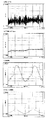
ここで、試験実行により検出器2及びエンジン制御部3から得られ測定部60に入力された時系列データをグラフに表したのが図4から図7であり、図4(a)は上記試験条件下での測定を300秒間行なった際の軸トルクTdの時系列データ、図4(c)は、図4(a)と同時間に測定された回転数Nの時系列データ、図4(d)は、図4(a)と同時間に測定されたスロットル開度Sの時系列データ、図5(a)、図5(c)、図5(d)は図4(a)、図4(c)、図4(d)のグラフの90s〜130sの期間の拡大グラフである。
Here, FIG. 4 to FIG. 7 are graphs showing time series data obtained from the
更に、図4(b)は図4(a)における軸トルクTdの100msの移動平均グラフであり、図5(b)は、図4(b)のグラフの90s〜130sの期間の拡大グラフである。本実施例の軸トルクTdの生データ(図4(a)、図5(a))には、演算部64において周波数解析を行なうと分かるように25Hz程度の信号成分を含んでいる。この信号成分はエンジン10の駆動に伴って出力されるトルクとは無関係であり、測定器等に起因するノイズとみなされるため、演算部64で移動平均処理を行ない、求められた平均軸トルクTdavgを以降、軸トルクTdとみなして処理に用いるものとする。
Further, FIG. 4B is a 100 ms moving average graph of the shaft torque Td in FIG. 4A, and FIG. 5B is an enlarged graph of the period of 90s to 130s in the graph of FIG. 4B. It is. The raw data (FIGS. 4A and 5A) of the axial torque Td of the present embodiment includes a signal component of about 25 Hz as can be understood from the frequency analysis performed by the
そして図4(b)〜(d)を一画面にグラフ表示させたのが図6であり、更に図6のグラフの90s〜130sの期間を拡大表示させたのが図7である。 FIG. 6 is a graph showing FIGS. 4B to 4D on one screen, and FIG. 7 is an enlarged view of the period of 90s to 130s in the graph of FIG.
図6、図7の試験測定結果からは、280sの期間において、軸トルクTd(平均軸トルクTdavg)が連続した上り階段状波形をしていること、そしてこの階段状波形のステップ毎にスロットル開度Sは、最小値から最大値まで振幅した少なくとも1周期分の略三角波形をしており、かつ、スロットル開度Sの最小及び最大振幅時には時間的な平坦部(本実施例では、約2s)を有していることが分かる。更に、回転数Nは、スロットル開度Sの波形に対応して、一定値に安定した定常データではなく、略正弦波形の過渡データとなっていることが分かる。 From the test measurement results of FIG. 6 and FIG. 7, the axial torque T d (average shaft torque T davg ) has a continuous upward staircase waveform for a period of 280 s , and every step of this staircase waveform. The throttle opening S has a substantially triangular waveform for at least one cycle with an amplitude from the minimum value to the maximum value, and a flat portion in time (in this embodiment, at the minimum and maximum amplitudes of the throttle opening S). It can be seen that it has about 2 s). Furthermore, it can be seen that the rotational speed N is not transient data that is stable at a constant value, but transient data having a substantially sinusoidal waveform corresponding to the waveform of the throttle opening S.
つまり、本実施例では、予め決められた試験条件の通りに試験が行なわれ、回転数Nが過渡状態の時の測定データが得られたことが分かる。 In other words, in this example, it was found that the test was performed according to the predetermined test conditions, and the measurement data when the rotational speed N was in the transient state was obtained.
次に、中央制御部5は、演算部64に補正データとエンジントルクTeの算出を命令する(S130)。ここで、エンジントルクTeと軸トルクTdの間には、Te=Td−I×dN/dtの関係が成立したことは上述した通りであり、回転数Nが一定値に安定していない過渡状態においては、エンジントルクTeと軸トルクTdは一致しないことが知られている。
Next, the
そこで、演算部64は、測定部60に入力された測定データのうち、回転数Nの時系列データの時間微分(dN/dt)を実行し、当該時間微分dN/dtと慣性モーメントI(本実施例では、0.14kgm2)の乗算を行なう。こうして得られた補正データの時系列データを図8に示す。尚、図8において、当該補正データは「慣性トルク」と称されている。
Therefore, the
更に、演算部64では、上記関係式Te=Td−I×dN/dtに基づき、図4(b)に示した平均軸トルクTdavgの時系列データから、先に算出された図8の補正データの時系列データを同一時間毎に減算して、エンジントルクTeの時系列データを得る。エンジントルクTeは、回転数Nの変化に伴うトルクへの影響が補正された状態のエンジン10の純粋なトルクを示すものである。算出されたエンジントルクTeの時系列データのグラフを図9に示す。
Further, in the
こうして得られたエンジントルクTeの時系列データと回転数Nの時系列データとスロットル開度Sの時系列データを同一時間毎に重ね合わせ同時に表示したのが図6のグラフである。尚、図7は、図6のグラフの90s〜130sの期間の拡大グラフである。 FIG. 6 is a graph in which the time series data of the engine torque Te , the time series data of the rotational speed N, and the time series data of the throttle opening S obtained in this way are superimposed at the same time and displayed simultaneously. FIG. 7 is an enlarged graph of the period of 90s to 130s in the graph of FIG.
ここでエンジントルクTeと回転数Nの関係特性を求めるために、表示部7は、図6のグラフに示す演算結果に基づき、スロットル開度Sをパラメータとして、各スロットル開度SにおけるエンジントルクTeと、当該エンジントルクTeと同一時間に測定された回転数Nのデータを読取ってグラフ上にプロットする。その結果を図10に示す。 Here, in order to obtain a relational characteristic between the engine torque Te and the rotational speed N, the display unit 7 uses the throttle opening S as a parameter based on the calculation result shown in the graph of FIG. and T e, read the data of the rotational speed N measured on the engine torque T e and the same time are plotted on a graph. The result is shown in FIG.
尚、パラメータとしてのスロットル開度Sの値は、図4(d)、図5(d)、図6からも分かるように、また予め決められた試験条件からも分かるように、0〜50%まで連続的に変化しているため、グラフへのプロット数、すなわち分解能を限りなく増やす程、グラフはグラデーション状になり、実際に、図10も濃淡を有するグラフとなっている。図10中、太実線で示されているのは、スロットル開度Sが10%、20%、30%、40%の時のエンジントルクTeと回転数Nの関係を示している。 Note that the value of the throttle opening S as a parameter is 0 to 50% as can be seen from FIGS. 4D, 5D and 6, and from the predetermined test conditions. Therefore, as the number of plots on the graph, that is, the resolution is increased as much as possible, the graph becomes a gradation, and actually FIG. 10 is also a graph having light and shade. In FIG. 10, the bold solid line shows the relationship between the engine torque Te and the rotational speed N when the throttle opening S is 10%, 20%, 30%, and 40%.
一方、本発明のエンジン計測装置1によらず、従来のエンジン計測装置によって求められたエンジントルクTeと回転数Nの関係特性を示すグラフが図11である。従来の計測装置では、スロットル開度Sを所定値(例えば、10%)に維持した状態、かつ、回転数Nが一定値に安定した定常状態、すなわち回転数Nの時間変化dN/dtが限りなく0に近くなった状態において、当該回転数Nとその時の軸トルクTdとを測定し、当該回転数Nと軸トルクTdの値を、スロットル開度S毎に都度、プロットすることによって、エンジントルクTeと回転数Nの関係特性を得ている。尚、回転数Nが一定値に安定するのには数十秒かかるものであるから、図11のグラフに必要なデータを取得するのにかかった試験時間は、数日に及ぶものである。
On the other hand, FIG. 11 is a graph showing the relational characteristic between the engine torque Te and the rotational speed N obtained by the conventional engine measurement device regardless of the
図10の実線部分と図11の実線部分とを比較すると、スロットル開度S毎に、同じようなエンジントルクTeと回転数Nの関係特性が示されていることが分かる。つまり、本発明のエンジン計測装置1によれば、従来のように回転数Nが一定値に安定している状態ではなく、回転数Nが変化している過渡状態で試験を行なうことによって、短時間(本実施例では約300s)でかつ一度にエンジントルクTeと回転数Nの関係を求めることが可能となる。しかも、本実施例では、パラメータであるスロットル開度Sの値を連続的に変化させているため、従来のように離散的なスロットル開度Sの値における特性のみならず、様々なスロットル開度Sにおける特性をも知ることが可能となる。従来の定常試験において、より連続的なスロットル開度S毎のエンジントルク特性を測定しようとすれば、更なる時間がかかるのである。
Comparing the solid line portion in FIG. 10 and the solid line portion in FIG. 11, it can be seen that the same relationship characteristics between the engine torque Te and the rotational speed N are shown for each throttle opening S. That is, according to the
更に、本実施例では、求められたエンジントルクTeと回転数Nの関係特性がエンジン10の性能を評価するのに有効な信頼性の高いデータであるか否かを確認する。
Further, in this embodiment, it is confirmed whether or not the obtained relational characteristic between the engine torque Te and the rotational speed N is highly reliable data effective for evaluating the performance of the
まず、評価部66は、試験条件が妥当であったか否かを評価する(S140)。試験条件の妥当性を評価するためには、測定部60で測定されたデータ及び演算部64で算出されたデータが、試験条件から得られると予想される特性範囲に存在し、また適切に偏りなく分布しているかを評価する。図12は、測定データのうち、平均軸トルクTdavgと、これと同一時間における回転数Nのデータセットの軌跡を表すグラフであり、図13は、演算部64で算出されたエンジントルクTeと、これと同一時間における回転数Nのデータセットの軌跡を表すグラフである。尚、以降、評価部66で評価に用いられるグラフは、もちろん表示部7に表示することが出来る。
First, the
図12からは、平均軸トルクTdavgが0〜70Nmの各々に対して、回転数Nのデータが0〜6000rpmまで偏りなく連続的に(隙間なく)分布していることが分かり、更にその分布傾向は、平均軸トルクTdavgがエンジントルクTeに変わっても変わらないということが図13から分かる。つまり、これらのことから、試験条件として、スロットル開度S、軸トルクTdの設定が妥当であり、過渡状態の回転数Nと、当該過渡状態において変化する軸トルクTdを測定することが出来たと言える。尚、試験条件の設定が妥当でなかった場合(S150)には、試験条件を見直す等して(S110)、再度試験を実行する(S120)。 From FIG. 12, it can be seen that for each of the average shaft torques T davg of 0 to 70 Nm, the data of the rotational speed N is distributed continuously (without gaps) from 0 to 6000 rpm without deviation, and further the distribution trend is that the average axial torque T DAVG does not change even change the engine torque T e is seen from FIG. 13. That is, from these facts, the throttle opening S and the shaft torque Td are appropriately set as test conditions, and the rotational speed N in the transient state and the shaft torque Td that changes in the transient state can be measured. It can be said that it was made. If the test conditions are not properly set (S150), the test conditions are reviewed (S110) and the test is executed again (S120).
尚、試験条件の妥当性をより精密に評価するために、エンジントルクTeと、これと同一時間における回転数Nのデータセットの度数分布表を作成し、度数に極端な偏りがないか否かの判断に基づいて試験条件の妥当性を評価してもよい。例えば、度数に極端な偏りがある場合には、求められたエンジントルクTeと回転数Nの関係特性の信頼性が高いとは言えないため、軸トルクTdの可変幅(振幅)、振幅周期や、スロットル開度Sの振幅周期、平坦部の時間等を見直す必要がある。 In order to more accurately evaluate the validity of the test conditions, a frequency distribution table of a data set of the engine torque Te and the rotational speed N at the same time is created, and whether or not there is an extreme bias in the frequency The validity of the test conditions may be evaluated based on the judgment. For example, if the frequency is extremely biased, it cannot be said that the relationship characteristic between the obtained engine torque Te and the rotational speed N is highly reliable, so the variable width (amplitude) and amplitude of the shaft torque Td It is necessary to review the period, the amplitude period of the throttle opening S, the time of the flat portion, and the like.
試験条件が妥当であると評価された場合(S150)、評価部66は、測定部60で測定された測定データの信頼性を評価する(S160)。測定データの信頼性を評価するためには、演算部64で算出されたエンジントルクTeと、これと同一時間における回転数Nのデータセットの度数分布表を作成し、度数に極端な偏りがないか否かの判断に基づいて行なう。
When it is evaluated that the test conditions are appropriate (S150), the
更に、この度数分布表において、演算部64は、各データセットから、当該データセットと同日時間におけるスロットル開度Sのデータを抽出し、先の度数分布表における分布地点毎にスロットル開度Sの平均値及び標準偏差(ばらつき)を求める。つまりここでは、任意のエンジントルクTeと回転数Nのデータセットにおけるスロットル開度Sの平均値と標準偏差が求められる。
Further, in the frequency distribution table, the
これより、エンジントルクTeと回転数Nの全データセットにおいて、スロットル開度Sの値のばらつきが2,3%以内に収まっていれば、測定データの信頼性が高いと言える。しかし、スロットル開度Sのばらつきが2,3%以上のデータセット数が多い場合には、測定データとしては信頼性が低く、試験環境の見直し等、測定データのばらつきの要因を除去した上で再度試験が行なう必要がある(S120)。 From this, it can be said that the reliability of the measurement data is high if the variation in the value of the throttle opening S is within 2 to 3% in the entire data set of the engine torque Te and the rotational speed N. However, when there are many data sets with a variation in throttle opening S of 2 to 3% or more, the reliability of the measurement data is low, and after removing factors of measurement data variation such as reviewing the test environment The test needs to be performed again (S120).
測定データの信頼性が高いと評価された場合(S170)、評価部66は補正データの有効性を評価する(S180)。補正データの有効性を評価するためには、元の測定データである平均軸トルクTdavgと回転数Nの関係が、平均軸トルクTdavgに補正データが加味されることでどのように変化するかを確認すればよい。
When it is evaluated that the reliability of the measurement data is high (S170), the
ここで、図14は、スロットル開度Sが20%の時の、平均軸トルクTdavgと回転数Nの関係を示すグラフであり、図15は、図14同様スロットル開度Sが20%の時の、平均軸トルクTdavgに補正データを加味したエンジントルクTeと回転数Nの関係を示すグラフである。また、図示しないが、各図の関係において、スロットル開度Sの標準偏差グラフも作成するのが望ましい。 Here, FIG. 14 is a graph showing the relationship between the average shaft torque T davg and the rotational speed N when the throttle opening S is 20%, and FIG. 15 shows that the throttle opening S is 20% as in FIG. when is a graph showing the average axial torque T DAVG the engine torque T e in consideration of the correction data the relationship between the rotational speed N. Although not shown, it is desirable to create a standard deviation graph of the throttle opening S in relation to each figure.
図14のグラフからは、補正データが加味される前の平均軸トルクTdavgは、1の回転数Nに対して2つの値を有する「2値性」を示していることが分かる。これは、同じ回転数Nでも回転数を上げる時と下げる時では、エンジン10の動作が異なり、それによってトルク等の値も異なるからである。この「2値性」の現象は、任意の平均軸トルクTdavgと回転数Nにおけるスロットル開度Sの標準偏差(図示せず)を求めた際に、いずれのポイントにおいても2.5〜5%と、大きなばらつきを有していることからも分かる。
From the graph of FIG. 14, it can be seen that the average shaft torque T davg before the correction data is taken into account exhibits “binary property” having two values with respect to the rotation speed N of one. This is because even when the rotational speed is the same N, the
しかし、図15においては、エンジントルクTeは「2値性」を有しておらず、エンジントルクTeと回転数Nとの関係が一義的に決まり、これらは相関関係を有している。つまり、演算部66で算出された補正データは有効であることが言える。このことは、任意のエンジントルクTeと回転数Nにおけるスロットル開度Sの標準偏差(図示せず)を求めた際に、いずれのポイントにおいてもばらつきが2,3%以内に収まっていることからも言える。
However, in FIG. 15, the engine torque T e has no "binary property", the relationship between the engine torque T e and the rotation speed N is determined uniquely, which have a correlation . That is, it can be said that the correction data calculated by the
尚、図15のグラフは、図11における従来の計測装置によって求められたグラフのうち、スロットル開度20%の曲線に近似していることからも、演算部66で算出された補正データが有効であり、回転数Nが過渡状態にある時に測定されたデータによっても、定常状態において求められたグラフに相当する結果が得られるものであることが分かる。
Note that the correction data calculated by the
補正データが有効でないと評価された場合には(S190)、演算部64での演算内容や、慣性モーメントIの定義値を見直す等して、再度、補正データ及びエンジントルクTeを算出する(S130)。
When it is evaluated that the correction data is not valid (S190), the correction data and the engine torque Te are calculated again by reviewing the calculation contents in the
尚、S140における試験条件の妥当性評価、S160における測定データの信頼性評価、S180における補正データの有効性評価の順序は本実施例で行なわれた順序に限るものではなく、また、これらの評価が一体的総合的に行なわれてもよい。 The order of the validity evaluation of the test conditions in S140, the reliability evaluation of the measurement data in S160, and the validity evaluation of the correction data in S180 is not limited to the order performed in this embodiment, and these evaluations are also performed. May be performed in an integrated manner.
また、S130でエンジントルクTeと補正データを算出するに先立って、測定データ(平均軸トルクTdavgと回転数Nとスロットル開度S)のみから、表示部7に各種データ間の関係を示すグラフや、度数分布表、平均値グラフ、標準偏差グラフ等を表示させ、試験条件の妥当性、測定データの信頼性を評価しておいてもよい。 Also, shown prior to calculating the correction data and the engine torque T e, from only the measurement data (average axial torque T DAVG the rotational speed N and the throttle opening S), the relationship between the various data on the display unit 7 in S130 A graph, a frequency distribution table, an average value graph, a standard deviation graph, or the like may be displayed to evaluate the validity of test conditions and the reliability of measurement data.
また、これら3種類の評価は、必ずしも全てが行なわれる必要はなく、測定環境や、エンジン計測装置の性能・測定精度等に応じて、いずれかが省略されてもよい。 Further, it is not always necessary to perform all of these three types of evaluation, and any of them may be omitted depending on the measurement environment, the performance / measurement accuracy of the engine measurement device, and the like.
補正データが有効であると評価された場合には(S190)、中央制御部5は、表示部7に表示するデータを選択して、表示させる(S200)。例えば、図10に示されたような、スロットル開度Sをパラメータとした、エンジントルクTeと回転数Nの関係特性は、エンジン10の性能を端的に表すグラフとして最も重要である。尚、開発ないし製造されたエンジン10の性能評価を行なうエンジンベンチに、本発明のエンジン計測装置1が含まれる場合には、表示部7に表示されたグラフに基づいて、エンジン10が設計目標ないし所定の規格を満足しているか否かを確認し、目標外ないし規格外であると判断された場合には、エンジン10の見直しを行なう。
When it is evaluated that the correction data is valid (S190), the
尚、表示部7には、測定データ及び演算部64で算出されたデータに基づいて、任意の関係グラフや、標準偏差グラフや、度数分布表を表示することが可能である。もちろん、表示部7は、これまでの評価部66における評価に用いた全てのグラフを表示することが可能である。
The display unit 7 can display an arbitrary relation graph, standard deviation graph, and frequency distribution table based on the measurement data and the data calculated by the
以上、エンジン計測装置の実施例につき説明したが、本発明のエンジン計測装置は、上記実施例で説明した構成要件の全てを備えたエンジン計測装置に限定されるものではなく、各種の変更及び修正が可能である。また、かかる変更及び修正についても本発明の特許請求の範囲に属することは言うまでもない。 As described above, the embodiment of the engine measuring device has been described. However, the engine measuring device of the present invention is not limited to the engine measuring device including all of the configuration requirements described in the above embodiment, and various changes and modifications. Is possible. Further, it goes without saying that such changes and modifications belong to the scope of the claims of the present invention.
実施例では、エンジン10をダイナモメータ12に接続した台上試験において、短時間に、エンジントルクTeと回転数Nの関係特性を求めるための一例を示したが、本発明のエンジン計測装置は、エンジン10に空気や燃料を供給して、燃料を燃焼させながら、回転数や負荷トルクを変化させて、エンジン性能の測定・評価を行なう場合にも用いることが出来る。
In the embodiment, in the bench test in which the
このような試験においては、パラメータとして、エンジン入力側は空気注入量、燃料注入量、燃料と空気の混合比、点火タイミングを、エンジン出力側はエンジントルクTe、回転数Nに加え、排気ガス成分、排気ガス量を得ることが出来るから、エンジン計測装置によって求められたエンジントルクTeと回転数Nの関係特性を、これらパラメータ毎に求め、トランスミッション制御に役立てることも可能となる。 In such a test, the engine input side includes parameters such as air injection amount, fuel injection amount, fuel / air mixture ratio, ignition timing, engine output side in addition to engine torque T e and engine speed N, and exhaust gas. Since the component and the exhaust gas amount can be obtained, the relational characteristic between the engine torque Te and the rotational speed N obtained by the engine measuring device can be obtained for each of these parameters, and can be used for transmission control.
例えば、燃費(燃料流量とエンジントルクTeの比)をパラメータとして、エンジントルクTeと回転数Nの関係を求めれば、この関係に基づいて、効率的なトランスミッション制御方法を確立することが可能となる。また、排気ガス量をパラメータとして、エンジントルクTeと回転数Nの関係を求めれば、近年の排気ガス規制に対応したトランスミッション制御方法を確立することが可能となる。 For example, fuel consumption (the ratio of fuel flow rate and the engine torque T e) as a parameter, by obtaining the relationship between the rotational speed N and the engine torque T e, it can be based on this relationship, establishing an efficient transmission control method It becomes. Further, if the relationship between the engine torque Te and the rotational speed N is obtained using the exhaust gas amount as a parameter, it is possible to establish a transmission control method corresponding to recent exhaust gas regulations.
尚、本実施例でのダイナモメータによる台上試験でエンジン性能を計測するエンジン計測装置に代えて、台上試験でもダイナモメータの代わりにミッション、サスペンション、車輪を接続した実車試験や、台上試験ではない実走行試験に用いられるエンジン計測装置であっても、信号処理部6によりエンジントルクTeを求めることも出来る。これらの場合には、評価部66において試験条件の妥当性評価、及び/又は、測定データの信頼性評価、及び/又は、算出された補正データやエンジントルクTeの有効性評価を実施し、小さいトルクから最大トルクまでエンジンの全ての状態が平均的に分布したデータを得るようにすることによって、演算部64により算出されたエンジントルクTeの信頼性を確保することが出来る。
In addition, instead of the engine measuring device that measures the engine performance in the bench test with the dynamometer in this embodiment, the bench test also includes an actual vehicle test in which a mission, suspension, and wheels are connected instead of the dynamometer, and a bench test. even engine measurement device for use in actual running test not can also be determined engine torque T e by the
1:エンジン計測装置
10:エンジン
12:ダイナモメータ
14:架台
16:トルク伝達軸
16a:ユニバーサルジョイント
2:検出器
3:エンジン制御部
4:ダイナモメータ制御部
5:中央制御部
6:信号処理部
60:測定部
62:メモリ
64:演算部
66:評価部
7:表示部
1: Engine measuring device 10: Engine 12: Dynamometer 14: Mount 16: Torque transmission shaft 16a: Universal joint 2: Detector 3: Engine control unit 4: Dynamometer control unit 5: Central control unit 6: Signal processing unit 60 : Measurement unit 62: Memory 64: Calculation unit 66: Evaluation unit 7: Display unit
Claims (5)
前記エンジン計測装置は、前記エンジンの回転数に起因するスロットル開度及び、前記ダイナモメータの負荷トルクを制御する中央制御部と、
前記エンジンの出力軸に接続され、前記中央制御部の制御により駆動する前記エンジンの回転数と軸トルクを少なくとも含む測定データを負荷状態で検出する検出器と、
前記検出器からの測定データに基づいてエンジントルクを負荷状態で計測する信号処理部とを備え、
前記中央制御部は、前記回転数が過渡状態となり、前記軸トルクが前記過渡状態の期間に変化するような制御を行ない、
前記信号処理部は、前記検出器で検出された負荷状態の前記回転数及び軸トルクの時系列データに基づいて、前記エンジントルクを負荷状態で算出し、過渡状態データからエンジントルクを計測することを特徴とするエンジン計測装置。 In an engine measurement device for measuring engine performance in a bench test performed by an engine and a dynamometer connected to the engine,
The engine measurement device includes a central control unit that controls a throttle opening caused by the engine speed and a load torque of the dynamometer,
A detector that is connected to the output shaft of the engine and detects measurement data including at least the rotational speed and shaft torque of the engine driven by the control of the central control unit in a load state ;
A signal processing unit that measures engine torque in a load state based on measurement data from the detector;
The central control unit performs control such that the rotational speed is in a transient state and the shaft torque is changed during the transient state,
The signal processing unit calculates the engine torque in the load state based on the time series data of the rotation speed and the shaft torque in the load state detected by the detector, and measures the engine torque from the transient state data. An engine measuring device.
Priority Applications (2)
| Application Number | Priority Date | Filing Date | Title |
|---|---|---|---|
| JP2004332471A JP4547239B2 (en) | 2004-11-16 | 2004-11-16 | Engine measuring device |
| US11/092,757 US7142974B2 (en) | 2004-11-16 | 2005-03-30 | Engine measuring equipment |
Applications Claiming Priority (1)
| Application Number | Priority Date | Filing Date | Title |
|---|---|---|---|
| JP2004332471A JP4547239B2 (en) | 2004-11-16 | 2004-11-16 | Engine measuring device |
Publications (2)
| Publication Number | Publication Date |
|---|---|
| JP2005308712A JP2005308712A (en) | 2005-11-04 |
| JP4547239B2 true JP4547239B2 (en) | 2010-09-22 |
Family
ID=35437641
Family Applications (1)
| Application Number | Title | Priority Date | Filing Date |
|---|---|---|---|
| JP2004332471A Expired - Fee Related JP4547239B2 (en) | 2004-11-16 | 2004-11-16 | Engine measuring device |
Country Status (2)
| Country | Link |
|---|---|
| US (1) | US7142974B2 (en) |
| JP (1) | JP4547239B2 (en) |
Families Citing this family (25)
| Publication number | Priority date | Publication date | Assignee | Title |
|---|---|---|---|---|
| KR101188160B1 (en) * | 2005-05-09 | 2012-10-05 | 가부시키가이샤 에이 앤 디 | Engine measurement device |
| AT7889U3 (en) * | 2005-06-15 | 2006-12-15 | Avl List Gmbh | METHOD FOR TESTING A DYNAMIC TORQUE GENERATOR AND DEVICE FOR DETERMINING THE DYNAMIC BEHAVIOR OF A CONNECTION SHAFT |
| JP4566900B2 (en) * | 2005-12-09 | 2010-10-20 | 株式会社エー・アンド・デイ | Engine measuring device |
| EP2135054B1 (en) * | 2007-04-13 | 2020-09-09 | Rototest International AB | Method and device for testing of a combustion engine or an associated structure and a rig |
| US8036844B2 (en) * | 2008-03-24 | 2011-10-11 | Honeywell International Inc. | Transient performance data phase compensation system and method |
| US7926336B2 (en) * | 2008-09-04 | 2011-04-19 | Vickio Jr Louis P | Dynamometer |
| US9207149B2 (en) * | 2012-01-13 | 2015-12-08 | Meidensha Corporation | Drive-train testing system |
| US9171387B2 (en) * | 2012-08-24 | 2015-10-27 | Synerscope Bv | Data visualization system |
| SE537438C2 (en) | 2013-06-10 | 2015-04-28 | Scania Cv Ab | Procedure for monitoring and storing operating quantities in an internal combustion engine |
| FR3012882B1 (en) | 2013-11-05 | 2015-11-27 | Snecma | TECHNICAL TEST METHOD |
| CN103884459B (en) * | 2014-03-27 | 2016-03-16 | 奇瑞汽车股份有限公司 | A kind of measurement of power equipment |
| AT514725B1 (en) * | 2014-11-28 | 2016-06-15 | Avl List Gmbh | Method and device for determining the propulsion torque |
| JP6044649B2 (en) * | 2015-01-19 | 2016-12-14 | 株式会社明電舎 | Control device for dynamometer system |
| US10113936B2 (en) * | 2015-06-01 | 2018-10-30 | Rolls-Royce Corporation | Closed-loop engine testing system |
| WO2017158838A1 (en) | 2016-03-18 | 2017-09-21 | 富士通株式会社 | Engine torque estimation device, engine control system, and engine torque estimation method |
| JP6659491B2 (en) * | 2016-07-27 | 2020-03-04 | 株式会社エー・アンド・デイ | Engine test equipment |
| AT519261B1 (en) * | 2016-12-05 | 2018-05-15 | Avl List Gmbh | Method and test bench for carrying out a test run with a drive train |
| CN106872174A (en) * | 2017-02-22 | 2017-06-20 | 重庆理工大学 | Automobile transmission rack Knock test engine transient cycle moment of torsion analogy method |
| JP6497408B2 (en) * | 2017-04-14 | 2019-04-10 | 株式会社明電舎 | Electric inertia control device |
| WO2019055773A1 (en) | 2017-09-15 | 2019-03-21 | MultiPhase Solutions, Inc. | Halogen selective detection gas chromatography for the on-line analysis and control of selective oxidation chemical production processes |
| GB2576025A (en) * | 2018-08-01 | 2020-02-05 | Comb Order Ltd | Synchronous real time dynamometer |
| JP6687086B1 (en) * | 2018-11-07 | 2020-04-22 | 株式会社明電舎 | Electric inertia control device |
| GB2617870B (en) * | 2022-05-30 | 2024-06-19 | Autoneura Ltd | A method of transient testing a prime mover |
| CN115901046B (en) * | 2023-02-15 | 2023-05-30 | 灵翼飞航(天津)科技有限公司 | Multi-load unmanned aerial vehicle engine dynamometer |
| CN118500596B (en) * | 2024-06-18 | 2024-11-15 | 湖南中旗动力设备有限公司 | Output torque dynamometer for engine |
Citations (4)
| Publication number | Priority date | Publication date | Assignee | Title |
|---|---|---|---|---|
| JP2000111452A (en) * | 1998-10-02 | 2000-04-21 | Shigeno:Kk | Method for measuring performance of engine |
| JP2000321175A (en) * | 1999-05-14 | 2000-11-24 | Horiba Ltd | Method for creating map to be used for engine-testing device or vehicle-testing device |
| JP2004157026A (en) * | 2002-11-07 | 2004-06-03 | Ono Sokki Co Ltd | Measuring method and device for engine performance |
| JP2005090353A (en) * | 2003-09-17 | 2005-04-07 | Hino Motors Ltd | Transient engine performance adapting method and system |
Family Cites Families (13)
| Publication number | Priority date | Publication date | Assignee | Title |
|---|---|---|---|---|
| JPS5942882B2 (en) * | 1978-04-29 | 1984-10-18 | 株式会社日立製作所 | Control device |
| US4653274A (en) * | 1984-03-06 | 1987-03-31 | David Constant V | Method of controlling a free piston external combustion engine |
| JP3543337B2 (en) * | 1993-07-23 | 2004-07-14 | 日産自動車株式会社 | Signal processing device |
| JP2981965B2 (en) * | 1993-11-29 | 1999-11-22 | 本田技研工業株式会社 | Vehicle driving force control device |
| JP3399062B2 (en) * | 1993-12-22 | 2003-04-21 | トヨタ自動車株式会社 | Failure detection device for automatic transmission for vehicles |
| JP3203976B2 (en) * | 1994-09-05 | 2001-09-04 | 日産自動車株式会社 | Vehicle driving force control device |
| US6018694A (en) * | 1996-07-30 | 2000-01-25 | Denso Corporation | Controller for hybrid vehicle |
| JP4590773B2 (en) * | 2000-06-22 | 2010-12-01 | 株式会社デンソー | Integrated vehicle control system |
| JP3956693B2 (en) * | 2001-12-27 | 2007-08-08 | トヨタ自動車株式会社 | Integrated vehicle motion controller |
| JP4235116B2 (en) | 2004-01-09 | 2009-03-11 | 日野自動車株式会社 | Apparatus and method for testing transient characteristics of internal combustion engine |
| JP4198605B2 (en) | 2004-01-09 | 2008-12-17 | 日野自動車株式会社 | Transient engine test apparatus and method |
| JP4145806B2 (en) | 2004-01-09 | 2008-09-03 | 日野自動車株式会社 | Transient engine test apparatus and method |
| JP2005199542A (en) | 2004-01-15 | 2005-07-28 | Fuji Xerox Co Ltd | Printer apparatus |
-
2004
- 2004-11-16 JP JP2004332471A patent/JP4547239B2/en not_active Expired - Fee Related
-
2005
- 2005-03-30 US US11/092,757 patent/US7142974B2/en not_active Expired - Fee Related
Patent Citations (4)
| Publication number | Priority date | Publication date | Assignee | Title |
|---|---|---|---|---|
| JP2000111452A (en) * | 1998-10-02 | 2000-04-21 | Shigeno:Kk | Method for measuring performance of engine |
| JP2000321175A (en) * | 1999-05-14 | 2000-11-24 | Horiba Ltd | Method for creating map to be used for engine-testing device or vehicle-testing device |
| JP2004157026A (en) * | 2002-11-07 | 2004-06-03 | Ono Sokki Co Ltd | Measuring method and device for engine performance |
| JP2005090353A (en) * | 2003-09-17 | 2005-04-07 | Hino Motors Ltd | Transient engine performance adapting method and system |
Also Published As
| Publication number | Publication date |
|---|---|
| US20060106526A1 (en) | 2006-05-18 |
| JP2005308712A (en) | 2005-11-04 |
| US7142974B2 (en) | 2006-11-28 |
Similar Documents
| Publication | Publication Date | Title |
|---|---|---|
| JP4547239B2 (en) | Engine measuring device | |
| JP5264429B2 (en) | How to determine the correct flow rate of fuel to a vehicle engine for diagnostic testing | |
| JP4362533B2 (en) | Engine measuring device | |
| JP4566900B2 (en) | Engine measuring device | |
| US7860665B2 (en) | Method and system for determining the torque induced in a rotating shaft | |
| US7484405B2 (en) | System and method for engine sound calibration | |
| Luján et al. | A methodology for combustion detection in diesel engines through in-cylinder pressure derivative signal | |
| JP6849376B2 (en) | Piston-Method and operation monitoring device for monitoring the operation of the device for variably adjusting the cylinder compression ratio in an internal combustion engine. | |
| JP4778876B2 (en) | Engine measuring device | |
| US8170777B2 (en) | Indicating system and method for determining an engine parameter | |
| US20120279289A1 (en) | Method for Determining Emission Values Of A Gas Turbine, And Apparatus For Carrying Out Said Method | |
| US6481273B2 (en) | Frequency response test method for an in-vehicle air/fuel ratio sensor | |
| US7742882B2 (en) | Method for determination of mean engine torque | |
| JP2009524754A (en) | Method for diagnosing a catalyst arranged in the exhaust gas region of an internal combustion engine and device for carrying out the method | |
| JPH0752129B2 (en) | Engine output indicator | |
| EP2392801B1 (en) | Method and Device for Detecting the Cetane Number | |
| US8600645B2 (en) | Induction backfire compensation for motorcycles | |
| RU2219510C2 (en) | Diesel engine testing method | |
| JP2012092812A (en) | Oil consumption evaluation analysis system | |
| JP2004011487A (en) | Method and apparatus for identifying gaseous fuel | |
| JPH0719915Y2 (en) | Control unit inspection device | |
| JP2003294582A (en) | Test method and test device for vehicle drive source output transmitter | |
| JPH0648135Y2 (en) | Control unit inspection device | |
| JPH02176441A (en) | Control-unit checking apparatus | |
| CN108071457A (en) | For identifying the method for the failure in the exhaust system of the waste gas stream of guiding internal combustion engine |
Legal Events
| Date | Code | Title | Description |
|---|---|---|---|
| A521 | Written amendment |
Free format text: JAPANESE INTERMEDIATE CODE: A523 Effective date: 20050804 |
|
| A621 | Written request for application examination |
Free format text: JAPANESE INTERMEDIATE CODE: A621 Effective date: 20070906 |
|
| A977 | Report on retrieval |
Free format text: JAPANESE INTERMEDIATE CODE: A971007 Effective date: 20100113 |
|
| A131 | Notification of reasons for refusal |
Free format text: JAPANESE INTERMEDIATE CODE: A131 Effective date: 20100223 |
|
| A521 | Written amendment |
Free format text: JAPANESE INTERMEDIATE CODE: A523 Effective date: 20100419 |
|
| TRDD | Decision of grant or rejection written | ||
| A01 | Written decision to grant a patent or to grant a registration (utility model) |
Free format text: JAPANESE INTERMEDIATE CODE: A01 Effective date: 20100629 |
|
| A01 | Written decision to grant a patent or to grant a registration (utility model) |
Free format text: JAPANESE INTERMEDIATE CODE: A01 |
|
| A61 | First payment of annual fees (during grant procedure) |
Free format text: JAPANESE INTERMEDIATE CODE: A61 Effective date: 20100705 |
|
| FPAY | Renewal fee payment (event date is renewal date of database) |
Free format text: PAYMENT UNTIL: 20130709 Year of fee payment: 3 |
|
| R150 | Certificate of patent or registration of utility model |
Free format text: JAPANESE INTERMEDIATE CODE: R150 |
|
| R250 | Receipt of annual fees |
Free format text: JAPANESE INTERMEDIATE CODE: R250 |
|
| LAPS | Cancellation because of no payment of annual fees |