JP4532639B2 - Multiple liquid waste treatment equipment - Google Patents
Multiple liquid waste treatment equipment Download PDFInfo
- Publication number
- JP4532639B2 JP4532639B2 JP2000004385A JP2000004385A JP4532639B2 JP 4532639 B2 JP4532639 B2 JP 4532639B2 JP 2000004385 A JP2000004385 A JP 2000004385A JP 2000004385 A JP2000004385 A JP 2000004385A JP 4532639 B2 JP4532639 B2 JP 4532639B2
- Authority
- JP
- Japan
- Prior art keywords
- liquid waste
- liner
- canister
- float
- bottle
- Prior art date
- Legal status (The legal status is an assumption and is not a legal conclusion. Google has not performed a legal analysis and makes no representation as to the accuracy of the status listed.)
- Expired - Lifetime
Links
Images


Classifications
-
- A—HUMAN NECESSITIES
- A61—MEDICAL OR VETERINARY SCIENCE; HYGIENE
- A61M—DEVICES FOR INTRODUCING MEDIA INTO, OR ONTO, THE BODY; DEVICES FOR TRANSDUCING BODY MEDIA OR FOR TAKING MEDIA FROM THE BODY; DEVICES FOR PRODUCING OR ENDING SLEEP OR STUPOR
- A61M1/00—Suction or pumping devices for medical purposes; Devices for carrying-off, for treatment of, or for carrying-over, body-liquids; Drainage systems
- A61M1/60—Containers for suction drainage, adapted to be used with an external suction source
- A61M1/604—Bag or liner in a rigid container, with suction applied to both
-
- A—HUMAN NECESSITIES
- A61—MEDICAL OR VETERINARY SCIENCE; HYGIENE
- A61M—DEVICES FOR INTRODUCING MEDIA INTO, OR ONTO, THE BODY; DEVICES FOR TRANSDUCING BODY MEDIA OR FOR TAKING MEDIA FROM THE BODY; DEVICES FOR PRODUCING OR ENDING SLEEP OR STUPOR
- A61M1/00—Suction or pumping devices for medical purposes; Devices for carrying-off, for treatment of, or for carrying-over, body-liquids; Drainage systems
- A61M1/71—Suction drainage systems
- A61M1/78—Means for preventing overflow or contamination of the pumping systems
- A61M1/782—Means for preventing overflow or contamination of the pumping systems using valves with freely moving parts, e.g. float valves
-
- A—HUMAN NECESSITIES
- A61—MEDICAL OR VETERINARY SCIENCE; HYGIENE
- A61M—DEVICES FOR INTRODUCING MEDIA INTO, OR ONTO, THE BODY; DEVICES FOR TRANSDUCING BODY MEDIA OR FOR TAKING MEDIA FROM THE BODY; DEVICES FOR PRODUCING OR ENDING SLEEP OR STUPOR
- A61M1/00—Suction or pumping devices for medical purposes; Devices for carrying-off, for treatment of, or for carrying-over, body-liquids; Drainage systems
- A61M1/88—Draining devices having means for processing the drained fluid, e.g. an absorber
- A61M1/882—Draining devices provided with means for releasing antimicrobial or gelation agents in the drained fluid
Landscapes
- Health & Medical Sciences (AREA)
- Heart & Thoracic Surgery (AREA)
- Vascular Medicine (AREA)
- Engineering & Computer Science (AREA)
- Anesthesiology (AREA)
- Biomedical Technology (AREA)
- Hematology (AREA)
- Life Sciences & Earth Sciences (AREA)
- Animal Behavior & Ethology (AREA)
- General Health & Medical Sciences (AREA)
- Public Health (AREA)
- Veterinary Medicine (AREA)
- External Artificial Organs (AREA)
- Accommodation For Nursing Or Treatment Tables (AREA)
- Apparatus For Disinfection Or Sterilisation (AREA)
Description
【0001】
【発明の属する技術分野】
本発明は、例えば医療現場において廃棄する必要のある血液やその他の体液や分泌物、或いは膿汁または患部の洗浄に使用した生理食塩水等の液状廃棄物を吸引して凝固処理し、廃棄するための液状廃棄物処理装置に関するものである。
【0002】
【従来の技術】
医療現場において、特に外科手術を行う際に生じる廃棄する必要のある血液やその他の体液や分泌物、或いは膿汁または患部の洗浄に使用した生理食塩水等の液状廃棄物は、吸引機で容器や収集袋に集められて廃棄焼却処分される。
【0003】
しかし、かかる液状廃棄物には有害な細菌等が含まれている場合があり、容器や収集袋が破損したり、液状廃棄物を収集袋の容量以上に過剰に吸引してしまった場合、液状廃棄物が外部に漏れ、医療従事者、入院患者等に二次感染する虞がある。
【0004】
これを防止するため収集袋内に吸水性材料を配置し、液状廃棄物を凝固させる装置が存在するが、収集袋内に液状廃棄物を凝固させる吸水性材料を配置する方法として、非透水性のシートと吸水性シートを貼り合わせ、吸水性シートが内面側になるように収集袋を形成するものや、収集袋内に液状廃棄物を吸引した後に用意しておいた吸水性材料を投下するもの、また収集袋底部に吸水性材料を固着させておくもの等がある。
【0005】
また、液状廃棄物の収集処理能力を増大するために収集袋を2連にしたものや同一円周上に車座に4連或いは6連にしたものが提案されており、多数の収集袋が直列連結された場合には最終段の収集袋にシャットオフバルブ等を設けて液状廃棄物の吸引を自動的に止めるようになっている。
【0006】
【発明が解決しようとする課題】
しかしながら、前述の従来例において、液状廃棄物の収集処理能力を増大するために収集袋を同一円周上に多数連結した場合には、一方向から全ての収集袋を見通すことが出来ないため処理装置の使用者はあとどれくらいの収容許容量があるかを容易に確認することが出来なかった。
【0007】
また、多数の収集袋が直列連結された場合には最終段の収集袋にシャットオフバルブを設ける必要があるため最終段の収集袋を他の収集袋とは特殊な収集袋にしなければならず、収集袋の種類が増大して製造コスト及び製品管理コストが増大するという問題がある。
【0008】
また、非透水性のシートと吸水性のシートを貼り合わせて構成した処理装置は、多重構造をなしているため内部が不可視となり、また折り畳みにくく、収納および運搬に不便があった。
【0009】
また収集袋内に液状廃棄物を吸引した後に投下する吸水性材料を用意した処理装置においては、当然吸水性材料を投下するまで凝固が起こらないため、作業途中で転倒させた場合に不安が残り、また一度凝固させた後に追加して吸引を行うことが出来なかった。
【0010】
また、収集袋底部に吸水性材料を固着させた処理装置においては、液状廃棄物の吸引が進行するにつれて凝固速度が低下するという問題があった。
【0011】
本発明は前記課題を解決するものであり、その目的とするところは、複数個連結されるキャニスターボトルの種類を共通化することが出来、液状廃棄物の収集処理能力を増大しても内容量の視認が容易であり、吸引した液状廃棄物をより早く凝固させることが出来る多連型液状廃棄物処理装置を提供することにある。
【0012】
【課題を解決するための手段】
前記目的を達成するための本発明に係る多連型液状廃棄物処理装置は、液状廃棄物を吸引する吸引口と、液状廃棄物を排出する排出口と、前記吸引口から吸引した液状廃棄物を収容するキャニスターボトルを複数個連結した多連型液状廃棄物処理装置であって、夫々の前記キャニスターボトルは、一次側吸引ホースにそれぞれ並列に接続された各吸引通路に連通され、内部を負圧にする排気口を有し、一方のキャニスターボトルの排出口と他方のキャニスターボトルの吸引口とが接続されて直列に連結され、最終段のキャニスターボトルの排出口が閉塞され、前記キャニスターボトル内の上端部内側には前記排気口の吸引通路を閉塞し得るストップバルブが設けられ、前記ストップバルブは前記キャニスターボトル内のフロートが天端部まで浮上しない間は前記ストップバルブの自重により下方位置に維持されて前記吸引通路を確保し、前記液状廃棄物が前記キャニスターボトル内部に吸引されて該液状廃棄物により浮上したフロートが上昇して前記キャニスターボトルの天端部まで到達した際に該フロートの天端面が前記ストップバルブに当接して該ストップバルブの自重に抗して該ストップバルブを上昇させ、前記吸引通路を閉塞することを特徴とする。
【0013】
本発明は、上述の如く構成したので、一方のキャニスターボトルの排出口と他方のキャニスターボトルの吸引口とが接続されて直列に連結されると共に、最終段のキャニスターボトルの排出口が閉塞され、夫々のキャニスターボトルの排気口から排気して内部を負圧にすることで直列に連結された複数のキャニスターボトルに順次、液状廃棄物を吸引して収容することが出来る。
【0014】
また、最終段のキャニスターボトルも他のキャニスターボトルと共通化出来るので、キャニスターボトルの種類を低減することが出来、製造コスト及び製品管理コストを低減することが出来る。
【0015】
また、前記複数のキャニスターボトルを直列に連結された順番で一直線上に配置した場合には、一方向から全てのキャニスターボトルを見通すことが出来、液状廃棄物はキャニスターボトルの配列順に収容されるので、該処理装置の使用者はあとどれくらいの収容許容量があるかを容易に確認することが出来る。
【0016】
また、前記キャニスターボトルが、外容器と、該外容器内に収容され、内側に凝固剤を有する内袋とから構成された場合には、液状廃棄物を内袋内で凝固させて、内袋ごと廃棄処理することが出来、衛生的な処理装置とすることが出来る。
【0017】
また、前記キャニスターボトルの内袋が、その内側に比重が1より小さく、且つ前記凝固剤を保持したフロートを有する場合には、フロートが常に気液界面に浮上した位置に維持されるためフロートの位置を確認することで液面の位置を外から確認することが出来、使用者は確実にキャニスターボトルの使用状態と、残存許容容量を確認することが出来る。
【0018】
【発明の実施の形態】
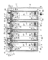
図により本発明に係る多連型液状廃棄物処理装置の一実施形態を具体的に説明する。図1は本発明に係る多連型液状廃棄物処理装置の構成を示す外観正面図、図2は本発明に係る多連型液状廃棄物処理装置の構成を示す外観平面図、図3は本発明に係る多連型液状廃棄物処理装置の構成を示す外観側面図である。
【0019】
また、図4は本発明に係る多連型液状廃棄物処理装置の吸引通路を説明する横断面説明図、図5は本発明に係る多連型液状廃棄物処理装置の吸引通路を説明する縦断面説明図である。
【0020】
また、図6は共通化されたキャニスターボトルが最終段となる際に排出口を閉塞する構成と、更に下流側にキャニスターボトルを連結する構成とに適宜選択的に変更する様子を示す斜視説明図、図7は内袋の天端部に設けられた蓋に形成された吸引口と閉塞栓とに接続管或いはペイシェントホースを接続した際の弁部材の作用を示す説明図である。
【0021】
また、図8(a)はキャニスターボトルの内袋と該内袋内に収容された凝固剤を保持したフロートの構成を示す外観正面図、図8(b)はキャニスターボトルの内袋の構成を示す外観平面図、図9(a)は図8(b)のA−B断面図であって、キャニスターボトルの内袋と該内袋内に収容された凝固剤を保持したフロートの構成を示す図、図9(b)は図8(b)のC−D断面図、図10はフロートの構成を示す斜視説明図、図11はフロートの分解斜視図、図12は本発明に係る多連型液状廃棄物処理装置において液状廃棄物を吸引して収容する様子を示す図である。
【0022】
以下に説明する実施形態は医療用の液状廃棄物の処理装置であって、手術、治療中に発生する廃棄すべき血液やその他の体液や分泌物、或いは膿汁または患部の洗浄に使用した生理食塩水等の液状廃棄物21をキャニスターボトルEの内袋となるライナーL内に吸引し、これをライナーLごと焼却処分する液状廃棄物の処理装置の一例である。
【0023】
図1〜図5に示すように、多連型液状廃棄物処理装置1は液状廃棄物21を収容する内袋となるライナーLと、該ライナーLを着脱可能に収納する外容器となるボトルMとからなるキャニスターボトルEが少なくとも2個以上直列に連結され、一直線上に配置されてスタンド2により支持されている。
【0024】
図4及び図5に示すボトルMはスタンド2に対して着脱可能に支持されており、該スタンド2の脚部にはキャスター2aが取り付けられている。これにより2個以上の複数のキャニスターボトルEがスタンド2により一直線上に配置して支持された状態で安定して移動可能になっている。
【0025】
ボトルMは、円筒形の透明なプラスチック容器であって、その背面側にスタンド2に着脱可能に係合し得る係合部が設けられており、表面には容量を示す目盛りがきってある。
【0026】
ライナーLは低密度ポリエチレン製で可撓性の円筒形の透明な袋の開口部に円形のプラスチック製の蓋3を熱溶着して一体化したものである。従って、ボトルMの内部にライナーLを収容したキャニスターボトルEはライナーL内に吸引されて収容された液状廃棄物21を外から容易に視認出来、ボトルMの表面に設けられた目盛りにより液状廃棄物21の量及び残存許容容量を確認することが出来る。
【0027】
また、ライナーL内の底部4上には、比重が1よりも小さく、凝固剤となる吸水性ポリマー等の吸水性材料6を保持したフロート5が浮上可能に載置されている。
【0028】
蓋3にはライナーLの内部に連通する液状廃棄物21の吸引口7と排出口8が設けられており、吸引口7からライナーL内へ液状廃棄物21を吸い込み、排出口8から隣設されたライナーLの吸引口7へ液状廃棄物21を排出する。
【0029】
また、蓋3の中央部にはライナーLの内部に連通して該ライナーL内から空気を排出して内部を負圧にするための排気口9が設けられている。また、蓋3の外周部には把手10aが設けられたリング状のホルダ10が嵌合して係止されている。
【0030】
ホルダ10は、ボトルMの開口周縁に嵌め込んで固定するプラスチックからなる環状体に把手10aを一体的に成形したものである。
【0031】
ライナーLをボトルM内に挿入する際には、図2、図3及び図5に示すスタンド2に対して回動軸12aを中心に回動可能に設けられたキャニスターヘッド12を上方向に回動して開放し、スタンド2に一直線上に配列して固定された4個のボトルM1,M2,M3,M4に夫々ライナーL1,L2,L3,L4を挿入する。
【0032】
図4及び図5に示すように、ライナーLをボトルM内に挿入した際、該ライナーLの天端部に設けられた蓋3の外周部に嵌合されたホルダ10の円筒部がボトルMの開口部に嵌入されると共に該ボトルMの開口周縁に設けられたパッキン11にホルダ10の鍔部が当接する。
【0033】
そして、キャニスターヘッド12を回動軸12aを中心に下方向に回動させて閉じることで、図5に示すようにキャニスターヘッド12に設けられた吸引通路13がライナーLの蓋3に設けられた排気口9に連結されて連通し、これと同時に蓋3及びホルダ10が一体的にスタンド2に固定されたボトルMに押圧されてパッキン11を介してライナーLとボトルMとの間の空間が気密的に密封された状態でライナーLの蓋3がホルダ10を介してボトルMに固定される。
【0034】
第1のキャニスターボトルE1から、第2、第3、第4のキャニスターボトルE2,E3,E4の順番で一直線上に配置された第1のライナーL1の蓋3に設けられた吸引口7にはペイシェントホース14が連結され、該ペイシェントホース14はその先端を手術、治療中に発生する廃棄すべき血液やその他の体液や分泌物、或いは膿汁または患部の洗浄に使用した生理食塩水等の液状廃棄物21を吸引すべき患者の患部等に当てて該液状廃棄物21を吸引する。
【0035】
また、第1のライナーL1の蓋3に設けられた排出口8には接続管15を介して第2のライナーL2の蓋3に設けられた吸引口7が連結され、第2のライナーL2の蓋3に設けられた排出口8には接続管15を介して第3のライナーL3の蓋3に設けられた吸引口7が連結され、第3のライナーL3の蓋3に設けられた排出口8には接続管15を介して第4のライナーL4の蓋3に設けられた吸引口7が連結される。
【0036】
また、最終段のキャニスターボトルE4のライナーL4の蓋3に設けられた排出口8には接続管15を介して該第4のライナーL4の蓋3に設けられた閉塞栓16に連結されており、これにより最終段のキャニスターボトルE4のライナーL4の蓋3に設けられた排出口8が閉塞されている。
【0037】
図6に示すように、接続管15の一端部は各ライナーLの蓋3に設けられた排出口8に対して回動自在且つ気密的に連結されており、排出口8を中心に接続管15を回動させて下流側(図6の左側)に隣接されるライナーLの蓋3に形成された吸引口7或いは同蓋3の閉塞栓16に接続管15の他端部を選択的に連結出来るようになっている。
【0038】
従って、図6において、最終段のライナーLnの更に下流側にライナーLn+1を接続して該ライナーLn+1を新たな最終段のライナーLとする場合には、図7のライナーLnの蓋3に設けられた排出口8に回転自在に取り付けられた実線で示す接続管15の開放端部を閉塞栓16から引き抜き、図6の破線で示すようにライナーLn+1の蓋3に設けられた吸引口7に差し込んで接続すると共に、該ライナーLn+1の蓋3に設けられた排出口8に回転自在に取り付けられた接続管15の開放端部を同蓋3の閉塞栓16に差し込んで閉塞する。
【0039】
接続管15の開放端部には弁部材15aが設けてあり、図8(a)に示すように、接続管15の開放端部を吸引口7に接続した場合には、該吸引口7の開口部周辺に設けられた突起部7aが弁部材15aに設けられたゴム弁15a1を押し上げて開放すると共に該吸引口7の開口部内壁面に弁部材15aの外周部に設けられたOリング15bが圧接されて気密性が保持された状態で接続管15と吸引口7とが連通する。
【0040】
また、図8(b)に示すように、接続管15の開放端部を閉塞栓16に接続した場合には、ゴム弁15a1は閉じたままで該閉塞栓16の開口部内壁面に弁部材15aの外周部に設けられたOリング15bが圧接されて気密性が保持された状態で接続管15が閉塞される。
【0041】
同様にペイシェントホース14の処理装置1側に接続される端部にも同様な弁部材14aが設けてあり、ペイシェントホース14の端部を吸引口7に接続した状態で該吸引口7の開口部周辺に設けられた突起部7aが弁部材14aに設けられたゴム弁14a1を押し上げて開放すると共に該吸引口7の開口部内壁面に弁部材14aの外周部に設けられたOリング14bが圧接されて気密性が保持された状態でペイシェントホース14と吸引口7とが連通する。
【0042】
図2及び図5に示すように、スタンド2には吸引圧力(真空圧)を調整するための調整ハンドル17aを有するコントローラ17が設けられており、医療ガス配管設備の吸引配管設備の吸引配管の末端取り出し口(アウトレットバルブ)或いはエアポンプに接続された一次側吸引ホース18に接続されたコントローラ17の調整吸引圧力により吸引通路13、排気口9の吸引通路20を介してライナーLの内部が負圧にされる。
【0043】
一方、図5に示すように、吸引通路13には、吸引通路19が連通されており、該吸引通路19はボトルMとライナーLとの隙間空間に連結されている。そして、ライナーLの内部の吸引圧力と、ボトルMとライナーLとの隙間空間の吸引圧力とが等しい吸引圧力で負圧にされるためボトルM内においてライナーLの内外の気圧が等しくなり、可撓性のシートによって構成されたライナーLが伸縮することなく図5に示す状態で維持され、安定した吸引を行うことが出来る。
【0044】
排気口9のライナーL内の端部内側にはストップバルブ9aが設けられており、該ストップバルブ9aは図12のキャニスターボトルE2,E3,E4に示すようにフロート5が天端部まで浮上しない間は、該ストップバルブ9aの自重により下方位置に維持されており、これによりライナーL内部から吸引通路13に連通する吸引通路20が確保されている。
【0045】
一方、図12のキャニスターボトルE1に示すように、液状廃棄物21がライナーL内部に吸引されて該液状廃棄物21により浮上したフロート5が上昇してライナーLの天端部まで到達した際に、該フロート5の天端面5b1がストップバルブ9aに当接して該ストップバルブ9aの自重に抗して該ストップバルブ9aを上昇させ、ライナーL内部から吸引通路13に連通する吸引通路20を閉塞する。
【0046】
ストップバルブ9aが上昇して一旦、吸引通路20が閉塞されると、該ストップバルブ9aは排気の吸引力をもって、その上部に設けられた筒体9bに密着し、吸引通路20を閉塞した状態で保持される。
【0047】
ライナーLの底部4上には図10及び図11に示すフロート5が載置されている。フロート5はその比重が1より小さくなるよう構成され、図12に示すようにライナーL内に液状廃棄物21が流入した際には常に該液状廃棄物21の水準まで浮上して気液界面に位置する。
【0048】
フロート5は環状体5aの内面縁部に凝固剤となる吸水性ポリマー等の吸水性材料6を充填して保持するカップ部5bがふせた形状で支持されており、本実施形態の環状体5a及びカップ部5bは比重が1より小さいポリプロピレンによって形成されている。
【0049】
図4〜図10に示すように、フロート5の環状体5aの外径はライナーLの内径よりも小さく形成されており、該フロート5をライナーLの内部に収容した状態ではカップ部5bの下方が開放されている。
【0050】
フロート5のカップ部5bに吸水性材料6を充填する際には、図11に示すように、フロート5を逆さまにした状態でカップ部5bに吸水性材料6を充填した後、カップ部5bの周縁部に和紙等の透水性シート22を覆った状態で固定リング23を嵌合させ、該カップ部5bの周縁部に形成された段部5b2に固定リング23の爪部23aを係止する。
【0051】
そして、吸引口7からライナーL内に吸引された液状廃棄物21は該ライナーLとフロート5の環状体5aとの隙間、或いは環状体5aとカップ部5bとの隙間を通って下側へ回り込み、カップ部5bの周縁部に展張された透水性シート22に浸透して吸水性材料6に接触し、該吸水性材料6が膨張して該透水性シート22が破れ、吸水性材料6がライナーL内に収容された液状廃棄物21に溶け込んで該液状廃棄物21をゲル状に凝固させる。
【0052】
次に上記液状廃棄物処理装置1の使用手順および動作について詳細に説明する。ライナーLはホルダ10が取り付けられた状態でビニールの包装容器に密封する等して保存、輸送される。この時、ホルダ10に設けられた把手10aは蓋3の両側へ倒すことが出来、ライナーL自体が可撓性を有するため比較的コンパクトに保存、輸送することが出来る。
【0053】
また、使用に際しては、スタンド2に一直線上に配置されたボトルMの数だけライナーLを用意し、先ず、調整ハンドル17aを図2の反時計回り方向に廻してコントローラ17をOFFの状態にし、一次側吸引ホース18のアダプタ18aを図示しない医療ガス配管設備の末端取出口或いはエアポンプに接続する。
【0054】
次に、スタンド2のキャニスターヘッド12を開放して該ライナーLを全てのボトルMの内部に挿入し、各ライナーLの天端部に設けられた蓋3に形成された排出口8に回転自在に取り付けられて付属された接続管15を図4の左側に隣接するライナーLの天端部に設けられた蓋3に形成された吸引口7に差し込んで接続する。
【0055】
そして、第1のキャニスターボトルE1のライナーL1の天端部に設けられた蓋3に形成された吸引口7にペイシェントホース14の弁部材14aが設けられた側の一端を差し込んで接続すると共に、最終段となる第4のキャニスターボトルE4のライナーL4の天端部に設けられた蓋3に形成された排出口8に接続された接続管15を該ライナーL4の蓋3に形成された閉塞栓16に差し込んで閉塞する。
【0056】
次にキャニスターヘッド12を閉じてスタンド2にロックする。図4に示すように、吸引を開始する前はフロート5は該フロート5自身の自重によりライナーLの底部4上に位置している。
【0057】
次にコントローラ17の調整ハンドル17aを図2の時計回り方向に廻してONの状態にし、所定の吸引圧力に調整する。この時、一次側吸引ホース18の負圧は各キャニスターヘッド12に形成された吸引通路13、各ライナーLの天端部に設けられた蓋3に形成された排気口9の吸引通路20を介してライナーL内を負圧にすると共に、各ボトルMと各ライナーLとの隙間に連通する吸引通路19を介して該ボトルMとライナーLとの間の隙間を負圧にする。
【0058】
この時、ペイシェントホース14の先端を閉じてライナーL内に吸引圧力があることを確認すると共にライナーLがボトルMに沿って膨らむことを確認する。
【0059】
ペイシェントホース14の先端を患者の患部等に当てて、液状廃棄物21の吸引を開始すると、図12に示すように、液状廃棄物21はペイシェントホース14から第1のキャニスターボトルE1のライナーL1の蓋3に形成された吸引口7を介して該ライナーL1内に導かれる。
【0060】
ライナーL1内に吸引された液状廃棄物21はライナーL1とフロート5の環状体5aとの間の隙間、或いはフロート5の環状体5aとカップ部5bとの隙間を通って該フロート5の下側に達する。
【0061】
すると、フロート5は比重が1より小さいことにより液状廃棄物21の水準に位置し、気液界面に浮かびながら、フロート5のカップ部5bの下面外周縁に展張された透水性シート22を液状廃棄物21が浸透して吸水性材料6に接触し、該吸水性材料6が膨張して透水性シート22が破れ、吸水性材料6が液状廃棄物21内に拡散し、該液状廃棄物21をゲル状に凝固する。
【0062】
また、液状廃棄物21の吸引が進行した場合にもフロート5は常に気液界面に存在し、後から吸引された液状廃棄物21に効果的に吸水性材料6を拡散させ、該液状廃棄物21をゲル状に凝固させることが出来る。
【0063】
また、フロート5が常に気液界面にあることから、吸引された液状廃棄物21の量を容易に視認することが出来、レベルゲージとしての機能も果たすことが出来る。このためフロート5の環状体5aやカップ部5b等を液状廃棄物21の色と識別がし易い色や蛍光色等の目立つ色の材料で成形すればより好適である。
【0064】
図12に示すように、液状廃棄物21の吸引作業が進行すると、フロート5がライナーLの天端部まで上昇して、フロート5のカップ部5bの天端面5b1がストップバルブ9aの自重に抗して該ストップバルブ9aを押し上げ、図12の第1のキャニスターボトルE1に示すように、吸引通路20が閉塞されて排気口9からの吸引圧が停止する。
【0065】
ライナーL1内の吸引圧が停止すると、図12の左側に隣接する次のライナーL2の吸引圧がスタンド2の吸引通路13、ライナーL2の排気口9の吸引通路20、ライナーL2、該ライナーL2の吸引口7、接続管15及びライナーL1の排出口8を介してライナーL1内に作用し、該ライナーL1内でフロート5よりも上方に吸引された未だゲル化していない液状廃棄物21がライナーL1の排出口8、接続管15、ライナーL2の吸引口7を介して該ライナーL2内に吸引される。
【0066】
ライナーL2内に収容される液状廃棄物21の水準(水位)が上昇すると前述のライナーL1と同様にフロート5が液状廃棄物21の水準位置に浮上し、該フロート5がライナーL2の天端部に到達すると、該フロート5の天端面5b1によりストップバルブ9aが押し上げられて吸引通路20が閉塞されてライナーL2内の吸引圧が停止する。
【0067】
同様にライナーL2に隣設されたライナーL3の吸引圧によりライナーL2内でフロート5よりも上方に吸引された液状廃棄物21はライナーL2の排出口8、接続管15、ライナーL3の吸引口7を介して該ライナーL3内に吸引される。
【0068】
更に同様にライナーL3内に収容される液状廃棄物21の水準(水位)が上昇すると前述のライナーL1,L2と同様にフロート5が液状廃棄物21の水準位置に浮上し、該フロート5がライナーL3の天端部に到達すると、該フロート5の天端面5b1によりストップバルブ9aが押し上げられて吸引通路20が閉塞され、ライナーL3内の吸引圧が停止する。
【0069】
同様にライナーL3に隣設されたライナーL4の吸引圧によりライナーL3内でフロート5よりも上方に吸引された液状廃棄物21はライナーL3の排出口8、接続管15、ライナーL4の吸引口7を介して該ライナーL4内に吸引される。
【0070】
同様にライナーL4内に収容される液状廃棄物21の水準(水位)が上昇すると前述のライナーL1,L2,L3と同様にフロート5が液状廃棄物21の水準位置に浮上し、該フロート5がライナーL4の天端部に到達すると、該フロート5の天端面5b1によりストップバルブ9aが押し上げられて吸引通路20が閉塞され、ライナーL4内の吸引圧が停止する。
【0071】
このように、全ライナーLが液状廃棄物21で満杯になる前にフロート5により作動するストップバルブ9aにより自動的に液状廃棄物21の吸引が停止し、各ライナーLに過剰に吸引してエアポンプ等を故障させる虞がない。
【0072】
使用後、ライナーLをボトルMから取り外す際には、スタンド2のキャニスターヘッド12を開放して各ライナーLの蓋3に設けられた排出口8に一端が回転自在に取り付けられた接続管15の他端部を同蓋3に設けられた吸引口7に差し込んで接続すると共に、図5、図6、図8(b)及び図9(a)に示すように予め蓋3に装備されたキャップ24を各ライナーLの蓋3に設けられた排気口9に被せてライナーLを密閉した上で、ホルダ10の把手10aを用いてライナーLを引き上げることでボトルMから簡単に脱離することが出来、ライナーLごと焼却等により廃棄することが出来る。
【0073】
ライナーL内の液状廃棄物21は吸水性材料6によりゲル化して凝固しており、ライナーLの底部4の働きにより該ライナーLを単体で立てて取り扱うことが出来る。
【0074】
また、ペイシェントホース14或いは接続管15の弁部材14a,15aのゴム弁14a1,15a1の作用によりペイシェントホース14或いは接続管15を吸引口7から引き抜いた際にペイシェントホース14或いは接続管15内に残留した液状廃棄物21が垂れ落ちる虞がない。
【0075】
尚、本実施形態では4つのキャニスターボトルE1,E2,E3,E4を一直線上に配置して各ライナーLの蓋3に設けられた排出口8と、隣接するライナーLの蓋3に設けられた吸引口7とを連結した一例を示したが、キャニスターボトルEを2個以上のn個(n≧2)連結して一直線上に配置し、第1のキャニスターボトルE1のライナーL1の蓋3に設けられた排出口8と、第2のキャニスターボトルE2のライナーL2の蓋3に設けられた吸引口7とを連結し、第2のキャニスターボトルE2のライナーL2の蓋3に設けられた排出口8と、第3のキャニスターボトルE3のライナーL3の蓋3に設けられた吸引口7とを連結し、…第n−1のキャニスターボトルEn−1のライナーLn−1の蓋3に設けられた排出口8と、第nのキャニスターボトルEnのライナーLnの蓋3に設けられた吸引口7とを連結して構成すれば良い。
【0076】
上記構成によれば、一方のキャニスターボトルEのライナーLの蓋3に設けられた排出口8と他方のキャニスターボトルEのライナーLの蓋3に設けられた吸引口7とが接続管15を介して接続されて直列に連結されると共に、最終段のキャニスターボトルE4の排出口8が閉塞され、夫々のキャニスターボトルEの排気口9から排気して内部を負圧にすることで直列に連結された複数のキャニスターボトルEのライナーLに順次、液状廃棄物21を吸引して収容することが出来る。
【0077】
また、最終段のキャニスターボトルE4のライナーL4も他のキャニスターボトルE1,E2,E3のライナーL1,L2,L3と共通化出来るので、キャニスターボトルE及びライナーLの種類を低減することが出来、製造コスト及び製品管理コストを低減することが出来る。
【0078】
また、複数のキャニスターボトルEを直列に連結された順番で一直線上に配置したことで、一方向から全てのキャニスターボトルEを見通すことが出来、液状廃棄物21はキャニスターボトルEの配列順に収容されるので、該処理装置1の使用者はあとどれくらいの収容許容量があるかを容易に確認することが出来る。
【0079】
また、キャニスターボトルEが、外容器となるボトルM、該ボトルM内に収容され、内側に凝固剤となる吸水性材料6を有する内袋となるライナーLから構成されたことで、液状廃棄物21をライナーL内で凝固させて、ライナーLごと廃棄処理することが出来、衛生的な処理装置とすることが出来る。
【0080】
また、キャニスターボトルEのライナーLが、その内側に比重が1より小さく、且つ吸水性材料6を保持したフロート5を有することで、該フロート5が常に気液界面に浮上した位置に維持されるためフロート5の位置を確認することで液状廃棄物21の液面の位置を外から確認することが出来、使用者は確実にキャニスターボトルEの使用状態と、残存許容容量を確認することが出来る。
【0081】
尚、前記実施形態では、フロート5の環状体5a、カップ部5b及び固定リング23は比重が1より小さいポリプロピレンによって形成したが、フロート5の比重が1より小さくなりさえすればその材質を限定しない。
【0082】
また、フロート5の形状をカップをふせた形としたが、本発明はこれに限定するものではなく、天端面5b1と同様な上面を有する円筒や多角形の筒、またリング状の浮きの中央部分にアームによって吸水性材料6を保持するもの等、すなわち下方が開放されたものであれば良い。また、吸水性材料6を保持する保持容器となるカップ部5b内部に空気がたまらないよう空気抜きの穴や切れ込み等を有するのも好ましい。
【0083】
また、カップ部5b内に吸水性材料6を保持する保持手段として該カップ部5bの開口部を覆う和紙等の透水性シート22を用いたが、吸水性材料6の保持手段は他にも、例えば水によって溶解する充填材によって吸水性材料6を固着したり、水によって分解する不織紙または不織布によって保持したりする等様々な保持手段が考えられる。
【0084】
尚、前記実施形態では可撓性を有するライナーLの内部にフロート5が収容される一例について説明したが、該フロート5を可撓性を有さない容器内に収容して同様に適用することも可能である。
【0085】
【発明の効果】
本発明は、上述の如き構成と作用とを有するので、複数個連結されるキャニスターボトルの種類を共通化することが出来、液状廃棄物の収集処理能力を増大しても内容量の視認が容易であり、吸引した液状廃棄物をより早く凝固させることが出来る。
【0086】
即ち、一方のキャニスターボトルの排出口と他方のキャニスターボトルの吸引口とが接続されて直列に連結されると共に、最終段のキャニスターボトルの排出口が閉塞され、夫々のキャニスターボトルの排気口から排気して内部を負圧にすることで直列に連結された複数のキャニスターボトルに順次、液状廃棄物を吸引して収容することが出来る。
【0087】
また、最終段のキャニスターボトルも他のキャニスターボトルと共通化出来るので、キャニスターボトルの種類を低減することが出来、製造コスト及び製品管理コストを低減することが出来る。
【0088】
また、複数のキャニスターボトルを直列に連結された順番で一直線上に配置した場合には、一方向から全てのキャニスターボトルを見通すことが出来、液状廃棄物はキャニスターボトルの配列順に収容されるので、該処理装置の使用者はあとどれくらいの収容許容量があるかを容易に確認することが出来る。
【0089】
また、キャニスターボトルが、外容器と、該外容器内に収容され、内側に凝固剤を有する内袋とから構成された場合には、液状廃棄物を内袋内で凝固させて、内袋ごと廃棄処理することが出来、衛生的な処理装置とすることが出来る。
【0090】
また、キャニスターボトルの内袋が、その内側に比重が1より小さく、凝固剤を保持したフロートを有する場合には、フロートが常に気液界面に浮上した位置に維持されるためフロートの位置を確認することで液面の位置を外から確認することが出来、使用者は確実にキャニスターボトルの使用状態と、残存許容容量を確認することが出来る。
【0091】
また、液状廃棄物を吸引した際に、比重が1より小さいフロートは常に液状廃棄物の気液界面に位置することになり、常に新たに吸引された液状廃棄物に対して吸水性材料を拡散させることが出来、液状廃棄物の凝固を早く効果的に行うことが出来る。
【0092】
また、一度吸引を休止した後に再度吸引を行った際にも、迅速に凝固を進行させることが出来、当該フロートが気液界面に常にあることにより、内容量を示すレベルゲージとしての機能も持たせることが出来る。また、構造が簡単なため製造コストが安価である。
【図面の簡単な説明】
【図1】 本発明に係る多連型液状廃棄物処理装置の構成を示す外観正面図である。
【図2】 本発明に係る多連型液状廃棄物処理装置の構成を示す外観平面図である。
【図3】 本発明に係る多連型液状廃棄物処理装置の構成を示す外観側面図である。
【図4】 本発明に係る多連型液状廃棄物処理装置の吸引通路を説明する横断面説明図である。
【図5】 本発明に係る多連型液状廃棄物処理装置の吸引通路を説明する縦断面説明図である。
【図6】 共通化されたキャニスターボトルが最終段となる際に排出口を閉塞する構成と、更に下流側にキャニスターボトルを連結する構成とに適宜選択的に変更する様子を示す斜視説明図である。
【図7】 内袋の天端部に設けられた蓋に形成された吸引口と閉塞栓とに接続管或いはペイシェントホースを接続した際の弁部材の作用を示す説明図である。
【図8】 (a)はキャニスターボトルの内袋と該内袋内に収容された凝固剤を保持したフロートの構成を示す外観正面図、(b)はキャニスターボトルの内袋の構成を示す外観平面図である。
【図9】 (a)は図8(b)のA−B断面図であって、キャニスターボトルの内袋と該内袋内に収容された凝固剤を保持したフロートの構成を示す図、(b)は図8(b)のC−D断面図である。
【図10】 フロートの構成を示す斜視説明図である。
【図11】 フロートの分解斜視図である。
【図12】 本発明に係る多連型液状廃棄物処理装置において液状廃棄物を吸引して収容する様子を示す図である。
【符号の説明】
E,E1,E2,E3,E4…キャニスターボトル、L,L1,L2,L3,L4…ライナー、M,M1,M2,M3,M4…ボトル、1…処理装置、2…スタンド、2a…キャスター、3…蓋、4…底部、5…フロート、5a…環状体、5b…カップ部、5b1…天端面、5b2…段部、6…吸水性材料、7…吸引口、7a…突起部、8…排出口、9…排気口、9a…ストップバルブ、9b…筒体、10…ホルダ、10a…把手、11…パッキン、12…キャニスターヘッド、12a…回動軸、13…吸引通路、14…ペイシェントホース、14a…弁部材、14a1…ゴム弁、14b…Oリング、15…接続管、15a…弁部材、15a1…ゴム弁、15b…Oリング、16…閉塞栓、17…コントローラ、17a…調整ハンドル、18…一次側吸引ホース、18a…アダプタ、19,20…吸引通路、21…液状廃棄物、22…透水性シート、23…固定リング、23a…爪部、24…キャップ[0001]
BACKGROUND OF THE INVENTION
The present invention, for example, sucks and coagulates and discards liquid waste such as blood and other bodily fluids and secretions that need to be discarded in a medical field, or pus or saline used to wash affected areas. The present invention relates to a liquid waste treatment apparatus.
[0002]
[Prior art]
In medical settings, liquids such as blood and other bodily fluids and secretions that are generated when performing surgical operations and that must be disposed of, or liquid waste such as physiological saline used to clean pus or affected areas should be stored in a container or They are collected in collection bags and disposed of by incineration.
[0003]
However, such liquid waste may contain harmful bacteria, etc., and if the container or collection bag is damaged or if liquid waste is aspirated excessively beyond the capacity of the collection bag, There is a risk that waste may leak to the outside and secondary infection may occur in medical workers, hospitalized patients, and the like.
[0004]
In order to prevent this, there is a device for disposing a water-absorbing material in the collection bag and solidifying the liquid waste, but as a method for disposing the water-absorbing material for solidifying the liquid waste in the collection bag, a water impermeable material The sheet and the water-absorbent sheet are bonded together to form the collection bag so that the water-absorbent sheet is on the inner surface side, or the water-absorbing material prepared after the liquid waste is sucked into the collection bag is dropped. Some have a water-absorbing material fixed to the bottom of the collection bag.
[0005]
In order to increase the collection capacity of liquid waste, two collection bags or four or six collection bags on the same circumference have been proposed. Many collection bags are connected in series. When connected, a shut-off valve or the like is provided in the final collection bag to automatically stop the suction of liquid waste.
[0006]
[Problems to be solved by the invention]
However, in the above-described conventional example, when a large number of collection bags are connected on the same circumference in order to increase the collection capacity of liquid waste, it is impossible to see all the collection bags from one direction. The user of the device could not easily check how much storage capacity was available.
[0007]
In addition, when a large number of collection bags are connected in series, it is necessary to provide a shut-off valve on the last-stage collection bag. Therefore, the last-stage collection bag must be a special collection bag with other collection bags. There is a problem in that the types of collection bags increase and the manufacturing cost and product management cost increase.
[0008]
In addition, a processing apparatus constituted by bonding a water-impermeable sheet and a water-absorbing sheet has a multi-layer structure, so that the inside becomes invisible, is difficult to fold, and is inconvenient to store and transport.
[0009]
In addition, in a processing device that has prepared a water-absorbing material to be dropped after liquid waste has been sucked into the collection bag, naturally coagulation does not occur until the water-absorbing material is dropped. In addition, after solidifying once, additional suction could not be performed.
[0010]
Moreover, in the processing apparatus in which the water-absorbing material is fixed to the bottom of the collection bag, there is a problem that the solidification rate decreases as the suction of the liquid waste proceeds.
[0011]
The present invention solves the above-mentioned problems, and the object is to share a plurality of canister bottle types connected to each other, and to increase the collection capacity of liquid waste even if the capacity for collecting liquid waste is increased. It is an object of the present invention to provide a multiple liquid waste treatment apparatus that can easily solidify the sucked liquid waste more quickly.
[0012]
[Means for Solving the Problems]
In order to achieve the above object, a multiple liquid waste treatment apparatus according to the present invention includes a suction port for sucking liquid waste, a discharge port for discharging liquid waste, and a liquid waste sucked from the suction port. Each of the canister bottles is connected to each suction passage connected in parallel to the primary suction hose, and the interior is negatively charged. A discharge port of one canister bottle and a suction port of the other canister bottle are connected and connected in series, and the discharge port of the final canister bottle is closed, and the inside of the canister bottle A stop valve that can block the suction passage of the exhaust port is provided inside the upper end of the canister, and the stop valve floats up to the top end of the canister bottle. While not raised, the stop valve is maintained at its lower position by its own weight to secure the suction passage, the liquid waste is sucked into the canister bottle, and the float floated by the liquid waste rises to raise the canister When the top end of the bottle is reached, the top end surface of the float comes into contact with the stop valve to raise the stop valve against its own weight and close the suction passage. .
[0013]
Since the present invention is configured as described above, the discharge port of one canister bottle and the suction port of the other canister bottle are connected and connected in series, and the discharge port of the final stage canister bottle is closed, Liquid waste can be sequentially sucked and stored in a plurality of canister bottles connected in series by exhausting from the exhaust port of each canister bottle and making the inside negative pressure.
[0014]
Further, since the final canister bottle can be shared with other canister bottles, the type of canister bottle can be reduced, and the manufacturing cost and the product management cost can be reduced.
[0015]
In addition, when the plurality of canister bottles are arranged on a straight line in the order connected in series, all the canister bottles can be seen from one direction, and the liquid waste is stored in the order of arrangement of the canister bottles. The user of the processing apparatus can easily confirm how much storage capacity is available.
[0016]
Further, when the canister bottle is composed of an outer container and an inner bag housed in the outer container and having a coagulant inside, the liquid waste is solidified in the inner bag, Can be disposed of, and a sanitary treatment device can be obtained.
[0017]
Further, when the inner bag of the canister bottle has a float having a specific gravity smaller than 1 and holding the coagulant on the inner side, the float is always kept at the position where it floats on the gas-liquid interface. By confirming the position, the position of the liquid level can be confirmed from the outside, and the user can surely confirm the use state of the canister bottle and the remaining allowable capacity.
[0018]
DETAILED DESCRIPTION OF THE INVENTION
An embodiment of the multiple liquid waste treatment apparatus according to the present invention will be specifically described with reference to the drawings. FIG. 1 is an external front view showing the configuration of a multiple liquid waste treatment apparatus according to the present invention, FIG. 2 is an external plan view showing the configuration of the multiple liquid waste treatment apparatus according to the present invention, and FIG. It is an external appearance side view which shows the structure of the multiple type liquid waste processing apparatus which concerns on invention.
[0019]
4 is a cross-sectional explanatory view for explaining the suction passage of the multiple liquid waste treatment apparatus according to the present invention, and FIG. 5 is a longitudinal section for explaining the suction passage of the multiple liquid waste treatment apparatus according to the present invention. It is surface explanatory drawing.
[0020]
Further, FIG. 6 is a perspective explanatory view showing a state in which the discharge port is closed when the common canister bottle is in the final stage, and a configuration in which the canister bottle is further selectively connected to the downstream side. FIG. 7 is an explanatory view showing the action of the valve member when a connection pipe or a patient hose is connected to a suction port and a closure plug formed in a lid provided at the top end portion of the inner bag.
[0021]
8A is an external front view showing the structure of the inner bag of the canister bottle and the float holding the coagulant contained in the inner bag, and FIG. 8B is the structure of the inner bag of the canister bottle. FIG. 9A is a cross-sectional view taken along the line AB of FIG. 8B, and shows the configuration of the float holding the inner bag of the canister bottle and the coagulant contained in the inner bag. 9B is a cross-sectional view taken along the line CD of FIG. 8B, FIG. 10 is a perspective explanatory view showing the structure of the float, FIG. 11 is an exploded perspective view of the float, and FIG. It is a figure which shows a mode that a liquid waste is attracted | sucked and accommodated in a type | mold liquid waste processing apparatus.
[0022]
The embodiment described below is a liquid waste treatment apparatus for medical use, and is used for washing blood and other body fluids and secretions to be discarded during surgery, treatment, or pus or irrigation. This is an example of a liquid waste processing apparatus that sucks
[0023]
As shown in FIGS. 1 to 5, the multiple liquid
[0024]
The bottle M shown in FIGS. 4 and 5 is detachably supported with respect to the
[0025]
The bottle M is a cylindrical transparent plastic container, and an engagement portion that can be detachably engaged with the
[0026]
The liner L is formed by integrating a circular
[0027]
Further, on the bottom 4 in the liner L, a
[0028]
The
[0029]
In addition, an
[0030]
The
[0031]
When inserting the liner L into the bottle M, the
[0032]
As shown in FIGS. 4 and 5, when the liner L is inserted into the bottle M, the cylindrical portion of the
[0033]
Then, by closing the
[0034]
The first canister bottle E 1 is provided on the
[0035]
The first
[0036]
Further, the
[0037]
As shown in FIG. 6, one end of the
[0038]
Therefore, in FIG. 6, when the liner Ln + 1 is connected further downstream of the final-stage liner Ln and the liner Ln + 1 is used as a new final-stage liner L, it is provided on the
[0039]
A
[0040]
Further, as shown in FIG. 8B, when the open end of the connecting
[0041]
Similarly, a similar valve member 14a is provided at the end of the
[0042]
2 and 5, the
[0043]
On the other hand, as shown in FIG. 5, a suction passage 19 communicates with the
[0044]
A
[0045]
On the other hand, as shown in the canister bottle E 1 of FIG. 12, when the
[0046]
Once the
[0047]
A
[0048]
The
[0049]
As shown in FIGS. 4 to 10, the outer diameter of the
[0050]
When filling the
[0051]
Then, the
[0052]
Next, the use procedure and operation | movement of the said liquid
[0053]
In use, as many liners L as the number of bottles M arranged in a straight line on the
[0054]
Next, the
[0055]
Then, to connect by inserting the end of the first canister side to the
[0056]
Next, the
[0057]
Next, the
[0058]
At this time, the tip of the
[0059]
When the tip of the
[0060]
[0061]
Then, the
[0062]
Further, even when the suction of the
[0063]
Further, since the
[0064]
As shown in FIG. 12, when the suction operation of the
[0065]
When the suction pressure in the liner L 1 is stopped, following the liner L 2 of the suction
[0066]
Level (water level)
[0067]
Similarly the
[0068]
Further similarly surfaced liner L 1 level (water level) rises with the aforementioned
[0069]
Similarly the
[0070]
Similarly, when the level (water level) of the
[0071]
In this way, before the entire liner L is filled with the
[0072]
When the liner L is removed from the bottle M after use, the
[0073]
The
[0074]
Further, when the
[0075]
In the present embodiment, the four canister bottles E 1 , E 2 , E 3 , E 4 are arranged in a straight line and the
[0076]
According to the above configuration, the
[0077]
Further, since the liner L 4 of the canister bottle E 4 in the final stage can be shared with the liners L 1 , L 2 , L 3 of the other canister bottles E 1 , E 2 , E 3 , the types of canister bottle E and liner L The manufacturing cost and product management cost can be reduced.
[0078]
Also, by arranging a plurality of canister bottles E in a straight line in the order connected in series, it is possible to see all the canister bottles E from one direction, and the
[0079]
Further, the canister bottle E is composed of a bottle M as an outer container, and a liner L as an inner bag which is accommodated in the bottle M and has a water
[0080]
Further, the liner L of the canister bottle E has the
[0081]
In the above embodiment, the
[0082]
Further, the shape of the
[0083]
Moreover, although the water
[0084]
In the above embodiment, an example in which the
[0085]
【The invention's effect】
Since the present invention has the above-described configuration and operation, a plurality of canister bottles connected to each other can be used in common, and even when the liquid waste collection capacity is increased, the contents can be easily viewed. Thus, the sucked liquid waste can be solidified more quickly.
[0086]
That is, the discharge port of one canister bottle and the suction port of the other canister bottle are connected and connected in series, and the discharge port of the final canister bottle is closed and exhausted from the exhaust port of each canister bottle. Then, by setting the inside to a negative pressure, the liquid waste can be sequentially sucked and stored in a plurality of canister bottles connected in series.
[0087]
Further, since the final canister bottle can be shared with other canister bottles, the type of canister bottle can be reduced, and the manufacturing cost and the product management cost can be reduced.
[0088]
In addition, when a plurality of canister bottles are arranged on a straight line in the order connected in series, all canister bottles can be seen from one direction, and liquid waste is accommodated in the order of arrangement of the canister bottles. The user of the processing apparatus can easily check how much storage capacity is available.
[0089]
Further, when the canister bottle is composed of an outer container and an inner bag housed in the outer container and having a coagulant inside, the liquid waste is solidified in the inner bag, It can be disposed of and can be a sanitary treatment device.
[0090]
Also, if the inner bag of the canister bottle has a float with a specific gravity smaller than 1 and holding a coagulant inside, the float is always kept at the position where it floated at the gas-liquid interface, so check the position of the float By doing so, the position of the liquid level can be confirmed from the outside, and the user can surely confirm the use state of the canister bottle and the remaining allowable capacity.
[0091]
Also, when liquid waste is aspirated, the float with a specific gravity of less than 1 is always located at the gas-liquid interface of the liquid waste, and the water-absorbing material is always diffused to the newly aspirated liquid waste. The liquid waste can be solidified quickly and effectively.
[0092]
In addition, when the suction is once stopped and then suctioned again, the coagulation can be rapidly advanced, and the float is always at the gas-liquid interface, so that it also has a function as a level gauge indicating the internal volume. It can be made. Moreover, since the structure is simple, the manufacturing cost is low.
[Brief description of the drawings]
FIG. 1 is an external front view showing a configuration of a multiple liquid waste treatment apparatus according to the present invention.
FIG. 2 is an external plan view showing a configuration of a multiple liquid waste treatment apparatus according to the present invention.
FIG. 3 is an external side view showing a configuration of a multiple liquid waste treatment apparatus according to the present invention.
FIG. 4 is a cross-sectional explanatory view illustrating a suction passage of the multiple liquid waste treatment apparatus according to the present invention.
FIG. 5 is a longitudinal sectional view for explaining a suction passage of the multiple liquid waste treatment apparatus according to the present invention.
FIG. 6 is an explanatory perspective view showing a state in which the discharge port is closed when the common canister bottle is in the final stage and a configuration in which the canister bottle is further connected to the downstream side as appropriate. is there.
FIG. 7 is an explanatory view showing the operation of the valve member when a connection pipe or a patient hose is connected to a suction port and a closure plug formed in a lid provided at the top end portion of the inner bag.
8A is an external front view showing a configuration of an inner bag of a canister bottle and a float holding a coagulant contained in the inner bag, and FIG. 8B is an external view showing a configuration of the inner bag of the canister bottle. It is a top view.
9A is a cross-sectional view taken along the line AB of FIG. 8B, and shows a configuration of a float that holds an inner bag of a canister bottle and a coagulant contained in the inner bag; FIG. 8B is a sectional view taken along the line CD in FIG.
FIG. 10 is a perspective explanatory view showing a configuration of a float.
FIG. 11 is an exploded perspective view of a float.
FIG. 12 is a diagram illustrating a state in which liquid waste is sucked and stored in the multiple liquid waste treatment apparatus according to the present invention.
[Explanation of symbols]
E, E 1 , E 2 , E 3 , E 4 ... canister bottles, L, L 1 , L 2 , L 3 , L 4 ... liners, M, M 1 , M 2 , M 3 , M 4 ... bottles, 1 ... treatment device, 2 ... stand, 2a ... caster, 3 ... lid, 4 ... bottom, 5 ... float, 5a ... annular body, 5b ... cup part, 5b1 ... top end face, 5b2 ... step part, 6 ... water-absorbing material, 7 ... Suction port, 7a ... Projection, 8 ... Discharge port, 9 ... Exhaust port, 9a ... Stop valve, 9b ... Cylindrical body, 10 ... Holder, 10a ... Handle, 11 ... Packing, 12 ... Canister head, 12a ... Times Driving shaft, 13 ... suction passage, 14 ... patient hose, 14a ... valve member, 14a1 ... rubber valve, 14b ... O-ring, 15 ... connection pipe, 15a ... valve member, 15a1 ... rubber valve, 15b ... O-ring, 16 ... Blocking plug, 17 ... Controller, 17a ... Adjusting handle, 18 ... Primary suction hose, 18a ... Adapter, 19, 20 ... Suction Passage, 21 ... Liquid waste, 22 ... Water-permeable sheet, 23 ... Fixing ring, 23a ... Nail part, 24 ... Cap
Claims (4)
夫々の前記キャニスターボトルは、一次側吸引ホースにそれぞれ並列に接続された各吸引通路に連通され、内部を負圧にする排気口を有し、一方のキャニスターボトルの排出口と他方のキャニスターボトルの吸引口とが接続されて直列に連結され、最終段のキャニスターボトルの排出口が閉塞され、
前記キャニスターボトル内の上端部内側には前記排気口の吸引通路を閉塞し得るストップバルブが設けられ、
前記ストップバルブは前記キャニスターボトル内のフロートが天端部まで浮上しない間は前記ストップバルブの自重により下方位置に維持されて前記吸引通路を確保し、
前記液状廃棄物が前記キャニスターボトル内部に吸引されて該液状廃棄物により浮上したフロートが上昇して前記キャニスターボトルの天端部まで到達した際に該フロートの天端面が前記ストップバルブに当接して該ストップバルブの自重に抗して該ストップバルブを上昇させ、前記吸引通路を閉塞することを特徴とする多連型液状廃棄物処理装置。A multiple-type liquid waste treatment apparatus in which a suction port for sucking liquid waste, a discharge port for discharging liquid waste, and a plurality of canister bottles containing liquid waste sucked from the suction port are connected. ,
Each of the canister bottles is connected to each suction passage connected in parallel to the primary suction hose, and has an exhaust port for negative pressure inside, and the discharge port of one canister bottle and the other canister bottle The suction port is connected and connected in series, the discharge port of the final stage canister bottle is closed,
A stop valve capable of closing the suction passage of the exhaust port is provided inside the upper end portion in the canister bottle,
The stop valve is maintained at a lower position by the dead weight of the stop valve while the float in the canister bottle does not float up to the top end, and the suction passage is secured.
When the liquid waste is sucked into the canister bottle and the float floated by the liquid waste rises and reaches the top end of the canister bottle, the top end surface of the float comes into contact with the stop valve. A multiple liquid waste treatment apparatus, wherein the stop valve is lifted against the dead weight of the stop valve to close the suction passage.
Priority Applications (1)
| Application Number | Priority Date | Filing Date | Title |
|---|---|---|---|
| JP2000004385A JP4532639B2 (en) | 2000-01-13 | 2000-01-13 | Multiple liquid waste treatment equipment |
Applications Claiming Priority (1)
| Application Number | Priority Date | Filing Date | Title |
|---|---|---|---|
| JP2000004385A JP4532639B2 (en) | 2000-01-13 | 2000-01-13 | Multiple liquid waste treatment equipment |
Publications (2)
| Publication Number | Publication Date |
|---|---|
| JP2001190609A JP2001190609A (en) | 2001-07-17 |
| JP4532639B2 true JP4532639B2 (en) | 2010-08-25 |
Family
ID=18533182
Family Applications (1)
| Application Number | Title | Priority Date | Filing Date |
|---|---|---|---|
| JP2000004385A Expired - Lifetime JP4532639B2 (en) | 2000-01-13 | 2000-01-13 | Multiple liquid waste treatment equipment |
Country Status (1)
| Country | Link |
|---|---|
| JP (1) | JP4532639B2 (en) |
Families Citing this family (3)
| Publication number | Priority date | Publication date | Assignee | Title |
|---|---|---|---|---|
| JP4627353B2 (en) * | 2000-06-19 | 2011-02-09 | 株式会社群馬コイケ | Multiple liquid waste treatment equipment |
| JP6378623B2 (en) * | 2014-12-05 | 2018-08-22 | 三菱鉛筆株式会社 | Waste liquid collector |
| CN108578795A (en) * | 2018-04-02 | 2018-09-28 | 四川省肿瘤医院 | A kind of suction bottle and suction bottle component convenient for accurate reading |
Family Cites Families (6)
| Publication number | Priority date | Publication date | Assignee | Title |
|---|---|---|---|---|
| US4384580A (en) * | 1981-07-29 | 1983-05-24 | Becton, Dickinson And Company | Suction canister system and adapter for serial collection of fluids |
| JP3722518B2 (en) * | 1995-07-25 | 2005-11-30 | 株式会社小池メディカル | Method of manufacturing a processing unit used in a liquid waste processing apparatus |
| JP3007285B2 (en) * | 1995-08-28 | 2000-02-07 | 株式会社小池メディカル | Liquid waste treatment equipment |
| US6152902A (en) * | 1997-06-03 | 2000-11-28 | Ethicon, Inc. | Method and apparatus for collecting surgical fluids |
| DE19723197C2 (en) * | 1997-06-03 | 1999-07-29 | Braun Melsungen Ag | Suction device for body fluids |
| JPH11294612A (en) * | 1998-04-10 | 1999-10-29 | Yupakku:Kk | Air vent device |
-
2000
- 2000-01-13 JP JP2000004385A patent/JP4532639B2/en not_active Expired - Lifetime
Also Published As
| Publication number | Publication date |
|---|---|
| JP2001190609A (en) | 2001-07-17 |
Similar Documents
| Publication | Publication Date | Title |
|---|---|---|
| JP4627353B2 (en) | Multiple liquid waste treatment equipment | |
| JP3618755B2 (en) | Prevention of overfilling of suction and drainage devices | |
| US6626877B2 (en) | Medical suction apparatus and methods for draining same | |
| US5620428A (en) | Suction canister apparatus and method | |
| JP2010522060A (en) | Fluid collection and disposal system with interchangeable collection and other functions and related methods | |
| US5279602A (en) | Suction drainage infection control system | |
| JP3007285B2 (en) | Liquid waste treatment equipment | |
| WO2000044416A1 (en) | Method and apparatus for removing and disposing of body fluids | |
| JP3398098B2 (en) | Float for liquid waste treatment equipment | |
| JP4532638B2 (en) | Float for liquid waste treatment equipment | |
| JP4684391B2 (en) | Liquid waste treatment equipment | |
| JP6293430B2 (en) | Liquid waste disposal container | |
| JP4528399B2 (en) | Multiple liquid waste treatment equipment | |
| JP4532639B2 (en) | Multiple liquid waste treatment equipment | |
| JP4523688B2 (en) | Canister bottle | |
| JP5503343B2 (en) | Multiple liquid waste treatment equipment | |
| JP4167534B2 (en) | Liquid waste treatment equipment | |
| JPH0460713B2 (en) | ||
| JP5901664B2 (en) | Multiple liquid waste treatment equipment | |
| EP1270028B1 (en) | Float in a liquid waste disposal apparatus | |
| JPH10211275A (en) | Blood circuit packaging material | |
| JP2022191610A (en) | Suction tool system and use method of suction tool system |
Legal Events
| Date | Code | Title | Description |
|---|---|---|---|
| A621 | Written request for application examination |
Free format text: JAPANESE INTERMEDIATE CODE: A621 Effective date: 20070110 |
|
| A977 | Report on retrieval |
Free format text: JAPANESE INTERMEDIATE CODE: A971007 Effective date: 20091102 |
|
| A131 | Notification of reasons for refusal |
Free format text: JAPANESE INTERMEDIATE CODE: A131 Effective date: 20091117 |
|
| A521 | Request for written amendment filed |
Free format text: JAPANESE INTERMEDIATE CODE: A523 Effective date: 20100113 |
|
| RD02 | Notification of acceptance of power of attorney |
Free format text: JAPANESE INTERMEDIATE CODE: A7422 Effective date: 20100113 |
|
| A131 | Notification of reasons for refusal |
Free format text: JAPANESE INTERMEDIATE CODE: A131 Effective date: 20100309 |
|
| A521 | Request for written amendment filed |
Free format text: JAPANESE INTERMEDIATE CODE: A523 Effective date: 20100507 |
|
| TRDD | Decision of grant or rejection written | ||
| A01 | Written decision to grant a patent or to grant a registration (utility model) |
Free format text: JAPANESE INTERMEDIATE CODE: A01 Effective date: 20100608 |
|
| A01 | Written decision to grant a patent or to grant a registration (utility model) |
Free format text: JAPANESE INTERMEDIATE CODE: A01 |
|
| A61 | First payment of annual fees (during grant procedure) |
Free format text: JAPANESE INTERMEDIATE CODE: A61 Effective date: 20100611 |
|
| R150 | Certificate of patent or registration of utility model |
Ref document number: 4532639 Country of ref document: JP Free format text: JAPANESE INTERMEDIATE CODE: R150 Free format text: JAPANESE INTERMEDIATE CODE: R150 |
|
| FPAY | Renewal fee payment (event date is renewal date of database) |
Free format text: PAYMENT UNTIL: 20130618 Year of fee payment: 3 |
|
| R250 | Receipt of annual fees |
Free format text: JAPANESE INTERMEDIATE CODE: R250 |
|
| R250 | Receipt of annual fees |
Free format text: JAPANESE INTERMEDIATE CODE: R250 |
|
| R250 | Receipt of annual fees |
Free format text: JAPANESE INTERMEDIATE CODE: R250 |
|
| EXPY | Cancellation because of completion of term |