JP4527363B2 - In-vehicle camera device - Google Patents
In-vehicle camera device Download PDFInfo
- Publication number
- JP4527363B2 JP4527363B2 JP2003115815A JP2003115815A JP4527363B2 JP 4527363 B2 JP4527363 B2 JP 4527363B2 JP 2003115815 A JP2003115815 A JP 2003115815A JP 2003115815 A JP2003115815 A JP 2003115815A JP 4527363 B2 JP4527363 B2 JP 4527363B2
- Authority
- JP
- Japan
- Prior art keywords
- imaging
- lens
- lens system
- imaging lens
- image
- Prior art date
- Legal status (The legal status is an assumption and is not a legal conclusion. Google has not performed a legal analysis and makes no representation as to the accuracy of the status listed.)
- Expired - Fee Related
Links
Images


Landscapes
- Lenses (AREA)
- Fittings On The Vehicle Exterior For Carrying Loads, And Devices For Holding Or Mounting Articles (AREA)
Description
【0001】
本発明は、コンバータレンズおよび撮像レンズを用いた車載カメラ装置に関する。
【0002】
【従来の技術】
この種の従来の撮像レンズでは、結像レンズ系に組み合わせるコンバータレンズとしては、コンバータレンズの装着によりピント位置等が移動しないようにするため、アフォーカル系を構成するものが一般に用いられている。この場合、コンバータレンズは、アフォーカル系を構成するために複数のレンズを組み合わせて構成される。
【0003】
なお、本願発明の関連技術としては、例えば特許文献1、2に記載のものがある。
【0004】
【特許文献1】
特開2002−72085公報
【特許文献2】
特開2002−365531公報
【0005】
【発明が解決しようとする課題】
しかしながら、上述の従来技術では、複数のレンズによりコンバータレンズが構成されているため、コンバータレンズの構成が複雑になるとともに、サイズ及び重量が増大する。
【0006】
そこで、本発明は、収差特性の劣化を抑制しつつ、コンバータレンズの構成の簡単化、コンパクト化及び軽量化が図れる車載カメラ装置を提供することを目的とする。
【0007】
【課題を解決するための手段】
前記目的を達成するための技術的手段は、車両に配設されて車両周辺を撮像する車載カメラであって、前記車載カメラ装置は、撮像対象物の像を所定の像面に結像させる結像レンズ系と、前記結像レンズ系の物体側に配置され、前記結像レンズ系の画角特性を広角撮影に適した特性に変換するコンバータレンズと、前記結像レンズ系によって結像された像を撮像する撮像素子と、を備え、前記コンバータレンズは、その物体側の面が凸又は凹面で、その像側の面が凹面であり、その物体側及び像側のうちの少なくともいずれか一方の面が非球面である単一のレンズにより構成され、前記結像レンズ系の撮像視野のうちの一部の領域のみを覆うように、その一部分が切り取られたような構成を有し、前記結像レンズ系と前記コンバータレンズとのレンズ全系の焦点距離f0と、前記結像レンズ系の焦点距離f1とが、0.5<f0/f1<1.5の関係を満たす。
【0011】
さらに、前記車載カメラ装置は、車両前端部又は後端部に設置され、車両前方側又は後方側における左右の撮像領域及び車両前端部又は後端部の斜め下方の撮像領域を撮像し、前記車載カメラ装置は、前記左右の撮像領域から光を反射して前記結像レンズ系に導入する反射手段をさらに備え、前記結像レンズ系の前記撮像視野のうちの一部の領域が前記左右の撮像領域に割り当てられ、他の領域が前記斜め下方の撮像領域に割り当てられ、前記撮像レンズの前記コンバータレンズが、前記撮像視野のうちの前記他の領域に対応して配置されている。
【0012】
【発明の実施の形態】
<第1実施形態>
図1は、本発明の第1実施形態に係る撮像レンズの構成を示す図である。この撮像レンズ101は、図1に示すように、結像レンズ系102とコンバータレンズ103とを備えている。結像レンズ系102は、コンバータレンズ103を取り除いた状態でも独立して結像レンズ系として機能するものであり、撮像対象物の像を所定の像面(撮像素子の撮像面等)に結像させる。コンバータレンズ103は、その結像レンズ系102の画角特性を広角撮影に適した特性に変換するためのものであり、結像レンズ系102の物体側に配置される。
【0013】
本実施形態では、コンバータレンズ103は、その物体側の面が凸又は凹面で、その像側の面が凹面であり、その物体側及び像側のうちの少なくともいずれか一方の面が非球面である単一のレンズにより構成されている。そして、撮像レンズ101全系の焦点距離f0と、結像レンズ系102の焦点距離f1とが、
0.5<f0/f1<1.5
の関係を満たすように設定されている。
【0014】
ここで、上記関係における上限値(1.5)は、f0/f1の値がこれ以上大きくなるとコンバータレンズ103による画角特性の変換効果が小さくなり過ぎるため、コンバータレンズ103による有効な画角変換効果が得られる限界を規定したものである。また、下限値(0.5)は、f0/f1の値がこれ以上小さくなると、単一のレンズによりコンバータレンズ103を構成している関係上、撮像レンズ101の収差特性の劣化が大きくなり過ぎるため(特に、周辺部のピントずれが大きくなる)、収差特性の劣化による限界値を規定したものである。
【0015】
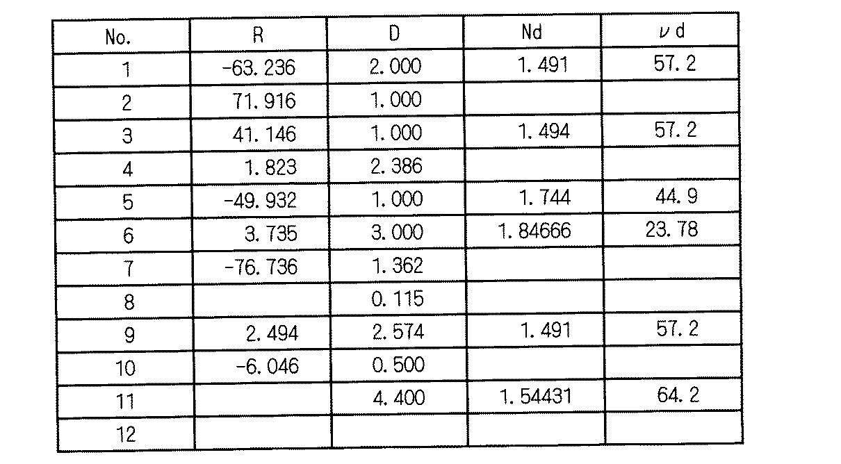
具体的には、本実施形態では、結像レンズ系102は、図1に示すように、第1ないし第4レンズ111〜114を組み合わせて構成されている。第4レンズ114と撮像素子(ここでは、CCD素子)との間には、赤外カットフィルタ、光学ローパスフィルタ及び撮像素子用のカバーガラスからなる複合部材115が備えられている。第2レンズ112と第3レンズ113との間には絞り116が介装されている。第1レンズ111は、物体側のレンズ面(3)が凸面で像側のレンズ面(4)が凹面となっている。第2レンズ112は、2つのレンズ121,122を貼り合わせて構成されており、物体側のレンズ面(5)が凹面で像側のレンズ面(7)が凸面となっており、レンズ121,122の境界面によって構成されるレンズ面(6)が像側から見て凹面となっている。第3レンズ113は、2つのレンズ123,124を貼り合わせて構成されており、物体側及び像側のレンズ面(9,11)が凸面となっており、レンズ123,124の境界面によって構成されるレンズ面(10)が像側から見て凹面となっている。第4レンズ114は、物体側及び像側のレンズ面(12,13)が凸面となっている。コンバータレンズ103は、物体側のレンズ面(1)が凸面で像側のレンズ面(2)が凹面となっている。複合部材115の物体側及び像側の表面(14,15)は平面となっている。なお、図1及び下記の表1において、絞り116に符号8を付与している。
【0016】
下記の表1は、図1の撮像レンズ101の各光学機能要素の具体的構成を示すものである。表1中の最左欄の「1」〜「15」は図1中の光学機能要素に対応しており、「R」は対応する各レンズ面の曲率半径(又は近軸曲率半径)[mm]を示し、「D」は対応する光学要素間の間隔[mm]を示している。「Nd」は対応するレンズのd線に対する屈折率を示し、例えば表中の値「1.491」はコンバータレンズ103の屈折率を示し、値「1.72916」、「1.84666」は第2レンズ112のレンズ121,122の屈折率をそれぞれ示す。また、「νd」は同様に対応するレンズのアッベ数を示す。なお、表1では、複合部材115の表面(14,15)及び絞り116(8)の曲率半径Rの欄を便宜上空欄としている。
【0017】
【表1】
また、本実施形態では、コンバータレンズ103の両レンズ面(1,2)、結像レンズ系101の第1レンズ111のレンズ面(4)、及び第4レンズ114のレンズ面(12)が非球面とされている(他のレンズ面は球面である)。下記の表2は、これらのレンズ面(1,2,4,12)の非球面形状を決定する各設定パラメータの値を示すものであり、下記の数1に代入して非球面形状の決定が行われる。
【0019】
【表2】
【数1】
上記数1において、「r」は近軸曲率半径であり、各レンズ面に対応する表1中のRの値が代入される。「K」は円錐定数であり、「A4,A6,A8,A10,・・・」は高次の非球面係数である。また、表2中の円錐定数及び非球面係数の表記における「Eとそれに続く数字」は10の累乗を表しており、例えば「E+01」は10の1乗を表し、「E−04」は10のマイナス4乗を表している。
【0022】
また、本実施形態では、撮像レンズ101全系の焦点距離f0[mm]及び画角、結像レンズ系102の焦点距離f1[mm]、Fナンバー及び画角は、以下の表3のように設定されている。
【0023】
【表3】
図2(a)ないし図2(c)は結像レンズ系102の球面収差、非点収差及び歪曲収差の収差図であり、図3は結像レンズ系102の横収差図である。なお、図2(b)の非点収差図における「M」はメリディオナルを示し、「S」はサジタルを示している(以下の非点収差図においても同様)。また、図4(a)ないし図4(c)は撮像レンズ101全系の球面収差、非点収差及び歪曲収差の収差図であり、図5は撮像レンズ101全系の横収差図である。これらの収差図より、コンバータレンズ103を使用することによる収差特性の劣化が抑制されていることが分かる。
【0025】
以上のように、本実施形態に係るコンバータレンズ103は、単一のレンズによって構成されているため、コンバータレンズ103及び撮像レンズ101の構成の簡単化、コンパクト化及び軽量化が図れる。
【0026】
また、コンバータレンズ103は、その物体側のレンズ面が凸又は凹面で、その像側のレンズ面が凹面であり(本実施形態では、物体側が凸で像側が凹)、その物体側及び像側のうちの少なくともいずれか一方の面が非球面(本実施形態では、両側のレンズ面が非球面)となっているため、コンバータレンズ103を使用することによる収差特性の劣化を抑制しつつ、画角の変換倍率を大きくすることができる。
【0027】
さらに、撮像レンズ101全系の焦点距離f0と、結像レンズ系102の焦点距離f1とが、0.5<f0/f1<1.5の関係を満たすように設定することにより(本実施形態では、f0/f1=1.009と設定されている)、コンバータレンズ103を使用することによる収差特性の劣化を抑制しつつ、コンバータレンズ103による画角の変換倍率を容易に大きくすることができる。
【0028】
また、本実施形態に係るコンバータレンズ103を既存の結像レンズ系102に組み合わせることにより、広角撮像に適した撮像レンズ101を容易に構成することができる。
【0029】
<第2実施形態>
図6は、本発明の第2実施形態に係る撮像レンズの構成を示す図である。この撮像レンズ201は、図6に示すように、結像レンズ系202とコンバータレンズ203とを備えている。
【0030】
結像レンズ系202は、第1ないし第5レンズ211〜215を組み合わせて構成されている。第5レンズ215と撮像素子との間には、前述の複合部材115と同様な構成の複合部材216が備えられている。第3レンズ213と第4レンズ214との間には絞り217が介装されている。第1レンズ211は、物体側のレンズ面(3)が平面で像側のレンズ面(4)が凹面となっている。第2レンズ212は、物体側のレンズ面(5)が凸面で像側のレンズ面(6)が凹面となっている。第3レンズ213は、物体側のレンズ面(7)が凸面で像側のレンズ面(8)が凸面となっている。第4レンズ214は、2つのレンズ221,222を貼り合わせて構成されており、物体側のレンズ面(10)が凹面で像側のレンズ面(12)が凸面となっており、レンズ221,222の境界面によって構成されるレンズ面(11)が像側から見て凹面となっている。第5レンズ215は、物体側及び像側のレンズ面(13,14)が凸面となっている。コンバータレンズ203の物体側のレンズ面(1)は、その中央部が凸型で、周辺部が凹型の非球面形状を有しており、像側のレンズ面(2)は凹面となっている。複合部材216の物体側及び像側の表面(15,16)は平面となっている。なお、図6及び下記の表4において、絞り217に符号9を付与している。
【0031】
下記の表4は、図6の撮像レンズ201の各光学機能要素の具体的構成を示すものであり、表4の記載様式等は上記表1と同様である。
【0032】
【表4】
また、本実施形態では、コンバータレンズ203の両レンズ面(1,2)が非球面とされている(結像レンズ系202の各レンズ面は球面である)。レンズ面(1,2)の非球面形状は、下記の表5に記載の条件により決定される。
【0034】
【表5】
また、本実施形態では、撮像レンズ201全系の焦点距離f0[mm]及び画角、結像レンズ系202の焦点距離f1[mm]、Fナンバー及び画角は、以下の表6のように設定されている。
【0036】
【表6】
図7(a)ないし図7(c)は結像レンズ系202の球面収差、非点収差及び歪曲収差の収差図であり、図8は結像レンズ系202の横収差図である。また、図9(a)ないし図9(c)は撮像レンズ201全系の球面収差、非点収差及び歪曲収差の収差図であり、図10は撮像レンズ201全系の横収差図である。これらの収差図より、コンバータレンズ203を使用することによる収差特性の劣化が抑制されていることが分かる。
【0038】
<第3実施形態>
図11は、本発明の第3実施形態に係る撮像レンズの構成を示す図である。この撮像レンズ301は、図11に示すように、結像レンズ系302とコンバータレンズ303とを備えている。
【0039】
結像レンズ系302は、第1ないし第3レンズ311〜313を組み合わせて構成されている。第3レンズ313と撮像素子との間には、前述の複合部材115と同様な構成の複合部材314が備えられている。第2レンズ312と第3レンズ313との間には絞り315が介装されている。第1レンズ311は、物体側のレンズ面(3)が凸面で像側のレンズ面(4)が凹面となっている。第2レンズ312は、2つのレンズ321,322を貼り合わせて構成されており、物体側及び像側のレンズ面(5,7)が凹面となっており、レンズ321,322の境界面によって構成されるレンズ面(6)が像側から見て凹面となっている。第3レンズ313は、物体側のレンズ面(9)が凸面で像側のレンズ面(10)が凸面となっている。コンバータレンズ303は、物体側及び像側のレンズ面(1,2)が凹面となっている。複合部材314の物体側及び像側の表面(11,12)は平面となっている。なお、図11及び下記の表7において、絞り315に符号8を付与している。
【0040】
下記の表4は、図11の撮像レンズ301の各光学機能要素の具体的構成を示すものであり、表7の記載様式等は上記表1と同様である。
【0041】
【表7】
また、本実施形態では、コンバータレンズ303の両レンズ面(1,2)、結像レンズ系302のレンズ面(4,9,10)が非球面とされている(他のレンズ面は球面である)。レンズ面(1,2,4,9,10)の非球面形状は、下記の表8に記載の条件により決定される。
【0043】
【表8】
また、本実施形態では、撮像レンズ301全系の焦点距離f0[mm]及び画角、結像レンズ系302の焦点距離f1[mm]、Fナンバー及び画角は、以下の表9のように設定されている。
【0045】
【表9】
図12(a)ないし図12(c)は結像レンズ系302の球面収差、非点収差及び歪曲収差の収差図であり、図13は結像レンズ系302の横収差図である。また、図14(a)ないし図14(c)は撮像レンズ301全系の球面収差、非点収差及び歪曲収差の収差図であり、図15は撮像レンズ301全系の横収差図である。これらの収差図より、コンバータレンズ303を使用することによる収差特性の劣化が抑制されていることが分かる。
【0047】
<第4実施形態>
図16は本発明の第4実施形態に係る車載カメラ装置の横断面図であり、図17はその車載カメラ装置の縦断面図である。この車載カメラ装置1は、前述の第1ないし第3実施形態に係る撮像レンズ101,201,301のうちのいずれかを用いて構成されている。なお、本実施形態では、一例として撮像レンズ101が用いられている。
【0048】
具体的には、車載カメラ装置1は、図16及び図17に示すように、遮光性及び防水性を有するケース13内に、カメラユニット15と、それぞれカメラユニット15の正面側に配置されたコンバータレンズ103及び左右一対のプリズム(反射手段)17,19とを収容配設して構成される。ここで、図17に示される構成要素のうち、カメラユニット15の結像レンズ系102、及びコンバータレンズ103によって撮像レンズ101が構成されている。
【0049】
このような車載カメラ装置1は、図18及び図19に示すように、車両前端部(例えば、フロントグリル部)の中央に設置され、車両前方側における左右の撮像領域A1,A2の撮像と、車両前端部の斜め下方の撮像領域A3の撮像とを同時に行うようになっている。なお、変形例として、車載カメラ装置1を車両後端部に設置し、車両後方側における左右の撮像領域及び斜め下方向の撮像領域を撮像するようにしてもよい。
【0050】
ケース13は、密閉状の箱状に形成されている。このケース13には、左右の撮像領域A1,A2及び斜め下方の撮像領域A3を撮像するための透明性部材による透明窓13L,13R,13Fが設けられている。
【0051】
カメラユニット15は、そのホルダ内に、結像レンズ系102と、CCD素子等の撮像素子31と、撮像素子31の駆動回路等の処理回路33とを収容配設して構成される。
【0052】
結像レンズ系102は、プリズム17,19及びコンバータレンズ103によって導入される撮像領域A1〜A3からの光を取り込み、撮像領域A1〜A3の像を撮像素子31の撮像面上に結像する。撮像素子31は、その撮像面の垂直中心軸P1が結像レンズ系102のレンズ中心軸(光軸)P2に重なる位置から上方に所定距離だけ平行移動された位置に位置するように配設されている。これによって、撮像素子31によって撮像される視野範囲が下方側に拡大されている。
【0053】
コンバータレンズ103は結像レンズ系102の垂直画角の下側領域に配置され、プリズム17,19は結像レンズ系102の垂直画角の上側領域に配置される。すなわち、コンバータレンズ103は、カメラ装置3の複数の視野方向のうちの一部の視野方向(ここでは、前方斜め下方の撮像領域A3)に対応する結像レンズ系102の画角の一部領域だけを占めるように配置され、プリズム17,19は、カメラ装置3の複数の視野方向のうちの残りの視野方向(ここでは、左右の撮像領域A1,A2)に対応する結像レンズ系102の画角の残部領域だけを占めるように配置される。
【0054】
これに対応して、コンバータレンズ103は、結像レンズ系102の垂直画角の上側領域に重複しないように、その上側領域に対応する部分(略上半分の部分)が切り取られた構成を有している。そして、このコンバータレンズ103が結像レンズ系102の垂直画角の下側領域に配置されることで、カメラ装置3の前方斜め下側の視野方向の視野範囲(結像レンズ系102の垂直画角の下側領域に対応する範囲)が、その左右両側及び下側に拡大された広視野となる。
【0055】
左右一対のプリズム17,19は、互いに鏡像対称となる略三角柱形に形成される。そして、左(右)のプリズム17(19)に関しては、その左(右)のプリズム側面17L(19R)及びそのプリズム後面17B(19B)が透過面に保たれ、その右(左)のプリズム側面17R(19L)上には、その内面が反射面(鏡面)と成るように、図示しないアルミ等の金属層が蒸着された上にその蒸着面を被覆するように更に黒色塗料による保護膜(図示省略)が形成される。
【0056】
これら各プリズム17,19は、左(右)のプリズム17(19)に関しては、その頂角が前側に向けられ、その左(右)のプリズム側面17L(19R)がケース13の左(右)の透明窓13L(13R)に対面され、そのプリズム後面17B(19B)が結像レンズ系102に対面されて配置される。そして、これら各プリズム17,19は、結像レンズ系102の正面側にて、互いに結像レンズ系102の左右2等分面に面対称に配置され、ともに鉛直姿勢に保たれて配置され、ともに結像レンズ系102の垂直画角の上側領域内に収まるように、それらの下端部が斜めにカットされている。
【0057】
次に、このカメラ装置3の撮像原理を説明する。
【0058】
車両前端部における斜め下方の撮像領域A3の広角な範囲からの光は、図17に示すように、ケース13の透明窓13Fを透過して、透明窓13Fに組み込まれたコンバータレンズ103により屈折されて結像レンズ系102側に導光され、結像レンズ系102の垂直画角の下側領域を通って直接に結像レンズ系102に入射して、結像レンズ系102により集光されて撮像素子31の撮像面の第1の領域に結像する。これにより、車両の前方斜め下方の撮像領域A3の死角が撮像素子31により広角に撮像される。
【0059】
これと同時に、車両前方側における左右の撮像領域A1,A2の非広角な範囲からの光は、図16に示すように、ケース13の透明窓13L(13R)を透過して左(右)のプリズム17(19)に於ける左(右)のプリズム側面17L(19R)に入射し、左(右)のプリズム17(19)内で、その右(左)のプリズム側面17R(19L)で内面反射し、次いでその左(右)のプリズム側面17L(19R)で内面反射して計2回内面反転されて、そのプリズム後面17B(19B)から射出された後、結像レンズ系102の垂直画角の上側領域を通って結像レンズ系102に入射して、結像レンズ系102により集光されて撮像素子31の撮像面31aの第2の領域(前記第1の領域と重複しない領域)に結像する。これにより車両の前方左右両側方向の死角が撮像素子31により非広角に撮像される。すなわち車両の前方左右両側方向の撮像画像に映る接近物体が大きく映される。
【0060】
このようにして、撮像素子31により、車両の前方斜め下側方向の死角については広角に、車両の前方左右両側方向の死角については非広角に、それぞれ同時に撮像される。撮像素子31によって撮像された撮像領域A1〜A3の撮像画像は、車室内に備えられた図示しない表示装置によって表示される。
【0061】
以上のように、本実施形態に係る車載カメラ装置1によれば、撮像視野内のコンバータレンズ103に対応した領域(A3)と対応しない領域(A1,A2)とを、画角を異ならせつつ同時に撮像することができるため、車両周辺の撮像領域A1〜A3の特性に柔軟に対応して撮像を行うことができ、車両周辺の良好な撮像画像を提供することができる。
【0062】
また、車両前端部における斜め下方の撮像領域A3がコンバータレンズ103を介して撮像されるため、カメラ装置1からの距離に比して広範囲な斜め下方の撮像領域A3を容易に撮像できるとともに、左右の撮像領域A1,A2についてはコンバータレンズ103を介さずに撮像されるため、左右の撮像領域A1,A2内の景色を比較的大きな画像サイズで撮像することができる。
【0063】
【発明の効果】
請求項1に記載の発明によれば、単一のレンズによって構成されているため、コンバータレンズの構成の簡単化、コンパクト化及び軽量化が図れる。
【0064】
また、コンバータレンズは、その物体側の面が凸又は凹面で、その像側の面が凹面であり、その物体側及び像側のうちの少なくともいずれか一方の面が非球面となっているため、コンバータレンズを使用することによる収差特性の劣化を抑制しつつ、画角の変換倍率を大きくすることができる。
【0065】
さらに、結像レンズ系とコンバータレンズとのレンズ全系の焦点距離f0と、結像レンズ系の焦点距離f1とが、0.5<f0/f1<1.5の関係を満たすように設定することにより、コンバータレンズを使用することによる収差特性の劣化を抑制しつつ、コンバータレンズによる画角の変換倍率を容易に大きくすることができる。
【0066】
また、本発明に係るコンバータレンズを既存の結像レンズ系に組み合わせることにより、広角撮像に適した撮像レンズを容易に構成することができる。
【0067】
またコンバータレンズは、結像レンズ系の撮像視野のうちの一部の領域のみを覆うように、その一部分が切り取られたような構成を有するので、結像レンズの撮像視野のうちのコンバータレンズを介さずに撮像を行う領域と、コンバータレンズを介して撮像を行う領域とで画角を異ならせることができる。
【0068】
また、撮像視野内のコンバータレンズに対応した領域と対応しない領域とを、画角を異ならせつつ同時に撮像することができるため、車両周辺の撮像領域の特性に柔軟に対応して撮像を行うことができ、車両周辺の良好な撮像画像を提供することができる。
【0069】
また、車両前端部又は後端部の斜め下方の撮像領域がコンバータレンズを介して撮像されるため、カメラ装置からの距離に比して広範な斜め下方の撮像領域を容易に撮像できるとともに、左右の撮像領域についてはコンバータレンズを介さずに撮像されるため、左右の撮像領域内の景色を比較的大きな画像サイズで撮像することができる。
【図面の簡単な説明】
【図1】本発明の第1実施形態に係る撮像レンズの構成を示す図である。
【図2】図2(a)ないし図2(c)は図1の結像レンズ系の球面収差、非点収差及び歪曲収差の収差図である。
【図3】図1の結像レンズ系の横収差図である。
【図4】図4(a)ないし図4(c)は図1の撮像レンズ全系の球面収差、非点収差及び歪曲収差の収差図である。
【図5】図1の撮像レンズ全系の横収差図である。
【図6】本発明の第2実施形態に係る撮像レンズの構成を示す図である。
【図7】図7(a)ないし図7(c)は図6の結像レンズ系の球面収差、非点収差及び歪曲収差の収差図である。
【図8】図6の結像レンズ系の横収差図である。
【図9】図9(a)ないし図9(c)は図6の撮像レンズ全系の球面収差、非点収差及び歪曲収差の収差図である。
【図10】図6の撮像レンズ全系の横収差図である。
【図11】本発明の第3実施形態に係る撮像レンズの構成を示す図である。
【図12】図12(a)ないし図12(c)は図11の結像レンズ系の球面収差、非点収差及び歪曲収差の収差図である。
【図13】図11の結像レンズ系の横収差図である。
【図14】図14(a)ないし図14(c)は図11の撮像レンズ全系の球面収差、非点収差及び歪曲収差の収差図である。
【図15】図11の撮像レンズ全系の横収差図である。
【図16】本発明の第4実施形態に係る車載カメラ装置の横断面図である。
【図17】図16の車載カメラ装置の縦断面図である。
【図18】図16の車載カメラの車両への設置形態を示す図である。
【図19】図16の車載カメラの車両への設置形態を示す図である。
【符号の説明】
1 車載カメラ装置
17,19 プリズム
31 撮像素子
101,201,301 撮像レンズ
102,202,203 結像レンズ系
103,203,303 コンバータレンズ[0001]
The present invention is a converter lens. and Imaging lens The It is related with the used vehicle-mounted camera apparatus.
[0002]
[Prior art]
In this type of conventional imaging lens, as a converter lens to be combined with the imaging lens system, one that constitutes an afocal system is generally used in order to prevent the focus position and the like from being moved by mounting the converter lens. In this case, the converter lens is configured by combining a plurality of lenses to form an afocal system.
[0003]
In addition, as a related technique of this invention, there exists a thing of
[0004]
[Patent Document 1]
JP 2002-72085 A
[Patent Document 2]
Japanese Patent Laid-Open No. 2002-365531
[0005]
[Problems to be solved by the invention]
However, in the above-described conventional technology, since the converter lens is configured by a plurality of lenses, the configuration of the converter lens becomes complicated, and the size and weight increase.
[0006]
Therefore, the present invention can simplify, compact, and reduce the configuration of the converter lens while suppressing deterioration of aberration characteristics. Car An object of the present invention is to provide a mounted camera device.
[0007]
[Means for Solving the Problems]
The technical means for achieving the object is an in-vehicle camera that is arranged in a vehicle and images the periphery of the vehicle, and the in-vehicle camera device forms an image of the imaging object on a predetermined image plane. An image lens system, a converter lens disposed on the object side of the imaging lens system, and converting the angle-of-view characteristics of the imaging lens system into characteristics suitable for wide-angle imaging, and the imaging lens system An image pickup device that picks up an image formed by the image sensor, wherein the converter lens has a convex or concave surface on the object side, and a concave surface on the image side. A configuration in which at least one of the surfaces is constituted by a single lens having an aspherical surface, and a part of the imaging lens system is cut out so as to cover only a part of the imaging field of view. And the focal length f0 of the entire lens system of the imaging lens system and the converter lens and the focal length f1 of the imaging lens system have a relationship of 0.5 <f0 / f1 <1.5. Fulfill.
[0011]
further ,in front The in-vehicle camera device is installed at the front end portion or the rear end portion of the vehicle, images the left and right imaging regions on the vehicle front side or the rear side, and the imaging region obliquely below the vehicle front end portion or the rear end portion, and Further includes reflecting means for reflecting light from the left and right imaging areas and introducing the reflected light into the imaging lens system, and a part of the imaging field of the imaging lens system is the left and right imaging areas. The other area is assigned to the imaging area obliquely below, and the converter lens of the imaging lens is arranged corresponding to the other area in the imaging field of view.
[0012]
DETAILED DESCRIPTION OF THE INVENTION
<First Embodiment>
FIG. 1 is a diagram showing a configuration of an imaging lens according to the first embodiment of the present invention. As shown in FIG. 1, the
[0013]
In this embodiment, the
0.5 <f0 / f1 <1.5
It is set to satisfy the relationship.
[0014]
Here, the upper limit value (1.5) in the above relationship is an effective field angle conversion by the
[0015]
Specifically, in the present embodiment, the
[0016]
Table 1 below shows a specific configuration of each optical functional element of the
[0017]
[Table 1]
In the present embodiment, both the lens surfaces (1, 2) of the
[0019]
[Table 2]
[Expression 1]
In the
[0022]
In this embodiment, the focal length f0 [mm] and the angle of view of the
[0023]
[Table 3]
2A to 2C are aberration diagrams of spherical aberration, astigmatism, and distortion of the
[0025]
As described above, since the
[0026]
The
[0027]
Further, the focal length f0 of the
[0028]
Further, by combining the
[0029]
<Second Embodiment>
FIG. 6 is a diagram illustrating a configuration of an imaging lens according to the second embodiment of the present invention. The
[0030]
The
[0031]
Table 4 below shows a specific configuration of each optical functional element of the
[0032]
[Table 4]
In the present embodiment, both lens surfaces (1, 2) of the
[0034]
[Table 5]
In this embodiment, the focal length f0 [mm] and the angle of view of the
[0036]
[Table 6]
7A to 7C are aberration diagrams of spherical aberration, astigmatism, and distortion of the
[0038]
<Third Embodiment>
FIG. 11 is a diagram illustrating a configuration of an imaging lens according to the third embodiment of the present invention. The
[0039]
The
[0040]
Table 4 below shows a specific configuration of each optical functional element of the
[0041]
[Table 7]
In this embodiment, both the lens surfaces (1, 2) of the
[0043]
[Table 8]
In this embodiment, the focal length f0 [mm] and the angle of view of the
[0045]
[Table 9]
12A to 12C are aberration diagrams of spherical aberration, astigmatism, and distortion of the
[0047]
<Fourth embodiment>
FIG. 16 is a cross-sectional view of an in-vehicle camera device according to a fourth embodiment of the present invention, and FIG. 17 is a vertical cross-sectional view of the in-vehicle camera device. The in-
[0048]
Specifically, as shown in FIGS. 16 and 17, the in-
[0049]
As shown in FIGS. 18 and 19, such an in-
[0050]
The
[0051]
The
[0052]
The
[0053]
The
[0054]
Correspondingly, the
[0055]
The pair of left and
[0056]
With respect to the left (right) prism 17 (19), each of the
[0057]
Next, the imaging principle of the camera device 3 will be described.
[0058]
As shown in FIG. 17, light from a wide-angle range of the imaging area A3 obliquely below the front end of the vehicle passes through the
[0059]
At the same time, the light from the non-wide-angle range of the left and right imaging areas A1 and A2 on the front side of the vehicle is transmitted through the
[0060]
In this manner, the
[0061]
As described above, according to the in-
[0062]
In addition, since the imaging area A3 obliquely below the front end of the vehicle is imaged through the
[0063]
【The invention's effect】
[0064]
The converter lens has a convex or concave surface on the object side, a concave surface on the image side, and an aspheric surface on at least one of the object side and the image side. Further, it is possible to increase the conversion magnification of the angle of view while suppressing the deterioration of the aberration characteristics due to the use of the converter lens.
[0065]
Further, the focal length f0 of the entire lens system of the imaging lens system and the converter lens and the focal length f1 of the imaging lens system are set so as to satisfy the relationship of 0.5 <f0 / f1 <1.5. As a result, it is possible to easily increase the conversion angle of the angle of view by the converter lens while suppressing the deterioration of the aberration characteristics due to the use of the converter lens.
[0066]
In addition, an imaging lens suitable for wide-angle imaging can be easily configured by combining the converter lens according to the present invention with an existing imaging lens system.
[0067]
Further, the converter lens has a configuration in which a part thereof is cut out so as to cover only a part of the imaging field of the imaging lens system. The angle of view can be made different between a region in which imaging is performed without using the converter lens and a region in which imaging is performed through the converter lens.
[0068]
Also, Since the area corresponding to the converter lens in the imaging field and the area not corresponding can be imaged simultaneously with different angles of view, imaging can be performed flexibly corresponding to the characteristics of the imaging area around the vehicle. It is possible to provide a good captured image around the vehicle.
[0069]
Also, Since the imaging area obliquely below the front or rear end of the vehicle is imaged via the converter lens, it is possible to easily image a wide imaging area obliquely below the distance from the camera device, and to capture the left and right images. Since the area is imaged without passing through the converter lens, the scenery in the left and right imaging areas can be imaged with a relatively large image size.
[Brief description of the drawings]
FIG. 1 is a diagram illustrating a configuration of an imaging lens according to a first embodiment of the present invention.
2A to 2C are aberration diagrams of spherical aberration, astigmatism, and distortion of the imaging lens system of FIG.
3 is a transverse aberration diagram of the imaging lens system of FIG. 1. FIG.
FIGS. 4A to 4C are aberration diagrams of spherical aberration, astigmatism, and distortion of the entire imaging lens system of FIG.
5 is a lateral aberration diagram of the entire imaging lens system of FIG. 1. FIG.
FIG. 6 is a diagram illustrating a configuration of an imaging lens according to a second embodiment of the present invention.
FIGS. 7A to 7C are aberration diagrams of spherical aberration, astigmatism, and distortion of the imaging lens system of FIG.
8 is a lateral aberration diagram of the imaging lens system of FIG. 6. FIG.
9A to 9C are aberration diagrams of spherical aberration, astigmatism, and distortion of the entire imaging lens system of FIG.
10 is a transverse aberration diagram for the entire imaging lens system shown in FIG. 6. FIG.
FIG. 11 is a diagram illustrating a configuration of an imaging lens according to a third embodiment of the present invention.
FIGS. 12A to 12C are aberration diagrams of spherical aberration, astigmatism, and distortion of the imaging lens system of FIG.
13 is a lateral aberration diagram of the imaging lens system of FIG. 11. FIG.
14A to 14C are aberration diagrams of the spherical aberration, astigmatism, and distortion of the entire imaging lens system shown in FIG.
15 is a transverse aberration diagram for the entire imaging lens system shown in FIG. 11. FIG.
FIG. 16 is a cross-sectional view of an in-vehicle camera device according to a fourth embodiment of the present invention.
17 is a longitudinal sectional view of the in-vehicle camera device of FIG.
FIG. 18 is a diagram showing an installation mode of the in-vehicle camera of FIG.
FIG. 19 is a diagram showing an installation mode of the in-vehicle camera of FIG.
[Explanation of symbols]
1 In-vehicle camera device
17,19 Prism
31 Image sensor
101, 201, 301 Imaging lens
102, 202, 203 Imaging lens system
103, 203, 303 Converter lens
Claims (1)
前記車載カメラ装置は、
撮像対象物の像を所定の像面に結像させる結像レンズ系と、
前記結像レンズ系の物体側に配置され、前記結像レンズ系の画角特性を広角撮影に適した特性に変換するコンバータレンズと、
前記結像レンズ系によって結像された像を撮像する撮像素子と、
を備え、
前記コンバータレンズは、
その物体側の面が凸又は凹面で、その像側の面が凹面であり、その物体側及び像側のうちの少なくともいずれか一方の面が非球面である単一のレンズにより構成され、前記結像レンズ系の撮像視野のうちの一部の領域のみを覆うように、その一部分が切り取られたような構成を有し、
前記結像レンズ系と前記コンバータレンズとのレンズ全系の焦点距離f0と、前記結像レンズ系の焦点距離f1とが、
0.5<f0/f1<1.5
の関係を満たし、
前記車載カメラ装置は、車両前端部又は後端部に設置され、車両前方側又は後方側における左右の撮像領域及び車両前端部又は後端部の斜め下方の撮像領域を撮像し、
前記車載カメラ装置は、
前記左右の撮像領域から光を反射して前記結像レンズ系に導入する反射手段をさらに備え、
前記結像レンズ系の前記撮像視野のうちの一部の領域が前記左右の撮像領域に割り当てられ、他の領域が前記斜め下方の撮像領域に割り当てられ、前記コンバータレンズが、前記撮像視野のうちの前記他の領域に対応して配置されている、車載カメラ装置。An in-vehicle camera that is arranged in a vehicle and images the periphery of the vehicle,
The in-vehicle camera device is
An imaging lens system for forming an image of the imaging object on a predetermined image plane;
A converter lens that is disposed on the object side of the imaging lens system and converts the angle-of-view characteristics of the imaging lens system into characteristics suitable for wide-angle imaging;
An image sensor that images an image formed by the imaging lens system ;
With
The converter lens is
The object-side surface is convex or concave, the image-side surface is concave, and at least one of the object-side and image-side surfaces is composed of a single lens, A configuration in which a part of the imaging field of the imaging lens system is cut out so as to cover only a part of the imaging field of view,
The focal length f0 of the entire lens system of the imaging lens system and the converter lens, and the focal length f1 of the imaging lens system are:
0.5 <f0 / f1 <1.5
Satisfy the relationship
The in-vehicle camera device is installed at a vehicle front end portion or a rear end portion, images left and right imaging regions on the vehicle front side or rear side, and an imaging region obliquely below the vehicle front end portion or rear end portion,
The in-vehicle camera device is
Reflecting means for reflecting light from the left and right imaging regions and introducing it into the imaging lens system,
A portion of the imaging field of the imaging lens system is assigned to the left and right imaging regions, another region is assigned to the obliquely lower imaging region, and the converter lens is included in the imaging field. The vehicle-mounted camera apparatus arrange | positioned corresponding to the said other area | region.
Priority Applications (1)
| Application Number | Priority Date | Filing Date | Title |
|---|---|---|---|
| JP2003115815A JP4527363B2 (en) | 2003-04-21 | 2003-04-21 | In-vehicle camera device |
Applications Claiming Priority (1)
| Application Number | Priority Date | Filing Date | Title |
|---|---|---|---|
| JP2003115815A JP4527363B2 (en) | 2003-04-21 | 2003-04-21 | In-vehicle camera device |
Publications (3)
| Publication Number | Publication Date |
|---|---|
| JP2004325498A JP2004325498A (en) | 2004-11-18 |
| JP2004325498A5 JP2004325498A5 (en) | 2005-10-27 |
| JP4527363B2 true JP4527363B2 (en) | 2010-08-18 |
Family
ID=33496257
Family Applications (1)
| Application Number | Title | Priority Date | Filing Date |
|---|---|---|---|
| JP2003115815A Expired - Fee Related JP4527363B2 (en) | 2003-04-21 | 2003-04-21 | In-vehicle camera device |
Country Status (1)
| Country | Link |
|---|---|
| JP (1) | JP4527363B2 (en) |
Cited By (2)
| Publication number | Priority date | Publication date | Assignee | Title |
|---|---|---|---|---|
| CN104730691A (en) * | 2013-12-24 | 2015-06-24 | Kolen株式会社 | Photographic Lens Optical System And Photographic Device Using Same |
| JP2018005043A (en) * | 2016-07-05 | 2018-01-11 | キヤノン株式会社 | Wide attachment, and image capturing lens and image capturing device having the same |
Families Citing this family (6)
| Publication number | Priority date | Publication date | Assignee | Title |
|---|---|---|---|---|
| JP2005345577A (en) * | 2004-05-31 | 2005-12-15 | Kyocera Corp | Super wide angle lens |
| JP4908887B2 (en) * | 2006-03-23 | 2012-04-04 | キヤノン株式会社 | Fish eye attachment |
| JP4845121B2 (en) * | 2006-12-25 | 2011-12-28 | 節男 黒木 | Vehicle with visual camera with front fender camera mechanism |
| JP2017125978A (en) * | 2016-01-14 | 2017-07-20 | 株式会社リコー | Imaging optical system and device having the imaging optical system |
| US11150448B2 (en) * | 2016-11-06 | 2021-10-19 | Denso Corporation | Vehicle windshield mounted camera module |
| TWI650592B (en) | 2018-04-18 | 2019-02-11 | 大立光電股份有限公司 | Camera optical lens group, image capturing device and electronic device |
Family Cites Families (6)
| Publication number | Priority date | Publication date | Assignee | Title |
|---|---|---|---|---|
| DE3036070A1 (en) * | 1979-09-28 | 1981-04-16 | Bolex International S.A., Yverdon | Optical system with two zoom ranges - has second lens group for focussing defining one zoom range and front group for second range |
| JP3029139B2 (en) * | 1991-05-29 | 2000-04-04 | キヤノン株式会社 | Rear focus zoom lens |
| JP2684874B2 (en) * | 1991-06-25 | 1997-12-03 | 三菱電機株式会社 | Wire electric discharge machining apparatus and wire electric discharge machining method |
| JP2001094839A (en) * | 1999-09-21 | 2001-04-06 | Inaryo Technica Kk | Wide visual field image pickup device and wide visual field image pickup display device |
| JP3841621B2 (en) * | 2000-07-13 | 2006-11-01 | シャープ株式会社 | Omnidirectional visual sensor |
| JP4513214B2 (en) * | 2001-02-15 | 2010-07-28 | 沖電気工業株式会社 | Wide angle photographing device and camera device using the same |
-
2003
- 2003-04-21 JP JP2003115815A patent/JP4527363B2/en not_active Expired - Fee Related
Cited By (3)
| Publication number | Priority date | Publication date | Assignee | Title |
|---|---|---|---|---|
| CN104730691A (en) * | 2013-12-24 | 2015-06-24 | Kolen株式会社 | Photographic Lens Optical System And Photographic Device Using Same |
| JP2018005043A (en) * | 2016-07-05 | 2018-01-11 | キヤノン株式会社 | Wide attachment, and image capturing lens and image capturing device having the same |
| US10409042B2 (en) | 2016-07-05 | 2019-09-10 | Canon Kabushiki Kaisha | Wide attachment, and image pickup lens and image pickup apparatus including same |
Also Published As
| Publication number | Publication date |
|---|---|
| JP2004325498A (en) | 2004-11-18 |
Similar Documents
| Publication | Publication Date | Title |
|---|---|---|
| JP4509559B2 (en) | Wide-angle imaging optical system, wide-angle imaging device including the same, surveillance imaging device, in-vehicle imaging device, and projection device | |
| JP5143595B2 (en) | Imaging lens and imaging apparatus | |
| JP6643090B2 (en) | Imaging lens and imaging device | |
| JP6811088B2 (en) | Imaging lens and imaging device | |
| JP3485685B2 (en) | Refractive index single lens | |
| JP4864403B2 (en) | Wide-angle lens system and imaging device | |
| JP2019211598A (en) | Image capturing lens and image capturing device | |
| JP4173210B2 (en) | Imaging lens | |
| JP4274602B2 (en) | Objective optical system | |
| WO2017150486A1 (en) | Optical system, imaging device provided with same, and projection device | |
| JP2009031762A (en) | Imaging lens and imaging device | |
| JP6798803B2 (en) | Imaging lens and imaging device | |
| JP2017134235A (en) | Image capturing lens and image capturing device | |
| JP2008233610A (en) | Imaging lens and imaging device equipped with the imaging lens | |
| JP6695995B2 (en) | Imaging lens system and imaging device | |
| JP2009098322A (en) | Imaging lens and imaging apparatus | |
| JP7005207B2 (en) | Optical system, imaging device and projection device equipped with it | |
| CN110023809B (en) | Imaging optical system, lens unit, and imaging device | |
| JPWO2009125522A1 (en) | Imaging lens | |
| JP2017044731A (en) | Imaging lens and imaging apparatus | |
| JP2019090996A (en) | Optical system, imaging device, distance measuring device, and on-vehicle camera system | |
| JP4527363B2 (en) | In-vehicle camera device | |
| JP2019101181A (en) | Imaging device | |
| JP2018189747A (en) | Optical system, imaging apparatus and projection apparatus including the same | |
| JP2017044733A (en) | Imaging lens and imaging apparatus |
Legal Events
| Date | Code | Title | Description |
|---|---|---|---|
| A521 | Request for written amendment filed |
Free format text: JAPANESE INTERMEDIATE CODE: A523 Effective date: 20050901 |
|
| A621 | Written request for application examination |
Free format text: JAPANESE INTERMEDIATE CODE: A621 Effective date: 20050901 |
|
| A131 | Notification of reasons for refusal |
Free format text: JAPANESE INTERMEDIATE CODE: A131 Effective date: 20080924 |
|
| A521 | Request for written amendment filed |
Free format text: JAPANESE INTERMEDIATE CODE: A523 Effective date: 20081121 |
|
| RD04 | Notification of resignation of power of attorney |
Free format text: JAPANESE INTERMEDIATE CODE: A7424 Effective date: 20081121 |
|
| A131 | Notification of reasons for refusal |
Free format text: JAPANESE INTERMEDIATE CODE: A131 Effective date: 20091013 |
|
| A521 | Request for written amendment filed |
Free format text: JAPANESE INTERMEDIATE CODE: A523 Effective date: 20091207 |
|
| A131 | Notification of reasons for refusal |
Free format text: JAPANESE INTERMEDIATE CODE: A131 Effective date: 20100105 |
|
| A521 | Request for written amendment filed |
Free format text: JAPANESE INTERMEDIATE CODE: A523 Effective date: 20100305 |
|
| A711 | Notification of change in applicant |
Free format text: JAPANESE INTERMEDIATE CODE: A711 Effective date: 20100223 |
|
| A521 | Request for written amendment filed |
Free format text: JAPANESE INTERMEDIATE CODE: A821 Effective date: 20100414 |
|
| RD02 | Notification of acceptance of power of attorney |
Free format text: JAPANESE INTERMEDIATE CODE: A7422 Effective date: 20100414 |
|
| A521 | Request for written amendment filed |
Free format text: JAPANESE INTERMEDIATE CODE: A821 Effective date: 20100414 |
|
| A521 | Request for written amendment filed |
Free format text: JAPANESE INTERMEDIATE CODE: A523 Effective date: 20100416 |
|
| TRDD | Decision of grant or rejection written | ||
| A01 | Written decision to grant a patent or to grant a registration (utility model) |
Free format text: JAPANESE INTERMEDIATE CODE: A01 Effective date: 20100525 |
|
| A01 | Written decision to grant a patent or to grant a registration (utility model) |
Free format text: JAPANESE INTERMEDIATE CODE: A01 |
|
| A61 | First payment of annual fees (during grant procedure) |
Free format text: JAPANESE INTERMEDIATE CODE: A61 Effective date: 20100603 |
|
| FPAY | Renewal fee payment (event date is renewal date of database) |
Free format text: PAYMENT UNTIL: 20130611 Year of fee payment: 3 |
|
| R150 | Certificate of patent or registration of utility model |
Free format text: JAPANESE INTERMEDIATE CODE: R150 |
|
| FPAY | Renewal fee payment (event date is renewal date of database) |
Free format text: PAYMENT UNTIL: 20140611 Year of fee payment: 4 |
|
| R250 | Receipt of annual fees |
Free format text: JAPANESE INTERMEDIATE CODE: R250 |
|
| S111 | Request for change of ownership or part of ownership |
Free format text: JAPANESE INTERMEDIATE CODE: R313117 |
|
| R360 | Written notification for declining of transfer of rights |
Free format text: JAPANESE INTERMEDIATE CODE: R360 |
|
| R370 | Written measure of declining of transfer procedure |
Free format text: JAPANESE INTERMEDIATE CODE: R370 |
|
| S531 | Written request for registration of change of domicile |
Free format text: JAPANESE INTERMEDIATE CODE: R313531 |
|
| R350 | Written notification of registration of transfer |
Free format text: JAPANESE INTERMEDIATE CODE: R350 |
|
| S111 | Request for change of ownership or part of ownership |
Free format text: JAPANESE INTERMEDIATE CODE: R313117 |
|
| R350 | Written notification of registration of transfer |
Free format text: JAPANESE INTERMEDIATE CODE: R350 |
|
| R250 | Receipt of annual fees |
Free format text: JAPANESE INTERMEDIATE CODE: R250 |
|
| R250 | Receipt of annual fees |
Free format text: JAPANESE INTERMEDIATE CODE: R250 |
|
| S531 | Written request for registration of change of domicile |
Free format text: JAPANESE INTERMEDIATE CODE: R313531 |
|
| S533 | Written request for registration of change of name |
Free format text: JAPANESE INTERMEDIATE CODE: R313533 |
|
| R350 | Written notification of registration of transfer |
Free format text: JAPANESE INTERMEDIATE CODE: R350 |
|
| LAPS | Cancellation because of no payment of annual fees |