JP4519141B2 - Pneumatic tire - Google Patents
Pneumatic tire Download PDFInfo
- Publication number
- JP4519141B2 JP4519141B2 JP2006547976A JP2006547976A JP4519141B2 JP 4519141 B2 JP4519141 B2 JP 4519141B2 JP 2006547976 A JP2006547976 A JP 2006547976A JP 2006547976 A JP2006547976 A JP 2006547976A JP 4519141 B2 JP4519141 B2 JP 4519141B2
- Authority
- JP
- Japan
- Prior art keywords
- groove
- tread
- region
- shallow
- tire
- Prior art date
- Legal status (The legal status is an assumption and is not a legal conclusion. Google has not performed a legal analysis and makes no representation as to the accuracy of the status listed.)
- Expired - Fee Related
Links
Images


Classifications
-
- B—PERFORMING OPERATIONS; TRANSPORTING
- B60—VEHICLES IN GENERAL
- B60C—VEHICLE TYRES; TYRE INFLATION; TYRE CHANGING; CONNECTING VALVES TO INFLATABLE ELASTIC BODIES IN GENERAL; DEVICES OR ARRANGEMENTS RELATED TO TYRES
- B60C11/00—Tyre tread bands; Tread patterns; Anti-skid inserts
- B60C11/03—Tread patterns
- B60C11/12—Tread patterns characterised by the use of narrow slits or incisions, e.g. sipes
-
- B—PERFORMING OPERATIONS; TRANSPORTING
- B60—VEHICLES IN GENERAL
- B60C—VEHICLE TYRES; TYRE INFLATION; TYRE CHANGING; CONNECTING VALVES TO INFLATABLE ELASTIC BODIES IN GENERAL; DEVICES OR ARRANGEMENTS RELATED TO TYRES
- B60C11/00—Tyre tread bands; Tread patterns; Anti-skid inserts
- B60C11/03—Tread patterns
- B60C11/0302—Tread patterns directional pattern, i.e. with main rolling direction
-
- B—PERFORMING OPERATIONS; TRANSPORTING
- B60—VEHICLES IN GENERAL
- B60C—VEHICLE TYRES; TYRE INFLATION; TYRE CHANGING; CONNECTING VALVES TO INFLATABLE ELASTIC BODIES IN GENERAL; DEVICES OR ARRANGEMENTS RELATED TO TYRES
- B60C11/00—Tyre tread bands; Tread patterns; Anti-skid inserts
- B60C11/03—Tread patterns
- B60C11/12—Tread patterns characterised by the use of narrow slits or incisions, e.g. sipes
- B60C11/1204—Tread patterns characterised by the use of narrow slits or incisions, e.g. sipes with special shape of the sipe
- B60C2011/1213—Tread patterns characterised by the use of narrow slits or incisions, e.g. sipes with special shape of the sipe sinusoidal or zigzag at the tread surface
-
- B—PERFORMING OPERATIONS; TRANSPORTING
- B60—VEHICLES IN GENERAL
- B60C—VEHICLE TYRES; TYRE INFLATION; TYRE CHANGING; CONNECTING VALVES TO INFLATABLE ELASTIC BODIES IN GENERAL; DEVICES OR ARRANGEMENTS RELATED TO TYRES
- B60C11/00—Tyre tread bands; Tread patterns; Anti-skid inserts
- B60C11/03—Tread patterns
- B60C11/12—Tread patterns characterised by the use of narrow slits or incisions, e.g. sipes
- B60C11/1204—Tread patterns characterised by the use of narrow slits or incisions, e.g. sipes with special shape of the sipe
- B60C2011/1231—Tread patterns characterised by the use of narrow slits or incisions, e.g. sipes with special shape of the sipe being shallow, i.e. sipe depth of less than 3 mm
-
- B—PERFORMING OPERATIONS; TRANSPORTING
- B60—VEHICLES IN GENERAL
- B60C—VEHICLE TYRES; TYRE INFLATION; TYRE CHANGING; CONNECTING VALVES TO INFLATABLE ELASTIC BODIES IN GENERAL; DEVICES OR ARRANGEMENTS RELATED TO TYRES
- B60C11/00—Tyre tread bands; Tread patterns; Anti-skid inserts
- B60C11/03—Tread patterns
- B60C11/12—Tread patterns characterised by the use of narrow slits or incisions, e.g. sipes
- B60C11/1236—Tread patterns characterised by the use of narrow slits or incisions, e.g. sipes with special arrangements in the tread pattern
- B60C2011/1245—Tread patterns characterised by the use of narrow slits or incisions, e.g. sipes with special arrangements in the tread pattern being arranged in crossing relation, e.g. sipe mesh
-
- B—PERFORMING OPERATIONS; TRANSPORTING
- B60—VEHICLES IN GENERAL
- B60C—VEHICLE TYRES; TYRE INFLATION; TYRE CHANGING; CONNECTING VALVES TO INFLATABLE ELASTIC BODIES IN GENERAL; DEVICES OR ARRANGEMENTS RELATED TO TYRES
- B60C11/00—Tyre tread bands; Tread patterns; Anti-skid inserts
- B60C11/03—Tread patterns
- B60C11/12—Tread patterns characterised by the use of narrow slits or incisions, e.g. sipes
- B60C11/1272—Width of the sipe
- B60C2011/1277—Width of the sipe being narrow, i.e. less than 0.3 mm
-
- Y—GENERAL TAGGING OF NEW TECHNOLOGICAL DEVELOPMENTS; GENERAL TAGGING OF CROSS-SECTIONAL TECHNOLOGIES SPANNING OVER SEVERAL SECTIONS OF THE IPC; TECHNICAL SUBJECTS COVERED BY FORMER USPC CROSS-REFERENCE ART COLLECTIONS [XRACs] AND DIGESTS
- Y10—TECHNICAL SUBJECTS COVERED BY FORMER USPC
- Y10S—TECHNICAL SUBJECTS COVERED BY FORMER USPC CROSS-REFERENCE ART COLLECTIONS [XRACs] AND DIGESTS
- Y10S152/00—Resilient tires and wheels
- Y10S152/03—Slits in threads
Landscapes
- Engineering & Computer Science (AREA)
- Mechanical Engineering (AREA)
- Tires In General (AREA)
Description
本発明は、トレッド面に複数の周溝で区画された複数の陸部を有する空気入りに関し、さらに詳しくは、タイヤ使用初期での性能を向上させた空気入りタイヤに関する。 The present invention relates to a pneumatic tire having a plurality of land portions defined on a tread surface by a plurality of circumferential grooves, and more particularly to a pneumatic tire having improved performance at the initial use of the tire.
氷雪路面やウエット路面等での性能を向上させたタイヤとして、いわゆるスタッドレスタイヤがある。スタッドレスタイヤには、種々の充填剤を配合して、氷表面のエッジ効果を得るようにしたものや、発泡ゴムを使用して、使用期間中の発泡層による吸水・エッジ効果を得るようにしたもの等がある。 There is a so-called studless tire as a tire with improved performance on an icy and snowy road surface or a wet road surface. Studless tires are blended with various fillers to obtain an edge effect on the ice surface, and foam rubber is used to obtain the water absorption / edge effect of the foam layer during the period of use. There are things.
しかし、一般にゴムは、加硫硬化された場合に金型と直接接触するタイヤ表面に、上記の充填剤や発泡層が露出せず、タイヤ表面に皮膜が形成されてしまう傾向にある。その結果、タイヤの使用初期においては、充填剤や発泡層の効果が発揮されない(若しくは、その効果が小さい)ことになる。 However, in general, when rubber is vulcanized and cured, the filler and the foamed layer are not exposed on the surface of the tire that is in direct contact with the mold, and a film tends to be formed on the surface of the tire. As a result, in the initial use of the tire, the effect of the filler and the foam layer is not exhibited (or the effect is small).
これに対し、たとえば特許文献1や特許文献2には、トレッド表面に細溝を形成することで、摩耗初期における制駆動性能を向上させた氷雪路用空気入りタイヤが記載されている。また、特許文献3には、トレッドの接地陸部にタイヤ周方向と0°〜40°の角度をなす浅溝をタイヤ幅方向に並べて配置した空気入りタイヤが記載されている。
しかしながら、空気入りタイヤの実際の使用状況では、使用初期における更なる性能向上が求められている。 However, in an actual use situation of a pneumatic tire, further performance improvement in the initial use is required.
本発明は上記事実を考慮し、使用初期での更なる性能向上を図ることが可能な空気入りタイヤを得ることを課題とする。 In view of the above facts, an object of the present invention is to obtain a pneumatic tire capable of further improving performance in the initial use.
上記課題を解決するために、本発明の第1の態様の空気入りタイヤは、トレッド面に複数の主溝で区画された複数の陸部を有し、タイヤ幅方向に延びる少なくとも1つのサイプによって前記陸部が分割されてサブブロックが形成された空気入りタイヤにおいて、前記複数の主溝の少なくとも1本は主たる排水溝としての排水主溝であり、前記陸部に、前記サイプよりも浅い浅溝が複数形成され、前記トレッド面のタイヤ幅方向の端部側に配置されるトレッド端部領域、及び、前記陸部の前記排水主溝に隣接する陸端部領域の少なくとも一方の領域において、タイヤ幅方向の断面での単位領域あたりの前記浅溝の断面積の合計が、他の領域における前記単位領域あたりの前記浅溝の断面積の合計よりも大きいことを特徴としている。 In order to solve the above-described problem, the pneumatic tire according to the first aspect of the present invention has a plurality of land portions defined by a plurality of main grooves on a tread surface, and includes at least one sipe extending in the tire width direction. In the pneumatic tire in which the land portion is divided and sub-blocks are formed, at least one of the plurality of main grooves is a drainage main groove as a main drainage groove, and the land portion is shallower than the sipe. In at least one region of a tread end region where a plurality of grooves are formed and arranged on the end side in the tire width direction of the tread surface, and a land end region adjacent to the drainage main groove of the land portion, The sum of the cross-sectional areas of the shallow grooves per unit region in the cross section in the tire width direction is larger than the sum of the cross-sectional areas of the shallow grooves per unit region in other regions.
ここで、「陸部」としては、主溝によって区画されたブロックやリブを挙げることができる。この空気入りタイヤでは、トレッド面に、主溝、サイプ及び浅溝が形成されている。空気入りタイヤには種々な大きさ、レベルの力が加わるが、比較的大きな力に対しては主溝のエッジ効果が、陸部の変形に留まる程度の比較的小さな力に対してはサイプのエッジ効果が、そして更に微小な力に対しては浅溝のエッジ効果が発揮される。また、主にサイプ及び浅溝では吸水効果も発揮される。これにより、様々な力をより広範囲で受け止めることができ、空気入りタイヤの持つ摩擦力を効果的に向上させることができる。 Here, examples of the “land portion” include blocks and ribs partitioned by main grooves. In this pneumatic tire, main grooves, sipes, and shallow grooves are formed on the tread surface. Various magnitudes and levels of force are applied to the pneumatic tire, but the edge effect of the main groove is applied to a relatively large force, and the sipe is applied to a relatively small force that remains at the land deformation. The edge effect is exerted, and the edge effect of the shallow groove is exhibited for a further minute force. In addition, the water absorption effect is also exhibited mainly in sipes and shallow grooves. Thereby, various forces can be received in a wider range, and the frictional force of the pneumatic tire can be effectively improved.
本態様の空気入りタイヤの主溝のうちの少なくとも1本は、主たる排水溝としての排水主溝である。ここで、排水主溝とは、主溝の中でメインの排水効果を担うものをいう。通常、この排水主溝に隣接する陸部や、トレッド端付近の接地圧は、他の部分と比較して高くなっている。したがって、雪道を走行した場合に、当該部分に多くの水分がにじみ出てくる。そこで本発明では、トレッドのタイヤ幅方向の端部であるトレッド端部領域、及び、排水主溝に隣接する陸部の端部である陸端部領域において、タイヤ幅方向の断面での単位領域あたりの浅溝の断面積の合計を、他の領域における前記単位領域あたりの浅溝の断面積の合計よりも大きくする。排水主溝は、単数であっても複数であってもよい。 At least one of the main grooves of the pneumatic tire according to this aspect is a drain main groove as a main drain groove. Here, the drainage main groove means a main drainage effect in the main groove. Usually, the land pressure adjacent to the drain main groove and the contact pressure near the tread end are higher than those of other portions. Therefore, when running on a snowy road, a large amount of moisture oozes out from the portion. Therefore, in the present invention, in the tread end region that is the end portion of the tread in the tire width direction and the land end portion region that is the end portion of the land portion adjacent to the drainage main groove, the unit region in the cross section in the tire width direction The sum of the cross-sectional areas of the shallow grooves is set larger than the sum of the cross-sectional areas of the shallow grooves per unit region in the other regions. The drain main groove may be single or plural.
ここで、浅溝の断面積とは、トレッド面に形成されているブロックの表面を連続する仮想面で繋げたときに、この仮想面と浅溝とで囲まれて構成される部分の面積をいう。 Here, the cross-sectional area of the shallow groove refers to the area of the portion surrounded by the virtual surface and the shallow groove when the surfaces of the blocks formed on the tread surface are connected by a continuous virtual surface. Say.
このように、トレッド端部、排水主溝の近傍に形成される浅溝を構成することにより、多くの水分を吸収することができ、排水効果を向上させることができる。 Thus, by constituting the shallow groove formed in the vicinity of the tread end portion and the drain main groove, a large amount of moisture can be absorbed, and the drainage effect can be improved.
本発明の第2の態様の空気入りタイヤは、第1の態様の空気入りタイヤにおいて、前記トレッド端部領域、及び、前記陸端部領域の少なくとも一方の領域における前記浅溝の深さの平均が、他の領域の前記浅溝の深さの平均よりも深いことを特徴としている。 The pneumatic tire according to a second aspect of the present invention is the pneumatic tire according to the first aspect, wherein an average depth of the shallow grooves in at least one of the tread end region and the land end region is the same. However, it is characterized in that it is deeper than the average depth of the shallow grooves in other regions.
このように、トレッド端部、排水主溝の近傍に形成された浅溝の深さの平均を深くすることにより、多くの水分を吸収することができ、排水効果を向上させることができる。 Thus, by increasing the average depth of the shallow grooves formed in the vicinity of the tread edge and the drainage main groove, a large amount of moisture can be absorbed, and the drainage effect can be improved.
なお、第2の態様の空気入りタイヤは、前記排水主溝が前記トレッド面のタイヤ幅方向の中央部にタイヤ周方向に沿って形成された中央周溝を構成し、前記浅溝の深さの平均が、前記トレッド端部領域と、前記中央周溝の両側に配置された前記陸端領域とで同一である構成とすることができる。 In the pneumatic tire according to the second aspect, the drain main groove constitutes a central circumferential groove formed along the tire circumferential direction at the center of the tread surface in the tire width direction, and the depth of the shallow groove The average of the tread end region and the land end region disposed on both sides of the central circumferential groove can be the same.
このように、トレッド面の中央部に中央周溝を形成した場合、トレッド端部領域と陸端領域の浅溝の深さの平均を同一とすることにより、バランスよく排水を行なうことができる。 As described above, when the central circumferential groove is formed in the central portion of the tread surface, drainage can be performed in a well-balanced manner by making the average depths of the shallow grooves in the tread end region and the land end region the same.
また、第2の態様の空気入りタイヤは、前記トレッド端部領域及び陸端部領域に形成された浅溝の深さの平均と、その他の領域に形成された浅溝の深さの平均との差が、0.1mm〜0.4mmとすることができる。 The pneumatic tire according to the second aspect includes an average depth of shallow grooves formed in the tread edge region and a land edge region, and an average depth of shallow grooves formed in other regions. The difference can be 0.1 mm to 0.4 mm.
微小陸部の変形の抑制、除水効果の観点から、両者の深さの差は0.1mm〜0.4mmとすることが好ましい。 From the viewpoint of suppressing deformation of the micro land portion and the water removal effect, the difference in depth between the two is preferably 0.1 mm to 0.4 mm.
本発明の第3の態様の空気入りタイヤは、第1、第2の態様の空気入りタイヤにおいて、前記トレッド端部領域、及び、前記陸端部領域の少なくとも一方の領域における前記浅溝のタイヤ周方向に対する傾斜角度が、他の領域における前記浅溝のタイヤ周方向に対する傾斜角度よりも小さいことを特徴としている。 The pneumatic tire according to a third aspect of the present invention is the pneumatic tire according to the first or second aspect, wherein the shallow groove tire is in at least one of the tread end region and the land end region. The inclination angle with respect to the circumferential direction is smaller than the inclination angle with respect to the tire circumferential direction of the shallow groove in the other region.
浅溝の機能には、排水効果、エッジ効果があるが、タイヤ周方向に対する傾斜角度が大きいとエッジ効果が大きくなり、タイヤ周方向に対する傾斜角度が小さいと排水効果が大きくなる。 The function of the shallow groove has a drainage effect and an edge effect, but the edge effect increases when the inclination angle with respect to the tire circumferential direction is large, and the drainage effect increases when the inclination angle with respect to the tire circumferential direction is small.
通常、排水主溝に隣接する陸部や、トレッド端付近の接地圧は、他の部分と比較して高くなっている。したがって、雪道を走行した場合に、当該部分に多くの水分がにじみ出てくる。そこで本発明では、トレッドのタイヤ幅方向の端部であるトレッド端部領域、及び、排水主溝に隣接する陸部の端部である陸端部領域に形成される浅溝のタイヤ周方向に対する傾斜角度を、他の領域における前記浅溝のタイヤ周方向に対する傾斜角度よりも小さくしている。 Usually, the land pressure adjacent to the drainage main ditch and the contact pressure near the tread end are higher than those of other parts. Therefore, when running on a snowy road, a large amount of moisture oozes out from the portion. Therefore, in the present invention, the tread end region which is the end portion of the tread in the tire width direction and the shallow groove formed in the land end region which is the end portion of the land portion adjacent to the drainage main groove with respect to the tire circumferential direction. The inclination angle is set to be smaller than the inclination angle of the shallow groove in the other region with respect to the tire circumferential direction.
このように、トレッド端部、排水主溝の近傍に形成された浅溝のタイヤ周方向に対する傾斜角度を、他の領域における前記浅溝のタイヤ周方向に対する傾斜角度よりも小さくすることにより、排水効果を向上させることができる。 Thus, by making the inclination angle of the shallow groove formed in the vicinity of the tread end portion and the drain main groove with respect to the tire circumferential direction smaller than the inclination angle of the shallow groove with respect to the tire circumferential direction in other regions, The effect can be improved.
また、他の領域における浅溝は、タイヤ周方向に対する傾斜角度が前述の領域に形成された浅溝よりも大きい。したがって、この領域ではエッジ効果を高めることができる。 In addition, the shallow groove in the other region has a larger inclination angle with respect to the tire circumferential direction than the shallow groove formed in the aforementioned region. Therefore, the edge effect can be enhanced in this region.
なお、本発明の第3の態様の空気入りタイヤは、前記浅溝のタイヤ周方向に対する傾斜角度が、前記トレッド面のトレッド端及び前記排水主溝にから遠くなるにしたがって漸増する構成とすることができる。 In the pneumatic tire according to the third aspect of the present invention, the inclination angle of the shallow groove with respect to the tire circumferential direction gradually increases as the distance from the tread end of the tread surface and the drain main groove increases. Can do.
このように、トレッド端及び排水主溝から遠くなるにしたがって、傾斜角度を大きくすることにより、急激な性能変化部分をつくることなく傾斜角度の変化による排水効果の向上を図ることができる。 Thus, by increasing the inclination angle as the distance from the tread end and the main drainage groove increases, it is possible to improve the drainage effect by changing the inclination angle without creating a sudden performance change portion.
また、本発明の第3の態様の空気入りタイヤは、前記トレッド端部領域及び陸端部領域に形成された浅溝のタイヤ周方向に対する傾斜角度と、その他の領域に形成された浅溝のタイヤ周方向に対する傾斜角度との差が、2°〜60°の範囲内の構成とすることができる。 Further, the pneumatic tire according to the third aspect of the present invention includes an inclination angle of the shallow groove formed in the tread end region and the land end region with respect to the tire circumferential direction, and shallow grooves formed in other regions. The difference with the inclination angle with respect to the tire circumferential direction can be configured to be in the range of 2 ° to 60 °.
排水性とエッジ効果のバランスとを考慮して、トレッド端部領域及び陸端部領域に形成された浅溝のタイヤ周方向に対する傾斜角度と、その他の領域に形成された浅溝のタイヤ周方向に対する傾斜角度との差は、2°〜60°の範囲内であることが好ましい。 In consideration of the balance between drainage and edge effect, the inclination angle of the shallow groove formed in the tread end region and the land end region with respect to the tire circumferential direction and the tire circumferential direction of the shallow groove formed in other regions The difference from the inclination angle with respect to is preferably in the range of 2 ° to 60 °.
本発明の第4の態様の空気入りタイヤは、第1、第2、及び第3の態様の空気入りタイヤにおいて前記トレッド端部領域、及び、前記陸端部領域の少なくとも一方の領域における前記浅溝の形成密度が、他の領域の前記浅溝の形成密度よりも大きいことを特徴としている。 The pneumatic tire according to a fourth aspect of the present invention is the pneumatic tire according to the first, second, and third aspects, wherein the shallow portion in at least one of the tread edge region and the land edge region is used. A feature is that the formation density of the grooves is larger than the formation density of the shallow grooves in the other regions.
このように、トレッド端部、排水主溝の近傍に形成される浅溝の密度を大きくすることにより、多くの水分を吸収することができ、排水効果を向上させることができる。 Thus, by increasing the density of the shallow groove formed in the vicinity of the tread edge and the drain main groove, a large amount of moisture can be absorbed and the drainage effect can be improved.
なお、本発明の第4の態様の空気入りタイヤは、前記浅溝の形成密度が、前記トレッド面の前記中央周溝と両トレッド端との各々の中間部分が最小とされ、トレッド端方向及び中央周溝方向に向かって漸増する構成とすることができる。 In the pneumatic tire according to the fourth aspect of the present invention, the formation density of the shallow grooves is such that the intermediate portions of the central circumferential groove and both tread ends of the tread surface are minimized, and the tread end direction and It can be set as the structure which increases gradually toward a center circumferential groove direction.
このように、中央周溝近傍、トレッド端に向かうにつれて浅溝の形成密度を増加させることにより、性能の変化を緩やかにすることができ、かつ効率よく排水を行なうことができる。 Thus, by increasing the formation density of the shallow grooves toward the tread edge in the vicinity of the central circumferential groove, the performance change can be moderated and drainage can be performed efficiently.
また、本発明の第4の態様の空気入りタイヤは、前記排水主溝が前記トレッド面のタイヤ幅方向の中央部にタイヤ周方向に沿って形成された中央周溝を構成し、前記浅溝の形成密度が、前記トレッド端部領域と、前記中央周溝の両側に配置された前記陸端領域とで同一である構成とすることができる。 In the pneumatic tire according to the fourth aspect of the present invention, the drain main groove constitutes a central circumferential groove formed along a tire circumferential direction in a central portion of the tread surface in the tire width direction, and the shallow groove The formation density can be the same between the tread end region and the land end region disposed on both sides of the central circumferential groove.
このように、トレッド面の中央部に中央周溝を形成した場合、トレッド端部領域と陸端領域の浅溝密度を同一とすることにより、バランスよく排水を行なうことができる。 As described above, when the central circumferential groove is formed in the central portion of the tread surface, drainage can be performed in a well-balanced manner by making the shallow groove density of the tread end region and the land end region the same.
また、本発明の第4の態様の空気入りタイヤは、前記浅溝が、タイヤ周方向に沿って直線状に形成され、前記トレッド端部領域、及び前記陸端部領域の少なくとも一方の前記浅溝の形成間隔が、他の領域の前記浅溝の形成間隔よりも小さい構成とすることができる。 Further, in the pneumatic tire according to the fourth aspect of the present invention, the shallow groove is formed linearly along a tire circumferential direction, and the shallow portion of at least one of the tread end region and the land end region is formed. The groove formation interval may be smaller than the shallow groove formation interval in other regions.
このように、浅溝を、タイヤ周方向に沿って直線状に形成し、浅溝の形成間隔を異ならせることにより、容易に浅溝の形成密度を調整することができる。 Thus, the formation density of the shallow grooves can be easily adjusted by forming the shallow grooves linearly along the tire circumferential direction and changing the formation interval of the shallow grooves.
また、本発明の第4の態様の空気入りタイヤは、前記浅溝が、トレッド幅の1/4以上の半径で前記中央周溝を挟んだ両側の各トレッド半領域の各々に形成されタイヤの回転方向に凸状となる略半円形状とされた半円形浅溝を、タイヤ周方向に複数並べて構成される半円形溝群を含む構成とすることができる。 In the pneumatic tire according to the fourth aspect of the present invention, the shallow groove is formed in each of the tread half regions on both sides sandwiching the central circumferential groove with a radius of 1/4 or more of the tread width. A semicircular shallow groove having a substantially semicircular shape that is convex in the rotational direction can be configured to include a semicircular groove group configured by arranging a plurality of semicircular shallow grooves in the tire circumferential direction.
このように、半円形浅溝を複数並べることにより、容易にトレッド端領域、及び陸端部領域に形成される浅溝の密度を他の部分に形成される浅溝の密度よりも大きくすることができる。 In this way, by arranging a plurality of semicircular shallow grooves, the density of the shallow grooves formed in the tread end region and the land end region can be easily made larger than the density of the shallow grooves formed in other portions. Can do.
なお、ここでの略半円形とは、中心角度が120°〜180°の弧状をいう。 Here, the substantially semicircular shape means an arc shape having a central angle of 120 ° to 180 °.
また、この半円形浅溝の曲率半径は、排水主溝間の間隔、タイヤ幅方向の接地幅との関係から、5mm〜150mmであることが好ましい。 Moreover, it is preferable that the curvature radius of this semicircular shallow groove is 5 mm-150 mm from the relationship between the space | interval between drainage main grooves, and the contact width in a tire width direction.
本発明の第1態様〜第4の態様の空気入りタイヤは、前記浅溝を、0.1mm〜0.5mmの深さ及び、0.1mm〜1.0mmの幅とすることが好ましい。 In the pneumatic tire according to the first to fourth aspects of the present invention, it is preferable that the shallow groove has a depth of 0.1 mm to 0.5 mm and a width of 0.1 mm to 1.0 mm.
このように、浅溝の深さを0.5mm以下とすることで、浅溝によって区画された微小陸部の接地時における変形を抑制して、摩耗を少なくすることができる。また、浅溝の幅を1.0mm以下とすることで、微小陸部の踏面面積を確保して、使用初期で高い性能を得ることが可能となる。 In this way, by setting the depth of the shallow groove to 0.5 mm or less, it is possible to suppress the deformation at the time of ground contact of the micro land portion partitioned by the shallow groove and reduce the wear. In addition, by setting the width of the shallow groove to 1.0 mm or less, it is possible to secure the tread area of the micro land portion and obtain high performance in the initial use.
さらに、浅溝の深さ及び幅を0.1mm以上とすることで、浅溝内に取り込み可能な水分量を確保して、高い除水効果を得ることができる。 Furthermore, by setting the depth and width of the shallow groove to 0.1 mm or more, it is possible to secure a sufficient amount of water that can be taken into the shallow groove and obtain a high water removal effect.
また、本発明の第1態様〜第4の態様の空気入りタイヤは、複数の前記浅溝によって区画された複数の微小陸部を、0.4mm2〜30mm2の踏面面積とすることが好ましい。In the pneumatic tire of the first to fourth aspects of the present invention, a plurality of micro land portions partitioned by a plurality of the shallow grooves, it is preferable that the tread area of 0.4mm 2 ~30mm 2 .
微小陸部の踏面面積を0.4mm2以上とすることで、接地面積を確保して使用初期で高い性能を得ることが可能となる。また、30mm2以下に制限することで、単位面積当りに占める浅溝の領域(ネガティブ率)を確保できるので、浅溝内に取り込み可能な水分量を多くして、高い除水効果を得ることができる。By setting the tread surface area of the micro land portion to 0.4 mm 2 or more, it is possible to secure a ground contact area and obtain high performance in the initial use. In addition, by limiting to 30 mm 2 or less, it is possible to secure a shallow groove region (negative rate) per unit area, so that a high water removal effect can be obtained by increasing the amount of water that can be taken into the shallow groove. Can do.
また、本発明の第1態様〜第4の態様の空気入りタイヤは、前記陸部を構成するゴムを、タイヤの半径方向外側の発泡ゴム層と、半径方向内側の未発泡ゴム層と、で構成することが好ましい。 In the pneumatic tire according to the first to fourth aspects of the present invention, the rubber constituting the land portion is divided into a foamed rubber layer on the radially outer side of the tire and an unfoamed rubber layer on the radially inner side. It is preferable to configure.
上記構成の空気入りタイヤによれば、使用により接地面が摩耗すると、発泡ゴム層の発泡部分(発泡層)が露出するので、この発泡部分で路面との間に発生した水の吸収効果、及び路面に対するエッジ効果を得ることができる。空気入りタイヤの使用初期において発泡部分が露出していない場合でも、陸部に形成された複数の浅溝により、吸水効果、エッジ効果を得ることができる。 According to the pneumatic tire having the above configuration, when the ground contact surface is worn by use, the foamed portion (foamed layer) of the foamed rubber layer is exposed, so that the effect of absorbing water generated between the foamed portion and the road surface, and An edge effect on the road surface can be obtained. Even when the foamed portion is not exposed in the initial use of the pneumatic tire, the water absorption effect and the edge effect can be obtained by the plurality of shallow grooves formed in the land portion.
また、半径方向内側の未発泡ゴム層により、陸部の形状を安定的に維持可能となる。 Further, the shape of the land portion can be stably maintained by the unfoamed rubber layer on the radially inner side.
本発明の空気入りタイヤによれば、使用初期での更なる性能向上を図ることが可能となる。 According to the pneumatic tire of the present invention, it is possible to further improve the performance in the initial use.
以下、本発明の実施の形態に係る空気入りタイヤについて説明する。
[第1実施形態]
図1には、本発明の第1実施形態の空気入りタイヤ10が示されている。この空気入りタイヤ10は、回転方向があらかじめ決められている。図面においてこの回転方向を矢印Sで、これと直交するタイヤ幅方向を矢印Wでそれぞれ示す。なお、空気入りタイヤ10の周方向は、回転方向及びその反対方向となる。Hereinafter, a pneumatic tire according to an embodiment of the present invention will be described.
[First Embodiment]
FIG. 1 shows a
図2Aに示すように、この空気入りタイヤ10のトレッド12は、タイヤ径方向内側の内方ゴム層34と、タイヤ径方向外側の外方ゴム層36と、で構成されている。
As shown in FIG. 2A, the
外方ゴム層36は、内部に多数の気泡が存在する発泡ゴム層とされており、空気入りタイヤ10の使用時には、この気泡内に、トレッド12の踏面と路面との間の水分が吸収される。また、気泡によって路面が路面に引っかかるエッジ効果も発揮される。ただし、一般に空気入りタイヤ10の使用初期では、タイヤ成形の金型と直接接触するタイヤ表面(踏面)には、気泡が露出しない。
The
これに対し、内方ゴム層34はこのような気泡が存在しない未発泡ゴム層とされており、外方ゴム層36よりも高い剛性を有している。これにより、トレッド12の形状を安定的に維持できる。
On the other hand, the
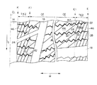
図1に示すように、空気入りタイヤ10のトレッド12には、タイヤ赤道面CL上に直線状の排水主溝14が形成され、タイヤ赤道面CLのタイヤ幅方向両側にも周溝16が形成されている。排水主溝14は、タイヤ10のトレッド12を、タイヤ周方向で2分して2つのトレッド半領域を形成している。空気入りタイヤ10のタイヤ幅方向両側からは、タイヤ赤道面CLに向かって湾曲し、周溝16に交差する横溝18が形成されている。横溝18は、周溝16と排水主溝14の中間部分において、回転方向に向かって屈曲しており、さらに、この屈曲部分の長手方向略中央からは、排水主溝14に連なる横溝24が形成されている。これらの排水主溝14、周溝16、及び横溝18、24は、本発明に係る主溝38であり、この主溝38によって、空気入りタイヤ10のトレッド12には複数個のブロック20(陸部)が画成されている。
As shown in FIG. 1, in the
本実施形態の空気入りタイヤ10は、冬用のスタッドレスタイヤとして用いられるものであって、トレッド12を形成しているトレッドゴムは、硬度(0°C、JIS−A)が50度であり、損失係数tanδ(ピーク位置)が−45°C、動的弾性率(−20°C、0.1%歪)が180kgf/cm2であるが、本発明はこれに限定されない。The
なお、冬用のスタッドレスタイヤとして用いる場合のトレッドゴムは、硬度(0°C、JIS−A)が40〜68度、損失係数tanδ(ピーク位置)が−30°C以下、動的弾性率(−20°C、0.1%歪)が300kgf/cm2以下であることが好ましい。The tread rubber used as a winter studless tire has a hardness (0 ° C., JIS-A) of 40 to 68 degrees, a loss coefficient tan δ (peak position) of −30 ° C. or less, and a dynamic elastic modulus ( −20 ° C., 0.1% strain) is preferably 300 kgf / cm 2 or less.
ここで、トレッドゴムの硬度が40度未満の場合は、柔らかすぎて耐摩耗性に劣り、68度より高い場合は硬すぎて氷雪路面との接触面積が減って制動性能・駆動性能等が劣るため好ましくない。また、損失係数tanδ(ピーク位置)が−30°より高いと、氷雪路面では剛すぎて接触面積が減って制動性能・駆動性能等に劣るため好ましくない。さらに、動的弾性率が300kgf/cm2よりも高いと、氷雪路面では剛すぎて接触面積が減って制動性能・駆動性能等に劣るため好ましくない。Here, when the hardness of the tread rubber is less than 40 degrees, it is too soft and inferior in wear resistance, and when it is higher than 68 degrees, it is too hard and the contact area with the snowy and snowy road surface decreases, resulting in inferior braking performance and driving performance. Therefore, it is not preferable. Further, if the loss coefficient tan δ (peak position) is higher than −30 °, it is not preferable because it is too stiff on the snowy and snowy road surface and the contact area is reduced, resulting in poor braking performance and driving performance. Furthermore, if the dynamic elastic modulus is higher than 300 kgf / cm 2 , it is not preferable because it is too stiff on the snowy and snowy road surface and the contact area is reduced, resulting in poor braking performance and driving performance.
一方、排水主溝14、周溝16、及び横溝18、24は、排水性及び寿命の点から溝深さ8mm以上、溝幅3mm以上とすることが好ましく、トレッド12の踏面のネガティブ比率は、同じく排水性の点、ブロック20の剛性の点から25〜65%とすることが好ましい。
On the other hand, the drainage
ここで、溝深さが8mm未満、また、溝幅が3mm未満では、溝による排水性が十分に発揮できないため好ましくない。また、ネガティブ比率が25%未満となると、排水性が低下するため好ましくなく、65%よりも高くなると陸部としてのブロック20が小さくなって剛性が低下するため、制動性能・駆動性能が低下する場合があり、耐摩耗性能も悪化するため好ましくない。
Here, if the groove depth is less than 8 mm and the groove width is less than 3 mm, the drainage by the groove cannot be sufficiently exhibited, which is not preferable. Further, if the negative ratio is less than 25%, the drainage performance is lowered, which is not preferable. If the negative ratio is higher than 65%, the
これらブロック20の踏面には、図3にも示すように、タイヤ幅方向(矢印W方向)に延びるジグザク状のサイプ22が設けられており、ブロック20のそれぞれが、主溝38−サイプ22間、又はサイプ22−サイプ22間の複数のサブブロック28に分割されている。
As shown in FIG. 3, zigzag
また、ブロック20の踏面には、路面との間に生じた水分を吸収して、水膜を除去あるいは減少させることの可能な浅溝26が設けられている。本実施形態の浅溝26は、タイヤ10の周方向に対して45°傾斜した直線をクロスさせた網目形状とされている。この浅溝26により、サブブロック28が微小陸部30に区画されている。浅溝26の深さは、空気入りタイヤ10のトレッド端をE、排水主溝14とブロック20との境界部分をKとすると、排水主溝14で2分された各々のトレッド半領域について、トレッド端Eからトレッド半領域の15%幅付近(この付近を浅溝変化部E1という)、及び、境界部分Kからブロック領域の15%幅付近(この部分を浅溝変化部K1という)において急激に変化されている。すなわち、トレッド端E−浅溝変化部E1の間に位置する、トレッド端領域TE1、TE2、及び、境界部分K−浅溝変化部K1の間に位置する、陸端部領域RE1、RE2の浅溝26の深さD1が、図2A、図4に示すように、その他の領域(以下「中央領域CE」という)に形成された浅溝26の深さD2よりも深くなっている。これにより、図2Bに示すように、ブロック20の表面を連続する仮想面Kで繋げた場合のタイヤ幅方向Wの断面での単位領域Hあたりの浅溝26の断面Aの面積の合計は、トレッド端領域TE1、TE2、及び、陸端部領域RE1、RE2の方が、中央領域CEよりも大きくなっている。
Further, the tread surface of the
なお、ここで、トレッド端Eは、タイヤ10の接地部分のタイヤ幅W方向の両接地端部であり、空気入りタイヤをJATMA YEAR BOOK(2004年度版、日本自動車タイヤ協会規格)に規定されている標準リムに装着し、JATMA YEAR BOOKでの適用サイズ・プライレーティングにおける最大負荷能力(内圧−負荷能力対応表の太字荷重)に対応する空気圧(最大空気圧)の100%の内圧を充填し、最大負荷能力を負荷したときのものである。
Here, the tread end E is both contact end portions in the tire width W direction of the contact portion of the
なお、使用地又は製造地において、TRA規格、ETRTO規格が適用される場合は各々の規格に従う。 When the TRA standard or ETRTO standard is applied at the place of use or manufacturing, the respective standards are followed.
そして、ここでのトレッド端領域TE1、TE2は、トレッド端Eから10mm以上の幅で、トレッド幅(一方のトレッド端Eから他方のトレッド端Eまでの距離)の1/6以内の幅の範囲であればよい。また、陸端部領域RE1、RE2についても同様に、排水主溝14との境界部分Kから10mm以上の幅で、トレッド幅の1/6以内の幅の範囲であればよい。
The tread end regions TE1 and TE2 here have a width of 10 mm or more from the tread end E and a width within 1/6 of the tread width (distance from one tread end E to the other tread end E). If it is. Similarly, the land end regions RE1 and RE2 may have a width of 10 mm or more from the boundary portion K with the drainage
図5に示すように、浅溝26の幅W1は、少なくともサイプ22の幅W2(図3参照)よりも狭く形成されているが、これらの幅は同程度、あるいはW1が、W2より広くてもよい。なお、浅溝26の幅W1は0.1mm〜1.0mmの範囲が好ましい。幅W1を1.0mm以下とすることで、微小陸部30の接地時における変形を抑制して、摩耗を少なくすることができる。
As shown in FIG. 5, the width W1 of the
図5に示すように、浅溝26は、断面形状が略矩形状を呈しており、その深さは0.1mm〜0.5mmの範囲が好ましい。深さD1及び幅W1を0.1mm以上とすることで、浅溝26内に取り込み可能な水分量を確保して、高い除水効果を得ることができる。また、その深さD1を0.5mm以下、幅W1を1.0mm以下とすることで、微小陸部30の接地時における変形を抑制して、摩耗を少なくすることができる。
As shown in FIG. 5, the
また、トレッド端領域TE1、TE2、及び、陸端部領域RE1、RE2の浅溝26の深さD1と、中央領域CEの浅溝26の深さD2との差は、0.1mm〜0.4mmの範囲が好ましい。
The difference between the depth D1 of the
また、微小陸部30の踏面面積としては、0.4mm2〜30mm2とすることが好ましい。踏面面積を0.4mm2以上とすることで、接地面積を確保して、空気入りタイヤ10の使用初期で高い性能を得ることが可能となる。また、30mm2以下に制限することで、浅溝26内に取り込み可能な水分量を確保して、高い除水効果を得ることができる。As the tread area of the
なお、浅溝26は、空気入りタイヤ10を加硫成型するモールドの内面に、切削加工、放電加工、エッチング加工等にて形成することができる。
The
また、浅溝26は成型後のタイヤや、走行に供されてある程度表面が摩耗したタイヤに形成することもでき、このようなタイヤにおいては、ナイフカットあるいは紙やすりなどによる表面バフ等により形成することができる。
The
次に、本実施形態の空気入りタイヤ10の作用を説明する。
Next, the effect | action of the
空気入りタイヤ10のトレッド12は、タイヤ径方向内側の内方ゴム層34(未発泡ゴム層)と、タイヤ径方向外側の外方ゴム層36(発泡ゴム層)とで構成されているが、使用初期では、踏面に、外方ゴム層36の気泡が露出していない。
The
使用初期状態の空気入りタイヤ10で氷雪路上を走行すると、トレッド12と氷または雪とが接触する際の圧力、摩擦等により水が発生する。摩擦力低下の原因となるこの水はブロック20の踏面に設けられた浅溝26内に取り込まれ、この溝部分を介して(あるいは、さらにサイプ22を介して)排水主溝14、周溝16、及び横溝18、24へと排出されるため、踏面と路面との間の水膜が除去される。
When the
このため、本実施形態の空気入りタイヤ10は、踏面に浅溝26が形成されていないタイヤに比較して、使用初期における氷雪路面での制動性能・駆動性能が向上すると共にウエット路面においても、浅溝26の排水効果によりウエット性能が向上する。
For this reason, the
特に本実施形態では、中央部CEトレッド端E付近のトレッド端領域TE1、TE2及び、排水主溝14と隣接する陸端部領域RE1、RE2に形成された浅溝26の深さが、中央領域CEに形成された浅溝26の深さよりも深くなっている。通常、この排水主溝14に隣接する陸部や、トレッド端E付近の接地圧は、他の部分と比較して高くなっている。したがって、雪道を走行した場合に、当該部分に多くの水分がにじみ出てくる。したがって、このように、トレッド端領域TE1、TE2、陸端部領域RE1、RE2に形成される浅溝26の深さの平均を深くすることにより、多くの水分を吸収することができ、効率よく排水効果を向上させることができる。
In particular, in the present embodiment, the depth of the
なお、本実施形態では、トレッド端領域TE1、TE2及び、陸端部領域RE1、RE2に形成する浅溝26の深さD1を一定とし、中央領域CEに形成する浅溝26の深さD2も一定としたが、必ずしも一定である必要はない。トレッド端領域TE1、TE2及び、陸端部領域RE1、RE2に形成する浅溝26の深さの平均が、中央領域CEに形成する浅溝26の深さの平均よりも深ければよい。
In the present embodiment, the depth D1 of the
また、本発明に係る浅溝としては、上記した網目形状の浅溝26に限定されず、図6に示すように、周方向に伸びる直線状の浅溝50であってもよい。この場合には、トレッド端領域TE1、TE2及び、陸端部領域RE1、RE2に形成する浅溝50の深さD3を深くし、中央領域CEに形成する浅溝50の深さD4をD3よりも浅くすればよい。
The shallow groove according to the present invention is not limited to the mesh-shaped
なお、浅溝は必ずしも本実施形態のような規則的なパターンで配置する必要もないが、規則的にパターン化すると、構造が簡単になり、しかも、トレッド面全体にわたって均一な性能を確保できるので、好ましい。 The shallow grooves do not necessarily have to be arranged in a regular pattern as in this embodiment. However, regular patterning simplifies the structure and ensures uniform performance over the entire tread surface. ,preferable.
また、本実施形態では、ブロック20にサイプ22が形成された空気入りタイヤ10を例に挙げたが、サイプ22が形成されていない空気入りタイヤに本発明を適用し、浅溝26をブロック20に形成することも可能である。この場合には、少なくとも排水主溝14、16、及び横溝18、24よりも浅溝を浅く且つ幅狭とすれば、空気入りタイヤの基本性能に浅溝26が与える影響を少なくでき、且つ浅溝26の本来的な効果である除水効果も維持できる。
In the present embodiment, the
また、主溝38によってブロック20が形成された空気入りタイヤ10に限らず、たとえばリブが形成された空気入りタイヤに対しても、このリブに浅溝を形成して本発明に係る空気入りタイヤとすることが可能である。
Further, not only the
また、ブロック20(又はリブ)として、発泡ゴム層で構成された外方ゴム層に代えて、氷上性能を向上させるために充填剤が充填されたゴムで構成されていてもよい。この構成であっても、空気入りタイヤの使用初期では踏面に充填剤が露出していないことが想定されるが、本実施形態のような浅溝を形成することで、空気入りタイヤの使用初期での性能を向上させることができる。 Moreover, it replaces with the outer rubber layer comprised with the foamed rubber layer as the block 20 (or rib), and may be comprised with the rubber with which the filler was filled in order to improve on-ice performance. Even in this configuration, it is assumed that the filler is not exposed on the tread at the initial use of the pneumatic tire, but by using the shallow groove as in this embodiment, the initial use of the pneumatic tire The performance at can be improved.
[第2実施形態]
次に、本発明の第2実施形態について説明する。本実施形態では、第1実施形態と同様の部分については同一の符号を付して詳細な説明は省略する。[Second Embodiment]
Next, a second embodiment of the present invention will be described. In the present embodiment, the same parts as those in the first embodiment are denoted by the same reference numerals, and detailed description thereof is omitted.
図7には、本発明の第2実施形態の空気入りタイヤ40が示されている。この空気入りタイヤ40は、第1実施形態で説明した空気入りタイヤ10と同様に回転方向があらかじめ決められている。図面においてこの回転方向を矢印Sで、これと直交するタイヤ幅方向を矢印Wでそれぞれ示す。なお、空気入りタイヤ40の周方向は、回転方向及びその反対方向となる。
FIG. 7 shows a pneumatic tire 40 according to a second embodiment of the present invention. The rotation direction of the pneumatic tire 40 is predetermined in the same manner as the
図8Aに示すように、この空気入りタイヤ40のトレッド42は、タイヤ径方向内側の内方ゴム層34と、タイヤ径方向外側の外方ゴム層36と、で構成されている。外方ゴム層36、及び、内方ゴム層34の構成は、第1実施形態と同様である。また、排水主溝14、周溝16、横溝18、横溝24、及び、ブロック20の構成についても、第1実施形態と同様である(図7参照)。
As shown in FIG. 8A, the
本実施形態の空気入りタイヤ40も、冬用のスタッドレスタイヤとして用いられるものであって、トレッド42を形成しているトレッドゴムの、硬度(0°C、JIS−A)、損失係数tanδ(ピーク位置)、動的弾性率(−20°C、0.1%歪)は、第1実施形態と同様であるが、本発明はこれに限定されない。
The pneumatic tire 40 of the present embodiment is also used as a winter studless tire, and the tread rubber forming the
また、排水主溝14、周溝16、及び横溝18、24の深さ、溝幅は、排水性及び寿命の点から溝深さ8mm以上、溝幅3mm以上とすることが好ましく、トレッド42の踏面のネガティブ比率は、同じく排水性の点、ブロック20の剛性の点から25〜65%とすることが好ましい。
Further, the depth and groove width of the drainage
ここで、溝深さが8mm未満、また、溝幅が3mm未満では、溝による排水性が十分に発揮できないため好ましくない。また、ネガティブ比率が25%未満となると、排水性が低下するため好ましくなく、65%よりも高くなると陸部としてのブロック20が小さくなって剛性が低下するため、制動性能・駆動性能が低下する場合があり、耐摩耗性能も悪化するため好ましくない。
Here, if the groove depth is less than 8 mm and the groove width is less than 3 mm, the drainage by the groove cannot be sufficiently exhibited, which is not preferable. Further, if the negative ratio is less than 25%, the drainage performance is lowered, which is not preferable. If the negative ratio is higher than 65%, the
これらブロック20の踏面には、図9にも示すように、タイヤ幅方向(矢印W方向)に延びるジグザク状のサイプ22が設けられており、ブロック20のそれぞれが、主溝38−サイプ22間、又はサイプ22−サイプ22間の複数のサブブロック28に分割されている。
As shown in FIG. 9, zigzag
また、ブロック20の踏面には、路面との間に生じた水分を吸収して、水膜を除去あるいは減少可能な浅溝46が設けられている。本実施形態の浅溝46は、排水主溝14からトレッド端Eに向かって回転方向後方側へ傾斜される方向に形成されている。この浅溝46により、サブブロック28が微小陸部44に区画されている。浅溝46のタイヤ周方向に対する角度は、空気入りタイヤ40のトレッド端をE、排水主溝14とブロック20との境界部分をKとすると、排水主溝14で2分された各々のブロック領域について、トレッド端Eからブロック領域の15%幅付近(この付近を浅溝変化部E1という)、及び、境界部分Kからブロック領域の15%幅付近(この部分を浅溝変化部K1という)において変化されている。本実施形態では、トレッド端E−浅溝変化部E1の間に位置する、トレッド端領域TE1、TE2、及び、境界部分K−浅溝変化部K1の間に位置する、陸端部領域RE1、RE2の浅溝46のタイヤ周方向に対する角度をθ1、その他の領域(以下「中央領域CE」という)に形成された浅溝46のタイヤ周方向に対する角度をθ2とすると、θ2がθ1よりも大きい角度とされている。これにより、図8Bに示すように、ブロック20の表面を連続する仮想面Kで繋げた場合のタイヤ幅方向Wの断面での単位領域Hあたりの浅溝46の断面Aの面積の合計は、トレッド端領域TE1、TE2、及び、陸端部領域RE1、RE2の方が、中央領域CEよりも大きくなっている。
Further, the tread surface of the
なお、ここでのトレッド端Eの位置、トレッド端領域TE1、TE2の範囲については、第1実施形態と同様である。 Here, the position of the tread end E and the ranges of the tread end regions TE1 and TE2 are the same as those in the first embodiment.
また、θ1とθ2との角度差は、2°〜60°であることが好ましい。 The angle difference between θ1 and θ2 is preferably 2 ° to 60 °.
図10に示すように、浅溝46の幅W1は、少なくともサイプ22の幅W2(図9参照)よりも狭く形成されているが、これらの幅は同程度、あるいはW1が、W2より広くてもよい。なお、浅溝46の幅W1は0.1mm〜1.0mmの範囲が好ましい。幅W1を1.0mm以下とすることで、微小陸部44の接地時における変形を抑制して、摩耗を少なくすることができる。
As shown in FIG. 10, the width W1 of the
図10に示すように、浅溝46は、断面形状が略矩形状を呈しており、その深さは0.1mm〜0.5mmの範囲が好ましい。深さD1及び幅W1を0.1mm以上とすることで、浅溝26内に取り込み可能な水分量を確保して、高い除水効果を得ることができる。また、その深さD1を0.5mm以下、幅W1を1.0mm以下とすることで、微小陸部44の接地時における変形を抑制して、摩耗を少なくすることができる。
As shown in FIG. 10, the
また、微小陸部44の踏面面積としては、0.4mm2〜30mm2とすることが好ましい。踏面面積を0.4mm2以上とすることで、接地面積を確保して、空気入りタイヤ10の使用初期で高い性能を得ることが可能となる。また、30mm2以下に制限することで、浅溝46内に取り込み可能な水分量を確保して、高い除水効果を得ることができる。As the tread area of the
なお、浅溝46は、空気入りタイヤ40を加硫成型するモールドの内面に、切削加工、放電加工、エッチング加工等にて形成することができる。
The
また、浅溝46は成型後のタイヤや、走行に供されてある程度表面が摩耗したタイヤに形成することもでき、このようなタイヤにおいては、ナイフカットあるいは紙やすりなどによる表面バフ等により形成することができる。
The
次に、本実施形態の空気入りタイヤ40の作用を説明する。 Next, the effect | action of the pneumatic tire 40 of this embodiment is demonstrated.
空気入りタイヤ40のトレッド12は、タイヤ径方向内側の内方ゴム層34(未発泡ゴム層)と、タイヤ径方向外側の外方ゴム層36(発泡ゴム層)とで構成されているが、使用初期では、踏面に、外方ゴム層36の気泡が露出していない。
The
使用初期状態の空気入りタイヤ40で氷雪路上を走行すると、トレッド42と氷または雪とが接触する際の圧力、摩擦等により水が発生する。摩擦力低下の原因となるこの水はブロック20の踏面に設けられた浅溝46内に取り込まれ、この溝部分を介して(あるいは、さらにサイプ22を介して)排水主溝14、周溝16、及び横溝18、24へと排出されるため、踏面と路面との間の水膜が除去される。
When the pneumatic tire 40 in the initial use state travels on an icy and snowy road, water is generated due to pressure, friction, and the like when the
このため、本実施形態の空気入りタイヤ40は、踏面に浅溝46が形成されていないタイヤに比較して、使用初期における氷雪路面での制動性能・駆動性能が向上すると共にウエット路面においても、浅溝46の排水効果によりウエット性能が向上する。
For this reason, the pneumatic tire 40 of the present embodiment has improved braking performance and driving performance on the icy and snowy road surface in the initial stage of use as compared with a tire in which the
特に本実施形態では、トレッド端E付近のトレッド端領域TE1、TE2、及び、排水主溝14と隣接する陸端部領域RE1、RE2に形成された浅溝46のタイヤ周方向に対する角度θ1が、中央領域CEに形成された浅溝46のタイヤ周方向に対する角度θ2よりも小さくなっている。したがって、浅溝46で吸収された水分を効率よくトレッド端E外側、及び、排水主溝14へ排出でき、排水性を向上させることができる。
Particularly in the present embodiment, the angle θ1 with respect to the tire circumferential direction of the tread end regions TE1 and TE2 near the tread end E and the
また、中央領域CEに形成された浅溝46のタイヤ周方向に対する角度θ2は、トレッド端領域TE1、TE2、及び、陸端部領域RE1、RE2に形成された浅溝46のタイヤ周方向に対する角度θ1よりも大きくなっている。したがって、エッジ効果を効率よく発揮することができる。
Further, the angle θ2 of the
なお、本実施形態では、浅溝46を直線状とし、角度θ1を一定、角度θ2を一定としたが、浅溝46は、必ずしも直線状である必要はない。図11に示すように、浅溝変化部E1付近、及び、浅溝変化部K1付近において、浅溝46の角部をなくし、曲線状とすることもできる。このような形状とすることにより、性能変化を緩やかにすることができる。
In the present embodiment, the
また、浅溝46のタイヤ周方向に対する角度は、トレッド端Eと境界部分Kとの中間部分で最も大きくし、排水主溝14、トレッド端Eに向かうにつれて徐々に小さくなるようにしてもよい。
Further, the angle of the
なお、浅溝は必ずしも本実施形態のような規則的なパターンで配置する必要もないが、規則的にパターン化すると、構造が簡単になり、しかも、トレッド面全体にわたって均一な性能を確保できるので、好ましい。 The shallow grooves do not necessarily have to be arranged in a regular pattern as in this embodiment. However, regular patterning simplifies the structure and ensures uniform performance over the entire tread surface. ,preferable.
また、本実施形態では、ブロック20にサイプ22が形成された空気入りタイヤ10を例に挙げたが、サイプ22が形成されていない空気入りタイヤに本発明を適用し、浅溝46をブロック20に形成することも可能である。この場合には、少なくとも排水主溝14、16、及び横溝18、24よりも浅溝を浅く且つ幅狭とすれば、空気入りタイヤの基本性能に浅溝46が与える影響を少なくでき、且つ浅溝46の本来的な効果である除水効果も維持できる。
In the present embodiment, the
また、主溝38によってブロック20が形成された空気入りタイヤ40に限らず、たとえばリブが形成された空気入りタイヤに対しても、このリブに浅溝を形成して本発明に係る空気入りタイヤとすることが可能である。
Further, not only the pneumatic tire 40 in which the
また、ブロック20(又はリブ)として、発泡ゴム層で構成された外方ゴム層に代えて、氷上性能を向上させるために充填剤が充填されたゴムで構成されていてもよい。この構成であっても、空気入りタイヤの使用初期では踏面に充填剤が露出していないことが想定されるが、本実施形態のような浅溝を形成することで、空気入りタイヤの使用初期での性能を向上させることができる。 Moreover, it replaces with the outer rubber layer comprised with the foamed rubber layer as the block 20 (or rib), and may be comprised with the rubber with which the filler was filled in order to improve on-ice performance. Even in this configuration, it is assumed that the filler is not exposed on the tread at the initial use of the pneumatic tire, but by using the shallow groove as in this embodiment, the initial use of the pneumatic tire The performance at can be improved.
なお、本実施形態では、トレッド端領域TE1、TE2、及び、陸端部領域RE1、RE2と中央領域CEとで、浅溝46の角度のみを変化させたが、第1実施形態で説明したように、浅溝の深さも変化させてもよい。
In the present embodiment, only the angle of the
[第3実施形態]
次に、本発明の第3実施形態について説明する。本実施形態では、第1、第2実施形態と同様の部分については同一の符号を付して詳細な説明は省略する。[Third Embodiment]
Next, a third embodiment of the present invention will be described. In the present embodiment, the same parts as those in the first and second embodiments are denoted by the same reference numerals, and detailed description thereof is omitted.
図12には、本発明の第3実施形態の空気入りタイヤ50が示されている。この空気入りタイヤ50は、第1実施形態で説明した空気入りタイヤ10と同様に回転方向があらかじめ決められている。図面においてこの回転方向を矢印Sで、これと直交するタイヤ幅方向を矢印Wでそれぞれ示す。なお、空気入りタイヤ10の周方向は、回転方向及びその反対方向となる。
FIG. 12 shows a
図13Aに示すように、この空気入りタイヤ50のトレッド52は、タイヤ径方向内側の内方ゴム層34と、タイヤ径方向外側の外方ゴム層36と、で構成されている。外方ゴム層36、及び、内方ゴム層34の構成は、第1実施形態と同様である。また、排水主溝14、周溝16、横溝18、横溝24、及び、ブロック20の構成についても、第1実施形態と同様である(図12参照)。
As shown in FIG. 13A, the
本実施形態の空気入りタイヤ50も、冬用のスタッドレスタイヤとして用いられるものであって、トレッド52を形成しているトレッドゴムの、硬度(0°C、JIS−A)、損失係数tanδ(ピーク位置)、動的弾性率(−20°C、0.1%歪)は、第1実施形態と同様であるが、本発明はこれに限定されない。
The
また、排水主溝14、周溝16、及び横溝18、24の深さ、溝幅は、排水性及び寿命の点から溝深さ8mm以上、溝幅3mm以上とすることが好ましく、トレッド52の踏面のネガティブ比率は、同じく排水性の点、ブロック20の剛性の点から25〜65%とすることが好ましい。
In addition, the depth and groove width of the drainage
ここで、溝深さが8mm未満、また、溝幅が3mm未満では、溝による排水性が十分に発揮できないため好ましくない。また、ネガティブ比率が25%未満となると、排水性が低下するため好ましくなく、65%よりも高くなると陸部としてのブロック20が小さくなって剛性が低下するため、制動性能・駆動性能が低下する場合があり、耐摩耗性能も悪化するため好ましくない。
Here, if the groove depth is less than 8 mm and the groove width is less than 3 mm, the drainage by the groove cannot be sufficiently exhibited, which is not preferable. Further, if the negative ratio is less than 25%, the drainage performance is lowered, which is not preferable. If the negative ratio is higher than 65%, the
これらブロック20の踏面には、図14にも示すように、タイヤ幅方向(矢印W方向)に延びるジグザク状のサイプ22が設けられており、ブロック20のそれぞれが、主溝38−サイプ22間、又はサイプ22−サイプ22間の複数のサブブロック28に分割されている。
As shown in FIG. 14, zigzag
また、ブロック20の踏面には、路面との間に生じた水分を吸収して、水膜を除去あるいは減少可能な浅溝56が設けられている。本実施形態の浅溝56は、空気入りタイヤ50の周方向に沿った直線状とされている。この浅溝56により、サブブロック28が微小陸部54に区画されている。浅溝56の形成間隔は、空気入りタイヤ50のトレッド端をE、排水主溝14とブロック20との境界部分をKとすると、排水主溝14で2分された各々のトレッド半領域について、トレッド端Eと境界部分Kとのタイヤ幅方向Wの中間部分で最も広く、この中間部分からトレッド端E、排水主溝14に近づくにつれて徐々に狭くなっている。これにより、トレッド端E付近のトレッド端領域TE1、TE2及び、排水主溝14と隣接する陸端部領域RE1、RE2に形成された浅溝56の密度は、その他の領域(以下「中央領域CE」という)に形成された浅溝56の密度よりも大きくなっている。これにより、図13Bに示すように、ブロック20の表面を連続する仮想面Kで繋げた場合のタイヤ幅方向Wの断面での単位領域Hあたりの浅溝56の断面Aの面積の合計は、トレッド端領域TE1、TE2、及び、陸端部領域RE1、RE2の方が、中央領域CEよりも大きくなっている。
The tread surface of the
なお、ここでのトレッド端Eの位置、トレッド端領域TE1、TE2の範囲については、第1実施形態と同様である。 Here, the position of the tread end E and the ranges of the tread end regions TE1 and TE2 are the same as those in the first embodiment.
図15に示すように、浅溝56の幅W1は、少なくともサイプ22の幅W2(図14参照)よりも狭く形成されているが、これらの幅は同程度、あるいはW1が、W2より広くてもよい。なお、浅溝56の幅W1は0.1mm〜1.0mmの範囲が好ましい。幅W1を1.0mm以下とすることで、微小陸部30の接地時における変形を抑制して、摩耗を少なくすることができる。
As shown in FIG. 15, the width W1 of the
図15に示すように、浅溝56は、断面形状が略矩形状を呈しており、その深さD1は0.1mm〜0.5mmの範囲が好ましい。深さD1及び幅W1を0.1mm以上とすることで、浅溝56内に取り込み可能な水分量を確保して、高い除水効果を得ることができる。また、その深さD1を0.5mm以下、幅W1を1.0mm以下とすることで、微小陸部54の接地時における変形を抑制して、摩耗を少なくすることができる。
As shown in FIG. 15, the
また、微小陸部54の踏面面積としては、0.4mm2〜30mm2とすることが好ましい。踏面面積を0.4mm2以上とすることで、接地面積を確保して、空気入りタイヤ50の使用初期で高い性能を得ることが可能となる。また、30mm2以下に制限することで、浅溝56内に取り込み可能な水分量を確保して、高い除水効果を得ることができる。As the tread area of the
なお、浅溝56は、空気入りタイヤ50を加硫成型するモールドの内面に、切削加工、放電加工、エッチング加工等にて形成することができる。
The
また、浅溝56は成型後のタイヤや、走行に供されてある程度表面が摩耗したタイヤに形成することもでき、このようなタイヤにおいては、ナイフカットあるいは紙やすりなどによる表面バフ等により形成することができる。
The
次に、本実施形態の空気入りタイヤ50の作用を説明する。
Next, the operation of the
空気入りタイヤ50のトレッド52は、タイヤ径方向内側の内方ゴム層34(未発泡ゴム層)と、タイヤ径方向外側の外方ゴム層36(発泡ゴム層)とで構成されているが、使用初期では、踏面に、外方ゴム層36の気泡が露出していない。
The
使用初期状態の空気入りタイヤ50で氷雪路上を走行すると、トレッド52と氷または雪とが接触する際の圧力、摩擦等により水が発生する。摩擦力低下の原因となるこの水はブロック20の踏面に設けられた浅溝56内に取り込まれ、この溝部分を介して(あるいは、さらにサイプ22を介して)排水主溝14、周溝16、及び横溝18、24へと排出されるため、踏面と路面との間の水膜が除去される。
When the
このため、本実施形態の空気入りタイヤ50は、踏面に浅溝56が形成されていないタイヤに比較して、使用初期における氷雪路面での制動性能・駆動性能が向上すると共にウエット路面においても、浅溝56の排水効果によりウエット性能が向上する。
For this reason, the
特に本実施形態では、トレッド端E付近のトレッド端領域TE1、TE2及び、排水主溝14と隣接する陸端部領域RE1、RE2に形成された浅溝56の密度が、中央領域CEに形成された浅溝56の密度よりも大きくなっている。通常、この排水主溝14に隣接する陸部や、トレッド端E付近の接地圧は、他の部分と比較して高くなっている。したがって、雪道を走行した場合に、当該部分に多くの水分がにじみ出てくる。したがって、このように、トレッド端領域TE1、TE2、陸端部領域RE1、RE2に形成される浅溝26の密度を大きくすることにより、多くの水分を吸収することができ、効率よく排水効果を向上させることができる。
In particular, in the present embodiment, the density of the
なお、本発明に係る浅溝としては、上記した直線状の浅溝56に限定されず、図16に示すように、タイヤ周方向Sに伸びるジグザグ形状の浅溝58であっても、図17に示すように、タイヤ周方向に伸びる波形形状の浅溝59であってもよい。
The shallow groove according to the present invention is not limited to the linear
また、本発明に係る浅溝としては、図18に示すように、半円形状の半円形浅溝60としてもよい。半円形浅溝60は、半径がトレッド幅の1/4以上とされ、タイヤ回転方向に凸状となる略半円形状とされている。半円形浅溝60が、タイヤ周方向Sに所定間隔で並べられて、半円形溝群が構成される。
The shallow groove according to the present invention may be a semicircular semicircular
このように、半円形浅溝60を複数並べることにより、容易にトレッド端領域TE、及び陸端部領域REに形成される浅溝の密度を中央領域CEに形成される浅溝の密度よりも大きくすることができる。また、タイヤ回転方向に略半円形状とすることにより、効率よく排水を行なうことができる。
In this way, by arranging a plurality of semicircular
なお、ここでの略半円形は、中心角度が120°〜180°であることが好ましい。 In addition, as for the substantially semicircle here, it is preferable that center angles are 120 degrees-180 degrees.
また、半径は、トレッド幅の1/4以上1/2以下であればよい。さらに、この半円形浅溝60の曲率は、排水主溝間の間隔、タイヤ幅方向の接地幅との関係から、5mm〜150mmであることが好ましい。
Further, the radius may be from 1/4 to 1/2 of the tread width. Furthermore, the curvature of the semicircular
なお、浅溝は必ずしも本実施形態のような規則的なパターンで配置する必要もないが、規則的にパターン化すると、構造が簡単になり、しかも、トレッド面全体にわたって均一な性能を確保できるので、好ましい。 The shallow grooves do not necessarily have to be arranged in a regular pattern as in this embodiment. However, regular patterning simplifies the structure and ensures uniform performance over the entire tread surface. ,preferable.
また、本実施形態では、ブロック20にサイプ22が形成された空気入りタイヤ50を例に挙げたが、サイプ22が形成されていない空気入りタイヤに本発明を適用し、浅溝56をブロック20に形成することも可能である。この場合には、少なくとも排水主溝14、16、及び横溝18、24よりも浅溝を浅く且つ幅狭とすれば、空気入りタイヤの基本性能に浅溝56が与える影響を少なくでき、且つ浅溝56の本来的な効果である除水効果も維持できる。
In the present embodiment, the
また、主溝38によってブロック20が形成された空気入りタイヤ50に限らず、たとえばリブが形成された空気入りタイヤに対しても、このリブに浅溝を形成して本発明に係る空気入りタイヤとすることが可能である。
Further, not only the
また、ブロック20(又はリブ)として、発泡ゴム層で構成された外方ゴム層に代えて、氷上性能を向上させるために充填剤が充填されたゴムで構成されていてもよい。この構成であっても、空気入りタイヤの使用初期では踏面に充填剤が露出していないことが想定されるが、本実施形態のような浅溝を形成することで、空気入りタイヤの使用初期での性能を向上させることができる。 Moreover, it replaces with the outer rubber layer comprised with the foamed rubber layer as the block 20 (or rib), and may be comprised with the rubber with which the filler was filled in order to improve on-ice performance. Even in this configuration, it is assumed that the filler is not exposed on the tread at the initial use of the pneumatic tire, but by using the shallow groove as in this embodiment, the initial use of the pneumatic tire The performance at can be improved.
なお、本実施形態では、トレッド端領域TE1、TE2、及び、陸端部領域RE1、RE2と中央領域CEとで、浅溝46の密度のみを変化させたが、第1実施形態で説明したように、浅溝の深さも変化させてもよいし、第2実施形態で説明したように、浅溝の角度も変化させてもよく、さらには、浅溝の深さと角度の両方を変化させてもよい。
In the present embodiment, only the density of the
次に、本発明を実施例により、さらに詳細に説明する。 Next, the present invention will be described in more detail with reference to examples.
実施例1では、図1〜図5に示す第1実施形態の空気入りタイヤ10を乗用車に装着し、使用初期における氷上性能を評価した。浅溝26の深さD1は0.65mm、深さD2は0.5mmとした。
In Example 1, the
また、比較例1として、浅溝26の深さをすべての領域において一定とし、その他をタイヤ10と同一条件としたタイヤを使用して、同じく使用初期における氷上性能を評価した。
Further, as Comparative Example 1, the performance on ice in the initial stage of use was similarly evaluated using a tire in which the depth of the
実施例1、比較例1の各々の空気入りタイヤの基本的な構成と、氷上性能の評価を表1に示す。 Table 1 shows the basic configuration of each of the pneumatic tires of Example 1 and Comparative Example 1 and the evaluation of the performance on ice.

これら実施例1及び比較例1では、共通の条件として、
・タイヤサイズ:195/65R16
・使用リム :6J−15
・使用内圧 :210kPa(フロント、リヤ同じ)
とした。In these Example 1 and Comparative Example 1, as common conditions,
・ Tire size: 195 / 65R16
・ Rim used: 6J-15
・ Internal pressure: 210 kPa (same for front and rear)
It was.
<試験方法及び評価方法>
・氷上加速
氷上で5km/hから15km/hへと加速するのに要する時間を計測し、比較例1を100として実施例1を相対的に指数評価した。数値が大きくなるほど加速性能に優れていることを示す。<Test method and evaluation method>
-Acceleration on ice The time required to accelerate from 5 km / h to 15 km / h on ice was measured, and Comparative Example 1 was taken as 100, and Example 1 was relatively indexed. The larger the value, the better the acceleration performance.
・制動距離
氷上で20km/hの定速走行中にブレーキロックにより0km/hへと減速するのに要した制動距離を測定し、比較例1を100として実施例1を相対的に指数評価した。数値が小さくなるほど制動性能に優れていることを示す。-Braking distance During braking at a constant speed of 20 km / h on ice, the braking distance required to decelerate to 0 km / h by brake lock was measured, and comparative example 1 was taken as 100 and Example 1 was relatively indexed. . The smaller the value, the better the braking performance.
表1から、実施例1では比較例1よりも、氷上での加速性能、制動性能の両方において優れていることが分かる。実施例1ではトレッド端領域TE1、TE2、及び、陸端部領域RE1、RE2において、比較例1よりも浅溝26の深さを深くしたためであると考えられる。
From Table 1, it can be seen that Example 1 is superior to Comparative Example 1 in both acceleration performance and braking performance on ice. In Example 1, it is considered that the depth of the
実施例2は、図7〜図10に示す第2実施形態の空気入りタイヤ40を乗用車に装着し、使用初期における氷上性能を評価した。浅溝26の角度θ1を15°、角度θ2を45°とした。
In Example 2, the pneumatic tire 40 of the second embodiment shown in FIGS. 7 to 10 was mounted on a passenger car, and the performance on ice in the initial use was evaluated. The angle θ1 of the
また、比較例2として、浅溝46のタイヤ周方向とに対する傾斜角度は、すべて45°とし(図19参照)、その他を空気入りタイヤ40と同一条件としたタイヤを使用して、同じく使用初期における氷上性能を評価した。
Further, as Comparative Example 2, the inclination angles of the
実施例2、比較例2の各々の空気入りタイヤの基本的な構成と、氷上性能の評価を表2に示す。 Table 2 shows the basic configuration of each pneumatic tire of Example 2 and Comparative Example 2 and the evaluation of the performance on ice.
これら実施例2及び比較例2では、共通の条件として、
・タイヤサイズ:195/65R16
・使用リム :6J−15
・使用内圧 :210kPa(フロント、リヤ同じ)
とした。In these Example 2 and Comparative Example 2, as common conditions,
・ Tire size: 195 / 65R16
・ Rim used: 6J-15
・ Internal pressure: 210 kPa (same for front and rear)
It was.
<試験方法及び評価方法>
・氷上加速
氷上で5km/hから15km/hへと加速するのに要する時間を計測し、比較例2を100として実施例2を相対的に指数評価した。数値が大きくなるほど加速性能に優れていることを示す。<Test method and evaluation method>
-Acceleration on ice The time required to accelerate from 5 km / h to 15 km / h on ice was measured, and Comparative Example 2 was taken as 100, and Example 2 was relatively indexed. The larger the value, the better the acceleration performance.
・制動距離
氷上で20km/hの定速走行中にブレーキロックにより0km/hへと減速するのに要した制動距離を測定し、比較例2を100として実施例2を相対的に指数評価した。数値が小さくなるほど制動性能に優れていることを示す。-Braking distance During braking at a constant speed of 20 km / h on ice, the braking distance required to decelerate to 0 km / h by brake lock was measured, and Comparative Example 2 was taken as 100 and Example 2 was relatively indexed. . The smaller the value, the better the braking performance.
表2から、実施例2では比較例2よりも、氷上での加速性能、制動性能の両方において優れていることが分かる。実施例2ではトレッド端領域TE1、TE2、及び、陸端部領域RE1、RE2において、比較例2よりも浅溝26のタイヤ周方向に対する傾斜角度を小さくしたためであると考えられる。
Table 2 shows that Example 2 is superior to Comparative Example 2 in both acceleration performance and braking performance on ice. In Example 2, it is considered that the inclination angle of the
実施例3では、図12〜図5に示す第3実施形態の空気入りタイヤ10を乗用車に装着し、使用初期における氷上性能を評価した。空気入りタイヤ50の1つの微小陸部54の面積は、トレッド端領域TE1、TE2、及び、陸端部領域RE1、RE2で1〜10mm2、中央領域CEで略10mm2、とされている。In Example 3, the
また、比較例3として、図20に示す空気入りタイヤを使用して、同じく使用初期における氷上性能を評価した。この空気入りタイヤは、タイヤ周方向Sに沿った直線状の浅溝58が等間隔に形成されており、微小陸部54の面積は、10mm2とされている。実施例と比較例とでは、浅溝間隔が異なる点以外の基本的構成は同一であり、図20においても同一部分は図12と同符号を付している。Further, as Comparative Example 3, the performance on ice in the initial use was similarly evaluated using the pneumatic tire shown in FIG. In this pneumatic tire, straight
実施例3、比較例3の空気入りタイヤの基本的な構成と、氷上性能の評価を表3に示す。 Table 3 shows the basic configuration of the pneumatic tires of Example 3 and Comparative Example 3 and the evaluation of performance on ice.
これら実施例3及び比較例3では、共通の条件として、
・タイヤサイズ:195/65R16
・使用リム :6J−15
・使用内圧 :210kPa(フロント、リヤ同じ)
とした。In these Example 3 and Comparative Example 3, as common conditions,
・ Tire size: 195 / 65R16
・ Rim used: 6J-15
・ Internal pressure: 210 kPa (same for front and rear)
It was.
<試験方法及び評価方法>
・氷上加速
氷上で5km/hから15km/hへと加速するのに要する時間を計測し、比較例3を100として実施例3を相対的に指数評価した。数値が大きくなるほど加速性能に優れていることを示す。<Test method and evaluation method>
-Acceleration on ice The time required to accelerate from 5 km / h to 15 km / h on ice was measured, and Comparative Example 3 was taken as 100, and Example 3 was relatively indexed. The larger the value, the better the acceleration performance.
・制動距離
氷上で20km/hの定速走行中にブレーキロックにより0km/hへと減速するのに要した制動距離を測定し、比較例3を100として実施例3を相対的に指数評価した。数値が小さくなるほど制動性能に優れていることを示す。-Braking distance During braking at a constant speed of 20 km / h on ice, the braking distance required to decelerate to 0 km / h by brake lock was measured, and Comparative Example 3 was taken as 100 and Example 3 was relatively indexed. . The smaller the value, the better the braking performance.
表3から、実施例3では比較例3よりも、氷上での加速性能、制動性能の両方において優れていることが分かる。実施例3ではトレッド端領域TE1、TE2、及び、陸端部領域RE1、RE2において、比較例3よりも浅溝26の形成密度を大きくしたためであると考えられる。
From Table 3, it can be seen that Example 3 is superior to Comparative Example 3 in both acceleration performance and braking performance on ice. In Example 3, it is considered that the formation density of the
10、40、50 空気入りタイヤ
14 排水主溝
16 周溝
18、24 横溝
20 ブロック
22 サイプ
26、46、56、58、59 浅溝
28 サブブロック
30、44 54 微小陸部
38 主溝
10, 40, 50
Claims (14)
前記複数の主溝の少なくとも1本は主たる排水溝としての排水主溝であり、
前記陸部に、前記サイプよりも浅い浅溝が複数形成され、
前記トレッド面のタイヤ幅方向の端部側に配置されるトレッド端部領域、及び、前記陸部の前記排水主溝に隣接する陸端部領域の少なくとも一方の領域において、タイヤ幅方向の断面での単位領域あたりの前記浅溝の断面積の合計が、他の領域における前記単位領域あたりの前記浅溝の断面積の合計よりも大きく、
前記トレッド端部領域、及び、前記陸端部領域の少なくとも一方の領域における前記浅溝の深さの平均が、他の領域の前記浅溝の深さの平均よりも深いことを特徴とする空気入りタイヤ。In a pneumatic tire having a plurality of land portions partitioned by a plurality of main grooves on a tread surface, and the land portions are divided by at least one sipe extending in the tire width direction to form sub-blocks,
At least one of the plurality of main grooves is a drain main groove as a main drain groove,
A plurality of shallow grooves shallower than the sipe are formed in the land portion,
In at least one region of the tread end region disposed on the end side in the tire width direction of the tread surface and the land end region adjacent to the drain main groove of the land portion, in a cross section in the tire width direction The sum of the cross-sectional areas of the shallow grooves per unit region of the other is larger than the sum of the cross-sectional areas of the shallow grooves per unit region in other regions,
The average depth of the shallow grooves in at least one of the tread edge region and the land edge region is deeper than the average depth of the shallow grooves in other regions. Tires.
前記浅溝の深さの平均が、前記トレッド端部領域と、前記中央周溝の両側に配置された前記陸端領域とで同一であること、を特徴とする請求項1に記載の空気入りタイヤ。The drainage main groove constitutes a central circumferential groove formed along the tire circumferential direction at the center of the tread surface in the tire width direction,
The average of the depth of the said shallow groove is the same in the said tread edge part area | region and the said land edge area | region arrange | positioned at the both sides of the said center circumferential groove, The pneumatic of Claim 1 characterized by the above-mentioned. tire.
前記複数の主溝の少なくとも1本は主たる排水溝としての排水主溝であり、
前記陸部に、前記サイプよりも浅い浅溝が複数形成され、
前記トレッド面のタイヤ幅方向の端部側に配置されるトレッド端部領域、及び、前記陸部の前記排水主溝に隣接する陸端部領域の少なくとも一方の領域において、タイヤ幅方向の断面での単位領域あたりの前記浅溝の断面積の合計が、他の領域における前記単位領域あたりの前記浅溝の断面積の合計よりも大きく、
前記トレッド端部領域、及び、前記陸端部領域の少なくとも一方の領域における前記浅溝の形成密度が、他の領域の前記浅溝の形成密度よりも大きく、
前記浅溝の形成密度は、前記トレッド面の前記中央周溝と両トレッド端との各々の中間部分が最小とされ、トレッド端方向及び中央周溝方向に向かって漸増すること、を特徴とする空気入りタイヤ。 In a pneumatic tire having a plurality of land portions partitioned by a plurality of main grooves on a tread surface, and the land portions are divided by at least one sipe extending in the tire width direction to form sub-blocks,
At least one of the plurality of main grooves is a drain main groove as a main drain groove,
A plurality of shallow grooves shallower than the sipe are formed in the land portion,
In at least one region of the tread end region disposed on the end side in the tire width direction of the tread surface and the land end region adjacent to the drain main groove of the land portion, in a cross section in the tire width direction The sum of the cross-sectional areas of the shallow grooves per unit region of the other is larger than the sum of the cross-sectional areas of the shallow grooves per unit region in other regions,
The formation density of the shallow grooves in at least one of the tread edge region and the land edge region is larger than the formation density of the shallow grooves in the other region,
The formation density of the shallow grooves is such that the intermediate portion of each of the central circumferential groove and both tread ends of the tread surface is minimized, and gradually increases toward the tread end direction and the central circumferential groove direction. Pneumatic tire.
前記複数の主溝の少なくとも1本は主たる排水溝としての排水主溝であり、
前記陸部に、前記サイプよりも浅い浅溝が複数形成され、
前記トレッド面のタイヤ幅方向の端部側に配置されるトレッド端部領域、及び、前記陸部の前記排水主溝に隣接する陸端部領域の少なくとも一方の領域において、タイヤ幅方向の断面での単位領域あたりの前記浅溝の断面積の合計が、他の領域における前記単位領域あたりの前記浅溝の断面積の合計よりも大きく、
前記トレッド端部領域、及び、前記陸端部領域の少なくとも一方の領域における前記浅溝の形成密度が、他の領域の前記浅溝の形成密度よりも大きく、
前記排水主溝が前記トレッド面のタイヤ幅方向の中央部にタイヤ周方向に沿って形成された中央周溝であり、
前記浅溝の形成密度が、前記トレッド端部領域と、前記中央周溝の両側に配置された前記陸端領域とで同一であること、を特徴とする空気入りタイヤ。 In a pneumatic tire having a plurality of land portions partitioned by a plurality of main grooves on a tread surface, and the land portions are divided by at least one sipe extending in the tire width direction to form sub-blocks,
At least one of the plurality of main grooves is a drain main groove as a main drain groove,
A plurality of shallow grooves shallower than the sipe are formed in the land portion,
In at least one region of the tread end region disposed on the end side in the tire width direction of the tread surface and the land end region adjacent to the drain main groove of the land portion, in a cross section in the tire width direction The sum of the cross-sectional areas of the shallow grooves per unit region of the other is larger than the sum of the cross-sectional areas of the shallow grooves per unit region in other regions,
The formation density of the shallow grooves in at least one of the tread edge region and the land edge region is larger than the formation density of the shallow grooves in the other region,
The drainage main groove is a central circumferential groove formed along the tire circumferential direction at the center of the tread surface in the tire width direction,
The formation density of the said shallow groove is the same in the said tread edge part area | region and the said land edge area | region arrange | positioned at the both sides of the said center circumferential groove, The pneumatic tire characterized by the above-mentioned .
前記複数の主溝の少なくとも1本は主たる排水溝としての排水主溝であり、
前記陸部に、前記サイプよりも浅い浅溝が複数形成され、
前記トレッド面のタイヤ幅方向の端部側に配置されるトレッド端部領域、及び、前記陸部の前記排水主溝に隣接する陸端部領域の少なくとも一方の領域において、タイヤ幅方向の断面での単位領域あたりの前記浅溝の断面積の合計が、他の領域における前記単位領域あたりの前記浅溝の断面積の合計よりも大きく、
前記トレッド端部領域、及び、前記陸端部領域の少なくとも一方の領域における前記浅溝の形成密度が、他の領域の前記浅溝の形成密度よりも大きく、
前記浅溝は、タイヤ周方向に沿って直線状に形成され、前記トレッド端部領域、及び前記陸端部領域の少なくとも一方の前記浅溝の形成間隔が、他の領域の前記浅溝の形成間隔よりも小さいこと、を特徴とする空気入りタイヤ。 In a pneumatic tire having a plurality of land portions partitioned by a plurality of main grooves on a tread surface, and the land portions are divided by at least one sipe extending in the tire width direction to form sub-blocks,
At least one of the plurality of main grooves is a drain main groove as a main drain groove,
A plurality of shallow grooves shallower than the sipe are formed in the land portion,
In at least one region of the tread end region disposed on the end side in the tire width direction of the tread surface and the land end region adjacent to the drain main groove of the land portion, in a cross section in the tire width direction The sum of the cross-sectional areas of the shallow grooves per unit region of the other is larger than the sum of the cross-sectional areas of the shallow grooves per unit region in other regions,
The formation density of the shallow grooves in at least one of the tread edge region and the land edge region is larger than the formation density of the shallow grooves in the other region,
The shallow groove is formed linearly along the tire circumferential direction, and the formation interval of the shallow groove in at least one of the tread end region and the land end region is the formation of the shallow groove in another region. A pneumatic tire characterized by being smaller than the interval .
前記複数の主溝の少なくとも1本は主たる排水溝としての排水主溝であり、
前記陸部に、前記サイプよりも浅い浅溝が複数形成され、
前記トレッド面のタイヤ幅方向の端部側に配置されるトレッド端部領域、及び、前記陸部の前記排水主溝に隣接する陸端部領域の少なくとも一方の領域において、タイヤ幅方向の断面での単位領域あたりの前記浅溝の断面積の合計が、他の領域における前記単位領域あたりの前記浅溝の断面積の合計よりも大きく、
前記トレッド端部領域、及び、前記陸端部領域の少なくとも一方の領域における前記浅溝の形成密度が、他の領域の前記浅溝の形成密度よりも大きく、
前記浅溝は、トレッド幅の1/4以上の半径で前記中央周溝を挟んだ両側の各トレッド半領域の各々に形成されタイヤの回転方向に凸状となる略半円形状とされた半円形浅溝を、タイヤ周方向に複数並べて構成される半円形溝群を含んでいること、を特徴とする空気入りタイヤ。 In a pneumatic tire having a plurality of land portions partitioned by a plurality of main grooves on a tread surface, and the land portions are divided by at least one sipe extending in the tire width direction to form sub-blocks,
At least one of the plurality of main grooves is a drain main groove as a main drain groove,
A plurality of shallow grooves shallower than the sipe are formed in the land portion,
In at least one region of the tread end region disposed on the end side in the tire width direction of the tread surface and the land end region adjacent to the drain main groove of the land portion, in a cross section in the tire width direction The sum of the cross-sectional areas of the shallow grooves per unit region of the other is larger than the sum of the cross-sectional areas of the shallow grooves per unit region in other regions,
The formation density of the shallow grooves in at least one of the tread edge region and the land edge region is larger than the formation density of the shallow grooves in the other region,
The shallow groove is formed in each of the tread half regions on both sides sandwiching the central circumferential groove with a radius of 1/4 or more of the tread width, and is a semi-circular shape that is convex in the tire rotation direction. A pneumatic tire characterized by including a semi-circular groove group configured by arranging a plurality of circular shallow grooves in the tire circumferential direction .
Applications Claiming Priority (7)
| Application Number | Priority Date | Filing Date | Title |
|---|---|---|---|
| JP2004345866 | 2004-11-30 | ||
| JP2004345851 | 2004-11-30 | ||
| JP2004345851 | 2004-11-30 | ||
| JP2004345866 | 2004-11-30 | ||
| JP2004345848 | 2004-11-30 | ||
| JP2004345848 | 2004-11-30 | ||
| PCT/JP2005/021983 WO2006059640A1 (en) | 2004-11-30 | 2005-11-30 | Pneumatic tire |
Publications (2)
| Publication Number | Publication Date |
|---|---|
| JPWO2006059640A1 JPWO2006059640A1 (en) | 2008-06-05 |
| JP4519141B2 true JP4519141B2 (en) | 2010-08-04 |
Family
ID=36565074
Family Applications (1)
| Application Number | Title | Priority Date | Filing Date |
|---|---|---|---|
| JP2006547976A Expired - Fee Related JP4519141B2 (en) | 2004-11-30 | 2005-11-30 | Pneumatic tire |
Country Status (4)
| Country | Link |
|---|---|
| US (1) | US8020595B2 (en) |
| EP (1) | EP1829712B1 (en) |
| JP (1) | JP4519141B2 (en) |
| WO (1) | WO2006059640A1 (en) |
Cited By (1)
| Publication number | Priority date | Publication date | Assignee | Title |
|---|---|---|---|---|
| DE102018221492A1 (en) | 2017-12-13 | 2019-06-13 | Toyo Tire & Rubber Co., Ltd. | Pneumatic tire |
Families Citing this family (22)
| Publication number | Priority date | Publication date | Assignee | Title |
|---|---|---|---|---|
| DE102005042569A1 (en) * | 2005-09-08 | 2007-03-22 | Continental Aktiengesellschaft | Vehicle tires |
| JP4145337B2 (en) * | 2007-01-17 | 2008-09-03 | 横浜ゴム株式会社 | Pneumatic tire |
| JP4378414B1 (en) * | 2008-05-28 | 2009-12-09 | 横浜ゴム株式会社 | Pneumatic tire |
| USD608724S1 (en) | 2009-03-16 | 2010-01-26 | Trek Bicycle Corporation | Bicycle tire tread |
| JP5099203B2 (en) * | 2010-10-04 | 2012-12-19 | 横浜ゴム株式会社 | Pneumatic tire |
| JP5893375B2 (en) * | 2011-12-08 | 2016-03-23 | 東洋ゴム工業株式会社 | Pneumatic tire |
| DE102012112016A1 (en) * | 2012-12-10 | 2014-06-12 | Continental Reifen Deutschland Gmbh | Vehicle tires |
| JP5898640B2 (en) * | 2013-04-23 | 2016-04-06 | 住友ゴム工業株式会社 | Pneumatic tire |
| CA159352S (en) * | 2014-05-15 | 2015-09-24 | Hankook Tire Co Ltd | Tire |
| CA159328S (en) * | 2014-05-15 | 2015-09-21 | Hankook Tire Co Ltd | Tire |
| DE102014212902A1 (en) | 2014-07-03 | 2016-01-07 | Continental Reifen Deutschland Gmbh | Vehicle tires |
| USD754058S1 (en) * | 2014-12-18 | 2016-04-19 | The Goodyear Tire & Rubber Company | Tire |
| DE102015224290A1 (en) * | 2015-12-04 | 2017-06-08 | Continental Reifen Deutschland Gmbh | Vehicle tires |
| RU2704766C1 (en) * | 2016-02-26 | 2019-10-30 | Дзе Йокогама Раббер Ко., Лтд. | Pneumatic tire |
| JP7095370B2 (en) * | 2018-04-06 | 2022-07-05 | 住友ゴム工業株式会社 | tire |
| JP7035740B2 (en) | 2018-04-06 | 2022-03-15 | 住友ゴム工業株式会社 | tire |
| CN111376654B (en) * | 2018-12-27 | 2022-04-01 | 通伊欧轮胎株式会社 | Pneumatic tire |
| DE102019208322A1 (en) * | 2019-06-07 | 2020-12-10 | Continental Reifen Deutschland Gmbh | Pneumatic vehicle tires |
| CN115443222B (en) * | 2020-05-28 | 2024-02-23 | 横滨橡胶株式会社 | Pneumatic tire |
| JP7540203B2 (en) * | 2020-06-04 | 2024-08-27 | 住友ゴム工業株式会社 | Pneumatic tires |
| JP7099503B2 (en) * | 2020-09-10 | 2022-07-12 | 横浜ゴム株式会社 | tire |
| JP7028491B1 (en) * | 2021-06-22 | 2022-03-02 | みゆき 山田 | Tread part of vehicle tires |
Citations (4)
| Publication number | Priority date | Publication date | Assignee | Title |
|---|---|---|---|---|
| JPH05330319A (en) * | 1992-06-04 | 1993-12-14 | Bridgestone Corp | Block of tire and pneumatic tire |
| JPH07186633A (en) * | 1993-11-22 | 1995-07-25 | Bridgestone Corp | Pneumatic tire |
| JP2006051873A (en) * | 2004-08-11 | 2006-02-23 | Toyo Tire & Rubber Co Ltd | Pneumatic tire |
| JP2006076556A (en) * | 2004-08-09 | 2006-03-23 | Sumitomo Rubber Ind Ltd | Pneumatic tire |
Family Cites Families (10)
| Publication number | Priority date | Publication date | Assignee | Title |
|---|---|---|---|---|
| US2821231A (en) * | 1954-12-31 | 1958-01-28 | Gen Tire & Rubber Co | Transversely-slitted tire tread |
| JP2824680B2 (en) * | 1989-12-18 | 1998-11-11 | 横浜ゴム株式会社 | Pneumatic tires for icy and snowy roads |
| US5385189A (en) * | 1991-11-01 | 1995-01-31 | Bridgestone Corporation | Pneumatic tire with paired sides in the tread |
| JP3017677B2 (en) | 1996-06-10 | 2000-03-13 | 住友ゴム工業株式会社 | Winter passenger car tires |
| JP4272301B2 (en) * | 1998-06-18 | 2009-06-03 | 住友ゴム工業株式会社 | Tread pattern forming method |
| JP2002240042A (en) * | 2001-02-15 | 2002-08-28 | Bridgestone Corp | Mold for vulcanizing and molding tire |
| JP3702958B2 (en) | 2002-07-05 | 2005-10-05 | 横浜ゴム株式会社 | Pneumatic tire for icy and snowy roads |
| JP4285599B2 (en) | 2002-07-05 | 2009-06-24 | 横浜ゴム株式会社 | Pneumatic tires for snowy and snowy roads |
| US7438100B2 (en) * | 2002-07-05 | 2008-10-21 | They Yokohama Rubber Co., Ltd. | Pneumatic tire for ice-bound or snow-covered road |
| JP4378414B1 (en) * | 2008-05-28 | 2009-12-09 | 横浜ゴム株式会社 | Pneumatic tire |
-
2005
- 2005-11-30 WO PCT/JP2005/021983 patent/WO2006059640A1/en active Application Filing
- 2005-11-30 US US11/791,768 patent/US8020595B2/en not_active Expired - Fee Related
- 2005-11-30 EP EP05811565A patent/EP1829712B1/en not_active Not-in-force
- 2005-11-30 JP JP2006547976A patent/JP4519141B2/en not_active Expired - Fee Related
Patent Citations (4)
| Publication number | Priority date | Publication date | Assignee | Title |
|---|---|---|---|---|
| JPH05330319A (en) * | 1992-06-04 | 1993-12-14 | Bridgestone Corp | Block of tire and pneumatic tire |
| JPH07186633A (en) * | 1993-11-22 | 1995-07-25 | Bridgestone Corp | Pneumatic tire |
| JP2006076556A (en) * | 2004-08-09 | 2006-03-23 | Sumitomo Rubber Ind Ltd | Pneumatic tire |
| JP2006051873A (en) * | 2004-08-11 | 2006-02-23 | Toyo Tire & Rubber Co Ltd | Pneumatic tire |
Cited By (1)
| Publication number | Priority date | Publication date | Assignee | Title |
|---|---|---|---|---|
| DE102018221492A1 (en) | 2017-12-13 | 2019-06-13 | Toyo Tire & Rubber Co., Ltd. | Pneumatic tire |
Also Published As
| Publication number | Publication date |
|---|---|
| EP1829712A4 (en) | 2009-03-25 |
| US8020595B2 (en) | 2011-09-20 |
| WO2006059640A1 (en) | 2006-06-08 |
| US20080135150A1 (en) | 2008-06-12 |
| JPWO2006059640A1 (en) | 2008-06-05 |
| EP1829712A1 (en) | 2007-09-05 |
| EP1829712B1 (en) | 2012-06-13 |
Similar Documents
| Publication | Publication Date | Title |
|---|---|---|
| JP4519141B2 (en) | Pneumatic tire | |
| JP4589680B2 (en) | Pneumatic tire | |
| JP6812359B2 (en) | tire | |
| CN101468583A (en) | Pneumatic tire | |
| JP5015421B2 (en) | Pneumatic tire | |
| JP2008007047A (en) | Pneumatic tire | |
| JP4285609B2 (en) | Pneumatic tire | |
| JP4571482B2 (en) | Pneumatic tire | |
| JP4621012B2 (en) | Pneumatic tire | |
| JP5170416B2 (en) | Pneumatic tires for snowy and snowy roads | |
| JP4628151B2 (en) | Pneumatic tire | |
| JP4557693B2 (en) | Pneumatic tire | |
| JP2006103522A (en) | Pneumatic tire for icy road | |
| JP2006151229A (en) | Pneumatic tire | |
| JP2008049971A (en) | Pneumatic tire | |
| JP4568099B2 (en) | Pneumatic tire | |
| JP2006151230A (en) | Pneumatic tire | |
| JP2006151231A (en) | Pneumatic tire | |
| JP2006035933A (en) | Pneumatic tire | |
| JP5104046B2 (en) | Pneumatic tire | |
| JP4526364B2 (en) | Pneumatic tire | |
| JP4621011B2 (en) | Pneumatic tire | |
| JP2006062468A (en) | Pneumatic tire | |
| JP2006151223A (en) | Pneumatic tire | |
| JP2006151237A (en) | Pneumatic tire |
Legal Events
| Date | Code | Title | Description |
|---|---|---|---|
| A621 | Written request for application examination |
Free format text: JAPANESE INTERMEDIATE CODE: A621 Effective date: 20080529 |
|
| A131 | Notification of reasons for refusal |
Free format text: JAPANESE INTERMEDIATE CODE: A131 Effective date: 20100223 |
|
| A521 | Request for written amendment filed |
Free format text: JAPANESE INTERMEDIATE CODE: A523 Effective date: 20100413 |
|
| TRDD | Decision of grant or rejection written | ||
| A01 | Written decision to grant a patent or to grant a registration (utility model) |
Free format text: JAPANESE INTERMEDIATE CODE: A01 Effective date: 20100511 |
|
| A01 | Written decision to grant a patent or to grant a registration (utility model) |
Free format text: JAPANESE INTERMEDIATE CODE: A01 |
|
| A61 | First payment of annual fees (during grant procedure) |
Free format text: JAPANESE INTERMEDIATE CODE: A61 Effective date: 20100518 |
|
| FPAY | Renewal fee payment (event date is renewal date of database) |
Free format text: PAYMENT UNTIL: 20130528 Year of fee payment: 3 |
|
| R150 | Certificate of patent or registration of utility model |
Ref document number: 4519141 Country of ref document: JP Free format text: JAPANESE INTERMEDIATE CODE: R150 Free format text: JAPANESE INTERMEDIATE CODE: R150 |
|
| R250 | Receipt of annual fees |
Free format text: JAPANESE INTERMEDIATE CODE: R250 |
|
| R250 | Receipt of annual fees |
Free format text: JAPANESE INTERMEDIATE CODE: R250 |
|
| R250 | Receipt of annual fees |
Free format text: JAPANESE INTERMEDIATE CODE: R250 |
|
| R250 | Receipt of annual fees |
Free format text: JAPANESE INTERMEDIATE CODE: R250 |
|
| R250 | Receipt of annual fees |
Free format text: JAPANESE INTERMEDIATE CODE: R250 |
|
| R250 | Receipt of annual fees |
Free format text: JAPANESE INTERMEDIATE CODE: R250 |
|
| R250 | Receipt of annual fees |
Free format text: JAPANESE INTERMEDIATE CODE: R250 |
|
| R250 | Receipt of annual fees |
Free format text: JAPANESE INTERMEDIATE CODE: R250 |
|
| LAPS | Cancellation because of no payment of annual fees |