JP4506474B2 - Combustion switching control system for compression ignition internal combustion engine - Google Patents
Combustion switching control system for compression ignition internal combustion engine Download PDFInfo
- Publication number
- JP4506474B2 JP4506474B2 JP2005008102A JP2005008102A JP4506474B2 JP 4506474 B2 JP4506474 B2 JP 4506474B2 JP 2005008102 A JP2005008102 A JP 2005008102A JP 2005008102 A JP2005008102 A JP 2005008102A JP 4506474 B2 JP4506474 B2 JP 4506474B2
- Authority
- JP
- Japan
- Prior art keywords
- combustion
- fuel injection
- injection
- premixed
- internal combustion
- Prior art date
- Legal status (The legal status is an assumption and is not a legal conclusion. Google has not performed a legal analysis and makes no representation as to the accuracy of the status listed.)
- Expired - Fee Related
Links
Images


Classifications
-
- Y—GENERAL TAGGING OF NEW TECHNOLOGICAL DEVELOPMENTS; GENERAL TAGGING OF CROSS-SECTIONAL TECHNOLOGIES SPANNING OVER SEVERAL SECTIONS OF THE IPC; TECHNICAL SUBJECTS COVERED BY FORMER USPC CROSS-REFERENCE ART COLLECTIONS [XRACs] AND DIGESTS
- Y02—TECHNOLOGIES OR APPLICATIONS FOR MITIGATION OR ADAPTATION AGAINST CLIMATE CHANGE
- Y02T—CLIMATE CHANGE MITIGATION TECHNOLOGIES RELATED TO TRANSPORTATION
- Y02T10/00—Road transport of goods or passengers
- Y02T10/10—Internal combustion engine [ICE] based vehicles
- Y02T10/12—Improving ICE efficiencies
Landscapes
- Output Control And Ontrol Of Special Type Engine (AREA)
- Electrical Control Of Air Or Fuel Supplied To Internal-Combustion Engine (AREA)
- Combined Controls Of Internal Combustion Engines (AREA)
Description
本発明は、いわゆる予混合燃焼と拡散燃焼である通常燃焼とを行う圧縮着火内燃機関において、燃焼切替を制御する圧縮着火内燃機関の燃焼切替制御システムに関する。 The present invention relates to a combustion switching control system for a compression ignition internal combustion engine that controls combustion switching in a compression ignition internal combustion engine that performs so-called premixed combustion and normal combustion that is diffusion combustion.
圧縮着火内燃機関において、NOxの抑制とスモークの抑制を目的として予混合燃焼を行う場合、該圧縮着火内燃機関の運転状態が高負荷運転状態となって機関負荷および機関回転速度が上昇するに従い、過早着火が生じる可能性が高くなる。そこで、該圧縮着火内燃機関の運転状態に基づいて、低・中負荷時は予混合燃焼を行い、高負荷時は通常燃焼を行う技術が公開されている(例えば、特許文献1を参照。)。この技術においては、予混合燃焼から通常燃焼への切替は、一サイクル中に予混合燃焼と通常燃焼の双方を行う多段噴射を経由して行われる。これにより、燃焼切替の円滑化を図ろうとするものである。 In a compression ignition internal combustion engine, when premixed combustion is performed for the purpose of suppressing NOx and smoke, as the operation state of the compression ignition internal combustion engine becomes a high load operation state and the engine load and the engine speed increase, The possibility of premature ignition increases. Therefore, a technique for performing premixed combustion at low / medium loads and normal combustion at high loads based on the operating state of the compression ignition internal combustion engine is disclosed (for example, see Patent Document 1). . In this technique, switching from premixed combustion to normal combustion is performed via multistage injection in which both premixed combustion and normal combustion are performed during one cycle. As a result, it is intended to facilitate combustion switching.
また、圧縮着火内燃機関で予混合燃焼を行う場合と通常燃焼を行う場合とにおいて、再循環排気(いわゆるEGRガスであって、既燃焼ガスを含む。)の気筒内への供給量が大きく異なる。即ち、予混合燃焼においては、過早着火を抑制するために通常燃焼時と比べて多量のEGRガスが必要とされる。そこで、圧縮着火内燃機関において予混合燃焼と通常燃焼とを切り替える場合において、EGRガス量が燃焼の切替に適した量となったときに予混合燃焼と通常燃焼との切替を行う技術が公開されている(例えば、特許文献2を参照。)。
運転状態に応じて予混合燃焼と通常燃焼とを切り替えて行う圧縮着火内燃機関において、燃焼の切替時には燃焼が不安定となったりエミッションが悪化したりするのを回避して燃焼切替を円滑に行うために、予混合燃焼時および通常燃焼時に行われている燃料噴射制御とは異なる燃料噴射制御が行われる。 In a compression ignition internal combustion engine that switches between premixed combustion and normal combustion according to operating conditions, combustion switching is smoothly performed while avoiding unstable combustion and worsening of emissions when switching combustion. Therefore, fuel injection control different from the fuel injection control performed at the time of premixed combustion and normal combustion is performed.
この燃焼切替は、圧縮着火内燃機関に対して加速指令が出され、内燃機関の負荷領域が予混合燃焼を行う負荷領域から通常燃焼を行う負荷領域に移行したときに行われる。しかし、その際、加速の程度は常に一定ではなく、そのため気筒内に残留するEGRガス量は加速の程度に応じて変化する。そのため、燃焼切替時に常に同じ燃焼切替のための燃料噴射を行うと、燃焼状態が悪化する虞がある。 This combustion switching is performed when an acceleration command is issued to the compression ignition internal combustion engine and the load region of the internal combustion engine shifts from a load region where premixed combustion is performed to a load region where normal combustion is performed. However, at that time, the degree of acceleration is not always constant, so the amount of EGR gas remaining in the cylinder changes according to the degree of acceleration. Therefore, if fuel injection for the same combustion switching is always performed at the time of combustion switching, the combustion state may be deteriorated.
本発明では、上記した問題に鑑み、圧縮着火内燃機関の運転状態に応じて予混合燃焼と通常燃焼とを切り替えて行う圧縮着火内燃機関において、燃焼切替時の燃焼状態の悪化を抑制することを目的とする。 In the present invention, in view of the above problems, in a compression ignition internal combustion engine that switches between premixed combustion and normal combustion in accordance with the operation state of the compression ignition internal combustion engine, it is possible to suppress deterioration of the combustion state at the time of combustion switching. Objective.
本発明は、上記した課題を解決するために、予混合燃焼から通常燃焼への切替を行う燃焼切替制御システムにおいて、燃焼切替時に行う燃焼遷移状態での燃料噴射(以下、「遷
移時燃料噴射」という。)が行われる遷移時間に着目した。この遷移時間を常時一定とすると、予混合燃焼から通常燃焼へと切り替わる際の圧縮着火内燃機関の運転状態の変動の様子、即ち加速の程度は一定ではないため、場合によっては気筒内に残留するEGRガス量が過剰に多すぎたりまたは少なすぎたりする。そこで、この遷移時間を可変とした。
In order to solve the above-described problems, the present invention provides a fuel switching control system that switches from premixed combustion to normal combustion in a combustion transition state that is performed during combustion switching (hereinafter referred to as “fuel injection during transition”). Focused on the transition time during which. If this transition time is always constant, the state of fluctuation of the operation state of the compression ignition internal combustion engine when switching from premixed combustion to normal combustion, that is, the degree of acceleration is not constant. The amount of EGR gas is too much or too little. Therefore, the transition time is variable.
詳細には、本発明は、圧縮着火内燃機関の燃料を気筒内に噴射する燃料噴射弁と、前記圧縮着火内燃機関の運転状態が、該圧縮着火内燃機関で行われる燃焼に応じた燃焼領域のいずれに属しているかを判定する燃焼領域判定手段と、を備え、前記燃焼領域判定手段によって判定される燃焼領域に応じて、前記燃料噴射弁の燃料噴射条件を制御することで、圧縮行程上死点近傍の時期より早い時期の燃料噴射によって予混合気を形成することで行われる予混合燃焼と圧縮行程上死点近傍の時期の燃料噴射によって行われる通常燃焼とを切り替えて行う圧縮着火内燃機関の燃焼切替制御システムであって、予混合燃焼から通常燃焼への燃焼切替状態である燃焼遷移状態では、予混合燃焼時および通常燃焼時とは異なる燃料噴射である遷移時燃料噴射が行われ、且つ該遷移時燃料噴射が行われる遷移時間は、前記圧縮着火内燃機関の所定運転状態に基づいて決定される。 Specifically, the present invention relates to a fuel injection valve that injects fuel of a compression ignition internal combustion engine into a cylinder, and an operation state of the compression ignition internal combustion engine in a combustion region corresponding to combustion performed in the compression ignition internal combustion engine. A combustion region determining means for determining which one belongs, and controlling a fuel injection condition of the fuel injection valve in accordance with the combustion region determined by the combustion region determining means, thereby causing the compression stroke top dead A compression ignition internal combustion engine that switches between premixed combustion performed by forming a premixed gas by fuel injection earlier than the timing near the point and normal combustion performed by fuel injection at a timing near the compression stroke top dead center In the combustion switching control system of the present invention, in the fuel transition state that is the combustion switching state from the premixed combustion to the normal combustion, the fuel injection at the transition that is a fuel injection different from that at the time of the premixed combustion and the normal combustion Is performed, and the and the transition time the transition time of the fuel injection is performed is determined based on a predetermined operating condition of the compression ignition internal combustion engine.
上述の圧縮着火内燃機関においては、圧縮着火内燃機関の機関回転速度や機関負荷等によって決定される運転状態がどの燃焼領域に属するか、即ち燃焼領域判定手段によって判定される燃焼領域が、予混合燃焼が行われる予混合燃焼領域と通常燃焼が行われる通常燃焼領域との何れであるかによって、該内燃機関で行われる燃焼が決定される。この予混合燃焼領域および通常燃焼領域は、予混合燃焼時の過早着火の生じやすさ等に基づいて実験等で決定される。 In the compression ignition internal combustion engine described above, the combustion region to which the operating state determined by the engine rotational speed, the engine load, etc. of the compression ignition internal combustion engine belongs, that is, the combustion region determined by the combustion region determination means is premixed. The combustion performed in the internal combustion engine is determined depending on whether the premixed combustion region where combustion is performed or the normal combustion region where normal combustion is performed. The premixed combustion region and the normal combustion region are determined by experiments or the like based on the likelihood of premature ignition during premixed combustion.
ここで、圧縮着火内燃機関において予混合燃焼を行う場合は、燃料噴射を圧縮行程上死点近傍の時期、即ち通常燃焼時の燃料噴射時期より早い時期に行うことで、吸気と燃料がより混合された予混合気を形成する。これによって、NOxやスモークの抑制を図る。尚、本発明における予混合燃焼においては、予混合燃料を一回の燃料噴射で噴射する場合に限られず、気筒の内壁面に燃料が付着するのを回避する等の理由で複数回の燃料噴射によって予混合燃料を噴射する場合も含まれる。また、通常燃焼時は、圧縮行程上死点近傍の時期に燃料を噴射していわゆる拡散燃焼が行われる。 Here, when premixed combustion is performed in a compression ignition internal combustion engine, the fuel injection is performed at a timing near the top dead center of the compression stroke, that is, at a timing earlier than the fuel injection timing at the time of normal combustion, thereby further mixing the intake air and the fuel. A premixed gas mixture is formed. As a result, NOx and smoke are suppressed. Note that the premixed combustion in the present invention is not limited to the case where the premixed fuel is injected by one fuel injection, but a plurality of times of fuel injection for reasons such as avoiding the fuel from adhering to the inner wall surface of the cylinder. This includes the case where the premixed fuel is injected. During normal combustion, so-called diffusion combustion is performed by injecting fuel at a time near the top dead center of the compression stroke.
圧縮着火内燃機関で予混合燃焼が行われているときに圧縮着火内燃機関の運転状態が変動し燃焼領域判定手段によって判定された燃焼領域が予混合燃焼領域から通常燃焼領域へ移行することで、予混合燃焼から通常燃焼への切替が行われる。この燃焼の切替時には予混合燃焼時の燃料噴射と通常燃焼時の燃料噴射とは異なる態様の遷移時燃料噴射が行われる。 When the pre-combustion combustion is performed in the compression ignition internal combustion engine, the operating state of the compression ignition internal combustion engine fluctuates and the combustion region determined by the combustion region determination means shifts from the premix combustion region to the normal combustion region, Switching from premixed combustion to normal combustion is performed. When the combustion is switched, the fuel injection at the time of transition is different from the fuel injection at the time of premixed combustion and the fuel injection at the time of normal combustion.
予混合燃焼時の燃料噴射状態から通常燃焼時の燃料噴射状態に急激に切り替えると、気筒内のEGRガス量が通常燃焼に適した量に変化し終えていないため、エミッションが悪化する虞があり、該エミッション悪化を回避するためにこの遷移時燃料噴射が行われる。即ち、遷移時燃料噴射は、気筒内で予混合燃焼が行われた状態から通常燃焼が行われる状態に至るまでの燃焼遷移状態にのみ適用される燃料噴射の態様である。 If the fuel injection state at the time of premixed combustion is suddenly switched to the fuel injection state at the time of normal combustion, the amount of EGR gas in the cylinder has not yet changed to an amount suitable for normal combustion, so there is a risk that emissions will deteriorate. In order to avoid the deterioration of the emission, the fuel injection at the transition is performed. That is, the fuel injection during transition is a mode of fuel injection that is applied only to the combustion transition state from the state where premixed combustion is performed in the cylinder to the state where normal combustion is performed.
ここで、圧縮着火内燃機関の運転状態は常に一定ではなく、然るに予混合燃焼から通常燃焼へ燃焼状態が切り替わる際の圧縮着火内燃機関の運転状態の変動、即ち加速の程度も常に一定ではない。例えば、機関負荷が徐々に増加していく段階で燃焼状態が予混合燃焼から通常燃焼へ切り替わる場合もあれば、機関負荷が急激に増加することで予混合燃焼から通常燃焼へ切り替わる場合もある。その結果、予混合燃焼から通常燃焼への切替を行う場合、その際の圧縮着火内燃機関の運転状態の変動によっては、気筒内の残留EGRガス量が変動するため、遷移時燃料噴射が行われる遷移時間を一定とすると遷移時燃料噴射と
残留EGRガス量との均衡が保てず、燃焼状態が悪化する虞がある。
Here, the operation state of the compression ignition internal combustion engine is not always constant. However, the fluctuation of the operation state of the compression ignition internal combustion engine when the combustion state is switched from premixed combustion to normal combustion, that is, the degree of acceleration is not always constant. For example, the combustion state may be switched from premixed combustion to normal combustion when the engine load is gradually increased, or the engine load may be suddenly increased to switch from premixed combustion to normal combustion. As a result, when switching from premixed combustion to normal combustion, the amount of residual EGR gas in the cylinder varies depending on the variation in the operating state of the compression ignition internal combustion engine at that time, so that fuel injection at transition is performed. If the transition time is constant, the balance between the fuel injection during transition and the residual EGR gas amount cannot be maintained, and the combustion state may be deteriorated.
そこで上記の圧縮着火内燃機関の燃焼切替制御システムにおいては、圧縮着火内燃機関の所定運転状態に基づいて可変とする。即ち、圧縮着火内燃機関の運転状態の変動を顕著に反映する所定運転状態に基づいて遷移時燃料噴射が行われる遷移時間を調整することで、遷移時燃料噴射と残留EGRガス量との均衡を保ち、予混合燃焼から通常燃焼への切替を、より円滑に、且つ燃焼状態を悪化させることなく実行することが可能となる。ここで、該所定運転状態として、例えば、圧縮着火内燃機関におけるアクセル開度および機関回転速度が挙げられる。 Therefore, in the combustion switching control system for the compression ignition internal combustion engine, the compression ignition internal combustion engine is variable based on a predetermined operation state. That is, by adjusting the transition time in which the fuel injection at the transition is performed based on the predetermined operation state that significantly reflects the fluctuation of the operation state of the compression ignition internal combustion engine, the balance between the fuel injection at the transition and the residual EGR gas amount is balanced. Thus, the switching from the premixed combustion to the normal combustion can be performed more smoothly and without deteriorating the combustion state. Here, examples of the predetermined operating state include an accelerator opening and an engine speed in a compression ignition internal combustion engine.
上記の圧縮着火内燃機関の燃焼切替制御システムにおいては、前記アクセル開度が開くに従いおよび/または前記機関回転速度が高くなるに従い、前記遷移時間は短くなるようにしてもよい。アクセル開度が開けば開くほど、または機関回転速度が高くなればなるほど、圧縮着火内燃機関の運転状態の変動は急であることを意味し、そのような場合は予混合燃焼が行われる時間が短く、気筒内に残留するEGRガス量は比較的少ない。そこで、そのような場合は、遷移時間をより短くして通常燃焼への切替をより早く行う。このようにすることで、気筒内に残留するEGRガスに適した切替時の燃焼を行うことが可能となり、以て燃焼状態の悪化を抑制し得る。 In the combustion switching control system for a compression ignition internal combustion engine, the transition time may be shortened as the accelerator opening is opened and / or as the engine speed is increased. This means that the more the accelerator opening is opened, or the higher the engine speed, the more sudden the change in the operating state of the compression ignition internal combustion engine is. In such a case, the time for premixed combustion is performed. The amount of EGR gas that is short and remains in the cylinder is relatively small. Therefore, in such a case, the transition time is shortened and switching to normal combustion is performed earlier. By doing in this way, it becomes possible to perform combustion at the time of switching suitable for the EGR gas remaining in the cylinder, and thus deterioration of the combustion state can be suppressed.
また、上述までの圧縮着火内燃機関の燃焼切替制御システムにおいて、前記遷移時燃料噴射には、予混合燃焼時の予混合燃料噴射を、該予混合燃料噴射の燃料噴射時期近くのプレ噴射と該プレ噴射後のメイン噴射とに変更するとともに該プレ噴射の噴射量を該メイン噴射の噴射量以上とする第一燃料噴射モードと、該メイン噴射の噴射時期を通常燃焼における圧縮行程上死点近傍の燃料噴射時期に向けて移行させ、且つ該プレ噴射の噴射量を減量するとともに該メイン噴射の噴射量を増量し該メイン噴射の噴射量を該プレ噴射の噴射量より多くする第二燃料噴射モードと、が採用され、燃料噴射時期を除く燃料噴射に関する制御パラメータは、予混合燃焼時および前記第一燃料噴射モード採用時には予混合燃焼に対応した予混合燃焼制御マップより算出され、通常燃焼時には通常燃焼に対応した通常燃焼制御マップより算出されるとともに、前記第二燃料噴射モード採用時には該予混合燃焼制御マップと該通常燃焼制御マップのそれぞれによって算出される値に時間なましが適用された中間値とされてもよい。 In the combustion switching control system for a compression ignition internal combustion engine as described above, the pre-injection fuel near the fuel injection timing of the premixed fuel injection and the preinjection fuel near the fuel injection timing of the premixed fuel injection are included in the fuel injection at the transition. The first fuel injection mode in which the pre-injection is changed to the main injection and the injection amount of the pre-injection is greater than or equal to the injection amount of the main injection, and the injection timing of the main injection is near the top dead center of the compression stroke in normal combustion The second fuel injection that shifts toward the fuel injection timing of the first fuel injection, decreases the injection amount of the pre-injection, increases the injection amount of the main injection, and makes the injection amount of the main injection larger than the injection amount of the pre-injection The control parameters relating to fuel injection excluding the fuel injection timing are premixed combustion control maps corresponding to premixed combustion during premixed combustion and when the first fuel injection mode is employed. And is calculated from the normal combustion control map corresponding to normal combustion at the time of normal combustion, and to the value calculated by each of the premixed combustion control map and the normal combustion control map when the second fuel injection mode is adopted. It may be an intermediate value to which time annealing is applied.
遷移時燃料噴射の特徴点は、上記の第一燃料噴射モードと第二燃料噴射モードの二つの形態を採用している点である。先ず、第一燃料噴射モードでは、燃焼切替前の予混合燃焼時の燃料噴射をプレ噴射とメイン噴射の二段噴射とする。ここで、この二段噴射は、その二段噴射開始直後は、プレ噴射の燃料噴射時期を予混合燃焼時の燃料噴射時期の近くとすることで、圧縮着火内燃機関における燃焼状態を予混合燃焼から急激に変更することを回避する。そして、プレ噴射後にメイン噴射を行うことで、燃焼切替後の通常燃焼における燃料噴射の基礎を形成する。このとき、第一燃料噴射モードでは、予混合燃焼時の燃料噴射形態が反映されるため、プレ噴射の噴射量をメイン噴射の噴射量以上とする。 The characteristic point of the fuel injection at the time of transition is that two forms of the first fuel injection mode and the second fuel injection mode are employed. First, in the first fuel injection mode, fuel injection at the time of premixed combustion before combustion switching is set to two-stage injection of pre-injection and main injection. Here, in this two-stage injection, immediately after the start of the two-stage injection, the pre-injection fuel injection timing is set close to the fuel injection timing at the time of premix combustion, so that the combustion state in the compression ignition internal combustion engine is premix combustion. Avoid sudden changes from. Then, by performing main injection after pre-injection, the basis of fuel injection in normal combustion after combustion switching is formed. At this time, in the first fuel injection mode, the fuel injection mode at the time of premixed combustion is reflected, so the injection amount of the pre-injection is set to be equal to or greater than the injection amount of the main injection.
次に、第二燃料噴射モードでは、上記のメイン噴射の燃料噴射時期を通常燃焼における燃料噴射時期に向けて移行させることで、予混合燃焼から通常燃焼への切替を進めていく。そして、メイン噴射の燃料噴射時期を通常燃焼における燃料噴射時期に向けて移行させるとき、プレ噴射の燃料噴射量を減量するとともにメイン噴射の燃料噴射量を増量する。即ち、第一燃料噴射モードでは、燃焼状態が予混合燃焼から急激に変化するのを回避するためにプレ噴射の燃料噴射量を多くするとともにメイン噴射の燃料噴射量を少なくし、第二燃料噴射モードでは、最終的には切替後の通常燃焼に近づけるべくプレ噴射の燃料噴射量を少なくしメイン噴射の燃料噴射量を多くするものである。 Next, in the second fuel injection mode, the switching from the premixed combustion to the normal combustion is advanced by shifting the fuel injection timing of the main injection toward the fuel injection timing in the normal combustion. When the fuel injection timing of the main injection is shifted toward the fuel injection timing in the normal combustion, the fuel injection amount of the pre-injection is decreased and the fuel injection amount of the main injection is increased. That is, in the first fuel injection mode, in order to avoid a sudden change in the combustion state from the premixed combustion, the fuel injection amount of the pre-injection is increased, the fuel injection amount of the main injection is decreased, and the second fuel injection mode is decreased. In the mode, the fuel injection amount of the pre-injection is decreased and the fuel injection amount of the main injection is increased in order to finally approach the normal combustion after switching.
尚、この燃料噴射時期や燃料噴射量を変化させる制御は、燃焼状態の急変を回避するために徐々に行うのが好ましいと思われるが、燃焼状態が不安定となったりエミッションが悪化したりしない範囲で段階的に行ってもよく、また、急変させてもよい。 It should be noted that the control for changing the fuel injection timing and the fuel injection amount is preferably performed gradually in order to avoid a sudden change in the combustion state, but the combustion state does not become unstable or the emission does not deteriorate. It may be performed step by step in the range, or may be changed suddenly.
以上より、遷移時燃料噴射が行われることで、圧縮着火内燃機関の運転状態に応じて予混合燃焼から通常燃焼への切り替えをより円滑に行うことが可能となる。 As described above, by performing fuel injection at the time of transition, it is possible to more smoothly switch from premixed combustion to normal combustion in accordance with the operating state of the compression ignition internal combustion engine.
ここで、燃料噴射時期は上述したようにそれぞれの燃料噴射形態によって決定されるが、それ以外の燃料噴射に関する制御パラメータの決定においては、それぞれの燃料噴射形態が反映している燃焼状態が考慮される。即ち、遷移時燃料噴射実行時に第一燃料噴射モードが採用されている場合は、上述したように該形態が予混合燃焼時の燃料噴射を反映しているため、予混合燃焼実行時と同様に、燃料噴射時期以外の燃料噴射に関する制御パラメータは予混合燃焼制御マップより算出される。この予混合燃焼制御マップは、予混合燃焼時の燃焼状態が良好なものとなるために決定された制御マップである。 Here, as described above, the fuel injection timing is determined according to each fuel injection mode. However, in determining other control parameters relating to fuel injection, the combustion state reflected in each fuel injection mode is considered. The That is, when the first fuel injection mode is adopted at the time of transitional fuel injection execution, as described above, the form reflects the fuel injection at the time of premixed combustion. Control parameters relating to fuel injection other than the fuel injection timing are calculated from the premixed combustion control map. This premixed combustion control map is a control map determined in order to improve the combustion state during premixed combustion.
次に遷移時燃料噴射実行時に第二燃料噴射モードが採用されている場合であるが、該形態では通常燃焼時の燃料噴射が反映されているが、気筒内に比較的多くのEGRガスが残留する状態でメイン噴射の噴射量が増量されるため、その燃焼状態は比較的不安定な状態である。そこで、本発明では、第二燃料噴射モードが採用されている場合には、通常燃焼制御マップより燃料噴射時期以外の燃料噴射に関する制御パラメータを算出するのではなく、予混合燃焼制御マップと通常燃焼制御マップから算出される値の中間値を該制御パラメータに採用する。その際、三次曲線補間等の時間なましを適用し、該制御パラメータに時間的な連続性を与えることで、その急激な変化を抑制する。尚、通常燃焼制御マップは、通常燃焼時の燃焼状態が良好なものとなるために決定された制御マップである。このように、第二燃料噴射モードが採用されている場合に、前記時間なましが適用された中間値を採用することで、燃焼切替時の燃焼状態の悪化を回避することが可能となる。 Next, a case where the second fuel injection mode is adopted at the time of execution of fuel injection at the time of transition will be reflected in this mode, but fuel injection during normal combustion is reflected, but a relatively large amount of EGR gas remains in the cylinder. Since the injection amount of the main injection is increased in such a state, the combustion state is a relatively unstable state. Therefore, in the present invention, when the second fuel injection mode is adopted, the control parameter relating to fuel injection other than the fuel injection timing is not calculated from the normal combustion control map, but the premixed combustion control map and the normal combustion are calculated. An intermediate value calculated from the control map is adopted as the control parameter. At that time, by applying time smoothing such as cubic curve interpolation and the like to give temporal continuity to the control parameter, the rapid change is suppressed. Note that the normal combustion control map is a control map determined so that the combustion state during normal combustion becomes good. As described above, when the second fuel injection mode is employed, it is possible to avoid deterioration of the combustion state at the time of combustion switching by employing the intermediate value to which the time smoothing is applied.
ここで、上述した圧縮着火内燃機関の燃焼切替制御システムにおいて、燃料噴射時期を除く燃料噴射に関する制御パラメータは、前記燃焼遷移状態においては前記圧縮着火内燃機関のアクセル開度に基づいて決定され、該燃焼遷移状態を除く予混合燃焼時または通常燃焼時においては前記燃料噴射弁からの燃料噴射量に基づいて決定されるようにしてもよい。 Here, in the combustion switching control system for the compression ignition internal combustion engine described above, the control parameters related to fuel injection excluding the fuel injection timing are determined based on the accelerator opening of the compression ignition internal combustion engine in the combustion transition state, It may be determined based on the fuel injection amount from the fuel injection valve at the time of premixed combustion or normal combustion excluding the combustion transition state.
即ち、予混合燃焼から通常燃焼への切替時には、遷移時間と同様にアクセル開度に基づくことで、圧縮着火内燃機関の運転状態の変動を直ちに検出し燃料噴射時期を除く燃料噴射に関する制御パラメータの決定を行い、燃焼状態の悪化を抑制しながらより円滑な燃焼の切替を行うものである。 That is, at the time of switching from premixed combustion to normal combustion, based on the accelerator opening as well as the transition time, a change in the operating state of the compression ignition internal combustion engine is immediately detected, and the control parameters relating to fuel injection excluding the fuel injection timing are changed. A decision is made to switch the combustion more smoothly while suppressing deterioration of the combustion state.
また、上記の燃料噴射時期以外の燃料噴射に関する制御パラメータとしては、例えば、前記制御パラメータは、吸入空気量、燃料噴射圧、前記圧縮着火内燃機関に過給機が備えられる場合は過給圧、該過給機が可変ノズルを有する可変容量型遠心過給機である場合は該可変ノズルの開度のうち少なくとも何れかを挙げることができる。 Further, as control parameters relating to fuel injection other than the above fuel injection timing, for example, the control parameters include intake air amount, fuel injection pressure, supercharging pressure when the compression ignition internal combustion engine is equipped with a supercharger, When the supercharger is a variable displacement centrifugal supercharger having a variable nozzle, at least one of the opening degrees of the variable nozzle can be mentioned.
圧縮着火内燃機関の運転状態に応じて予混合燃焼と通常燃焼とを切り替えて行う圧縮着火内燃機関において、燃焼切替時の燃焼状態の悪化を抑制することが可能となる。 In a compression ignition internal combustion engine that switches between premixed combustion and normal combustion according to the operating state of the compression ignition internal combustion engine, it is possible to suppress deterioration of the combustion state at the time of combustion switching.
ここで、本発明に係る圧縮着火内燃機関の燃焼切替制御システムの実施の形態について図面に基づいて説明する。 Here, an embodiment of a combustion switching control system for a compression ignition internal combustion engine according to the present invention will be described based on the drawings.
図1は、本発明が適用される圧縮着火内燃機関(以下、単に「内燃機関」という。)1およびその制御系統の概略構成を表すブロック図である。内燃機関1は、4つの気筒2を有する圧縮着火式内燃機関である。また、気筒2の燃焼室に直接燃料を噴射する燃料噴射弁3を備えている。燃料噴射弁3は、所定圧に加圧された燃料を貯留する蓄圧室4と接続されている。内燃機関1には吸気枝管7が接続されており、吸気枝管7の各枝管は、吸気ポートを介して燃焼室に接続される。同様に、内燃機関1には排気枝管12が接続され、排気枝管12の各枝管は排気ポートを介して燃焼室に接続される。ここで、吸気ポートおよび排気ポートには、各々吸気弁および排気弁が設けられている。
FIG. 1 is a block diagram showing a schematic configuration of a compression ignition internal combustion engine (hereinafter simply referred to as “internal combustion engine”) 1 to which the present invention is applied and a control system thereof. The
また、吸気枝管7は吸気管8に接続されている。更に、吸気管8における吸気枝管7の直上流に位置する部位には、吸気管8内を流れる吸気の流量を調節する吸気絞り弁10が、更に吸気絞り弁10の上流側には、吸気管8を流れる吸入空気量を検出するエアフローメータ9が設けられている。この吸気絞り弁10には、ステップモータ等で構成されて該吸気絞り弁10を開閉駆動する吸気絞り用アクチュエータ11が取り付けられている。一方、内燃機関1には、EGR装置21が設けられている。EGR装置21は排気枝管12を流れる排気の一部を吸気枝管7へ再循環させる。EGR装置21は、排気枝管12(上流側)から吸気枝管7(下流側)へ延出しているEGR通路22と、EGR通路22上に上流側から順に設けられたEGRガス冷却用のEGRクーラ23と、EGRガスの流量調整用のEGR弁24と、から構成される。
The intake branch pipe 7 is connected to the
エアフローメータ9と吸気絞り弁10との間に位置する吸気管8には、排気のエネルギーを駆動源として作動する過給機16のコンプレッサ側が設けられ、排気枝管12には過給機16のタービン側が設けられている。ここで、過給機16は、図2に示すように、低圧側過給機16bと高圧側過給機16aが直列に構成される二段過給機である。先ず、排気によって低圧側過給機16bによって一段階目の過給圧に加圧された後に下流の吸気管に設けられた吸気冷却用のインタークーラ16cによって冷却され、更に高圧側過給機16aによって目的の過給圧へと加圧される。ここで、過給機16における高圧側過給機16aは、いわゆる可変容量型遠心過給機であって、高圧側過給機16aの可変ノズルの開度が調整されることで、最終的に到達する過給圧を細かく調整することが可能となる。
An
また、過給機16の高圧側過給機16aのタービン側に排気が流入するのを回避するためのバイパス路17が、高圧側過給機16aの上流側の排気枝管12の部位から、高圧側過給機16aのタービン側と低圧側過給機16bのタービン側の間の排気通路の部位へと繋がっている。そして、後者の部位にはバイパス通路17における排気の流れを制御する流路切替弁18が設けられている。従って、流路切替弁18が閉弁しているときは、排気は、高圧側過給機16a、低圧側過給機16bのタービン側に順次流れ込むことで、内燃機関1において比較的高い過給圧を発生させる。一方で、流路切替弁18が開弁しているときは、排気は高圧側過給機16aのタービン側には流れ込まずに低圧側過給機16bのタービン側にのみ流れ込む。従って、過給機16によって行われる過給が一段過給となり、流路切替弁18は閉弁されて二段過給される場合と比べて最終的な過給圧が低下する。流路切替弁18による排気の流れの切替は、内燃機関1での燃焼に応じて行われ、その制御については後述する。
Further, a
図1に戻って、過給機16より下流の吸気管8には、過給機16における高圧側過給機16aによって加圧されて高温となった吸入空気を冷却するためのインタークーラ15が設けられている。また、過給機16のタービン側は、排気管13と接続され、この排気管13は、下流にてマフラーに接続されている。そして、排気管13の途中には、内燃機関1からの排気を浄化する排気浄化触媒14が設けられている。
Returning to FIG. 1, an
また、内燃機関1には、該内燃機関1を制御するための電子制御ユニット(以下、「ECU」という)20が併設されている。このECU20は、CPUの他、後述する各種のプログラム及びマップを記憶するROM、RAM等を備えており、内燃機関1の運転条件や運転者の要求に応じて内燃機関1の運転状態等を制御するユニットである。
The
ここで、燃料噴射弁3は、ECU20からの制御信号によって開閉動作を行う。即ち、ECU20からの指令によって、燃料噴射弁3からの燃料噴射時期および燃料噴射量が、内燃機関1の機関負荷や機関回転速度等の運転状態に応じて、噴射弁毎に制御され、以て内燃機関1において予混合燃焼や、通常燃焼が行われる。内燃機関1で行われる燃焼制御につては、後述する。また、EGR弁24、アクチュエータ11、高圧側過給機16aの可変ノズルの開度、流路切替弁18の開閉等も、ECU20からの指令に従って制御される。
Here, the
更に、アクセル開度センサ26がECU20と電気的に接続されており、ECU20はアクセル開度に応じた信号を受け取り、それより内燃機関1に要求される機関負荷等を算出する。また、クランクポジションセンサ25がECU20と電気的に接続されており、ECU20は内燃機関1の出力軸の回転角に応じた信号を受け取り、内燃機関1の機関回転速度や、該機関回転速度とギア比等から内燃機関1が搭載されている車両の車両速度等を算出する。
Further, an
更に、エアフローメータ9がECU20と電気的に接続され、吸気管8を流れる吸入空気量をECU20が取得する。また、蓄圧室4内の圧力を検出する圧力センサ28が設けられており、ECU20と電気的に接続されることで、ECU20は蓄圧室内の圧力を取得する。また、吸気枝管7内の吸気圧(過給圧)を検出する過給圧センサ29が設けられており、ECU20と電気的に接続されることで、ECU20は過給圧を取得する。
Further, the air flow meter 9 is electrically connected to the
ここで、上記の内燃機関1においては、機関回転速度および機関負荷で表される内燃機関1の運転状態に基づいて、予混合燃焼と通常燃焼との切替が行われる。図3に、内燃機関1の運転状態の属する燃焼領域と内燃機関1で行われる燃焼との関係を示す。尚、図3に示すグラフの横軸は内燃機関1の機関回転速度で、縦軸は内燃機関1の機関負荷を表す。ここで、内燃機関1の運転状態は機関回転速度と機関負荷とで表され、低負荷側の予混合燃焼領域R1、高負荷側の通常燃焼領域R2の何れかの燃焼領域に属する。
Here, in the
内燃機関1の機関負荷が大きくなり燃焼室に供給される燃料量が増大すると、又は機関回転速度が高くなり燃焼室内に予混合気を形成する実質的な時間が短くなると、燃焼室に形成される予混合気が均一とならず、過早着火が生じやすくなる。そこで、内燃機関1の運転状態が、過早着火を回避し得る予混合燃焼領域R1に属するときは予混合燃焼を行うことで、エミッションの改善や燃焼騒音の低減を図る。また、内燃機関1が、過早着火の回避が困難となる通常燃焼領域R2に属するときは予混合燃焼ではなく、いわゆる拡散燃焼である通常燃焼を行うことで、高機関出力の発揮を図る。
When the engine load of the
上述したように、内燃機関1の運転状態が属する燃焼領域に応じて、予混合燃焼又は通常燃焼が行われるが、予混合燃焼時には、燃料噴射時期が圧縮行程上死点近傍の時期より早い時期において燃料噴射弁3から燃料が噴射されることで、気筒2内に予混合気が形成される。そして、予混合燃焼時の過早着火を抑制するために、内燃機関1の運転状態が予混合燃焼領域R1に属すると、ECU20によってEGR弁24の開度が、内燃機関1の運転状態が通常燃焼領域R2に属する場合よりも開き側に制御され、より多くのEGRガスが吸気枝管7を経て気筒2内に供給される。即ち、予混合燃焼と通常燃焼が行われるときとでは、EGR弁24の開度は、それぞれの燃焼に適した開度に制御される。
As described above, premixed combustion or normal combustion is performed according to the combustion region to which the operating state of the
また、内燃機関1において予混合燃焼が行われるときは、気筒2内に吸気を導入すべく比較的高い過給圧が要求される。そこで、予混合燃焼時には、流路切替弁18を閉弁状態として内燃機関1における過給圧を上昇させる。一方で、通常燃焼時は、機関負荷が比較的大きいことによって排気枝管12内の排気圧の過度の上昇に伴い燃焼状態が悪化するのを回避するために、流路切替弁18を開弁状態とする。
Further, when premixed combustion is performed in the
このように構成される内燃機関1において、内燃機関1の機関負荷が上昇して、内燃機関1の運転状態が属する燃焼領域が予混合燃焼領域R1から通常燃焼領域R2へ変化したとき、予混合燃焼から通常燃焼への切替を行う必要がある。しかし、このような場合であっても、ECU20からの指令によってEGR弁24の開度が予混合燃焼から通常燃焼に適した閉じ側の開度に制御されても、吸気枝管7やEGR通路22の容積等によって気筒2内に供給されるEGRガス量は通常燃焼に適したEGRガス量に直ちに変化しない。その結果、燃焼状態が不安定になったりエミッションが悪化したりする虞がある。
In the
そこで、予混合燃焼から通常燃焼への切替時には、その遷移状態に応じた燃焼が内燃機関1で行われることで、燃焼状態が不安定になったりエミッションが悪化したりしないように、燃料噴射弁3からの燃料噴射が制御される。その燃焼切替時の燃料噴射制御について、図4および図5に基づいて説明する。
Therefore, at the time of switching from premixed combustion to normal combustion, the fuel injection valve is operated so that combustion according to the transition state is performed in the
図4は、予混合燃焼から通常燃焼への切替が行われる際の、燃料噴射の様子を示す。予混合燃焼時の燃料噴射の様子は図4(a)に示され、内燃機関1の機関負荷が上昇するに従い、図4(b)、(c)の順に燃焼の遷移状態における燃料噴射が実行され、最終的に図4(d)に示すような通常燃焼時の燃料噴射が行われる。
FIG. 4 shows the state of fuel injection when switching from premixed combustion to normal combustion is performed. The state of fuel injection during premixed combustion is shown in FIG. 4A. As the engine load of the
先ず、予混合燃焼時は、図4(a)に示すように、圧縮行程上死点TDCより早い時期の予混合燃焼時噴射開始時期HCCI_ainjに、燃料噴射弁3から燃料噴射が行われる。尚、図中Qとあるのは、燃料噴射量を意味する。従って、本実施例においては、予混合燃焼時噴射開始時期HCCI_ainjに燃料噴射量25の燃料噴射が行われている予混合燃焼から、通常燃焼への切替が行われる。尚、図4中の燃料噴射量は一例示であり、本発明の実施例はこの燃料噴射量に限定されない。
First, at the time of premix combustion, as shown in FIG. 4A, fuel injection is performed from the
ここで、通常燃焼への第一段階として、図4(b)に示される燃料噴射が行われる。図4(b)に示す燃料噴射の態様を、第一燃料噴射モードという。第一燃料噴射モードでは、早い時期に行われるプレ噴射と該プレ噴射の後に行われるメイン噴射の二段噴射が行われる。これは、予混合燃焼から通常燃焼への切替時において燃焼状態が急激に変化しないように、切替前の予混合燃焼における燃料噴射と切替後の通常燃焼における燃料噴射とを複合させた燃焼の遷移状態における燃料噴射の態様である。 Here, fuel injection shown in FIG. 4B is performed as the first stage for normal combustion. The mode of fuel injection shown in FIG. 4B is referred to as a first fuel injection mode. In the first fuel injection mode, pre-injection performed at an early stage and main-stage two-stage injection performed after the pre-injection are performed. This is a transition of combustion that combines fuel injection in premix combustion before switching and fuel injection in normal combustion after switching so that the combustion state does not change suddenly when switching from premixed combustion to normal combustion. It is the aspect of the fuel injection in a state.
このときプレ噴射の燃料噴射開始時期Pre_ainjは予混合燃焼時噴射開始時期HCCI_ainjと同時期であり、プレ噴射の燃料噴射量(Q=23)とメイン噴射の燃料噴射量(Q=2)との和は、切替直前の予混合燃焼時の燃料噴射量(Q=25)と同量である。即ち、予混合燃焼からの燃焼切替が開始された段階の第一燃料噴射モードでは、予混合燃焼時の燃料噴射態様に近づけることで、燃焼状態が急激に変化するのが抑制される。 At this time, the pre-injection fuel injection start timing Pre_ainj is coincident with the premixed combustion injection start timing HCCI_ainj, and the pre-injection fuel injection amount (Q = 23) and the main injection fuel injection amount (Q = 2). The sum is the same as the fuel injection amount (Q = 25) at the time of premix combustion just before switching. That is, in the first fuel injection mode at the stage where the combustion switching from the premixed combustion is started, it is possible to suppress a sudden change in the combustion state by approaching the fuel injection mode during the premixed combustion.
ここで、燃料噴射弁3からは蓄圧室4内に貯留された加圧燃料が噴射されるが、一度燃料噴射弁3が開弁すると蓄圧室4内の圧力が局所的に低下し、その圧力の変動波が蓄圧室4の内壁に反射されて圧力脈動が生じる。この圧力脈動は時間の経過とともに減衰するが、まだ圧力脈動が顕著なときに再び燃料噴射弁3から燃料噴射を行うべく開弁しても、燃
料噴射弁3の噴射圧がばらつくため開弁時間と燃料噴射量との関係がばらつき、正確な燃料噴射量の制御が困難となる。これは、図4(b)に示すようなプレ噴射とメイン噴射の二段噴射を行う場合、メイン噴射の燃料噴射量のばらつきの要因になる。
Here, pressurized fuel stored in the pressure accumulating chamber 4 is injected from the
更に、プレ噴射の燃料噴射量が多いほど蓄圧室4内の圧力変動が大きくなるため、メイン噴射の燃料噴射量のばらつきも大きくなる傾向がある。メイン噴射量のばらつきが大きくなると、燃焼切替時に対応した燃料噴射が困難となり、燃焼状態が不安定となったりエミッションが悪化したりする虞がある。 Furthermore, since the pressure fluctuation in the pressure accumulating chamber 4 increases as the fuel injection amount for pre-injection increases, the variation in the fuel injection amount for main injection also tends to increase. When the variation in the main injection amount becomes large, it becomes difficult to inject fuel corresponding to the combustion switching, and there is a possibility that the combustion state becomes unstable or the emission deteriorates.
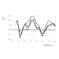
そこで、第一燃料噴射モードにおいては、プレ噴射とメイン噴射との燃料噴射間隔が所定間隔Pint2に維持される。この所定間隔Pint2は、燃料噴射弁3と蓄圧室4との相関によって決定される時間である。図5に、燃料噴射弁3からプレ噴射を行いその後メイン噴射を行ったときの、該メイン噴射の燃料噴射量のばらつきを実験によって計測した結果である。図5のグラフの横軸は、プレ噴射とメイン噴射との燃料噴射間隔であり、縦軸はメイン噴射の燃料噴射のばらつきΔQである。このばらつきは、目標とする燃料噴射量を達成する開弁時間において、燃料噴射弁3から実際に噴射された燃料噴射量と目標とする燃料噴射量との差である。
Therefore, in the first fuel injection mode, the fuel injection interval between the pre-injection and the main injection is maintained at the predetermined interval Pint2. The predetermined interval Pint2 is a time determined by the correlation between the
図5中には、プレ噴射とメイン噴射の合計燃料噴射量は同量であって、プレ噴射の燃料噴射量とメイン噴射の燃料噴射量との比率が異なる三通りの燃料噴射態様において、燃料噴射間隔に対するメイン噴射の燃料噴射量のばらつきが示されている。このように、プレ噴射とメイン噴射との関係によって、メイン噴射の燃料噴射量のばらつきは変動するが、その中でも、プレ噴射の燃料噴射量とメイン噴射の燃料噴射との比率にかかわらず、該メイン噴射の燃料噴射量のばらつきが略一定となる燃料噴射間隔が存在する。本実施例においては、燃料噴射間隔が2.5msec近傍のときに、メイン噴射の燃料噴射量のばらつきが略一定となると認められる。 In FIG. 5, the total fuel injection amount of the pre-injection and the main injection is the same amount, and the fuel injection mode is different in the ratio between the fuel injection amount of the pre-injection and the fuel injection amount of the main injection. A variation in the fuel injection amount of the main injection with respect to the injection interval is shown. As described above, the variation in the fuel injection amount of the main injection varies depending on the relationship between the pre-injection and the main injection, and among them, regardless of the ratio between the fuel injection amount of the pre-injection and the fuel injection of the main injection, There is a fuel injection interval in which the variation in the fuel injection amount of the main injection becomes substantially constant. In the present embodiment, it is recognized that the variation in the fuel injection amount of the main injection becomes substantially constant when the fuel injection interval is in the vicinity of 2.5 msec.
これは、プレ噴射において燃料噴射弁3が開弁することで蓄圧室4内に生じる圧力脈動が、蓄圧室4の形状や燃料噴射弁3と蓄圧室4との接続状態によって、略一定となることが原因の一つと考えられ得る。従って、このメイン噴射の燃料噴射量のばらつきが略一定となる燃料噴射間隔は、実際の燃料噴射弁3や蓄圧室4の状況に応じて決定される。
This is because the pressure pulsation generated in the pressure accumulating chamber 4 by opening the
ここで、第一燃料噴射モードにおける所定間隔Pint2を2.5msec近傍の時間に設定すると、プレ噴射とメイン噴射の相関にかかわらずメイン噴射の燃料噴射量のばらつきが略一定とすることが可能となる。そこで、そのばらつきを解消すべくメイン噴射における燃料噴射弁3の開弁時間を調整することで、メイン噴射の燃料噴射量をより正確に制御することが可能となる。
Here, if the predetermined interval Pint2 in the first fuel injection mode is set to a time in the vicinity of 2.5 msec, the variation in the fuel injection amount of the main injection can be made substantially constant regardless of the correlation between the pre-injection and the main injection. Become. Therefore, by adjusting the valve opening time of the
第一燃料噴射モードにおいては、プレ噴射の燃料噴射開始時期Pre_ainjは、予混合燃焼時噴射開始時期HCCI_ainjと同時期とし、該プレ噴射における燃料噴射弁3の開弁時間τ1は目標の燃料噴射量(Q=23)を噴射し得る時間である。そして、プレ噴射の終了後、所定間隔Pint2をもってメイン噴射が開始される。従って、メイン噴射の燃料噴射開始時期Main_ainjは、プレ噴射の燃料噴射開始時期Pre_ainjから、プレ噴射の開弁時間τ1と所定間隔Pint2が経過した時期となる。そのため、プレ噴射の開弁時間τ1と所定間隔Pint2次第で、メイン噴射の燃料噴射開始時期Main_ainjが圧縮行程上死点TDCの前後の何れになるかが決定される。 In the first fuel injection mode, the pre-injection fuel injection start timing Pre_ainj is the same period as the premixed combustion injection start timing HCCI_ainj, and the valve opening time τ1 of the pre-injection is the target fuel injection amount. This is the time during which (Q = 23) can be injected. And after completion | finish of pre-injection, main injection is started with the predetermined space | interval Pint2. Accordingly, the fuel injection start timing Main_ainj of the main injection is a timing when the pre-injection valve opening time τ1 and the predetermined interval Pint2 have elapsed from the fuel injection start timing Pre_ainj of the pre-injection. Therefore, depending on the valve opening time τ1 of the pre-injection and the predetermined interval Pint2, it is determined whether the fuel injection start timing Main_ainj of the main injection is before or after the compression stroke top dead center TDC.
次に、第一燃料噴射モードによる燃料噴射が開始されてから時間の経過とともに、プレ噴射とメイン噴射の各燃料噴射時期を進角側に移行する。このときプレ噴射とメイン噴射との燃料噴射間隔は、所定間隔Pint2に維持される。そして、この燃料噴射時期の進
角側への移行にともない、プレ噴射の燃料噴射量を減少させ且つメイン噴射の燃料噴射量を増加させる。
Next, the fuel injection timings of the pre-injection and the main injection are shifted to the advance side as time elapses after the fuel injection in the first fuel injection mode is started. At this time, the fuel injection interval between the pre-injection and the main injection is maintained at a predetermined interval Pint2. As the fuel injection timing shifts to the advance side, the pre-injection fuel injection amount is decreased and the main injection fuel injection amount is increased.
燃料噴射時期の進角側への移行は、メイン噴射の燃料噴射開始時期Main_ainjが、燃焼切替後に行われる通常燃焼での圧縮行程TDC近傍での燃料噴射時期と同時期となるまで行われる。これにより、燃焼切替時の燃料噴射態様が、第一燃料噴射モードから第二燃料噴射モードへと移行する。この第二燃料噴射モードによる燃料噴射の様子が、図4(c)に示されている。 The shift of the fuel injection timing to the advance side is performed until the fuel injection start timing Main_ainj of the main injection coincides with the fuel injection timing in the vicinity of the compression stroke TDC in the normal combustion performed after the combustion switching. Thereby, the fuel injection mode at the time of combustion switching shifts from the first fuel injection mode to the second fuel injection mode. The state of fuel injection in the second fuel injection mode is shown in FIG.
第二燃料噴射モードにおいては、上述したように、プレ噴射の燃料噴射量(Q=2)は、第一燃料噴射モードにおけるプレ噴射の燃料噴射量より減量され、且つメイン噴射の燃料噴射量(Q=23)は、第一燃料噴射モードにおけるメイン噴射の燃料噴射量より増量される。そして、メイン噴射の燃料噴射開始時期Main_ainjは、燃焼切替後の通常燃焼での圧縮行程TDC近傍での燃料噴射時期と同時期であって、プレ噴射とメイン噴射との燃料噴射間隔は所定間隔Pint2である。従って、プレ噴射の燃料噴射開始時期Pre_ainjは、メイン噴射の燃料噴射開始時期Main_ainjより、プレ噴射の開弁時間τ2と所定間隔Pint2前の時期となる。 In the second fuel injection mode, as described above, the fuel injection amount (Q = 2) of the pre-injection is reduced from the fuel injection amount of the pre-injection in the first fuel injection mode, and the fuel injection amount of the main injection ( Q = 23) is increased from the fuel injection amount of the main injection in the first fuel injection mode. The fuel injection start timing Main_ainj of the main injection is the same period as the fuel injection timing in the vicinity of the compression stroke TDC in the normal combustion after the combustion switching, and the fuel injection interval between the pre-injection and the main injection is a predetermined interval Pint2. It is. Therefore, the pre-injection fuel injection start timing Pre_ainj is a time before the pre-injection valve opening time τ2 and the predetermined interval Pint2 from the main injection fuel injection start timing Main_ainj.
以上より、第二燃料噴射モードは、予混合燃焼時の燃料噴射態様に近い第一燃料噴射モードから、通常燃焼時の燃料噴射態様により近づいた燃料噴射態様と言い得る。この第二燃料噴射モードを経ることで、予混合燃焼から通常燃焼への燃焼切替をより円滑に行うことが可能となる。 From the above, the second fuel injection mode can be said to be a fuel injection mode that is closer to the fuel injection mode during normal combustion than the first fuel injection mode that is close to the fuel injection mode during premixed combustion. By passing through the second fuel injection mode, it becomes possible to smoothly switch the combustion from the premixed combustion to the normal combustion.
次に、図4(c)に示す第二燃料噴射モードが行われた後、図4(d)に示す通常燃焼時の燃料噴射態様へと切り替えられ、予混合燃焼から通常燃焼への燃焼切替が終了する。尚、本実施例においては、メイン噴射に加えて、該メイン噴射より早い時期のパイロット噴射が行われる。このパイロット噴射は、燃焼切替時のプレ噴射とは異なり、図5に示すメイン噴射の燃料噴射量のばらつきを可及的に抑制し得る燃料噴射間隔をメイン噴射に対して有する燃料噴射ではなく、メイン噴射による燃焼騒音を可及的に抑制し得るパイロット用燃料噴射間隔Pint0をメイン噴射に対して有する燃料噴射である。 Next, after the second fuel injection mode shown in FIG. 4 (c) is performed, the mode is switched to the fuel injection mode during normal combustion shown in FIG. 4 (d), and the combustion is switched from premixed combustion to normal combustion. Ends. In this embodiment, in addition to the main injection, pilot injection at a timing earlier than the main injection is performed. Unlike the pre-injection at the time of combustion switching, this pilot injection is not a fuel injection having a fuel injection interval that can suppress the variation in the fuel injection amount of the main injection shown in FIG. This fuel injection has a pilot fuel injection interval Pint0 that can suppress combustion noise caused by the main injection as much as possible with respect to the main injection.
従って、通常燃焼時は、パイロット噴射によって生じるメイン噴射の燃料噴射量のばらつき抑制より、メイン噴射の燃焼騒音の抑制を優先して、パイロット噴射とメイン噴射の燃料噴射間隔が設定される。そこで、パイロット噴射の燃料噴射開始時期Pilot_ainjは、メイン噴射の燃料噴射開始時期Main_ainjより、パイロット噴射の開弁時間τ3とパイロット用燃料噴射間隔Pint0前の時期となる。 Therefore, during normal combustion, the fuel injection interval between the pilot injection and the main injection is set by giving priority to the suppression of the combustion noise of the main injection over the suppression of the variation in the fuel injection amount of the main injection caused by the pilot injection. Therefore, the pilot injection fuel injection start timing Pilot_ainj is a time before the pilot injection valve opening time τ3 and the pilot fuel injection interval Pint0 from the main injection fuel injection start timing Main_ainj.
尚、本実施例においては、通常燃焼切替直後の燃料噴射量は、パイロット噴射でQ=2、メイン噴射でQ=25となり、合計でQ=27となる。これは、予混合燃焼から通常燃焼への移行の過程で、内燃機関1の機関負荷が増加していることに対応して、燃料噴射量の合計が増加したものである。
In this embodiment, the fuel injection amount immediately after the normal combustion switching is Q = 2 for pilot injection, Q = 25 for main injection, and Q = 27 in total. This is because the total fuel injection amount has increased in response to an increase in the engine load of the
図4に示すように、予混合燃焼から通常燃焼への切替時に、第一燃料噴射モードと第二燃料噴射モードによる燃料噴射態様を経ることで、メイン噴射の燃料噴射量のばらつきを可及的に抑制してより正確な燃料噴射を行い、以てより円滑な燃焼切替が可能となる。ここで、内燃機関1において予混合燃焼から通常燃焼への燃焼切り替えを行う際に、より円滑な燃焼切替を行うべく、図6に示す燃焼切替制御が行われる。以下に、燃焼切替制御について説明する。尚、本実施例における燃焼切替制御は、ECU20によって一定のサイクルで繰り返し実行されるルーチンである。
As shown in FIG. 4, when the premixed combustion is switched to the normal combustion, the fuel injection amount of the main injection can be varied as much as possible through the fuel injection modes of the first fuel injection mode and the second fuel injection mode. Therefore, more accurate fuel injection can be performed, so that smoother combustion switching can be performed. Here, when switching the combustion from the premixed combustion to the normal combustion in the
S101では、内燃機関1の機関回転速度と機関負荷で表される運転状態が、予混合燃焼領域R1に属しているか否かが判定される。該運転状態が予混合燃焼領域R1に属していると判定されるとS102へ進み、該運転状態が予混合燃焼領域R1に属していないと判定されると本制御を終了する。
In S101, it is determined whether or not the operating state represented by the engine speed and the engine load of the
S102では、S101で予混合燃焼領域R1に属していると判定された内燃機関1の運転状態が、通常燃焼領域R2に移行したか否かが判定される。即ち、内燃機関1での燃焼を予混合燃焼から通常燃焼へと切り替える条件である燃焼領域の変更が生じたかを判定する。該運転状態が通常燃焼領域R2に移行したと判定されると、S103へ進む。該運転状態が通常燃焼領域R2に移行していないと判定されると、本制御を終了する。
In S102, it is determined whether or not the operating state of the
S103では、内燃機関1での燃焼を予混合燃焼から通常燃焼に切り替える際の遷移時間Tsを算出する。この遷移時間Tsは、予混合燃焼から通常燃焼へと切り替わる際の燃焼の遷移状態における、上述した第一燃料噴射モードと第二燃料噴射モードとが行われる時間である。本制御においては、遷移時間Tsは、図7に示すようにアクセル開度センサ26から得られるアクセル開度と、クランクポジションセンサ25の検出値から算出される機関回転速度に基づいて算出される。即ち、本制御においては、遷移時間Tsは固定値ではなく可変制御される。
In S103, a transition time Ts when the combustion in the
具体的には、アクセル開度および/または機関回転速度が大きくなるに従い、内燃機関1に対してより急激な加速が要求されていると判断され、アクセル開度および/または機関回転速度が大きくなるに従い、遷移時間Tsが短くなるように設定される。即ち、第一燃料噴射モードおよび第二燃料噴射モードの燃料噴射が行われる時間が、内燃機関1に対して要求される加速に応じて直ちに制御されることになる。その結果、急加速時は遷移時間Tsをより短くすることでより短時間で通常燃焼に移行する。急加速時は予混合燃焼時間が短いため、気筒2内に残留するEGRガス量が比較的少ない。従って、前述のように遷移時間Tsをより短く設定することが可能である。また、急加速時に遷移時間Tsに比較的長い時間を設定すると、EGRガスが比較的少ない状態においてプレ噴射を伴う第一燃料噴射モードおよび第二燃料噴射モードの燃料噴射が行われるため、燃焼状態が悪化しスモークの発生が顕著となる。そこで、S103における遷移時間Tsの可変制御が有用である。S103の処理が終了すると、S104へ進む。
Specifically, as the accelerator opening and / or the engine speed increases, it is determined that more rapid acceleration is required for the
S104では、図4(b)に示した第一燃料噴射モードによる燃料噴射が開始される。即ち、燃料噴射がプレ噴射とメイン噴射の二段で構成され、且つその燃料噴射間隔が所定間隔Pint2に維持される。ここで、所定間隔Pint2は、Pint2算出用の制御マップから算出される。該制御マップは、内燃機関1の機関回転速度をパラメータとして、各機関回転速度に対応する所定間隔Pint2が格納される制御マップである。
In S104, fuel injection in the first fuel injection mode shown in FIG. 4B is started. That is, the fuel injection is composed of two stages of pre-injection and main injection, and the fuel injection interval is maintained at the predetermined interval Pint2. Here, the predetermined interval Pint2 is calculated from a control map for calculating Pint2. The control map is a control map in which a predetermined interval Pint2 corresponding to each engine rotation speed is stored using the engine rotation speed of the
そして、第一燃料噴射モードによる燃料噴射が開始されてから時間の経過とともに、上述したようにプレ噴射とメイン噴射は燃料噴射間隔を所定間隔Pint2に維持しながら、進角側に移行される。このとき、プレ噴射の燃料噴射量は減量されながら、メイン噴射の燃料噴射量は増量されていく。S104の処理が終了すると、S105へ進む。 Then, as time passes after the fuel injection in the first fuel injection mode is started, as described above, the pre-injection and the main injection are shifted to the advance side while maintaining the fuel injection interval at the predetermined interval Pint2. At this time, the fuel injection amount of the main injection is increased while the fuel injection amount of the pre-injection is decreased. When the process of S104 ends, the process proceeds to S105.
S105では、第一燃料噴射モードの燃料噴射における、噴射時期を除いた燃料噴射に関する制御パラメータの調整が行われる。本制御においては、該パラメータとして過給圧センサ29によって検出される過給圧の調整が行われる。具体的には、図8(a)に示す予混合燃焼制御マップにしたがって、過給圧の調整が行われる。予混合燃焼制御マップは、内燃機関1において予混合燃焼が行われているときの、機関回転速度をパラメータとして過給圧を算出するための制御マップである。
In S105, the control parameters relating to the fuel injection excluding the injection timing in the fuel injection in the first fuel injection mode are adjusted. In this control, the boost pressure detected by the
そして、第一燃料噴射モードの燃料噴射は、上述したように予混合燃焼時の燃料噴射に類似した噴射態様を有していることを鑑み、S105では予混合燃焼制御マップに従って、過給圧の調整が行われる。尚、過給圧の他に、エアフローメータ9によって検出される吸入空気量や、高圧側過給機16aの可変ノズルの開度、圧力センサ28によって検出される蓄圧室4内の圧力等も、該パラメータとして予混合燃焼制御マップに従って調整される。S105の処理が終了すると、S106へ進む。
In view of the fact that the fuel injection in the first fuel injection mode has an injection mode similar to the fuel injection during the premixed combustion as described above, in S105, the boost pressure is controlled according to the premixed combustion control map. Adjustments are made. In addition to the supercharging pressure, the intake air amount detected by the air flow meter 9, the opening of the variable nozzle of the high
S106では、第一燃料噴射モードの燃料噴射が開始されてから第一所定時間t1が経過したか否かが判定される。第一所定時間t1とは、予混合燃焼から通常燃焼への切替が行われる際に第一燃料噴射モードによる燃料噴射が継続される、予め決められた時間である。第一所定時間t1が経過したと判定されるとS107へ進み、第一所定時間t1が経過していないと判定されるとS105以降の処理が再び行われる。 In S106, it is determined whether or not a first predetermined time t1 has elapsed since the start of fuel injection in the first fuel injection mode. The first predetermined time t1 is a predetermined time during which fuel injection in the first fuel injection mode is continued when switching from premixed combustion to normal combustion is performed. When it is determined that the first predetermined time t1 has elapsed, the process proceeds to S107, and when it is determined that the first predetermined time t1 has not elapsed, the processes after S105 are performed again.
S107では、図4(c)に示した第二燃料噴射モードによる燃料噴射が開始される。即ち、第一燃料噴射モードによるプレ噴射とメイン噴射の燃料噴射時期を進角させてメイン噴射の燃料噴射時期を圧縮行程上死点近傍の時期とし、且つその燃料噴射間隔が所定間隔Pint2に維持される。このとき、上述したように、メイン噴射の燃料噴射量はプレ噴射の燃料噴射量より多い、通常燃焼時の燃料噴射態様に近い燃料噴射態様となっている。S107の処理が終了すると、S108へ進む。 In S107, fuel injection in the second fuel injection mode shown in FIG. 4C is started. That is, the fuel injection timing of the pre-injection and the main injection in the first fuel injection mode is advanced to set the fuel injection timing of the main injection to a timing near the top dead center of the compression stroke, and the fuel injection interval is maintained at the predetermined interval Pint2. Is done. At this time, as described above, the fuel injection amount of the main injection is larger than the fuel injection amount of the pre-injection, which is close to the fuel injection mode during normal combustion. When the process of S107 ends, the process proceeds to S108.
S108では、第二燃料噴射モードの燃料噴射における、噴射時期を除いた燃料噴射に関する制御パラメータの調整が行われる。本制御においては、該パラメータとして過給圧センサ29によって検出される過給圧の調整が行われる。具体的には、図8(a)に示す予混合燃焼制御マップと図8(b)に示す通常燃焼制御マップに従って、過給圧の調整が行われる。通常燃焼制御マップは、内燃機関1において通常燃焼が行われているときの、機関回転速度をパラメータとして過給圧を算出するための制御マップである。
In S108, the control parameter relating to the fuel injection excluding the injection timing in the fuel injection in the second fuel injection mode is adjusted. In this control, the boost pressure detected by the
ここで、第二燃料噴射モードの燃料噴射が行われるときは、第一燃料噴射モードの燃料噴射が最後に行われたときの過給圧であって予混合燃焼制御マップから算出された過給圧PIM_H(図9に示されている)と、移行後通常燃焼の燃料噴射が初めて行われるときに通常燃焼制御マップから予想される過給圧PIM_N(図9に示されている)とから、第二燃料噴射モードの燃料噴射が行われるときの過給圧が算出される。ここで、過給圧PIM_Nの予想は、例えば、内燃機関1の運転状態の変化から通常燃焼に移行するときの機関回転速度を推定し、その推定値に基づいて通常燃焼制御マップから過給圧PIM_Nが予想される。また、図9に示すように、第二燃料噴射モードの燃料噴射が行われるときの過給圧は、過給圧PIM_Hと過給圧PIM_Nとの間で三次曲線で表される時間なまし曲線に沿う値とする。
Here, when the fuel injection in the second fuel injection mode is performed, the supercharging pressure when the fuel injection in the first fuel injection mode is performed last is the supercharging calculated from the premixed combustion control map. From the pressure PIM_H (shown in FIG. 9) and the supercharging pressure PIM_N (shown in FIG. 9) predicted from the normal combustion control map when the fuel injection of the normal combustion after the transition is performed for the first time, A supercharging pressure when fuel injection in the second fuel injection mode is performed is calculated. Here, the prediction of the supercharging pressure PIM_N is performed by, for example, estimating the engine speed when shifting to the normal combustion from the change in the operating state of the
第二燃料噴射モードの燃料噴射が行われるときは、気筒2内に比較的多くのEGRガスが残留する状態でメイン噴射の噴射量が増量されるため、その燃焼状態は比較的不安定な状態である。そこで、上述のように時間なましが適用された過給圧PIM_Hと過給圧PIM_Nとの中間値を採用することで、過給圧を燃料噴射に適した圧力とし、以て燃焼切替時の燃焼状態の悪化を回避することが可能となる。S108の処理が終了すると、S109へ進む。
When fuel injection in the second fuel injection mode is performed, the amount of main injection is increased while a relatively large amount of EGR gas remains in the
S109では、第二燃料噴射モードの燃料噴射が開始されてから第二所定時間Ts−t1が経過したか否かが判定される。即ち、第二燃料噴射モードの燃料噴射は、遷移時間がS103で算出されたTsを超えない範囲で続けられる。第二所定時間Ts−t1が経過したと判定されるとS110へ進み、第二所定時間Ts−t1が経過していないと判定されるとS108以降の処理が再び行われる。 In S109, it is determined whether or not a second predetermined time Ts-t1 has elapsed since the start of fuel injection in the second fuel injection mode. That is, the fuel injection in the second fuel injection mode is continued in a range where the transition time does not exceed Ts calculated in S103. When it is determined that the second predetermined time Ts-t1 has elapsed, the process proceeds to S110, and when it is determined that the second predetermined time Ts-t1 has not elapsed, the processes after S108 are performed again.
S110では、図4(d)に示した通常燃焼時の燃料噴射が行われる。尚、通常燃焼時は、圧縮行程上死点近傍の時期のメイン噴射に加えて、上述したパイロット噴射が行われる。ここで、パイロット噴射とメイン噴射との燃料噴射間隔であるパイロット用燃料噴射間隔Pint0は、Pint2算出用の制御マップとは独立した制御マップである、Pint0算出用の制御マップから算出される。該制御マップは、内燃機関1の機関回転速度をパラメータとして、各機関回転速度に対応するパイロット用燃料噴射間隔Pint0が格納される制御マップである。
In S110, fuel injection during normal combustion shown in FIG. 4 (d) is performed. During normal combustion, the above-described pilot injection is performed in addition to the main injection at the timing near the top dead center of the compression stroke. Here, the pilot fuel injection interval Pint0, which is the fuel injection interval between the pilot injection and the main injection, is calculated from a control map for calculating Pint0, which is a control map independent of the control map for calculating Pint2. The control map is a control map in which the pilot fuel injection interval Pint0 corresponding to each engine speed is stored using the engine speed of the
このように、所定間隔Pint2とパイロット用燃料噴射間隔Pint0との算出用の制御マップを独立させたのは、前者はプレ噴射によるメイン噴射のばらつきを抑制するための燃料噴射間隔であり、後者はメイン噴射による燃焼騒音を抑制するための燃料噴射間隔であり、それぞれの設定目的が異なるからである。これにより、第二燃料噴射モードによる燃料噴射態様から通常燃焼時の燃料噴射態様に直ちに切り替えることが可能となり、以て通常燃焼時の燃焼騒音をより確実に抑制することが可能となる。 As described above, the control map for calculating the predetermined interval Pint2 and the pilot fuel injection interval Pint0 is independent of the former in the fuel injection interval for suppressing the variation of the main injection due to the pre-injection, and the latter is This is because it is a fuel injection interval for suppressing combustion noise due to main injection, and the setting purpose of each is different. As a result, it is possible to immediately switch from the fuel injection mode in the second fuel injection mode to the fuel injection mode during normal combustion, thereby more reliably suppressing combustion noise during normal combustion.
本制御によると、第一燃料噴射モードおよび第二燃料噴射モードによる燃料噴射を行うことで、燃料噴射量のばらつきを可及的に抑制し、より円滑な燃焼切替を行うことが可能となる。更に、予混合燃焼から通常燃焼への遷移時間Tsをアクセル開度と機関回転速度とに基づいて可変制御することで、遷移時の燃焼状態の悪化を回避することが可能となる。 According to this control, by performing fuel injection in the first fuel injection mode and the second fuel injection mode, it is possible to suppress variation in the fuel injection amount as much as possible and perform smoother combustion switching. Furthermore, by variably controlling the transition time Ts from the premixed combustion to the normal combustion based on the accelerator opening and the engine speed, it is possible to avoid deterioration of the combustion state at the time of transition.
また、上述した噴射時期を除いた燃料噴射に関する制御パラメータの調整に代えて、図10に示す制御マップに基づいた該制御パラメータの調整を行ってもよい。図10(a)は、第一燃料噴射モードおよび第二燃料噴射モードが行われるとき、即ち燃焼が遷移状態にあるときの過給圧に関する制御マップであり、アクセル開度をパラメータとして燃料噴射に適した過給圧を算出するための制御マップである。図10(b)は、予混合燃焼または通常燃焼が行われるとき、即ち燃焼が遷移状態にないときの過給圧に関する制御マップであり、燃料噴射弁3からの燃料噴射量をパラメータとして燃料噴射に適した過給圧を算出するための制御マップである。
Further, instead of adjusting the control parameters related to fuel injection excluding the injection timing described above, the control parameters may be adjusted based on the control map shown in FIG. FIG. 10A is a control map related to the supercharging pressure when the first fuel injection mode and the second fuel injection mode are performed, that is, when the combustion is in a transition state, and fuel injection is performed using the accelerator opening as a parameter. It is a control map for calculating a suitable supercharging pressure. FIG. 10B is a control map relating to the supercharging pressure when premixed combustion or normal combustion is performed, that is, when the combustion is not in a transition state, and fuel injection is performed using the fuel injection amount from the
このように、燃焼が遷移状態にあるときはアクセル開度に基づいて過給圧を算出することで、内燃機関の運転状態の変動を直ちに反映させることが可能となり、以て燃焼状態の悪化を抑制しながらより円滑な燃焼の切替を行い得る。また、燃焼が遷移状態にないときは燃料噴射量に基づいて過給圧を算出することで、内燃機関の燃焼状態を反映させ該燃焼状態に応じた過給圧を形成することが可能となる。 As described above, when the combustion is in the transition state, the boost pressure is calculated based on the accelerator opening, so that the fluctuation of the operation state of the internal combustion engine can be immediately reflected, and the deterioration of the combustion state is thereby prevented. It is possible to perform smoother switching of combustion while suppressing. In addition, when the combustion is not in the transition state, the boost pressure is calculated based on the fuel injection amount, so that the boost pressure corresponding to the combustion state can be formed by reflecting the combustion state of the internal combustion engine. .
1・・・・圧縮着火内燃機関(内燃機関)
3・・・・燃料噴射弁
7・・・・吸気枝管
8・・・・吸気管
12・・・・排気枝管
16・・・・過給機
20・・・・ECU
21・・・・EGR装置
25・・・・クランクポジションセンサ
26・・・・アクセル開度センサ
28・・・・圧力センサ
29・・・・過給圧センサ
R1・・・・予混合燃焼領域
R2・・・・通常燃焼領域
Pint2・・・・所定間隔
Pint0・・・・パイロット用燃料噴射間隔
1. Compression compression internal combustion engine (internal combustion engine)
3 .... Fuel injection valve 7 ....
21 ...
Claims (5)
前記圧縮着火内燃機関の運転状態が、該圧縮着火内燃機関で行われる燃焼に応じた燃焼領域のいずれに属しているかを判定する燃焼領域判定手段と、を備え、
前記燃焼領域判定手段によって判定される燃焼領域に応じて、前記燃料噴射弁の燃料噴射条件を制御することで、圧縮行程上死点近傍の時期より早い時期の燃料噴射によって予混合気を形成することで行われる予混合燃焼と圧縮行程上死点近傍の時期の燃料噴射によって行われる通常燃焼とを切り替えて行う圧縮着火内燃機関の燃焼切替制御システムであって、
予混合燃焼から通常燃焼への燃焼切替状態である燃焼遷移状態では、予混合燃焼時および通常燃焼時とは異なる燃料噴射である遷移時燃料噴射が行われ、且つ該遷移時燃料噴射が行われる遷移時間は、前記圧縮着火内燃機関の所定運転状態に基づいて決定され、
前記遷移時燃料噴射には、予混合燃焼時の予混合燃料噴射を、該予混合燃料噴射の燃料噴射時期近くのプレ噴射と該プレ噴射後のメイン噴射とに変更するとともに該プレ噴射の噴射量を該メイン噴射の噴射量以上とする第一燃料噴射モードと、該メイン噴射の噴射時期を通常燃焼における圧縮行程上死点近傍の燃料噴射時期に向けて移行させ、且つ該プレ噴射の噴射量を減量するとともに該メイン噴射の噴射量を増量し該メイン噴射の噴射量を該プレ噴射の噴射量より多くする第二燃料噴射モードと、が採用され、
燃料噴射時期を除く燃料噴射に関する制御パラメータは、予混合燃焼時および前記第一燃料噴射モード採用時には予混合燃焼に対応した予混合燃焼制御マップより算出され、通常燃焼時には通常燃焼に対応した通常燃焼制御マップより算出されるとともに、前記第二燃料噴射モード採用時には該予混合燃焼制御マップと該通常燃焼制御マップのそれぞれによって算出される値に時間なましが適用された中間値とされることを特徴とする圧縮着火内燃機関の燃焼切替制御システム。 A fuel injection valve that injects the fuel of the compression ignition internal combustion engine into the cylinder;
Combustion region determination means for determining which operation state of the compression ignition internal combustion engine belongs to which of the combustion regions corresponding to the combustion performed in the compression ignition internal combustion engine,
By controlling the fuel injection condition of the fuel injection valve in accordance with the combustion region determined by the combustion region determining means, the premixed gas is formed by fuel injection earlier than the timing near the top dead center of the compression stroke. A combustion switching control system for a compression ignition internal combustion engine that performs switching between premixed combustion performed in this way and normal combustion performed by fuel injection at a timing near the compression stroke top dead center,
In a combustion transition state that is a combustion switching state from premixed combustion to normal combustion, fuel injection at transition, which is fuel injection different from that at the time of premixed combustion and normal combustion, is performed, and fuel injection at the time of transition is performed The transition time is determined based on a predetermined operation state of the compression ignition internal combustion engine ,
In the fuel injection at the time of transition, the premixed fuel injection at the time of premixed combustion is changed to a pre-injection near the fuel injection timing of the premixed fuel injection and a main injection after the pre-injection, and the injection of the pre-injection The first fuel injection mode in which the amount is equal to or greater than the injection amount of the main injection, and the injection timing of the main injection is shifted toward the fuel injection timing near the top dead center of the compression stroke in normal combustion, and the injection of the pre-injection A second fuel injection mode that reduces the amount and increases the injection amount of the main injection to increase the injection amount of the main injection more than the injection amount of the pre-injection,
Control parameters related to fuel injection excluding fuel injection timing are calculated from a premixed combustion control map corresponding to premixed combustion at the time of premixed combustion and when the first fuel injection mode is adopted, and normal combustion corresponding to normal combustion at the time of normal combustion Calculated from the control map, and when the second fuel injection mode is adopted, an intermediate value obtained by applying time smoothing to the value calculated by each of the premixed combustion control map and the normal combustion control map is used. A combustion switching control system for a compression ignition internal combustion engine.
前記圧縮着火内燃機関の運転状態が、該圧縮着火内燃機関で行われる燃焼に応じた燃焼領域のいずれに属しているかを判定する燃焼領域判定手段と、を備え、
前記燃焼領域判定手段によって判定される燃焼領域に応じて、前記燃料噴射弁の燃料噴射条件を制御することで、圧縮行程上死点近傍の時期より早い時期の燃料噴射によって予混合気を形成することで行われる予混合燃焼と圧縮行程上死点近傍の時期の燃料噴射によ
って行われる通常燃焼とを切り替えて行う圧縮着火内燃機関の燃焼切替制御システムであって、
予混合燃焼から通常燃焼への燃焼切替状態である燃焼遷移状態では、予混合燃焼時および通常燃焼時とは異なる燃料噴射である遷移時燃料噴射が行われ、且つ該遷移時燃料噴射が行われる遷移時間は、前記圧縮着火内燃機関の所定運転状態に基づいて決定され、
燃料噴射時期を除く燃料噴射に関する制御パラメータは、前記燃焼遷移状態においては前記圧縮着火内燃機関のアクセル開度に基づいて決定され、該燃焼遷移状態を除く予混合燃焼時または通常燃焼時においては前記燃料噴射弁からの燃料噴射量に基づいて決定されることを特徴とする圧縮着火内燃機関の燃焼切替制御システム。 A fuel injection valve that injects the fuel of the compression ignition internal combustion engine into the cylinder;
Combustion region determination means for determining which operation state of the compression ignition internal combustion engine belongs to which of the combustion regions corresponding to the combustion performed in the compression ignition internal combustion engine,
By controlling the fuel injection condition of the fuel injection valve in accordance with the combustion region determined by the combustion region determining means, the premixed gas is formed by fuel injection earlier than the timing near the top dead center of the compression stroke. A combustion switching control system for a compression ignition internal combustion engine that performs switching between premixed combustion performed in this way and normal combustion performed by fuel injection at a timing near the compression stroke top dead center,
In a combustion transition state that is a combustion switching state from premixed combustion to normal combustion, fuel injection at transition, which is fuel injection different from that at the time of premixed combustion and normal combustion, is performed, and fuel injection at the time of transition is performed The transition time is determined based on a predetermined operation state of the compression ignition internal combustion engine ,
Control parameters relating to fuel injection excluding fuel injection timing are determined based on the accelerator opening of the compression ignition internal combustion engine in the combustion transition state, and in premixed combustion or normal combustion excluding the combustion transition state, A combustion switching control system for a compression ignition internal combustion engine, which is determined based on a fuel injection amount from a fuel injection valve.
Priority Applications (1)
| Application Number | Priority Date | Filing Date | Title |
|---|---|---|---|
| JP2005008102A JP4506474B2 (en) | 2005-01-14 | 2005-01-14 | Combustion switching control system for compression ignition internal combustion engine |
Applications Claiming Priority (1)
| Application Number | Priority Date | Filing Date | Title |
|---|---|---|---|
| JP2005008102A JP4506474B2 (en) | 2005-01-14 | 2005-01-14 | Combustion switching control system for compression ignition internal combustion engine |
Publications (2)
| Publication Number | Publication Date |
|---|---|
| JP2006194194A JP2006194194A (en) | 2006-07-27 |
| JP4506474B2 true JP4506474B2 (en) | 2010-07-21 |
Family
ID=36800465
Family Applications (1)
| Application Number | Title | Priority Date | Filing Date |
|---|---|---|---|
| JP2005008102A Expired - Fee Related JP4506474B2 (en) | 2005-01-14 | 2005-01-14 | Combustion switching control system for compression ignition internal combustion engine |
Country Status (1)
| Country | Link |
|---|---|
| JP (1) | JP4506474B2 (en) |
Citations (12)
| Publication number | Priority date | Publication date | Assignee | Title |
|---|---|---|---|---|
| JPH08218920A (en) * | 1995-02-14 | 1996-08-27 | Toyota Motor Corp | Exhaust emission control device for internal combustion engine |
| JPH0942036A (en) * | 1995-08-01 | 1997-02-10 | Denso Corp | Fuel injection control device for diesel engine |
| JPH11264335A (en) * | 1998-03-18 | 1999-09-28 | Nippon Soken Inc | Throttle valve control system for internal combustion engine |
| JPH11324764A (en) * | 1998-05-20 | 1999-11-26 | Mitsubishi Automob Eng Co Ltd | diesel engine |
| JPH11324762A (en) * | 1998-05-18 | 1999-11-26 | Toyota Motor Corp | Knocking control device for internal combustion engine |
| JP2000064911A (en) * | 1998-08-19 | 2000-03-03 | Toyota Motor Corp | Internal combustion engine |
| WO2002066813A1 (en) * | 2001-02-20 | 2002-08-29 | Isuzu Motors Limited | Fuel injection control method for diesel engine and regenerative control method for exhaust gas after treatment device |
| JP2002327638A (en) * | 2001-04-27 | 2002-11-15 | Nissan Motor Co Ltd | Control device of diesel engine |
| JP2003148222A (en) * | 2001-11-15 | 2003-05-21 | Isuzu Motors Ltd | Compression ignition type internal combustion engine |
| JP2003286880A (en) * | 2002-03-28 | 2003-10-10 | Mazda Motor Corp | Combustion control device for diesel engine |
| JP2003286876A (en) * | 2002-03-28 | 2003-10-10 | Mazda Motor Corp | Combustion control device for diesel engine |
| JP2003532827A (en) * | 2000-05-08 | 2003-11-05 | カミンス インコーポレイテッド | Multi-mode internal combustion engine and method of operating internal combustion engine |
-
2005
- 2005-01-14 JP JP2005008102A patent/JP4506474B2/en not_active Expired - Fee Related
Patent Citations (12)
| Publication number | Priority date | Publication date | Assignee | Title |
|---|---|---|---|---|
| JPH08218920A (en) * | 1995-02-14 | 1996-08-27 | Toyota Motor Corp | Exhaust emission control device for internal combustion engine |
| JPH0942036A (en) * | 1995-08-01 | 1997-02-10 | Denso Corp | Fuel injection control device for diesel engine |
| JPH11264335A (en) * | 1998-03-18 | 1999-09-28 | Nippon Soken Inc | Throttle valve control system for internal combustion engine |
| JPH11324762A (en) * | 1998-05-18 | 1999-11-26 | Toyota Motor Corp | Knocking control device for internal combustion engine |
| JPH11324764A (en) * | 1998-05-20 | 1999-11-26 | Mitsubishi Automob Eng Co Ltd | diesel engine |
| JP2000064911A (en) * | 1998-08-19 | 2000-03-03 | Toyota Motor Corp | Internal combustion engine |
| JP2003532827A (en) * | 2000-05-08 | 2003-11-05 | カミンス インコーポレイテッド | Multi-mode internal combustion engine and method of operating internal combustion engine |
| WO2002066813A1 (en) * | 2001-02-20 | 2002-08-29 | Isuzu Motors Limited | Fuel injection control method for diesel engine and regenerative control method for exhaust gas after treatment device |
| JP2002327638A (en) * | 2001-04-27 | 2002-11-15 | Nissan Motor Co Ltd | Control device of diesel engine |
| JP2003148222A (en) * | 2001-11-15 | 2003-05-21 | Isuzu Motors Ltd | Compression ignition type internal combustion engine |
| JP2003286880A (en) * | 2002-03-28 | 2003-10-10 | Mazda Motor Corp | Combustion control device for diesel engine |
| JP2003286876A (en) * | 2002-03-28 | 2003-10-10 | Mazda Motor Corp | Combustion control device for diesel engine |
Also Published As
| Publication number | Publication date |
|---|---|
| JP2006194194A (en) | 2006-07-27 |
Similar Documents
| Publication | Publication Date | Title |
|---|---|---|
| JP3972599B2 (en) | Diesel engine control device | |
| US8670918B2 (en) | Method of controlling automobile-mount diesel engine and the automobile-mount diesel engine | |
| US8050846B2 (en) | Apparatus and method for controlling engine | |
| EP2933458B1 (en) | Engine control device | |
| WO2006038601A1 (en) | Diesel engine controller | |
| US20080147300A1 (en) | Controller of internal combustion engine of compression ignition combustion type | |
| WO2010073353A1 (en) | Control device for internal combustion engine | |
| JP2000352326A (en) | Control unit for diesel engine | |
| JP4196900B2 (en) | Combustion switching control system for compression ignition internal combustion engine | |
| US10626810B2 (en) | Control apparatus and control method for diesel engine | |
| JP4525373B2 (en) | Combustion switching control system for compression ignition internal combustion engine | |
| JP4888297B2 (en) | Diesel engine exhaust gas recirculation control device | |
| US7367311B2 (en) | Control system for compression ignition internal combustion engine | |
| JP2007177783A (en) | Control device for internal combustion engine | |
| JP4506474B2 (en) | Combustion switching control system for compression ignition internal combustion engine | |
| JP2005146960A (en) | Premixed compression ignition internal combustion engine | |
| JP4914874B2 (en) | Control device for internal combustion engine | |
| JP4419860B2 (en) | Combustion control system for compression ignition internal combustion engine | |
| JP2006046299A (en) | Combustion control system for compression ignition internal combustion engine | |
| JP4419855B2 (en) | Combustion switching control system for compression ignition internal combustion engine | |
| JP2005299570A (en) | Premixed combustion control system for compression ignition internal combustion engine | |
| JP4821248B2 (en) | Combustion switching control system for compression ignition internal combustion engine | |
| JP2010138829A (en) | Automatic combustion control system of diesel engine | |
| JP2009085117A (en) | Control device of diesel engine | |
| EP1176300A2 (en) | System, method and computer program for controlling fuel injection in a diesel engine |
Legal Events
| Date | Code | Title | Description |
|---|---|---|---|
| A621 | Written request for application examination |
Free format text: JAPANESE INTERMEDIATE CODE: A621 Effective date: 20080108 |
|
| A977 | Report on retrieval |
Free format text: JAPANESE INTERMEDIATE CODE: A971007 Effective date: 20091029 |
|
| A131 | Notification of reasons for refusal |
Free format text: JAPANESE INTERMEDIATE CODE: A131 Effective date: 20091110 |
|
| A521 | Written amendment |
Free format text: JAPANESE INTERMEDIATE CODE: A523 Effective date: 20091228 |
|
| TRDD | Decision of grant or rejection written | ||
| A01 | Written decision to grant a patent or to grant a registration (utility model) |
Free format text: JAPANESE INTERMEDIATE CODE: A01 Effective date: 20100406 |
|
| A01 | Written decision to grant a patent or to grant a registration (utility model) |
Free format text: JAPANESE INTERMEDIATE CODE: A01 |
|
| A61 | First payment of annual fees (during grant procedure) |
Free format text: JAPANESE INTERMEDIATE CODE: A61 Effective date: 20100419 |
|
| FPAY | Renewal fee payment (event date is renewal date of database) |
Free format text: PAYMENT UNTIL: 20130514 Year of fee payment: 3 |
|
| FPAY | Renewal fee payment (event date is renewal date of database) |
Free format text: PAYMENT UNTIL: 20130514 Year of fee payment: 3 |
|
| FPAY | Renewal fee payment (event date is renewal date of database) |
Free format text: PAYMENT UNTIL: 20130514 Year of fee payment: 3 |
|
| LAPS | Cancellation because of no payment of annual fees |