[go: up one dir, main page]

JP4486224B2 - Scroll compressor - Google Patents

Scroll compressor Download PDF

Info

Publication number
JP4486224B2
JP4486224B2 JP2000191681A JP2000191681A JP4486224B2 JP 4486224 B2 JP4486224 B2 JP 4486224B2 JP 2000191681 A JP2000191681 A JP 2000191681A JP 2000191681 A JP2000191681 A JP 2000191681A JP 4486224 B2 JP4486224 B2 JP 4486224B2
Authority
JP
Japan
Prior art keywords
oil
refrigerating machine
bearing
scroll
machine oil
Prior art date
Legal status (The legal status is an assumption and is not a legal conclusion. Google has not performed a legal analysis and makes no representation as to the accuracy of the status listed.)
Expired - Lifetime
Application number
JP2000191681A
Other languages
Japanese (ja)
Other versions
JP2002005061A (en
Inventor
央幸 木全
勝美 広岡
進 松田
Current Assignee (The listed assignees may be inaccurate. Google has not performed a legal analysis and makes no representation or warranty as to the accuracy of the list.)
Mitsubishi Heavy Industries Ltd
Original Assignee
Mitsubishi Heavy Industries Ltd
Priority date (The priority date is an assumption and is not a legal conclusion. Google has not performed a legal analysis and makes no representation as to the accuracy of the date listed.)
Filing date
Publication date
Application filed by Mitsubishi Heavy Industries Ltd filed Critical Mitsubishi Heavy Industries Ltd
Priority to JP2000191681A priority Critical patent/JP4486224B2/en
Publication of JP2002005061A publication Critical patent/JP2002005061A/en
Application granted granted Critical
Publication of JP4486224B2 publication Critical patent/JP4486224B2/en
Anticipated expiration legal-status Critical
Expired - Lifetime legal-status Critical Current

Links

Images

Landscapes

  • Rotary Pumps (AREA)
  • Applications Or Details Of Rotary Compressors (AREA)

Description

【0001】
【発明の属する技術分野】
本発明は、空気調和機等に適用されるスクロール型圧縮機に関する。
【0002】
【従来の技術】
スクロール型圧縮機は、空気調和機や冷凍機等において、冷媒の圧縮機として広く用いられている。
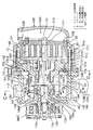
従来のスクロール型圧縮機の一例を、図12に示す。
図12において、フロントハウジング4及びリアハウジング5で構成される密閉されたハウジングHの内部にはスクロール圧縮機構Cが収納設置され、そしてフロントハウジング4の先端外形部には本スクロール圧縮機駆動動力を断続する電磁クラッチMCが設置され、これらは回転軸6を介して互いに連動直結されている。
スクロール圧縮機構Cは、固定スクロール1、旋回スクロール2、旋回スクロール2の公転旋回運動を許容するがその自転を阻止するオルダムリンク3、回転軸6を軸支するメインベアリング7等から構成される。
固定スクロール1は端板8とその内面に立設された渦巻状ラップ9を備え、端板8の中央付近には吐出ポート11が設けられている。この吐出ポート11は、吐出弁12によって開閉される。
旋回スクロール2は端板16とその内面に立設された渦巻状ラップ17とを備えている。端板16の外面に立設されたボス18内には偏心ブッシュ19が旋回軸受20を介して回転自在に嵌合され、この偏心ブッシュ19に穿設された穴に回転軸6の端部から突出する偏心ピン21が嵌合されている。
固定スクロール1と旋回スクロール2とを相互に所定距離だけ偏心させ、かつ180度だけ角度をずらして噛み合わせることによって複数個の密閉空間22が形成されている。
フロントハウジング4はリアハウジング5と一体に固定されており、このフロントハウジング4の内側端面に形成されたスラスト面23と旋回スクロール2の背面とが摺接して旋回スクロール2を支持している。
【0003】
電磁クラッチMCから動力が回転軸6に伝達されると、この回転軸6、偏心ピン21、偏心ブッシュ19、ボス18等からなる公転旋回機構を介して、旋回スクロール2はオルダムリンク3によって自転を阻止されながら公転回転半径の円軌道上を公転旋回運動する。このため、冷媒ガスは吸入ポート10から密閉されたハウジングH内に入り、ガス通路(図示せず)を通って密閉空間22内に吸入される。
そして、旋回スクロール2の公転旋回運動により密閉空間22の容積が減少するに伴って圧縮されながら中央部に至り、固定スクロール1の端板8に設けられた吐出ポート11より吐出弁12を押し開いて吐出キャビティ24に入り、ここから吐出ポート(図示せず)を経て外部に吐出される。
なお、軸封部材34により、低圧部の冷媒は外部への漏洩を阻止されている。
【0004】
【発明が解決しようとする課題】
こうしたスクロール型圧縮機においては、圧縮機内下部28に蓄積された冷凍機油は、旋回スクロール2の旋回運動によりスクロール圧縮機構Cに吸込まれ、冷媒と混合され冷媒中に融解されて、冷媒ガスの移動により圧縮機より外部に吐出され冷媒中の冷凍機油循環量が多くなって冷房性能を悪くすると共に、圧縮機内の冷凍機油量が少なくなるという問題があった。
又、一部の冷凍機油は冷媒ガスの移動により圧縮機の各部に付着するが、圧縮機の連続高速回転運転時には、回転軸6、偏心ブッシュ19、メインベアリング7、旋回スクロール2の各摺動部に、冷媒ガスに融解された冷凍機油が接触するだけでは、油潤滑が不十分で焼付きを起こす問題が有り、又、軸封部材34の油乾燥により冷媒洩れの虞があった。
【0005】
本発明は、上記事情に鑑みてなされたもので、冷凍機油量の吐出や漏れを抑制し、各摺動部を十分に潤滑させて、冷房性能を向上させるとともに信頼性及び耐久性を向上させたスクロール型圧縮機を提供すること、を目的とする。
【0006】
【課題を解決するための手段】
請求項1に記載の発明は、スクロール型圧縮機であって、フロントハウジングとリアハウジングとから構成され密閉されたハウジング内に設けられたベアリング受けと、前記フロントハウジングと前記ベアリング受けとの間に回転自在に軸支されるとともに、駆動源に接続される回転軸と、前記リアハウジングと前記ベアリング受けとの間に収容配置された一対の固定スクロールと旋回スクロールとからなり、前記回転軸の一端に設けられた偏心ピンにより駆動されるスクロール圧縮機構と、前記フロントハウジングと前記ベアリング受けとの間に形成され、該フロントハウジングに設けられた吸入ポートからの冷媒ガス中に含まれる冷凍機油を分離して溜める第1冷凍機油溜りと、前記フロントハウジングの第1冷凍機油溜り側に設けられ、前記回転軸の途中に設けられた駆動部により駆動されて前記第1冷凍機油溜りの油を前記回転軸の軸受部及び前記旋回スクロールの駆動部に給油する油ポンプ機構と、を備え、前記油ポンプ機構を、第1油ポンプと第2油ポンプとポンプカバーとで構成し、前記第1油ポンプと前記第2油ポンプとが隔壁を挟んで分離され、前記第1油ポンプを給油用とするとともに、前記第2油ポンプを前記スクロール圧縮機構の収容空間に形成された第2冷凍機油溜りに溜まった冷凍機油を前記第1冷凍機油溜りに循環させる循環用として、前記回転軸の途中に偏心部を設け、該偏心部を前記第1油ポンプ及び前記第2油ポンプの各々の冷凍機油圧縮用ロータの駆動源とし、前記フロントハウジングには、前記回転軸の位置を決定するための前記ベアリング受けを固定し、前記ポンプカバーが、前記第1油ポンプと前記第2油ポンプとを分離するための隔壁を挟んで前記フロントハウジングに固定されており、前記ポンプカバーの吐出口から吐出される冷凍機油を、前記回転軸に設けたバランサに噴射し、周辺の回転部に散布するとともに、前記フロントハウジングと前記ベアリング受けとで構成される空間下部に形成される前記第1冷凍機油溜りに貯溜された冷凍機油が前記バランサにより流動し、攪拌することを防止するためのカバーを前記ベアリング受けに固着したことを特徴とする。
【0007】
請求項に記載の発明は、請求項に記載のスクロール型圧縮機であって、前記第1油ポンプには、前記回転軸を軸芯として前記フロントハウジングに油圧縮用穴を穿設し、油圧縮用穴の周りに前記第1油ポンプの一部を構成する前記冷凍機油圧縮用ロータの高低圧油圧隔壁用の保持突起を保持するためのガイド溝を穿設し、前記第1油ポンプの低圧側には、前記フロントハウジングと前記ベアリング受けとで構成される空間下部に形成される前記第1冷凍機油溜りからの冷凍機油を導引するための吸引用第1連通孔に連通した吸込口を穿設し、前記第1油ポンプの高圧側には、吐出口を穿設し、前記回転軸に設けた第3横孔から前記回転軸の中心又は中心近辺に設けた油導通孔、第1横孔及び第2横孔を介して圧縮機の各摺動部へ冷凍機油を分配するよう連接されていることを特徴とする。
【0008】
請求項に記載の発明は、請求項1または2に記載のスクロール型圧縮機であって、前記第2油ポンプには、前記回転軸を軸芯として前記ポンプカバーに油圧縮用穴を穿設し、油圧縮用穴の周りに前記第2油ポンプの一部を構成する前記冷凍機油圧縮用ロータの高低圧油圧隔壁用の保持突起を保持するためのガイド溝を穿設し、前記第2油ポンプの低圧側には、前記リアハウジングと前記ベアリング受けとで構成される空間下部に形成される前記第2冷凍機油溜りからの冷凍機油を導引するための吸引用第2連通孔に連通した吸込口を穿設し、前記第2油ポンプの高圧側には、吐出口を穿設し、前記第1冷凍機油溜りへ冷凍機油を循環させることを特徴とする。
【0009】
請求項に記載の発明は、請求項のいずれかに記載のスクロール型圧縮機であって、前記フロントハウジングの前記回転軸を挟んだ一方には、冷凍機油の循環戻し用連通孔を穿設し、前記回転軸を挟んだ他方には、前記油ポンプ機構と連通する冷凍機油の吸引用第1連通孔及び吸引用第2連通孔を穿設し、前記吸引用第1連通孔の一方の開放端を前記第1油ポンプの吸込口に接続し、他方の開放端を前記フロントハウジングと前記ベアリング受けとで構成される空間下部に形成される前記第1冷凍機油溜りの底部に設け、前記吸引用第2連通孔の一方の開放端を前記第2油ポンプの吸込口に接続し、他方の開放端を前記リアハウジングと前記ベアリング受けとで構成される空間下部に形成される前記第2冷凍機油溜りの底部に設けている連通孔に対して穿設したことを特徴とする。
【0010】
請求項に記載の発明は、請求項に記載のスクロール型圧縮機であって、前記カバーの下部に絞り部又は隔壁部を設けたことを特徴とする。
【0011】
請求項に記載の発明は、請求項1〜のいずれかに記載のスクロール型圧縮機であって、前記スクロール圧縮機構へ冷媒を導入するための前記ベアリング受けの連通孔の冷媒通路部に、冷凍機油を分離させるための複数の小孔を穿設した板又は網目状部材を配置し、冷凍機油分離機構としたことを特徴とする。
【0012】
請求項に記載の発明は、請求項1または5に記載のスクロール型圧縮機であって、前記カバーの、前記ベアリング受けに穿設された連通孔に対応する位置には、冷媒を通すための、複数の小孔が穿設されているとともに、そのうちの少なくとも一個の小孔に網目状部材を配置し、冷凍機油分離機構としたことを特徴とする。
【0013】
請求項に記載の発明は、請求項1または5に記載のスクロール型圧縮機であって、前記カバーの上半部又は一部に、網目状あるいは波状部材を固着したことを特徴とする。
【0014】
請求項に記載の発明は、請求項1〜のいずれかに記載のスクロール型圧縮機であって、前記回転軸の一方に回転軸を軸支するための摺動軸受を設け、前記摺動軸受は、前記回転軸内に設けた冷凍機油等の潤滑油供給通路より給油を受け、前記摺動軸受に近接して軸封部材を配置したことを特徴とする。
【0015】
請求項10に記載の発明は、請求項1〜のいずれかに記載のスクロール型圧縮機であって、前記ベアリング受けと前記固定スクロールを固着し、前記固定スクロールの外周にシール材を設置し、前記リアハウジングと密着させて吐出キャビティ内部の高圧を封止したことを特徴とする。
【0016】
請求項11に記載の発明は、請求項10のいずれかに記載のスクロール型圧縮機であって、前記ポンプカバーが、前記回転軸の軸方向スラスト軸受として共用することを特徴とする。
【0017】
請求項12に記載の発明は、請求項11のいずれかに記載のスクロール型圧縮機であって、前記ポンプカバーの端面を、前記回転軸に設けた鍔にて前記油ポンプ機構からの油漏れ止めとしたことを特徴とする。
【0018】
請求項13に記載の発明は、請求項12のいずれかに記載のスクロール型圧縮機であって、前記ポンプカバーの端面にスラスト軸受を配置し、前記回転軸のスラスト軸受としたことを特徴とする。
【0019】
請求項14に記載の発明は、請求項13のいずれかに記載のスクロール型圧縮機であって、前記ポンプカバーの端面からの油漏れを防止するために前記回転軸に段を設け、前記ポンプカバーの端面に前記回転軸の段に対応する嵌合摺動部を設け、軸カバーとしたことを特徴とする。
【0020】
請求項15に記載の発明は、請求項1〜14のいずれかに記載のスクロール型圧縮機であって、前記ベアリング受けの片方の端部を前記回転軸の軸方向スラスト軸受として共用することを特徴とする。
【0021】
請求項16に記載の発明は、請求項1〜15のいずれかに記載のスクロール型圧縮機であって、前記ベアリング受けの片方の端部に鍔付き軸受を設け、鍔面をスラスト軸受として使用し、摺動軸受と一体化したことを特徴とする。
【0022】
請求項17に記載の発明は、請求項1〜16のいずれかに記載のスクロール型圧縮機であって、前記フロントハウジングと前記ベアリング受けの芯出し用として、1組以上穿設された芯出し孔、及び前記ベアリング受けと前記固定スクロールの芯出し用として、1組以上穿設された芯出し孔をそれぞれ同軸上に配置したことを特徴とする。
【0023】
請求項18に記載の発明は、請求項17に記載のスクロール型圧縮機であって、1組以上穿設された前記芯出し孔を、前記第2冷凍機油溜りから前記第1冷凍機油溜りへの連通孔とし、油循環通路に利用したことを特徴とする。
【0024】
請求項19に記載の発明は、請求項17に記載のスクロール型圧縮機であって、複数個のボルトにより、前記フロントハウジングと前記ベアリング受けと前記固定スクロールを共締めしたことを特徴とする。
【0025】
請求項20に記載の発明は、請求項19のいずれかに記載のスクロール型圧縮機であって、前記第1油ポンプの高圧側吐出口を、前記軸封部材の近傍位置に設置したことを特徴とする。
【0026】
【発明の実施の形態】
以下、本発明に係るスクロール型圧縮機の第1乃至第3の実施の形態について、図1乃至図11を用いて説明する。
【0027】
[第1の実施形態]
先ず、第1の実施形態について、図1乃至図8を用いて説明する。
このスクロール型圧縮機は、密閉されたハウジング1H内に、スクロール圧縮機構1Cを構成する固定スクロール101と旋回スクロール102とを設け、電磁クラッチ1MCに接続された回転軸106の偏心ピン121により旋回スクロール102に駆動力を伝達して冷媒の圧縮を行うスクロール型圧縮機において、密閉されたハウジング1Hを、フロントハウジング104と、これに0リング等のシール部材114と、ボルト113によって締結されたリアハウジング105と、から構成するものである。
【0028】
電磁クラッチ1MCは、図示しないエンジンによりベルト駆動され、旋回スクロール102に駆動力を伝達する。なお、電磁クラッチ1MCを省略して、回転軸106を電動機などの駆動源に直接接続してもよい。
【0029】
フロントハウジング104には、冷媒の吸入ポート110が穿設されており、回転軸106への潤滑油である冷凍機油の循環戻し用連通孔104aが、回転軸106を挟んで一方に穿設されている。また、回転軸106を挟んだ他方には、第1油ポンプ140と第2油ポンプ141で構成される油ポンプ機構Pへの冷凍機油の吸引用第1連通孔104b及び吸引用第2連通孔104cが穿設されている。
吸引用第1連通孔104bは、フロントハウジング104とベアリング受け151とで構成される空間下部に形成される第1冷凍機油溜り2Hから冷凍機油を吸い出すために穿設されたもので、一方の開放端は第1油ポンプ140の吸込口104gに接続され、他方の開放端104b1は第1冷凍機油溜り2Hの底部に設けられている。
また、吸引用第2連通孔104cは、リアハウジング105とベアリング受け151とで構成される空間下部に形成される第2冷凍機油溜り3Hから冷凍機油を吸い出すために穿設されたもので、一方の開放端は第2油ポンプ141の吸込口142gに接続され、他方の開放端は第2冷凍機油溜り3Hの底部に設けているベアリング受け151の連通孔151bに対して穿設されている。
更に、連通孔151bは、固定スクロール101の下部に穿設された連通孔101aに連通されている。
【0030】
吸引用第1連通孔104b及び吸引用第2連通孔104cの途中経路の、加工用に開けられた部分は、止め栓145及び146で各々閉止されている。
又、フロントハウジング104には、回転軸106の位置を設定するためのベアリング受け151がボルト152によって固定され、更に、油ポンプ機構Pを構成するポンプカバー142が第1油ポンプ140と第2油ポンプ141を分離するための隔壁143を挟んでボルト144にて固定されている。尚、前記ポンプカバー142には循環戻し用連通孔104aに接続した連通孔142aが穿設されている。
ベアリング受け151には、スクロール圧縮機構1Cへ冷媒を導入するための連通孔151aが穿設され、下部には第2冷凍機油溜り3Hとフロントハウジング104に穿設された吸引用第2連通孔104cに連通させるための連通孔151bが穿設され、偏心ピン121から吐出される冷凍機油を第1冷凍機油溜り2Hへ戻すための連通孔151cが穿設されている。
【0031】
連通孔151aの冷媒通路部には、冷凍機油を分離させるための複数の小孔を穿設した板又は網目状部材162が配置され、冷凍機油分離機構を構成している。また、ベアリング受け151には、固定スクロール101がボルト148にて固着されている。
また、図1及び図8に示すように、フロントハウジング104には吐出口を兼ねた芯出し用孔104hが、ベアリング受け151には芯出し用孔151hが、各々1組以上となるように穿設されており、ベアリング受け151には芯出し用孔151jが、固定スクロール101には芯出し用孔101jが、各々を1組以上となるように穿設されており、組立時の芯出し治具の使用に供するようになっている。
【0032】
第1冷凍機油溜り2Hに貯溜された冷凍機油は、回転軸106の途中に設けられた鍔106gに固着されたバランサ153により攪拌流動され、冷媒中の冷凍機油溶解量が多くなることを防止するためのカバー154が、ボルト155にてベアリング受け151に固着されている。
【0033】
鍔106gは、ポンプカバー142の端面及びベアリング受け151の端面と摺動接触し、冷凍機油を保持するように配置されている。
なお、カバー154は、図5に示す如く、スクロール圧縮機構1Cへ冷媒を導入するためのベアリング受け151に穿設された連通孔151aに冷媒を通すための孔154aが穿設されているが、図6に示す如く、下部に絞り部又は隔壁部154bを設け冷凍機油の攪拌範囲を更に限定し少なくしても良い。
又、スクロール圧縮機構1Cへ冷媒を導入するためのベアリング受け151に穿設された連通孔151aに冷媒を通すための孔は小孔154cを複数穿設して、冷凍機油分離機構用の複数の小孔を穿設した板又は網目状部材162の設置を省略しても良い。
更に、カバー154の他の一例として、図7に示す如く、カバー154の上半部又は一部に網目状あるいは波状板部材159を固着し、又、スクロール圧縮機構1Cへ冷媒を導入するためのベアリング受け151に穿設された連通孔151aに冷媒を通すための孔154aに網目状部材158を固着しても良い。
【0034】
固定スクロール101と旋回スクロール102の旋回運動により製造された高圧冷媒を、固定スクロール101の端板108の中央又は中央近傍に穿設した吐出ポート111に装着された吐出弁112を経て、吐出キャビティ124に導引し、圧縮機外に吐出するために、リアハウジング105には吐出ポート125が穿設されている。
なお、前記固定スクロール101の外周には、0リング等のシール材126が設置されており、リアハウジング105と密着させて、吐出キャビティ124内部の高圧を封止している。
【0035】
回転軸106の軸中心又は中心近傍には偏心ピン121の軸端面より油導通孔106aが穿設されている。また、油導通孔106aに対し、摺動軸受107及び130に給油するための第1横孔106b及び第2横孔106cが開孔され、第1油ポンプ140より給油受けするための第3横孔106dが開孔されている。これら各々の第1横孔106b、第2横孔106c、第3横孔106dは、油導通孔106aに連通している。
なお、回転軸106の偏心ピン121と旋回スクロール102は、偏心ブッシュ119及び旋回軸受120にて回転保持されており、回転軸106の他端部近くには摺動軸受130に近接して軸封部材134が設けられ、密閉保持されている。また、回転軸106の途中には偏心部106eが設けられ、第1油ポンプ140及び第2油ポンプ141の駆動源となっている。
【0036】
第1油ポンプ140には、回転軸106を軸芯としてフロントハウジング104に油圧縮用穴104eが穿設され、油圧縮用穴104eの周りには第1油ポンプ140の一部を構成する冷凍機油圧縮用ロータ156の高低圧油圧隔壁用の保持突起156aを保持するためのガイド溝104fが穿設されている。
また、第1油ポンプ140の低圧側には、第1冷凍機油溜り2Hからの冷凍機油を導引するための吸引用第1連通孔104bに連通した吸入口104gが穿設されている。
更に、第1油ポンプ140の高圧側には、吐出口104hが穿設され、回転軸106に設けられた第3横孔106dから、各摺動部へ分配されるよう連接されている。
【0037】
第2油ポンプ141には、回転軸106を軸芯としてポンプカバー142に油圧縮用穴142eが穿設され、油圧縮用穴142eの周りに第2油ポンプ141の一部を構成する冷凍機油圧縮用ロータ157の高低圧油圧隔壁用の保持突起157aを保持するためのガイド溝142fを穿設し、第2油ポンプ141の低圧側には第2冷凍機油溜り3Hからの冷凍機油を導引するための吸引用第2連通孔104cに連通した吸込口142gが穿設されている。
第2油ポンプ141の高圧側には、吐出口142hが穿設されており、第1冷凍機油溜り2Hへ冷凍機油を循環させている。
【0038】
電磁クラッチ1MCが接続状態になった時、図示しないエンジンによりベルト駆動され、電磁クラッチ1MCに接続された回転軸106の偏心ピン121の偏心回転により、スクロール圧縮機構1Cを構成する旋回スクロール102が旋回運動を行う。吸入ポート110より吸引された冷媒は、ベアリング受け151の連通孔151aに設けられた小孔を穿設した板又は網目状部材162、あるいはカバー154に設けた冷媒を通すための小孔154c又は網目状部材158により冷凍機油を分離し、冷媒ガスのみ通過させ、固定スクロール101との密閉空間に導引された冷媒ガスは圧縮されて、吐出ポート111より吐出弁112を押し開き吐出キャビティ124に入り、吐出ポート125から圧縮機外部へ吐出される。この時、吐出キャビティ124内部の高圧は、固定スクロール101の外周に設けられた0リング等のシール材126により、低圧側と隔絶されている。
【0039】
この時、回転軸106に設けられた偏心部106eも偏心回転運動を行う。偏心部106eは、第1油ポンプ140及び第2油ポンプ141に内蔵された冷凍機油圧縮用ロータ156及び157を偏心回転運動させる。このため、第1油ポンプ140の場合、冷凍機油圧縮用ロータ156の外周は、油圧縮用穴104eの内周を摺動しながら、吸込口104gに連接したフロントハウジング104に穿設された吸引用第1連通孔104bを経由して、第1冷凍機油溜り2Hの下部に蓄積された冷凍機油を吸引し、吐出口104h側に圧縮して送り出すポンプ作用を行う。
【0040】
吐出口104hから吐出された冷凍機油は、回転軸106に設けられた第3横孔106dから油導通孔106aに入り、第1横孔106b及び第2横孔106cにも分配されるが、回転軸106の軸端の開放口より偏心ブッシュ119及び旋回軸受120へ給油される。給油後の冷凍機油は、ベアリング受け151に設けられた連通孔151cより第1冷凍機油溜り2Hへ循環される、一部は旋回スクロール102の摺動部、ベアリング受け151と固定スクロール101の合わせ目を経て第2冷凍機油溜り3Hへ循環される。
又、第1横孔106bからは摺動軸受107へ給油され、給油後の冷凍機油は摺動軸受107の端部より第1冷凍機油溜り2Hへ循環され、一部は第2冷凍機油溜り3Hへ循環される。
更に、第2横孔106cからは摺動軸受130へ給油され、前記摺動軸受130の軸端から流出した冷凍機油は、軸封部材134へ給油されると共にフロントハウジング104に設けられた循環戻し用連通孔104a及びポンプカバー142に設けられた連通孔142aを経て第1冷凍機油溜り2Hへ循環される。
【0041】
一方、第2油ポンプ141の場合は、冷凍機油圧縮用ロータ157の外周は油圧縮用穴142eの内周を摺動しながら、吸込口142gに連接したフロントハウジング104に穿設された吸引用第2連通孔104c、ベアリング受け151に穿設された連通孔151b及び固定スクロール101下部に穿設された連通孔101aを経由して第2冷凍機油溜り3Hの下部に蓄積された冷凍機油を吸引し、吐出口142h側に圧縮して送り出すポンプ作用を行う。
吐出口142hから吐出される冷凍機油は、回転軸106の途中に設けられた鍔106gとポンプカバー142の端面との摺動部を経て、第1冷凍機油溜り2Hへ循環する。
回転軸106が回転し、回転軸106の途中に設けられた鍔106gに固着されたバランサが回転した時、カバー154により連通孔151a及び第1冷凍機油溜り2Hへの直接攪拌が抑止されるため、冷凍機油がスクロール圧縮機構1Cへ入り込むことを抑制し、又、第1冷凍機油溜り2H内の攪拌防止により油ポンプ機構Pの機能を発揮しやすくしている。
なお、カバー154の下部に絞り部又は隔壁部154bを設けた場合は、絞り部又は隔壁部154bにより横方向への攪拌流動性の強さを弱くすることができるので、第1冷凍機油溜り2Hに貯溜された冷凍機油に対しバランサ153の回転影響を更に少なくすることができる。
又、回転軸106の途中に設けられた鍔106gは、ポンプカバー142の端面及びベアリング受け151の端面と摺動接触しているため、回転軸106とポンプカバー142の隙間から油ポンプ機構で加圧された冷凍機油の洩れを少なくすると共に、摺動軸受107から還流された冷凍機油を保持しやすくしている。同時に、ポンプカバー142の端面とベアリング受け151の端面は、鍔106gによるスラスト荷重を支持している。
【0042】
以上により、リアハウジング105とベアリング受け151で構成される空間下部に形成される第2冷凍機油溜り3Hの冷凍機油は、ベアリング受け151と固定スクロール101の合わせ目より浸出して貯溜されるが、ポンプ機構Pにより第1冷凍機油溜り2H側に循環されるので、第2冷凍機油溜り3Hに貯油される量が少なくなり、スクロール圧縮機構1Cに吸込まれて冷媒と混合され、冷媒に融解されて、冷媒ガスの移動により圧縮機より外部に吐出される量を少なくすることができる。このため、冷媒中の冷凍機油循環量が多くなって冷房性能を悪くすると共に圧縮機内の冷凍機油量が少なくなる、といった問題がなくなり、更にシール部材114からの冷凍機油漏れが防止できる。
【0043】
又、油ポンプ機構Pにより圧縮機内部の軸封部、摺動部及び軸受部に冷凍機油の供給が可能となり、高速運転時に油潤滑が不十分で焼付きが発生することを防止できると共に、軸封部の乾燥が防止でき冷媒洩れが防止できる。
なお、摺動軸受130に近接して軸封部材134を配置したことにより、第2横孔106cから給油された冷凍機油が摺動軸受130の軸端からサイドフローと呼ばれる冷凍機油の排出が行われ、軸封部材134に対し特別な給油装置を設けることなく軸封部材の乾燥防止ができる。
【0044】
更に、カバー154の上半部又は一部に設けた網目状部材159により圧縮機内に吸引された冷媒は、溶解されている冷凍機油を分離し、熱交換器へ送出される冷媒中の冷凍機油の含油率を低下させて熱交換率を高める事ができると共に、分離した冷凍機油を圧縮機内に留めることにより圧縮機の潤滑性を高めると共に省動力化及び耐久性を高めることができる。
【0045】
[第2の実施形態]
本発明に係るスクロール圧縮機の第2の実施形態について、図9を用いて説明する。
図9において、回転軸206は鍔付き摺動軸受207及び230にて軸支されている。又、回転軸206には、ポンプカバー242の端部からの冷凍機油漏れを防止するための段206fを設け、ポンプカバー242の端面には、段206fに対応した嵌合摺動部242fを穿設し軸カバーとする。
回転軸206のバランサ253取付け用鍔206gの端面は、鍔付き摺動軸受207の鍔端面と摺動するよう配置する。又、回転軸206のポンプ機構2Pを駆動させるための偏心部206eの端面は、鍔付き摺動軸受230の鍔端面と摺動するよう配置する。
【0046】
回転軸206に段206fを設け、ポンプカバー242に嵌合部242fを設け、これらが摺動接触しているので回転軸206とポンプカバー242の隙間から油ポンプ機構2Pで加圧された冷凍機油の漏れを少なくし圧力低下を防止することができる。
又、鍔付き摺動軸受230を鍔付きとしたことにより、ポンプカバー242側と同様に回転軸206の偏心部206eの端部と摺動接触しているので、油ポンプ機構2Pで加圧された冷凍機油の漏れを少なくし、圧力低下を防止すると共に、回転軸206のスラスト荷重を軸支することができる。
更に、鍔付き摺動軸受207を鍔付きとしたことにより、回転軸206の鍔206gの端面に摺動接触させることにより回転軸206の反対方向にかかるスラスト荷重を軸支する事ができる。
【0047】
以上により、油ポンプ機構2Pからの冷凍機油漏れを少なくして圧力低下を防止すると共に、回転軸206にかかる両方向のスラスト荷重を鍔付き摺動軸受230及び207の鍔部で軸支することにより回転を滑らかにするとともに耐久性を高めることができる。
【0048】
[第3の実施形態]
本発明に係るスクロール圧縮機の第3の実施形態について、図10及び図11を用いて説明する。
図10において、油ポンプ機構3Pはフロントハウジング304と回転軸306の偏心部306eと第1油ポンプ340と隔壁343と第2油ポンプ341と端面にメタル軸受等のスラスト軸受332を配置したポンプカバー342とから構成され、第1油ポンプ340の吐出口(図示せず)はフロントハウジング304に設けた冷凍機油循環流入用連通孔304aに連通し、回転軸306に設けた第3横孔306hに開孔している。
なお、回転軸306の偏心ピン321と旋回スクロール302は偏心ブッシュ319及び旋回軸受320にて回転保持されおり、回転軸306の他端部近くには摺動軸受330に近接して軸封部材334が設けられ密閉保持されている。回転軸306には軸中心又は中心近傍に偏心ピン321の軸端面より油導通孔306aが穿設され、又、前記導通孔306aに対し、鍔付き摺動軸受307及び摺動軸受330に給油するための第1横孔306b及び第2横孔306cが開孔され、各々の第3横孔306h、第1横孔306b、第2横孔306cは前記油導通孔306aに連通している。
又、回転軸306のバランサ353取付け用の鍔306gの端面は、前記摺動軸受307の鍔端面及びポンプカバー342に設けられたスラスト軸受332と摺動するよう配置する。
【0049】
フロントハウジング304には回転軸306の位置を設定するためのベアリング受け351と固定スクロール301がボルト352によって共締めにて固定されている。
又、図10及び図11において、フロントハウジング304とベアリング受け351の芯出し用孔304h及び351hを1組以上穿設し、ベアリング受け351と固定スクロール301の芯出し用孔351j及び301jを1組以上穿設し、前記芯出し用孔304h、351h、351j及び301jを同軸上に配置する。
なお、フロントハウジング304に複数のネジ304kを作成し、ベアリング受け351と固定スクロール301に、ネジ304kと同軸上に図示しない貫通孔を穿設し、フロントハウジング304とベアリング受け351と固定スクロール301との3部品共締めする。
更に、圧縮機底部に設けた前記芯出し用孔304hは、第2油ポンプ341の吸入口(図示せず)に連通した吸引用第2連通孔304cに連通し、冷凍機油溜り33Hと連通させ、上記第1の実施形態に示す連通孔151b及び101aの代用とする。
【0050】
第1油ポンプ340から吐出された冷凍機油は、フロントハウジング304に設けた冷凍機油循環流入用連通孔304aより回転軸306に設けた第3横孔306hに入り、回転軸306の軸中心又は中心近傍に設けられた油導通孔306aを介して、油導通孔306aに連通した第1横孔306bより鍔付き摺動軸受307へ給油され、又、同様に第2横孔306cより摺動軸受330に給油され、更に油導通孔306aの開孔端部より、旋回スクロール302と偏心ピン321と偏心ブッシュ319と旋回軸受320とへ給油される。
又、回転軸306に鍔306gを設け、ポンプカバー342の端面にメタル軸受等のスラスト軸受332を配置し摺動接触させているので、回転軸306のスラスト荷重を軸支することができる。
更に、摺動軸受307を鍔付きとしたことにより、上記第2の実施形態と同様に、回転軸306の鍔306gの端面に摺動接触させることにより回転軸306の反対方向にかかるスラスト荷重を軸支する事ができる。
【0051】
以上により、各摺動部に円滑な給油を行い、油ポンプ機構3Pからの冷凍機油漏れを少なくして圧力低下を防止すると共に、回転軸306にかかる両方向のスラスト荷重を鍔付き摺動軸受307の鍔部で軸支することにより回転を滑らかにするとともに耐久性を高めることができる。
又、フロントハウジング304とベアリング受け351の芯出し用孔304h及び351hを1組以上穿設し、ベアリング受け351と固定スクロール301の芯出し用孔351j及び301jを1組以上穿設し、前記芯出し用孔304h、351h、351j及び301jを同軸上に配置し、フロントハウジング304に複数のネジ304kを作成し、ベアリング受け351と固定スクロール301に、ネジ304kと同軸上に図示しない貫通孔を穿設し、フロントハウジング304とベアリング受け351と固定スクロール301との3部品共締めする為、上記第1の実施形態にてフロントハウジング104とベアリング受け151をボルト152にて固定し、ベアリング受け151と固定スクロール101をボルト148にて固定しているのに比べ簡略化できる。
更に、圧縮機底部に設けた前記芯出し用孔304hは、第2油ポンプ341の吸入口(図示せず)に連通した吸引用第2連通孔304cに連通し、冷凍機油溜り33Hと連通させ、上記第1の実施形態に示す連通孔151b及び101aの代用し加工を省略できる。
【0052】
【発明の効果】
以上説明したように、本発明に係るスクロール型圧縮機によれば、冷凍機油量の吐出や漏れを抑制し、各摺動部を十分に潤滑させて、冷房性能を向上させるとともに信頼性及び耐久性を向上させたスクロール型圧縮機を提供することができる。
【図面の簡単な説明】
【図1】 本発明に係るスクロール型圧縮機の第1の実施形態を示す図であって、スクロール型圧縮機の断面図である。
【図2】 図1におけるA−A線断面矢視図である。
【図3】 図1におけるB−B線断面矢視図である。
【図4】 図1におけるC−C線断面矢視図である。
【図5】 図1におけるポンプカバーの一例を示す図であって、(a)は正面図、(b)は(a)におけるD−D線断面矢視図である。
【図6】 同ポンプカバーの他の一例を示す図であって、(a)は正面図、(b)は(a)におけるE−E線断面矢視図である。
【図7】 ポンプカバーの更に他の一例を示す側面図である。
【図8】 図1におけるG線断面矢視図である。
【図9】 本発明に係るスクロール型圧縮機の第2の実施形態を示す図であって、スクロール型圧縮機を部分的に拡大した断面図である。
【図10】 本発明に係るスクロール型圧縮機の第3の実施形態を示す図であって、スクロール型圧縮機の断面図である。
【図11】 図10におけるH−H線断面矢視図である。
【図12】 従来のスクロール型圧縮機の一例を示す図であって、スクロール型圧縮機の断面図である。
【符号の説明】
1C スクロール圧縮機構
1H ハウジング
1MC 電磁クラッチ
P 油ポンプ機構
101 固定スクロール
101a 連通孔
101j 芯出し用孔
102 旋回スクロール
104 フロントハウジング
104a 循環戻し用連通孔
104b1 開放端
104b 吸引用第1連通孔
104c 吸引用第2連通孔
104e 油圧縮用穴
104f ガイド溝
104g 吸込口
104h 吐出口(芯出し用孔)
105 リアハウジング
106 回転軸
106a 油導通孔
106b 第1横孔
106c 第2横孔
106d 第3横孔
106e 偏心部
106g 鍔
107 摺動軸受
108 端板
110 吸入ポート
111 吐出ポート
112 吐出弁
113 ボルト
114 シール部材
119 偏心ブッシュ
120 旋回軸受
121 偏心ピン
124 吐出キャビティ
125 吐出ポート
126 シール材
130 摺動軸受
134 軸封部材
140 第1油ポンプ
141 第2油ポンプ
142 ポンプカバー
142a 連通孔
142e 油圧縮用穴
142f ガイド溝
142g 吸込口
142h 吐出口
143 隔壁
144 ボルト
145 止め栓
146 止め栓
148 ボルト
151 ベアリング受け
151a 連通孔
151b 連通孔
151j 芯出し用孔
152 ボルト
153 バランサ
154 カバー
154a 孔
154b 隔壁部
154c 小孔
155 ボルト
156 冷凍機油圧縮用ロータ
156a 保持突起
157 冷凍機油圧縮用ロータ
157a 保持突起
158 網目状部材
159 波状板部材
162 網目状部材
2H 第1冷凍機油溜り
2P 油ポンプ機構
206 回転軸
206e 偏心部
206f 段
206g 鍔
207 鍔付き摺動軸受
230 鍔付き摺動軸受
242 ポンプカバー
242f 嵌合部
253 バランサ
3H 第2冷凍機油溜り
33H 冷凍機油溜り
3P 油ポンプ機構
301 固定スクロール
301j 芯出し用孔
302 旋回スクロール
304 フロントハウジング
304a 冷凍機油循環流入用連通孔
304c 吸引用第2連通孔
304h 芯出し用孔
304k ネジ
306 回転軸
306a 油導通孔
306b 第1横孔
306c 第2横孔
306e 偏心部
306g バランサ取付用鍔
306h 第3横孔
319 偏心ブッシュ
320 旋回軸受
321 偏心ピン
332 スラスト軸受
334 軸封部材
340 第1油ポンプ
341 第2油ポンプ
342 ポンプカバー
343 隔壁
352 ボルト
353 バランサ
[0001]
BACKGROUND OF THE INVENTION
The present invention relates to a scroll compressor applied to an air conditioner or the like.
[0002]
[Prior art]
Scroll compressors are widely used as refrigerant compressors in air conditioners and refrigerators.
An example of a conventional scroll compressor is shown in FIG.
In FIG. 12, a scroll compression mechanism C is housed and installed in a sealed housing H constituted by a front housing 4 and a rear housing 5, and the driving force for driving the scroll compressor is supplied to the outer end of the front housing 4. Intermittent electromagnetic clutches MC are installed, and these are directly coupled to each other via a rotating shaft 6.
The scroll compression mechanism C is composed of a fixed scroll 1, a turning scroll 2, an Oldham link 3 that allows the revolution turning motion of the turning scroll 2 but prevents its rotation, a main bearing 7 that supports the rotation shaft 6, and the like.
The fixed scroll 1 includes an end plate 8 and a spiral wrap 9 erected on the inner surface thereof, and a discharge port 11 is provided near the center of the end plate 8. The discharge port 11 is opened and closed by a discharge valve 12.
The orbiting scroll 2 includes an end plate 16 and a spiral wrap 17 standing on the inner surface thereof. An eccentric bush 19 is rotatably fitted in a boss 18 erected on the outer surface of the end plate 16 via a swivel bearing 20, and a hole formed in the eccentric bush 19 is inserted into the hole from the end of the rotary shaft 6. A protruding eccentric pin 21 is fitted.
A plurality of sealed spaces 22 are formed by causing the fixed scroll 1 and the orbiting scroll 2 to be eccentric from each other by a predetermined distance and engaged with each other while shifting the angle by 180 degrees.
The front housing 4 is fixed integrally with the rear housing 5, and the thrust surface 23 formed on the inner end surface of the front housing 4 and the back surface of the orbiting scroll 2 are in sliding contact with each other to support the orbiting scroll 2.
[0003]
When power is transmitted from the electromagnetic clutch MC to the rotary shaft 6, the orbiting scroll 2 is rotated by the Oldham link 3 through a revolution turning mechanism comprising the rotary shaft 6, the eccentric pin 21, the eccentric bush 19, and the boss 18. While being blocked, it makes a revolution orbit on a circular orbit of revolution radius. Therefore, the refrigerant gas enters the sealed housing H from the suction port 10 and is sucked into the sealed space 22 through a gas passage (not shown).
Then, as the volume of the sealed space 22 decreases due to the revolving orbiting motion of the orbiting scroll 2, the center portion is reached while being compressed, and the discharge valve 12 is pushed open from the discharge port 11 provided on the end plate 8 of the fixed scroll 1. Then, the liquid enters the discharge cavity 24 and is discharged outside through a discharge port (not shown).
Note that the shaft seal member 34 prevents the refrigerant in the low pressure portion from leaking to the outside.
[0004]
[Problems to be solved by the invention]
In such a scroll compressor, the refrigerating machine oil accumulated in the lower part 28 in the compressor is sucked into the scroll compression mechanism C by the orbiting motion of the orbiting scroll 2, mixed with the refrigerant and melted in the refrigerant, and the refrigerant gas moves. As a result, the amount of refrigerating machine oil that is discharged from the compressor to the outside increases in the refrigerant and deteriorates cooling performance, and the amount of refrigerating machine oil in the compressor decreases.
Some of the refrigerating machine oil adheres to each part of the compressor due to the movement of the refrigerant gas. During continuous high-speed rotation operation of the compressor, the sliding of the rotary shaft 6, the eccentric bush 19, the main bearing 7, and the orbiting scroll 2 is performed. If the refrigerating machine oil melted in the refrigerant gas is in contact with the part, there is a problem that oil lubrication is insufficient and seizure occurs, and there is a risk of refrigerant leakage due to oil drying of the shaft seal member 34.
[0005]
The present invention has been made in view of the above circumstances, suppresses discharge and leakage of the amount of refrigerating machine oil, sufficiently lubricates each sliding portion, improves cooling performance and improves reliability and durability. It is an object of the present invention to provide a scroll type compressor.
[0006]
[Means for Solving the Problems]
The invention according to claim 1 is a scroll compressor, comprising a front housing and a rear housing, a bearing receiver provided in a hermetically sealed housing, and the front housing Said A rotary shaft that is rotatably supported between the bearing receiver and connected to a drive source; and the rear housing; Said A scroll compression mechanism comprising a pair of fixed scrolls and orbiting scrolls accommodated between the bearing receiver and driven by an eccentric pin provided at one end of the rotary shaft, and the front housing and the bearing receiver A first refrigerating machine oil sump that is formed between and separates and stores refrigerating machine oil contained in refrigerant gas from a suction port provided in the front housing; and provided on the first refrigerating machine oil sump side of the front housing; An oil pump mechanism that is driven by a drive unit provided in the middle of the rotary shaft and supplies oil from the first refrigerator oil sump to the bearing unit of the rotary shaft and the drive unit of the orbiting scroll. The oil pump mechanism includes a first oil pump, a second oil pump, and a pump cover, and the first oil pump and the second oil pump are separated with a partition wall therebetween, and the first oil pump is The rotating shaft is used for refueling and for circulating the second oil pump in the first refrigerating machine oil sump for refrigerating machine oil accumulated in a second refrigerating machine oil sump formed in the storage space of the scroll compression mechanism. An eccentric portion is provided in the middle, and the eccentric portion is used as a drive source for the compressor oil compression rotor of each of the first oil pump and the second oil pump, and the position of the rotary shaft is determined in the front housing. And the pump cover is fixed to the front housing with a partition wall separating the first oil pump and the second oil pump, and the pump cover The refrigerating machine oil discharged from the discharge port is sprayed to a balancer provided on the rotating shaft, and is sprayed on a peripheral rotating portion, and is formed in a lower space formed by the front housing and the bearing receiver. 1 A cover for preventing the refrigerating machine oil stored in the refrigerating machine oil reservoir from flowing and stirring by the balancer is fixed to the bearing receiver. It is characterized by that.
[0007]
Claim 2 The invention described in claim 1 A scroll type compressor according to claim 1, Said The first oil pump Said Using the rotation axis as the axis Said Drill holes for oil compression in the front housing, The Around the oil compression hole Said Part of the first oil pump Said Drilling a guide groove to hold the holding projection for the high and low pressure hydraulic partition of the compressor oil compressor rotor, Said On the low pressure side of the first oil pump, Said With front housing Said Formed in the lower part of the space composed of bearing receivers Said A suction port communicating with the first communication hole for suction for drawing the refrigerating machine oil from the first refrigerating machine oil reservoir, Said A discharge port is drilled on the high pressure side of the first oil pump, Said From the 3rd side hole provided in the rotating shaft Said It is connected so that refrigeration oil may be distributed to each sliding part of a compressor through the oil conduction hole, the 1st horizontal hole, and the 2nd horizontal hole which were provided in the center of rotation axis, or the center vicinity.
[0008]
Claim 3 The invention described in claim 1 or 2 A scroll type compressor according to claim 1, Said The second oil pump Said Using the rotation axis as the axis Said Drill a hole for oil compression in the pump cover, The Around the oil compression hole Said Part of the second oil pump Said Drilling a guide groove to hold the holding projection for the high and low pressure hydraulic partition of the compressor oil compressor rotor, Said On the low pressure side of the second oil pump, Said With rear housing Said Formed in the lower part of the space composed of bearing receivers Said A suction port communicating with the second communication hole for suction for drawing the refrigerating machine oil from the second refrigerating machine oil reservoir, Said A discharge port is drilled on the high pressure side of the second oil pump, Said The refrigerating machine oil is circulated to the first refrigerating machine oil sump.
[0009]
Claim 4 The invention described in claim 1 ~ 3 A scroll compressor according to any one of Said Front housing Said On one side of the rotating shaft, a recirculation return communication hole for refrigeration oil is drilled, Said On the other side of the rotation axis, Said A first communication hole for suction and a second communication hole for suction of the refrigerating machine oil communicating with the oil pump mechanism are formed, Said One open end of the first communication hole for suction Said Connect to the suction port of the first oil pump and connect the other open end Said With front housing Said Formed in the lower part of the space composed of bearing receivers Said Provided at the bottom of the first refrigerating machine oil sump, Said One open end of the second communication hole for suction Said Connect to the suction port of the second oil pump and connect the other open end Said With rear housing Said Formed in the lower part of the space composed of bearing receivers Said The second refrigerating machine oil sump is formed in a communication hole provided at the bottom.
[0010]
Claim 5 The invention described in claim 1 A scroll type compressor according to claim 1, The cover The throttle part or the partition part was provided in the lower part of this.
[0011]
Claim 6 The invention described in claim 1 5 A scroll compressor according to any one of Said For introducing refrigerant into the scroll compression mechanism Said A plate or mesh member having a plurality of small holes for separating the refrigerating machine oil is arranged in the refrigerant passage portion of the communication hole of the bearing receiver to form a refrigerating machine oil separation mechanism.
[0012]
Claim 7 The invention described in claim 1 or 5 A scroll type compressor according to claim 1, A plurality of small holes are formed in the cover at positions corresponding to the communication holes formed in the bearing receiver, and a mesh member is formed in at least one of the small holes. To provide a refrigeration machine oil separation mechanism It is characterized by that.
[0013]
Claim 8 The invention described in claim 1 or 5 A scroll type compressor according to claim 1, The cover A mesh-like or wave-like member is fixed to the upper half or a part of.
[0014]
Claim 9 The invention described in claim 1 8 A scroll compressor according to any one of Said On one of the rotation axes The A sliding bearing for pivotally supporting the rotating shaft is provided, and the sliding bearing is Said Oil supply is received from a lubricating oil supply passage such as refrigeration oil provided in the rotary shaft, and a shaft seal member is disposed in the vicinity of the sliding bearing.
[0015]
Claim 10 The invention described in claim 1 9 A scroll compressor according to any one of Said With bearing receiver Said Secure the fixed scroll, Said Install sealing material on the outer periphery of the fixed scroll, Said The high pressure inside the discharge cavity is sealed by being in close contact with the rear housing.
[0016]
Claim 11 The invention described in claim 1 ~ 10 A scroll compressor according to any one of Said The pump cover Said It is used as an axial thrust bearing for a rotating shaft.
[0017]
Claim 12 The invention described in claim 1 ~ 11 A scroll compressor according to any one of Said The end face of the pump cover Said At the cage provided on the rotating shaft Said It is characterized by oil leakage prevention from the oil pump mechanism.
[0018]
Claim 13 The invention described in claim 1 ~ 12 A scroll compressor according to any one of Said Place a thrust bearing on the end face of the pump cover, Said It is a thrust bearing of a rotating shaft.
[0019]
Claim 14 The invention described in claim 1 ~ 13 A scroll compressor according to any one of Said To prevent oil leakage from the end face of the pump cover Said Provide a step on the rotating shaft, Said The shaft cover is provided with a fitting sliding portion corresponding to the step of the rotary shaft on the end surface of the pump cover.
[0020]
Claim 15 The invention described in claim 1 14 A scroll compressor according to any one of Said One end of the bearing holder Said It is used as an axial thrust bearing for a rotating shaft.
[0021]
Claim 16 The invention described in claim 1 15 A scroll compressor according to any one of Said A bearing with a flange is provided at one end of the bearing receiver, and the flange surface is used as a thrust bearing, which is integrated with a sliding bearing.
[0022]
Claim 17 The invention described in claim 1 16 A scroll compressor according to any one of Said With front housing Said One or more centering holes drilled for centering the bearing receiver, and Said With bearing receiver Said For the centering of the fixed scroll, one or more sets of centering holes are arranged on the same axis.
[0023]
Claim 18 The invention described in claim 17 1 or more sets of the scroll type compressor described in the above Said Centering hole Said From the second refrigerator oil sump Said The first refrigerating machine oil reservoir is used as a communication hole and used as an oil circulation passage.
[0024]
Claim 19 The invention described in claim 17 Scroll compressor described in the above, with a plurality of bolts, Said With front housing Said With bearing receiver Said The fixed scroll is fastened together.
[0025]
Claim 20 The invention described in claim 9 ~ 19 A scroll compressor according to any one of Said The high-pressure side outlet of the first oil pump Said It is characterized by being installed in the vicinity of the shaft seal member.
[0026]
DETAILED DESCRIPTION OF THE INVENTION
Hereinafter, first to third embodiments of a scroll compressor according to the present invention will be described with reference to FIGS. 1 to 11.
[0027]
[First Embodiment]
First, a first embodiment will be described with reference to FIGS. 1 to 8.
This scroll compressor is provided with a fixed scroll 101 and a turning scroll 102 constituting a scroll compression mechanism 1C in a hermetically sealed housing 1H, and a turning scroll by an eccentric pin 121 of a rotating shaft 106 connected to the electromagnetic clutch 1MC. In a scroll compressor that transmits a driving force to 102 and compresses refrigerant, a hermetically sealed housing 1H is connected to a front housing 104, a seal member 114 such as an O-ring, and a rear housing fastened by bolts 113. 105.
[0028]
The electromagnetic clutch 1MC is belt-driven by an engine (not shown) and transmits a driving force to the orbiting scroll 102. Note that the electromagnetic clutch 1MC may be omitted, and the rotating shaft 106 may be directly connected to a drive source such as an electric motor.
[0029]
The front housing 104 is provided with a refrigerant suction port 110, and a circulation return communication hole 104 a for refrigerating machine oil that is lubricating oil to the rotary shaft 106 is provided on one side of the rotary shaft 106. Yes. In addition, on the other side of the rotating shaft 106, a first communication hole 104b for suction of refrigerating machine oil and a second communication hole for suction to the oil pump mechanism P configured by the first oil pump 140 and the second oil pump 141 are provided. 104c is drilled.
The first suction hole 104b is formed in order to suck out the refrigerating machine oil from the first refrigerating machine oil reservoir 2H formed in the lower part of the space formed by the front housing 104 and the bearing receiver 151. The end is connected to the suction port 104g of the first oil pump 140, and the other open end 104b1 is provided at the bottom of the first refrigerator oil sump 2H.
The suction second communication hole 104c is formed to suck out the refrigerating machine oil from the second refrigerating machine oil reservoir 3H formed in the lower part of the space formed by the rear housing 105 and the bearing receiver 151. The open end of the second oil pump 141 is connected to the suction port 142g of the second oil pump 141, and the other open end is formed in the communication hole 151b of the bearing receiver 151 provided at the bottom of the second refrigerator oil sump 3H.
Further, the communication hole 151 b communicates with a communication hole 101 a formed in the lower part of the fixed scroll 101.
[0030]
Portions opened for processing in the midway path of the suction first communication hole 104b and the suction second communication hole 104c are closed by stoppers 145 and 146, respectively.
In addition, a bearing receiver 151 for setting the position of the rotary shaft 106 is fixed to the front housing 104 by a bolt 152, and a pump cover 142 that constitutes the oil pump mechanism P includes a first oil pump 140 and a second oil pump. It is fixed with bolts 144 with a partition wall 143 for separating the pump 141 interposed therebetween. The pump cover 142 has a communication hole 142a connected to the circulation return communication hole 104a.
The bearing receiver 151 is provided with a communication hole 151a for introducing a refrigerant into the scroll compression mechanism 1C, and a lower refrigerating machine oil reservoir 3H and a suction second communication hole 104c formed in the front housing 104 at the lower part. A communication hole 151b for communicating with the first refrigerating machine oil is provided, and a communication hole 151c for returning the refrigerating machine oil discharged from the eccentric pin 121 to the first refrigerating machine oil reservoir 2H is formed.
[0031]
A plate or mesh member 162 having a plurality of small holes for separating the refrigerating machine oil is disposed in the refrigerant passage portion of the communication hole 151a to constitute a refrigerating machine oil separation mechanism. The fixed scroll 101 is fixed to the bearing receiver 151 with bolts 148.
As shown in FIGS. 1 and 8, the front housing 104 has a centering hole 104h that also serves as a discharge port, and the bearing receiver 151 has at least one set of centering holes 151h. A centering hole 151j is formed in the bearing receiver 151, and a centering hole 101j is formed in the fixed scroll 101 so as to form one or more sets. It is intended to be used for tools.
[0032]
The refrigerating machine oil stored in the first refrigerating machine oil reservoir 2H is agitated and flowed by the balancer 153 fixed to the gutter 106g provided in the middle of the rotating shaft 106 to prevent the amount of refrigerating machine oil dissolved in the refrigerant from increasing. A cover 154 is fixed to the bearing receiver 151 with a bolt 155.
[0033]
The gutter 106g is arranged so as to be in sliding contact with the end surface of the pump cover 142 and the end surface of the bearing receiver 151, and hold the refrigerating machine oil.
In addition, as shown in FIG. 5, the cover 154 has a hole 154a for passing the refrigerant through a communication hole 151a formed in the bearing receiver 151 for introducing the refrigerant into the scroll compression mechanism 1C. As shown in FIG. 6, a throttle part or partition part 154b may be provided at the lower part to further limit and reduce the stirring range of the refrigerating machine oil.
Further, a plurality of small holes 154c are formed in the communication holes 151a formed in the bearing receiver 151 for introducing the refrigerant into the scroll compression mechanism 1C, and a plurality of holes for the refrigerating machine oil separation mechanism are formed. The installation of the plate or mesh member 162 having the small holes may be omitted.
Furthermore, as another example of the cover 154, as shown in FIG. 7, a mesh-like or corrugated plate member 159 is fixed to the upper half or part of the cover 154, and a refrigerant is introduced into the scroll compression mechanism 1C. The mesh member 158 may be fixed to the hole 154a for allowing the coolant to pass through the communication hole 151a formed in the bearing receiver 151.
[0034]
A high-pressure refrigerant produced by the orbiting motion of the fixed scroll 101 and the orbiting scroll 102 passes through a discharge valve 112 attached to a discharge port 111 formed in the center of the end plate 108 of the fixed scroll 101 or in the vicinity of the center. A discharge port 125 is formed in the rear housing 105 so as to be guided to the outside and discharged outside the compressor.
A sealing material 126 such as an O-ring is installed on the outer periphery of the fixed scroll 101 and is in close contact with the rear housing 105 to seal the high pressure inside the discharge cavity 124.
[0035]
An oil conduction hole 106 a is formed from the shaft end surface of the eccentric pin 121 at or near the center of the rotation shaft 106. In addition, a first lateral hole 106b and a second lateral hole 106c for supplying oil to the sliding bearings 107 and 130 are opened in the oil conduction hole 106a, and a third lateral for receiving the oil supply from the first oil pump 140 is provided. The hole 106d is opened. Each of the first lateral hole 106b, the second lateral hole 106c, and the third lateral hole 106d communicates with the oil conduction hole 106a.
The eccentric pin 121 and the orbiting scroll 102 of the rotating shaft 106 are rotatably held by the eccentric bush 119 and the orbiting bearing 120, and the shaft seal is close to the sliding bearing 130 near the other end of the rotating shaft 106. A member 134 is provided and hermetically held. In addition, an eccentric portion 106 e is provided in the middle of the rotating shaft 106 and serves as a drive source for the first oil pump 140 and the second oil pump 141.
[0036]
The first oil pump 140 has an oil compression hole 104e formed in the front housing 104 with the rotary shaft 106 as an axis, and a refrigeration that forms a part of the first oil pump 140 around the oil compression hole 104e. A guide groove 104f for holding the holding projection 156a for the high / low pressure hydraulic partition of the machine oil compression rotor 156 is formed.
Further, on the low pressure side of the first oil pump 140, a suction port 104g communicating with the suction first communication hole 104b for guiding the refrigerating machine oil from the first refrigerating machine oil reservoir 2H is formed.
Furthermore, on the high pressure side of the first oil pump 140, a discharge port 104h is drilled and connected to be distributed to each sliding portion from a third lateral hole 106d provided in the rotating shaft 106.
[0037]
In the second oil pump 141, an oil compression hole 142e is formed in the pump cover 142 with the rotary shaft 106 as an axis, and the refrigerating machine oil constituting a part of the second oil pump 141 around the oil compression hole 142e. A guide groove 142f for holding the holding projection 157a for the high and low pressure hydraulic partition of the compression rotor 157 is formed, and the refrigerating machine oil from the second refrigerating machine oil reservoir 3H is guided to the low pressure side of the second oil pump 141. A suction port 142g communicating with the second communication hole 104c for suction is formed.
On the high pressure side of the second oil pump 141, a discharge port 142h is bored, and the refrigerating machine oil is circulated to the first refrigerating machine oil reservoir 2H.
[0038]
When the electromagnetic clutch 1MC is connected, the belt is driven by an engine (not shown), and the orbiting scroll 102 constituting the scroll compression mechanism 1C is turned by the eccentric rotation of the eccentric pin 121 of the rotating shaft 106 connected to the electromagnetic clutch 1MC. Do exercise. The refrigerant sucked from the suction port 110 is a plate or mesh member 162 having a small hole provided in the communication hole 151 a of the bearing receiver 151, or a small hole 154 c or mesh for allowing the refrigerant provided in the cover 154 to pass therethrough. The refrigerating machine oil is separated by the member 158, and only the refrigerant gas is allowed to pass therethrough. The refrigerant gas guided to the sealed space with the fixed scroll 101 is compressed, pushes the discharge valve 112 from the discharge port 111 and opens into the discharge cavity 124. , And discharged from the discharge port 125 to the outside of the compressor. At this time, the high pressure inside the discharge cavity 124 is isolated from the low pressure side by a sealing material 126 such as a 0 ring provided on the outer periphery of the fixed scroll 101.
[0039]
At this time, the eccentric part 106e provided in the rotating shaft 106 also performs eccentric rotational movement. The eccentric part 106e causes the refrigeration machine oil compression rotors 156 and 157 built in the first oil pump 140 and the second oil pump 141 to rotate eccentrically. Therefore, in the case of the first oil pump 140, the outer periphery of the refrigerating machine oil compression rotor 156 is a suction formed in the front housing 104 connected to the suction port 104g while sliding on the inner periphery of the oil compression hole 104e. The refrigerating machine oil accumulated in the lower part of the first refrigerating machine oil reservoir 2H is sucked through the first communication hole 104b, and is pumped to be compressed and sent out to the discharge port 104h side.
[0040]
The refrigerating machine oil discharged from the discharge port 104h enters the oil conduction hole 106a through the third horizontal hole 106d provided in the rotating shaft 106, and is distributed to the first horizontal hole 106b and the second horizontal hole 106c. Oil is supplied to the eccentric bush 119 and the swivel bearing 120 from the opening at the shaft end of the shaft 106. The refrigerating machine oil after refueling is circulated to the first refrigerating machine oil reservoir 2H through a communication hole 151c provided in the bearing receiver 151. A part of the refrigerating machine oil is a sliding part of the orbiting scroll 102 and a joint of the bearing receiver 151 and the fixed scroll 101. Is then circulated to the second refrigerator oil sump 3H.
In addition, oil is supplied to the sliding bearing 107 from the first lateral hole 106b, and the refrigerating machine oil after being supplied is circulated from the end of the sliding bearing 107 to the first refrigerating machine oil sump 2H, and a part thereof is the second refrigerating machine oil sump 3H. It is circulated to.
Further, the refrigerating machine oil supplied from the second lateral hole 106 c to the sliding bearing 130 and flowing out from the shaft end of the sliding bearing 130 is supplied to the shaft sealing member 134 and is circulated and returned to the front housing 104. It is circulated to the first refrigerating machine oil sump 2H through the communication hole 104a and the communication hole 142a provided in the pump cover 142.
[0041]
On the other hand, in the case of the second oil pump 141, the outer periphery of the compressor oil compression rotor 157 slides on the inner periphery of the oil compression hole 142e, and is used for suction formed in the front housing 104 connected to the suction port 142g. Refrigerating machine oil accumulated in the lower part of the second refrigerating machine oil reservoir 3H is sucked through the second communicating hole 104c, the communicating hole 151b formed in the bearing receiver 151, and the communicating hole 101a formed in the lower part of the fixed scroll 101. Then, the pumping action of compressing and feeding to the discharge port 142h side is performed.
The refrigerating machine oil discharged from the discharge port 142h circulates to the first refrigerating machine oil sump 2H through a sliding portion between the gutter 106g provided in the middle of the rotating shaft 106 and the end surface of the pump cover 142.
When the rotating shaft 106 rotates and the balancer fixed to the gutter 106g provided in the middle of the rotating shaft 106 rotates, the cover 154 prevents direct stirring to the communication hole 151a and the first refrigerator oil sump 2H. The refrigerating machine oil is prevented from entering the scroll compression mechanism 1C, and the function of the oil pump mechanism P is easily exhibited by preventing stirring in the first refrigerating machine oil reservoir 2H.
In addition, when the throttle part or the partition part 154b is provided in the lower part of the cover 154, the strength of the stirring fluidity in the lateral direction can be reduced by the throttle part or the partition part 154b, so the first refrigerator oil sump 2H Thus, the rotation effect of the balancer 153 can be further reduced with respect to the refrigerating machine oil stored in the tank.
Further, since the flange 106g provided in the middle of the rotary shaft 106 is in sliding contact with the end surface of the pump cover 142 and the end surface of the bearing receiver 151, the oil pump mechanism applies the clearance between the rotary shaft 106 and the pump cover 142. The leakage of the compressed refrigerating machine oil is reduced, and the refrigerating machine oil recirculated from the sliding bearing 107 is easily held. At the same time, the end surface of the pump cover 142 and the end surface of the bearing receiver 151 support the thrust load due to the flange 106g.
[0042]
As described above, the refrigerating machine oil of the second refrigerating machine oil sump 3H formed in the lower part of the space constituted by the rear housing 105 and the bearing receiver 151 is leached and stored from the joint of the bearing receiver 151 and the fixed scroll 101. Since it is circulated to the first refrigerator oil sump 2H side by the pump mechanism P, the amount of oil stored in the second refrigerator oil sump 3H is reduced, sucked into the scroll compression mechanism 1C, mixed with the refrigerant, and melted into the refrigerant. The amount of the refrigerant gas discharged from the compressor can be reduced by the movement of the refrigerant gas. For this reason, the problem that the amount of refrigeration oil circulation in the refrigerant increases to deteriorate the cooling performance and the amount of refrigeration oil in the compressor is eliminated, and leakage of the refrigeration oil from the seal member 114 can be prevented.
[0043]
In addition, the oil pump mechanism P makes it possible to supply refrigeration oil to the shaft seal portion, sliding portion and bearing portion inside the compressor, and can prevent seizure from occurring due to insufficient oil lubrication during high speed operation. Drying of the shaft seal can be prevented and refrigerant leakage can be prevented.
In addition, by disposing the shaft seal member 134 in the vicinity of the sliding bearing 130, the refrigerating machine oil supplied from the second lateral hole 106c is discharged from the shaft end of the sliding bearing 130 as a side flow. In addition, the shaft seal member can be prevented from drying without providing a special oiling device for the shaft seal member 134.
[0044]
Further, the refrigerant sucked into the compressor by the mesh member 159 provided in the upper half or a part of the cover 154 separates the dissolved refrigeration oil, and the refrigeration oil in the refrigerant sent to the heat exchanger. It is possible to increase the heat exchange rate by lowering the oil content of the oil, and it is possible to increase the lubricity of the compressor and increase the power saving and durability by retaining the separated refrigeration oil in the compressor.
[0045]
[Second Embodiment]
A second embodiment of the scroll compressor according to the present invention will be described with reference to FIG.
In FIG. 9, the rotating shaft 206 is pivotally supported by flanged sliding bearings 207 and 230. Further, the rotary shaft 206 is provided with a step 206f for preventing refrigerating machine oil leakage from the end of the pump cover 242, and the end surface of the pump cover 242 is provided with a fitting sliding portion 242f corresponding to the step 206f. Install the shaft cover.
The end face of the flange 206g for attaching the balancer 253 of the rotary shaft 206 is arranged so as to slide with the end face of the sliding bearing 207 with a hook. Further, the end surface of the eccentric portion 206e for driving the pump mechanism 2P of the rotating shaft 206 is arranged to slide with the flange end surface of the flanged sliding bearing 230.
[0046]
Refrigerating machine oil pressurized by the oil pump mechanism 2P from the gap between the rotary shaft 206 and the pump cover 242 because the rotary shaft 206 is provided with a step 206f and the pump cover 242 is provided with a fitting portion 242f. Leakage can be reduced and pressure drop can be prevented.
Further, since the flanged sliding bearing 230 is flanged, it is in sliding contact with the end of the eccentric portion 206e of the rotating shaft 206 in the same manner as the pump cover 242 side, so that it is pressurized by the oil pump mechanism 2P. In addition, it is possible to reduce leakage of the refrigerating machine oil, prevent a pressure drop, and support the thrust load of the rotating shaft 206.
Further, by providing the flanged sliding bearing 207 with a flange, a thrust load applied in the opposite direction of the rotating shaft 206 can be supported by sliding contact with the end face of the flange 206g of the rotating shaft 206.
[0047]
As described above, by reducing the refrigeration machine oil leakage from the oil pump mechanism 2P and preventing the pressure drop, the thrust load in both directions applied to the rotary shaft 206 is supported by the flange portions of the flanged sliding bearings 230 and 207. The rotation can be smoothed and the durability can be enhanced.
[0048]
[Third Embodiment]
A third embodiment of the scroll compressor according to the present invention will be described with reference to FIGS.
In FIG. 10, the oil pump mechanism 3P includes a front cover 304, an eccentric part 306e of the rotating shaft 306, a first oil pump 340, a partition wall 343, a second oil pump 341, and a pump cover in which a thrust bearing 332 such as a metal bearing is disposed on the end face. 342, and a discharge port (not shown) of the first oil pump 340 communicates with a refrigerating machine oil circulation inflow communication hole 304a provided in the front housing 304, and a third horizontal hole 306h provided in the rotary shaft 306. There is a hole.
The eccentric pin 321 and the orbiting scroll 302 of the rotating shaft 306 are rotatably held by the eccentric bush 319 and the orbiting bearing 320, and the shaft seal member 334 is close to the sliding bearing 330 near the other end of the rotating shaft 306. Is provided and hermetically held. The rotary shaft 306 is provided with an oil conduction hole 306a from the shaft end face of the eccentric pin 321 at or near the center of the shaft, and supplies oil to the sliding bearing 307 with a flange and the slide bearing 330 through the conduction hole 306a. The first horizontal hole 306b and the second horizontal hole 306c are opened, and the third horizontal hole 306h, the first horizontal hole 306b, and the second horizontal hole 306c communicate with the oil conduction hole 306a.
Further, the end surface of the flange 306g for attaching the balancer 353 of the rotating shaft 306 is arranged so as to slide with the flange end surface of the sliding bearing 307 and the thrust bearing 332 provided on the pump cover 342.
[0049]
A bearing receiver 351 and a fixed scroll 301 for setting the position of the rotary shaft 306 are fixed to the front housing 304 by bolts 352 together.
10 and 11, one or more sets of centering holes 304h and 351h of the front housing 304 and the bearing receiver 351 are formed, and one set of centering holes 351j and 301j of the bearing receiver 351 and the fixed scroll 301 are formed. The holes are drilled as described above, and the centering holes 304h, 351h, 351j and 301j are coaxially arranged.
A plurality of screws 304k are formed in the front housing 304, and a through hole (not shown) is formed on the bearing receiver 351 and the fixed scroll 301 on the same axis as the screw 304k, so that the front housing 304, the bearing receiver 351, and the fixed scroll 301 are formed. Tighten the three parts together.
Furthermore, the centering hole 304h provided at the bottom of the compressor communicates with a suction second communication hole 304c communicating with a suction port (not shown) of the second oil pump 341, and communicates with the refrigerator oil sump 33H. The communication holes 151b and 101a shown in the first embodiment are used as substitutes.
[0050]
The refrigerating machine oil discharged from the first oil pump 340 enters the third horizontal hole 306h provided in the rotating shaft 306 from the refrigerating machine oil circulation inflow communication hole 304a provided in the front housing 304, and the axial center or center of the rotating shaft 306 is obtained. Oil is supplied to the flanged sliding bearing 307 from the first lateral hole 306b communicating with the oil conducting hole 306a through the oil conducting hole 306a provided in the vicinity, and similarly, the sliding bearing 330 is provided from the second lateral hole 306c. Further, oil is supplied to the orbiting scroll 302, the eccentric pin 321, the eccentric bushing 319 and the orbiting bearing 320 from the opening end portion of the oil conduction hole 306 a.
In addition, the shaft 306g is provided on the rotating shaft 306, and a thrust bearing 332 such as a metal bearing is disposed on the end surface of the pump cover 342 and is in sliding contact with the rotating shaft 306, so that the thrust load of the rotating shaft 306 can be supported.
Further, since the sliding bearing 307 is provided with a flange, the thrust load applied in the opposite direction of the rotating shaft 306 is caused by sliding contact with the end surface of the flange 306g of the rotating shaft 306, as in the second embodiment. Can be pivotally supported.
[0051]
As described above, each sliding portion is smoothly lubricated to reduce the refrigeration machine oil leakage from the oil pump mechanism 3P to prevent a pressure drop, and the thrust load in both directions applied to the rotating shaft 306 is supported by the hooked sliding bearing 307. It is possible to smoothen the rotation and improve the durability by pivotally supporting it with the heel portion.
Further, one or more sets of centering holes 304h and 351h of the front housing 304 and the bearing receiver 351 are drilled, and one or more sets of centering holes 351j and 301j of the bearing receiver 351 and the fixed scroll 301 are drilled. The outlet holes 304h, 351h, 351j, and 301j are arranged coaxially, a plurality of screws 304k are formed in the front housing 304, and a through hole (not shown) is formed coaxially with the screw 304k in the bearing receiver 351 and the fixed scroll 301. In order to fasten the three parts of the front housing 304, the bearing receiver 351, and the fixed scroll 301, the front housing 104 and the bearing receiver 151 are fixed with bolts 152 in the first embodiment, and the bearing receiver 151 Fix the fixed scroll 101 with the bolt 148 It can be simplified compared to that.
Further, the centering hole 304h provided at the bottom of the compressor communicates with a suction second communication hole 304c communicating with a suction port (not shown) of the second oil pump 341, and communicates with the refrigerating machine oil reservoir 33H. Substituting the communication holes 151b and 101a shown in the first embodiment can be omitted.
[0052]
【The invention's effect】
As described above, according to the scroll compressor according to the present invention, the discharge and leakage of the refrigerating machine oil amount is suppressed, each sliding part is sufficiently lubricated, the cooling performance is improved and the reliability and durability are improved. A scroll compressor with improved performance can be provided.
[Brief description of the drawings]
FIG. 1 is a diagram showing a scroll compressor according to a first embodiment of the present invention, and is a cross-sectional view of a scroll compressor.
FIG. 2 is a cross-sectional view taken along line AA in FIG.
3 is a cross-sectional view taken along line BB in FIG.
4 is a cross-sectional view taken along line CC in FIG. 1. FIG.
FIGS. 5A and 5B are diagrams illustrating an example of a pump cover in FIG. 1, in which FIG. 5A is a front view, and FIG. 5B is a cross-sectional view taken along line DD in FIG.
6A and 6B are diagrams showing another example of the pump cover, in which FIG. 6A is a front view, and FIG. 6B is a cross-sectional view taken along line EE in FIG.
FIG. 7 is a side view showing still another example of the pump cover.
FIG. 8 is a cross-sectional view taken along the line G in FIG.
FIG. 9 is a diagram showing a second embodiment of the scroll compressor according to the present invention, and is a partially enlarged cross-sectional view of the scroll compressor.
FIG. 10 is a diagram showing a third embodiment of the scroll compressor according to the present invention, and is a cross-sectional view of the scroll compressor.
11 is a cross-sectional view taken along the line HH in FIG.
FIG. 12 is a view showing an example of a conventional scroll compressor, and is a cross-sectional view of the scroll compressor.
[Explanation of symbols]
1C scroll compression mechanism
1H housing
1MC electromagnetic clutch
P Oil pump mechanism
101 fixed scroll
101a communication hole
101j Centering hole
102 Orbiting scroll
104 Front housing
104a Communication hole for circulation return
104b1 open end
104b First communication hole for suction
104c Second communication hole for suction
104e Oil compression hole
104f Guide groove
104g inlet
104h Discharge port (centering hole)
105 Rear housing
106 Rotating shaft
106a Oil conduction hole
106b first lateral hole
106c second lateral hole
106d Third lateral hole
106e Eccentric part
106g 鍔
107 Sliding bearing
108 End plate
110 Suction port
111 Discharge port
112 Discharge valve
113 volts
114 Seal member
119 Eccentric bush
120 slewing bearing
121 Eccentric pin
124 Discharge cavity
125 Discharge port
126 Sealing material
130 Sliding bearing
134 Shaft seal member
140 1st oil pump
141 Second oil pump
142 Pump cover
142a communication hole
142e Oil compression hole
142f guide groove
142g Suction port
142h Discharge port
143 Bulkhead
144 volts
145 Stopcock
146 Stopcock
148 volts
151 Bearing receiver
151a Communication hole
151b Communication hole
151j Centering hole
152 volts
153 Balancer
154 cover
154a hole
154b Bulkhead
154c Small hole
155 volts
156 Refrigerating machine oil compression rotor
156a Holding projection
157 Rotor for compressor oil compression
157a Holding projection
158 Mesh member
159 Corrugated plate member
162 Mesh member
2H First refrigerator oil sump
2P oil pump mechanism
206 Rotation axis
206e Eccentric part
206f stage
206g 鍔
207 Sliding bearing with flange
230 Sliding bearing with flange
242 Pump cover
242f Fitting part
253 Balancer
3H Second refrigerator oil sump
33H Refrigerating machine oil sump
3P oil pump mechanism
301 Fixed scroll
301j Centering hole
302 Orbiting scroll
304 Front housing
304a Refrigerating machine oil circulation inflow communication hole
304c Second communication hole for suction
304h Centering hole
304k screw
306 axis of rotation
306a Oil conduction hole
306b First lateral hole
306c Second lateral hole
306e Eccentric part
306g Balancer mounting rod
306h 3rd horizontal hole
319 Eccentric bush
320 Slewing bearing
321 Eccentric pin
332 Thrust bearing
334 Shaft seal member
340 1st oil pump
341 Second oil pump
342 pump cover
343 Bulkhead
352 volts
353 Balancer

Claims (20)

フロントハウジングとリアハウジングとから構成され密閉されたハウジング内に設けられたベアリング受けと、前記フロントハウジングと前記ベアリング受けとの間に回転自在に軸支されるとともに、駆動源に接続される回転軸と、前記リアハウジングと前記ベアリング受けとの間に収容配置された一対の固定スクロールと旋回スクロールとからなり、前記回転軸の一端に設けられた偏心ピンにより駆動されるスクロール圧縮機構と、
前記フロントハウジングと前記ベアリング受けとの間に形成され、該フロントハウジングに設けられた吸入ポートからの冷媒ガス中に含まれる冷凍機油を分離して溜める第1冷凍機油溜りと、
前記フロントハウジングの第1冷凍機油溜り側に設けられ、前記回転軸の途中に設けられた駆動部により駆動されて前記第1冷凍機油溜りの油を前記回転軸の軸受部及び前記旋回スクロールの駆動部に給油する油ポンプ機構と、を備え
前記油ポンプ機構を、第1油ポンプと第2油ポンプとポンプカバーとで構成し、前記第1油ポンプと前記第2油ポンプとが隔壁を挟んで分離され、前記第1油ポンプを給油用とするとともに、前記第2油ポンプを前記スクロール圧縮機構の収容空間に形成された第2冷凍機油溜りに溜まった冷凍機油を前記第1冷凍機油溜りに循環させる循環用として、
前記回転軸の途中に偏心部を設け、該偏心部を前記第1油ポンプ及び前記第2油ポンプの各々の冷凍機油圧縮用ロータの駆動源とし、前記フロントハウジングには、前記回転軸の位置を決定するための前記ベアリング受けを固定し、前記ポンプカバーが、前記第1油ポンプと前記第2油ポンプとを分離するための隔壁を挟んで前記フロントハウジングに固定されており、
前記ポンプカバーの吐出口から吐出される冷凍機油を、前記回転軸に設けたバランサに噴射し、周辺の回転部に散布するとともに、前記フロントハウジングと前記ベアリング受けとで構成される空間下部に形成される前記第1冷凍機油溜りに貯溜された冷凍機油が前記バランサにより流動し、攪拌することを防止するためのカバーを前記ベアリング受けに固着したことを特徴とするスクロール型圧縮機。
A bearing receiver provided in the front housing and is composed of a rear housing sealed housing, while being rotatably supported between said front housing receiving the bearing, the rotation shaft connected to a drive source When a scroll compression mechanism, wherein composed of a rear housing and the housing arranged a pair of fixed scrolls between receiving the bearing and the orbiting scroll is driven by an eccentric pin provided on one end of the rotary shaft,
A first refrigerating machine oil reservoir that is formed between the front housing and the bearing receiver and separates and accumulates refrigerating machine oil contained in refrigerant gas from a suction port provided in the front housing;
Driven by a drive unit provided on the first refrigerator oil sump side of the front housing and provided in the middle of the rotary shaft, the oil in the first refrigerator oil sump is driven by the bearing unit of the rotary shaft and the orbiting scroll. An oil pump mechanism for supplying oil to the part ,
The oil pump mechanism is composed of a first oil pump, a second oil pump, and a pump cover, and the first oil pump and the second oil pump are separated with a partition wall therebetween, and the first oil pump is supplied with oil. And for circulating the refrigerating machine oil accumulated in the second refrigerating machine oil sump formed in the storage space of the scroll compression mechanism to circulate the second oil pump to the first refrigerating machine oil sump,
An eccentric part is provided in the middle of the rotating shaft, and the eccentric part is used as a drive source for a compressor oil compression rotor of each of the first oil pump and the second oil pump, and the position of the rotating shaft is set in the front housing. Fixing the bearing receiver for determining, the pump cover is fixed to the front housing with a partition wall separating the first oil pump and the second oil pump,
Refrigerating machine oil discharged from the discharge port of the pump cover is sprayed to a balancer provided on the rotating shaft and dispersed on a peripheral rotating portion, and formed in a lower space formed by the front housing and the bearing receiver. A scroll compressor , wherein a cover for preventing the refrigerating machine oil stored in the first refrigerating machine oil reservoir from flowing and stirring by the balancer is fixed to the bearing receiver .
前記第1油ポンプには、前記回転軸を軸芯として前記フロントハウジングに油圧縮用穴を穿設し、油圧縮用穴の周りに前記第1油ポンプの一部を構成する前記冷凍機油圧縮用ロータの高低圧油圧隔壁用の保持突起を保持するためのガイド溝を穿設し、
前記第1油ポンプの低圧側には、前記フロントハウジングと前記ベアリング受けとで構成される空間下部に形成される前記第1冷凍機油溜りからの冷凍機油を導引するための吸引用第1連通孔に連通した吸込口を穿設し、
前記第1油ポンプの高圧側には、吐出口を穿設し、前記回転軸に設けた第3横孔から前記回転軸の中心又は中心近辺に設けた油導通孔、第1横孔及び第2横孔を介して圧縮機の各摺動部へ冷凍機油を分配するよう連接されていることを特徴とする請求項に記載のスクロール型圧縮機。
Wherein the first oil pump, the refrigerating machine oil said rotary shaft is drilled oil compression hole in the front housing as the axial center, constitutes a part of the first oil pump around the oil compression holes Drilling a guide groove to hold the holding projection for the high and low pressure hydraulic partition of the compression rotor,
Wherein the low pressure side of the first oil pump, the first communication suction for Shirube引the refrigerating machine oil from the first refrigerating machine oil reservoir which is formed in a space lower composed of said front housing the bearing receiver and Drill a suction port that communicates with the hole,
Wherein the high-pressure side of the first oil pump, drilled the discharge port, the center or the center near the provided oil introducing hole of the rotary shaft from the third horizontal hole provided in the rotary shaft, the first transverse bore and the 2. The scroll compressor according to claim 1 , wherein the scroll compressor is connected so as to distribute the refrigerating machine oil to each sliding portion of the compressor through two lateral holes.
前記第2油ポンプには、前記回転軸を軸芯として前記ポンプカバーに油圧縮用穴を穿設し、油圧縮用穴の周りに前記第2油ポンプの一部を構成する前記冷凍機油圧縮用ロータの高低圧油圧隔壁用の保持突起を保持するためのガイド溝を穿設し、
前記第2油ポンプの低圧側には、前記リアハウジングと前記ベアリング受けとで構成される空間下部に形成される前記第2冷凍機油溜りからの冷凍機油を導引するための吸引用第2連通孔に連通した吸込口を穿設し、
前記第2油ポンプの高圧側には、吐出口を穿設し、前記第1冷凍機油溜りへ冷凍機油を循環させることを特徴とする請求項1または2に記載のスクロール型圧縮機。
Wherein the second oil pump, the refrigerating machine oil said rotary shaft is drilled oil compression hole in the pump cover as axial, constituting a part of the second oil pump around the oil compression holes Drilling a guide groove to hold the holding projection for the high and low pressure hydraulic partition of the compression rotor,
Wherein the low pressure side of the second oil pump, the second communicating suction to Shirube引the refrigerating machine oil from the second refrigeration oil reservoir which is formed in a space lower constituted by the said rear housing the bearing receiver and Drill a suction port that communicates with the hole,
Wherein the high-pressure side of the second oil pump, drilled the discharge port, the scroll-type compressor according to claim 1 or 2, characterized in that circulating refrigerating machine oil to the first refrigerator oil reservoir.
前記フロントハウジングの前記回転軸を挟んだ一方には、冷凍機油の循環戻し用連通孔を穿設し、前記回転軸を挟んだ他方には、前記油ポンプ機構と連通する冷凍機油の吸引用第1連通孔及び吸引用第2連通孔を穿設し、
前記吸引用第1連通孔の一方の開放端を前記第1油ポンプの吸込口に接続し、他方の開放端を前記フロントハウジングと前記ベアリング受けとで構成される空間下部に形成される前記第1冷凍機油溜りの底部に設け、
前記吸引用第2連通孔の一方の開放端を前記第2油ポンプの吸込口に接続し、他方の開放端を前記リアハウジングと前記ベアリング受けとで構成される空間下部に形成される前記第2冷凍機油溜りの底部に設けている連通孔に対して穿設したことを特徴とする請求項のいずれかに記載のスクロール型圧縮機。
The front housing the one across the axis of rotation of bored circulation return communicating hole of the refrigerating machine oil, wherein the other across the rotary shaft, the suction of the refrigerating machine oil which communicates with the oil pump mechanism Drilling one communication hole and a second communication hole for suction,
Connect one open end of the first communicating hole for the suction to the suction port of the first oil pump, the second is formed in a space lower constituted the other open end with a receiving the bearing and the front housing 1 Installed at the bottom of the refrigerator oil sump,
Connect one open end of the second communicating hole for the suction to the suction port of the second oil pump, the second is formed in a space lower constituted the other open end with a receiving the bearing and the rear housing The scroll compressor according to any one of claims 1 to 3 , wherein the scroll compressor is formed in a communication hole provided in a bottom portion of a refrigerating machine oil sump.
前記カバーの下部に絞り部又は隔壁部を設けたことを特徴とする請求項に記載のスクロール型圧縮機。The scroll compressor according to claim 1 , wherein a throttle part or a partition part is provided at a lower part of the cover . 前記スクロール圧縮機構へ冷媒を導入するための前記ベアリング受けの連通孔の冷媒通路部に、冷凍機油を分離させるための複数の小孔を穿設した板又は網目状部材を配置し、冷凍機油分離機構としたことを特徴とする請求項1〜のいずれかに記載のスクロール型圧縮機。 Wherein the refrigerant passage portion of the communicating hole of the bearing receiver for scrolling introducing refrigerant into the compression mechanism, to place the plate or mesh member bored a plurality of small holes for separating a refrigerating machine oil, refrigerating machine oil separated The scroll compressor according to any one of claims 1 to 5 , wherein the scroll compressor is a mechanism. 前記カバーの、前記ベアリング受けに穿設された連通孔に対応する位置には、冷媒を通すための、複数の小孔が穿設されているとともに、そのうちの少なくとも一個の小孔に網目状部材を配置し、冷凍機油分離機構としたことを特徴とする請求項またはに記載のスクロール型圧縮機。 A plurality of small holes for allowing the coolant to pass therethrough are formed at positions corresponding to the communication holes formed in the bearing receiver of the cover, and a mesh member is formed in at least one of the small holes. The scroll compressor according to claim 1 or 5 , wherein a compressor oil separation mechanism is provided. 前記カバーの上半部又は一部に、網目状あるいは波状部材を固着したことを特徴とする請求項またはに記載のスクロール型圧縮機。The scroll compressor according to claim 1 or 5 , wherein a mesh or corrugated member is fixed to an upper half or a part of the cover . 前記回転軸の一方に回転軸を軸支するための摺動軸受を設け、前記摺動軸受は、前記回転軸内に設けた冷凍機油等の潤滑油供給通路より給油を受け、前記摺動軸受に近接して軸封部材を配置したことを特徴とする請求項1〜のいずれかに記載のスクロール型圧縮機。 Wherein one of the rotating shaft is provided a sliding bearing for rotatably supporting the rotary shaft, said sliding bearing is subjected to the oil supply from the oil supply passage, such as refrigerating machine oil provided in the rotation in the shaft, the slide The scroll compressor according to any one of claims 1 to 8 , wherein a shaft seal member is disposed close to the bearing. 前記ベアリング受けと前記固定スクロールを固着し、前記固定スクロールの外周にシール材を設置し、前記リアハウジングと密着させて吐出キャビティ内部の高圧を封止したことを特徴とする請求項1〜のいずれかに記載のスクロール型圧縮機。And securing said bearing receiver and the fixed scroll, wherein the sealing member is placed on the outer periphery of the fixed scroll, the claims 1-9, characterized in that sealing the pressure inside the discharge cavity in close contact with the rear housing A scroll compressor according to any one of the above. 前記ポンプカバーが、前記回転軸の軸方向スラスト軸受として共用することを特徴とする請求項10のいずれかに記載のスクロール型圧縮機。The scroll compressor according to any one of claims 1 to 10, wherein the pump cover, characterized in that shared as an axial thrust bearing of the rotary shaft. 前記ポンプカバーの端面を、前記回転軸に設けた鍔にて前記油ポンプ機構からの油漏れ止めとしたことを特徴とする請求項11のいずれかに記載のスクロール型圧縮機。The scroll compressor according to any one of claims 1 to 11, characterized in that the end face of the pump cover and the oil leakage stop from the oil pump mechanism at a flange provided on the rotary shaft. 前記ポンプカバーの端面にスラスト軸受を配置し、前記回転軸のスラスト軸受としたことを特徴とする請求項12のいずれかに記載のスクロール型圧縮機。The scroll compressor according to any one of claims 1 to 12, characterized in that the thrust bearing is arranged on the end face of the pump cover, and a thrust bearing of the rotary shaft. 前記ポンプカバーの端面からの油漏れを防止するために前記回転軸に段を設け、前記ポンプカバーの端面に前記回転軸の段に対応する嵌合摺動部を設け、軸カバーとしたことを特徴とする請求項13のいずれかに記載のスクロール型圧縮機。 Said stage to said rotary shaft to prevent oil leakage from the end face of the pump cover is provided, it provided the fitting sliding portion corresponding to stages of the rotary shaft on an end face of the pump cover, that it has an axis cover The scroll compressor according to any one of claims 1 to 13 , characterized in that 前記ベアリング受けの片方の端部を前記回転軸の軸方向スラスト軸受として共用することを特徴とする請求項1〜14のいずれかに記載のスクロール型圧縮機。Scroll compressor according to any one of claims 1 to 14, characterized in that share one end portion of receiving the bearing as an axial thrust bearing of the rotary shaft. 前記ベアリング受けの片方の端部に鍔付き軸受を設け、鍔面をスラスト軸受として使用し、摺動軸受と一体化したことを特徴とする請求項1〜15のいずれかに記載のスクロール型圧縮機。The scroll type compression according to any one of claims 1 to 15 , wherein a bearing with a flange is provided at one end of the bearing receiver, the flange surface is used as a thrust bearing, and is integrated with a sliding bearing. Machine. 前記フロントハウジングと前記ベアリング受けの芯出し用として、1組以上穿設された芯出し孔、及び前記ベアリング受けと前記固定スクロールの芯出し用として、1組以上穿設された芯出し孔をそれぞれ同軸上に配置したことを特徴とする請求項1〜16のいずれかに記載のスクロール型圧縮機。As for centering of receiving said bearing and said front housing, one or more sets drilled centering holes, and for the centering of the bearing receiver and the fixed scroll, one or more sets drilled centering holes respectively The scroll compressor according to any one of claims 1 to 16 , wherein the scroll compressor is disposed on the same axis. 1組以上穿設された前記芯出し孔を、前記第2冷凍機油溜りから前記第1冷凍機油溜りへの連通孔とし、油循環通路に利用したことを特徴とする請求項17に記載のスクロール型圧縮機。One or more pairs drilled the centering hole, the communication hole to the first refrigerating machine oil reservoir from the second refrigeration oil reservoir, scrolling according to claim 17, characterized in that utilizing the oil circulation passage Mold compressor. 複数個のボルトにより、前記フロントハウジングと前記ベアリング受けと前記固定スクロールを共締めしたことを特徴とする請求項17に記載のスクロール型圧縮機。By a plurality of bolts, the scroll type compressor according to claim 17, characterized in that fastened to the fixed scroll and the front housing the bearing receiver and. 前記第1油ポンプの高圧側吐出口を、前記軸封部材の近傍位置に設置したことを特徴とする請求項19のいずれかに記載のスクロール型圧縮機。The scroll compressor according to any one of claims 9 to 19, characterized in that the high-pressure side outlet of the first oil pump, was installed in the vicinity of the shaft sealing member.
JP2000191681A 2000-06-26 2000-06-26 Scroll compressor Expired - Lifetime JP4486224B2 (en)

Priority Applications (1)

Application Number Priority Date Filing Date Title
JP2000191681A JP4486224B2 (en) 2000-06-26 2000-06-26 Scroll compressor

Applications Claiming Priority (1)

Application Number Priority Date Filing Date Title
JP2000191681A JP4486224B2 (en) 2000-06-26 2000-06-26 Scroll compressor

Publications (2)

Publication Number Publication Date
JP2002005061A JP2002005061A (en) 2002-01-09
JP4486224B2 true JP4486224B2 (en) 2010-06-23

Family

ID=18690941

Family Applications (1)

Application Number Title Priority Date Filing Date
JP2000191681A Expired - Lifetime JP4486224B2 (en) 2000-06-26 2000-06-26 Scroll compressor

Country Status (1)

Country Link
JP (1) JP4486224B2 (en)

Also Published As

Publication number Publication date
JP2002005061A (en) 2002-01-09

Similar Documents

Publication Publication Date Title
JP4074886B2 (en) Expander integrated compressor
US6494696B2 (en) Scroll compressor
US11680568B2 (en) Compressor oil management system
EP3418569B1 (en) Open-type refrigerant compressor
WO2013046632A1 (en) Compressor
US8485803B2 (en) Scroll compressor comprising oil separating driving shaft
CN103688057A (en) Compressor
JP2011174453A (en) Scroll compressor
JP4486224B2 (en) Scroll compressor
JPH08200244A (en) Scroll type compressor
CN213981182U (en) Movable scroll assembly and scroll compressor comprising same
JP4301985B2 (en) Scroll compressor
JP2022502604A (en) compressor
WO2024100943A1 (en) Co-rotating scroll compressor
KR20200122924A (en) Motor operated compressor
JP2718246B2 (en) Horizontal open compressor
JP7186055B2 (en) scroll compressor
US11125233B2 (en) Compressor having oil allocation member
KR102340237B1 (en) A compressor
JPH09209957A (en) Hermetic compressor
JP2012211569A (en) Rotary compressor
JP5285339B2 (en) Scroll compressor
JP3601067B2 (en) Hermetic compressor
JP2024107632A (en) Double-rotating scroll compressor
WO2018030066A1 (en) Fluid machine

Legal Events

Date Code Title Description
A621 Written request for application examination

Free format text: JAPANESE INTERMEDIATE CODE: A621

Effective date: 20061214

A131 Notification of reasons for refusal

Free format text: JAPANESE INTERMEDIATE CODE: A131

Effective date: 20091110

A521 Written amendment

Free format text: JAPANESE INTERMEDIATE CODE: A523

Effective date: 20100112

TRDD Decision of grant or rejection written
A01 Written decision to grant a patent or to grant a registration (utility model)

Free format text: JAPANESE INTERMEDIATE CODE: A01

Effective date: 20100302

A01 Written decision to grant a patent or to grant a registration (utility model)

Free format text: JAPANESE INTERMEDIATE CODE: A01

A61 First payment of annual fees (during grant procedure)

Free format text: JAPANESE INTERMEDIATE CODE: A61

Effective date: 20100326

FPAY Renewal fee payment (event date is renewal date of database)

Free format text: PAYMENT UNTIL: 20130402

Year of fee payment: 3

FPAY Renewal fee payment (event date is renewal date of database)

Free format text: PAYMENT UNTIL: 20140402

Year of fee payment: 4

R250 Receipt of annual fees

Free format text: JAPANESE INTERMEDIATE CODE: R250

S111 Request for change of ownership or part of ownership

Free format text: JAPANESE INTERMEDIATE CODE: R313111

R350 Written notification of registration of transfer

Free format text: JAPANESE INTERMEDIATE CODE: R350