JP4430937B2 - Medical viewing system and method for spatial enhancement of structures in noisy images - Google Patents
Medical viewing system and method for spatial enhancement of structures in noisy images Download PDFInfo
- Publication number
- JP4430937B2 JP4430937B2 JP2003550151A JP2003550151A JP4430937B2 JP 4430937 B2 JP4430937 B2 JP 4430937B2 JP 2003550151 A JP2003550151 A JP 2003550151A JP 2003550151 A JP2003550151 A JP 2003550151A JP 4430937 B2 JP4430937 B2 JP 4430937B2
- Authority
- JP
- Japan
- Prior art keywords
- marker
- interest
- image
- balloon
- ridge
- Prior art date
- Legal status (The legal status is an assumption and is not a legal conclusion. Google has not performed a legal analysis and makes no representation as to the accuracy of the status listed.)
- Expired - Lifetime
Links
Images


Classifications
-
- G—PHYSICS
- G06—COMPUTING OR CALCULATING; COUNTING
- G06T—IMAGE DATA PROCESSING OR GENERATION, IN GENERAL
- G06T5/00—Image enhancement or restoration
- G06T5/70—Denoising; Smoothing
-
- G—PHYSICS
- G06—COMPUTING OR CALCULATING; COUNTING
- G06T—IMAGE DATA PROCESSING OR GENERATION, IN GENERAL
- G06T5/00—Image enhancement or restoration
- G06T5/73—Deblurring; Sharpening
-
- G—PHYSICS
- G06—COMPUTING OR CALCULATING; COUNTING
- G06T—IMAGE DATA PROCESSING OR GENERATION, IN GENERAL
- G06T7/00—Image analysis
- G06T7/10—Segmentation; Edge detection
- G06T7/12—Edge-based segmentation
-
- G—PHYSICS
- G06—COMPUTING OR CALCULATING; COUNTING
- G06T—IMAGE DATA PROCESSING OR GENERATION, IN GENERAL
- G06T7/00—Image analysis
- G06T7/10—Segmentation; Edge detection
- G06T7/149—Segmentation; Edge detection involving deformable models, e.g. active contour models
-
- G—PHYSICS
- G06—COMPUTING OR CALCULATING; COUNTING
- G06T—IMAGE DATA PROCESSING OR GENERATION, IN GENERAL
- G06T7/00—Image analysis
- G06T7/30—Determination of transform parameters for the alignment of images, i.e. image registration
- G06T7/33—Determination of transform parameters for the alignment of images, i.e. image registration using feature-based methods
- G06T7/337—Determination of transform parameters for the alignment of images, i.e. image registration using feature-based methods involving reference images or patches
-
- G—PHYSICS
- G06—COMPUTING OR CALCULATING; COUNTING
- G06T—IMAGE DATA PROCESSING OR GENERATION, IN GENERAL
- G06T2207/00—Indexing scheme for image analysis or image enhancement
- G06T2207/10—Image acquisition modality
- G06T2207/10016—Video; Image sequence
-
- G—PHYSICS
- G06—COMPUTING OR CALCULATING; COUNTING
- G06T—IMAGE DATA PROCESSING OR GENERATION, IN GENERAL
- G06T2207/00—Indexing scheme for image analysis or image enhancement
- G06T2207/10—Image acquisition modality
- G06T2207/10116—X-ray image
- G06T2207/10121—Fluoroscopy
-
- G—PHYSICS
- G06—COMPUTING OR CALCULATING; COUNTING
- G06T—IMAGE DATA PROCESSING OR GENERATION, IN GENERAL
- G06T2207/00—Indexing scheme for image analysis or image enhancement
- G06T2207/20—Special algorithmic details
- G06T2207/20004—Adaptive image processing
- G06T2207/20012—Locally adaptive
-
- G—PHYSICS
- G06—COMPUTING OR CALCULATING; COUNTING
- G06T—IMAGE DATA PROCESSING OR GENERATION, IN GENERAL
- G06T2207/00—Indexing scheme for image analysis or image enhancement
- G06T2207/20—Special algorithmic details
- G06T2207/20112—Image segmentation details
- G06T2207/20116—Active contour; Active surface; Snakes
-
- G—PHYSICS
- G06—COMPUTING OR CALCULATING; COUNTING
- G06T—IMAGE DATA PROCESSING OR GENERATION, IN GENERAL
- G06T2207/00—Indexing scheme for image analysis or image enhancement
- G06T2207/20—Special algorithmic details
- G06T2207/20172—Image enhancement details
- G06T2207/20192—Edge enhancement; Edge preservation
-
- G—PHYSICS
- G06—COMPUTING OR CALCULATING; COUNTING
- G06T—IMAGE DATA PROCESSING OR GENERATION, IN GENERAL
- G06T2207/00—Indexing scheme for image analysis or image enhancement
- G06T2207/30—Subject of image; Context of image processing
- G06T2207/30004—Biomedical image processing
- G06T2207/30021—Catheter; Guide wire
-
- G—PHYSICS
- G06—COMPUTING OR CALCULATING; COUNTING
- G06T—IMAGE DATA PROCESSING OR GENERATION, IN GENERAL
- G06T2207/00—Indexing scheme for image analysis or image enhancement
- G06T2207/30—Subject of image; Context of image processing
- G06T2207/30004—Biomedical image processing
- G06T2207/30101—Blood vessel; Artery; Vein; Vascular
-
- G—PHYSICS
- G06—COMPUTING OR CALCULATING; COUNTING
- G06T—IMAGE DATA PROCESSING OR GENERATION, IN GENERAL
- G06T2207/00—Indexing scheme for image analysis or image enhancement
- G06T2207/30—Subject of image; Context of image processing
- G06T2207/30204—Marker
Landscapes
- Engineering & Computer Science (AREA)
- Physics & Mathematics (AREA)
- General Physics & Mathematics (AREA)
- Theoretical Computer Science (AREA)
- Computer Vision & Pattern Recognition (AREA)
- Software Systems (AREA)
- Apparatus For Radiation Diagnosis (AREA)
- Image Processing (AREA)
- Image Analysis (AREA)
- Measuring And Recording Apparatus For Diagnosis (AREA)
Description
本発明は、ノイズの多い画像のシーケンス中に表わされる関心対象を強調し、強調された画像のシーケンスを表示する空間強調手段を有するビューイングシステムに関連する。本発明はまた、かかる方法において使用されるべきコンピュータ実行可能な画像処理方法に関連する。本発明は更に、かかるシステムに結合された医用検査装置に関連する、本発明は、例えば、医用撮像システムにおいて、血管造影図中のステント及び動脈壁といった細い関心対象を強調することに適用されうる。 The present invention relates to a viewing system having spatial enhancement means for enhancing an object of interest represented in a noisy sequence of images and displaying the enhanced sequence of images. The invention also relates to a computer-executable image processing method to be used in such a method. The present invention further relates to a medical examination apparatus coupled to such a system, and the present invention can be applied, for example, in medical imaging systems, to emphasize thin objects of interest such as stents and arterial walls in angiograms. .
医用画像中のステントを抽出する方法は、イオアニス・コンパトシアリス(Ioannis Kompatsiaris)外による文献、「血管造影図中のステントの変形可能な境界の検出(Deformable Boundary Detection of Stents in Angiographic Images)」、IEEE TRANSACTIONS ON MEDICAL IMAGING, VOL.19, No.6, p.652-662、2000年6月から公知である。この文献は、血管造影画像中のステントと称される医用器具の変形可能な境界の検出のための画像処理方法について記載している。ステントは、狭窄が現れた領域における血液循環を改善させるために動脈中に配置される外科用ステンレス鋼のコイルである。最初にステントの3次元(3D)モデルの集合があると想定し、ステントの3Dモデルの様々な変形の透視投影を用いると、ステントの2次元(2D)画像の大きい集合が作られる。これらの合成画像は、自動対象認識のための初期の粗い推定値に到達するために、固有空間分解に基づき多変量密度推定値を導出し最尤推定の枠組みを作るための訓練集合として用いられる。検出されたステントのシルエットは、ステントの幾何学形状を考慮に入れる反復的初期化技術と統合された2Dアクティブ輪郭(スネーク)アルゴリズムによって精度が高められる。 Methods for extracting stents in medical images can be found in the literature by Ioannis Kompatsiaris, “Deformable Boundary Detection of Stents in Angiographic Images”, IEEE TRANSACTIONS ON MEDICAL IMAGING, VOL.19, No.6, p.652-662, June 2000. This document describes an image processing method for detecting a deformable boundary of a medical instrument called a stent in an angiographic image. A stent is a surgical stainless steel coil that is placed in an artery to improve blood circulation in areas where stenosis appears. Assuming that there is initially a set of three-dimensional (3D) models of the stent, and using perspective projections of various deformations of the 3D model of the stent, a large set of two-dimensional (2D) images of the stent is created. These composite images are used as a training set to derive a multivariate density estimate based on eigenspace decomposition and create a framework for maximum likelihood estimation in order to arrive at an initial coarse estimate for automatic object recognition . The detected stent silhouette is enhanced by a 2D active contour (snake) algorithm integrated with an iterative initialization technique that takes into account the stent geometry.
上記の引用された文献に開示されているように、患者の冠動脈中に狭窄と称される狭くなった部位が認められると、閉塞を開くことにより心筋への血流を改善するよう血管形成法と称される処置が施されることがある。近年では、血管形成法は、ステント挿入(stent implantation)技術を用いることが多くなっている。このステント挿入技術は、引用された文献の図2に示されるように、罹病血管を効率的に開いておくために、検出された狭窄の位置でのステント留置の作業を含む。ステント留置は、多くの患者が緊急の心臓バイパス手術及び/又は心臓発作(心筋梗塞)を回避することを助ける。引用された文献の図1に示すステントは、コイルを形成するよう精密レーザで切られた小さいスロットのあるステンレス鋼の管である。これは、カテーテル及びガイドワイヤによって導入されるモノレールに取り付けられたバルーンの周りにきつく巻き付けられ、バルーンカテーテル(balloon-tipped catheter)と称される装置を形成する。このバルーンカテーテルは、小さい切開を通じて動脈の中に入れられる。適当な位置に置かれると、コイルを広げるためにバルーンが膨張される。膨張されると、永久的な埋め込み物と考えられうるステントは、動脈壁を開いたままに保つ足場のように作用する。これは、より多くの血液が心筋へ流れることを可能とする。 An angioplasty method to improve blood flow to the myocardium by opening an occlusion when a narrowed area called a stenosis is found in a patient's coronary artery as disclosed in the above cited document Treatment may be given. In recent years, angioplasty methods often use stent implantation techniques. This stent insertion technique involves the placement of a stent at the location of the detected stenosis in order to efficiently open the diseased blood vessel, as shown in FIG. 2 of the cited document. Stent placement helps many patients avoid emergency cardiac bypass surgery and / or heart attacks (myocardial infarction). The stent shown in FIG. 1 of the cited document is a stainless steel tube with small slots cut with a precision laser to form a coil. This is tightly wrapped around a balloon attached to a monorail introduced by a catheter and guide wire, forming a device called a balloon-tipped catheter. The balloon catheter is placed into the artery through a small incision. When in place, the balloon is inflated to expand the coil. When expanded, a stent, which can be considered a permanent implant, acts like a scaffold that keeps the arterial wall open. This allows more blood to flow into the myocardium.
動脈、バルーン、ステント、モノレール、及び細いガイドワイヤは、ノイズの多い蛍光透視画像中に観察される。これらは、低いX線撮影コントラストを示し、正確な位置におけるステントの留置及び拡張の評価を非常に困難とする。また、ステント挿入の作業中、モノレールは、バルーン及びそれに巻き付けられたステントとともに、動脈に対して動き、動脈は心拍の影響下で動いており、動脈は患者の呼吸の影響下で動く背景上で見られる。これらの動きは、蛍光透視撮像の下でのステント挿入の追跡の視覚化を更に困難とする。特に、これらの動きはズーム処理を効率の悪いものとし、なぜならばズームされた画像フレームから関心対象が出てしまうからである。臨床上の問題は、ステントの不適当な膨張、ステントの不適当な配置、並びに幾つかのステントの間の隙間又は重なり合いに関連する。研究により、明らかに血管造影上は展開が成功したときであっても80パーセントのステントで拡張が不十分であることが分かっている。不適切に配置されたステントは、血流を局所的に妨げ、血栓症を生じさせうる。 Arteries, balloons, stents, monorails, and thin guidewires are observed in noisy fluoroscopic images. These exhibit low radiographic contrast, making it very difficult to assess stent placement and expansion in the correct location. Also, during the stenting operation, the monorail moves with the balloon and the stent wrapped around it against the artery, the artery moves under the influence of the heartbeat, and the artery moves under the influence of the patient's breathing. It can be seen. These movements make it more difficult to visualize the tracking of stent insertion under fluoroscopic imaging. In particular, these movements make the zoom process inefficient because the object of interest emerges from the zoomed image frame. Clinical problems are related to improper expansion of the stent, improper placement of the stent, and gaps or overlap between several stents. Studies have clearly shown that 80 percent of stents are poorly expanded even when angiographically successful. Improperly placed stents can locally block blood flow and cause thrombosis.
引用された文献に開示された方法は、血管造影画像中のステントの同定に大きく頼っている。この公知の方法は、ステントの3Dモデルの集合を形成する段階、3Dモデルから2D画像を形成する段階、及び心拍曲線中のステントの2D画像に2Dモデルを一致させる段階とを有する。この方法は、ステント留置のインターベンション段階において必要な画像のシーケンスのリアルタイム処理に対しては実際にはあまりにも重い計算負荷を与える。また、術者は画像の解像度に関してますます多くの要求をもつようになっている。従って、提案される方法は、インターベンション後の段階にのみ用いられることが望ましいものでありうる。 The method disclosed in the cited literature relies heavily on the identification of stents in angiographic images. The known method includes forming a set of 3D models of the stent, forming a 2D image from the 3D model, and matching the 2D model to the 2D image of the stent in the heart rate curve. This method is actually too computationally intensive for the real-time processing of the sequence of images required in the stent placement intervention phase. In addition, surgeons are increasingly demanding image resolution. Thus, the proposed method may be desirable to be used only in the post-intervention stage.
その代わりに、本発明は、例えばインターベンション段階中に使用されるためにリアルタイムで画像を処理するよう空間フィルタリング手段を有するビューイングシステムを提案することを目的とする。インターベンションを視覚化するために、このシステムは、関心対象に関連するマーカと称される特定の特徴を抽出する問題を解決する手段を有し、これは、マーカの位置を正確に見つけ、関心対象の位置を導出することを可能とする。例えば、ステント留置のインターベンションでは、システムは、モノレールに取り付けられたバルーンマーカを抽出する手段を有し、これは、その周りにステントが巻き付けられた又は巻き付けられていないバルーンの位置を検出することを可能とする。このリアルタイムで画像を処理する手段を有するシステムは、例えば動脈のルーメンを広げるようバルーンを膨張させるため、又はバルーンを膨張させその周りに巻き付けられたステントを展開させるために、動脈の狭窄領域に対するバルーンの位置決めを更に可能とする。 Instead, the present invention aims to propose a viewing system with spatial filtering means to process images in real time, for example for use during the intervention phase. In order to visualize the intervention, the system has a means to solve the problem of extracting specific features called markers associated with the object of interest, which accurately locates the marker, It is possible to derive the position of the object. For example, in stent placement interventions, the system has means to extract balloon markers attached to the monorail, which detects the position of the balloon around which the stent is or is not wrapped. Is possible. This system with means for processing images in real time is used to inflate the balloon against the stenotic region of the artery, for example, to inflate the balloon to expand the lumen of the artery, or to deploy the stent wrapped around the balloon and wrapped around it. Can be further positioned.
本発明によれば、関心対象の位置の検出の問題は、この関心対象を純粋に直接的に抽出することによっては解決されない。例えば、心臓学では、この問題は、ステント又は動脈壁を単に直接的に抽出することでは解決されない。代わりに、これらの問題は、ステント又は動脈壁といった術者にとって実際に最終的に関心となる対象に関連しない特徴を抽出することによって解決される。実際に、上述のように、この対象は、もともと悪いコントラストであり、既にノイズの多い背景上に表わされ、動きを受ける。本発明によれば、ビューイングシステムは、関心対象及びマーカと称される関連する特定の特徴を表わす画像のシーケンスを取得し、関連する関心対象の位置を導出するためにマーカを先ず抽出する手段を含む。システムは更に、マーカに関連する局所化された関心対象を強調する手段を有する。例えば、心臓学では、関心対象は、動脈又は一対のバルーンマーカに関連するステントである。システムはまた、インターベンションをリアルタイムで表示する表示手段を有する。これはユーザにより作動可能であってもよい。 According to the present invention, the problem of detecting the position of interest is not solved by extracting this interest purely directly. For example, in cardiology, this problem cannot be solved by simply extracting the stent or artery wall directly. Instead, these problems are solved by extracting features that are not actually relevant to the object of final interest to the operator, such as a stent or artery wall. In fact, as mentioned above, this object is originally of poor contrast and is already represented on a noisy background and undergoes motion. In accordance with the present invention, the viewing system obtains a sequence of images representing an object of interest and a specific associated feature called a marker and first extracts the marker to derive the position of the associated object of interest. including. The system further comprises means for highlighting a localized object of interest associated with the marker. For example, in cardiology, the subject of interest is a stent associated with an artery or a pair of balloon markers. The system also has display means for displaying the intervention in real time. This may be operable by the user.
かかるシステムは、請求項1及び従属項に記載されている。特許請求の範囲には、システムにおいて使用されるべき画像処理方法、本発明の方法の段階を実施するためのプログラムプロダクト、及び、かかるシステムに関連する検査装置が更に記載されている。
Such a system is described in
以下、本発明の実施例について、図面を参照して詳述する。 Hereinafter, embodiments of the present invention will be described in detail with reference to the drawings.
本発明は、ノイズの多い画像のシーケンス中の関心対象を強調し、強調された画像のシーケンスを表示するビューイングシステム、並びに、ビューイングシステムにおいて用いられるコンピュータ実行可能な画像処理方法に関する。ビューイングシステム及び方法は、リアルタイムで画像を取得し、処理し、表示する手段を有する。本発明のビューイングシステム及び画像処理方法について、以下、心臓医療分野に対する適用における例に関して説明する。この適用では、関心対象は、動脈といった器官、並びに、バルーン又はステントといったツールである。これらの対象は、血管形成法と称される医療インターベンション中、血管造影図と称されるX線蛍光透視画像のシーケンス中に観察される。システム及び方法は、血管造影図以外の画像中のステント及び血管以外の関心対象に対して適用されうる。関心対象は、画像参照に対して動いてもよいが、必ずしも動く必要はなく、背景は対象又は画像参照に対して動いてもよい。 The present invention relates to a viewing system that emphasizes an object of interest in a sequence of noisy images and displays the enhanced sequence of images, and a computer-executable image processing method used in the viewing system. The viewing system and method includes means for acquiring, processing and displaying images in real time. The viewing system and image processing method of the present invention will be described below with reference to an example of application in the field of cardiac medicine. In this application, the interests are organs such as arteries and tools such as balloons or stents. These objects are observed during a medical intervention called angiogenesis during a sequence of X-ray fluoroscopic images called angiograms. The system and method can be applied to stents in images other than angiograms and to subjects of interest other than blood vessels. The object of interest may move with respect to the image reference, but does not necessarily move, and the background may move with respect to the object or image reference.
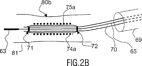
図2A乃至図2Cを参照するに、以下説明する適用では、ステント留置は、通常は狭窄と称される病変の位置において動脈を広げる幾つかの段階を有する医療インターベンションである。予備段階では、術者は患者の動脈81中の狭窄80aの位置を医用画像中で可能な限りよい位置となるようにみつける。次に、医療インターベンションは以下の段階を含む。
With reference to FIGS. 2A-2C, in the application described below, stent placement is a medical intervention having several stages of expanding an artery at the location of a lesion, commonly referred to as a stenosis. In the preliminary stage, the operator finds the position of the
(A)図2Bを参照するに、カテーテル69及び細いガイドワイヤ65を用いて、端部にバルーン74aが巻き付けられ、バルーン74aにステント75aが巻き付けられたモノレール70が導入され、バルーンをステントと共に、バルーンマーカ71、72を用いて動脈81のルーメン80b中の狭窄の位置に位置決めする。
(A) Referring to FIG. 2B, using a
(B)図2Cを参照するに、ステント75aを形成するコイルを広げるために膨張されたバルーン74aとなるようにバルーン74bを膨張させ、ステント75aは動脈壁中に埋め込まれた広げられたステント75bとなる。次に、広げられたステント75bを永久的な埋込物と考え、バルーン75b、モノレール70、ガイドワイヤ65及びカテーテルを除去する。
(B) Referring to FIG. 2C, the
これらのステップ(A)及び(B)の前に、狭窄のある領域で動脈を予め広げる2つの段階が先行してもよい。 Prior to these steps (A) and (B), two stages of pre-expanding the artery in the area with stenosis may precede.
(a)図2Aを参照するに、カテーテル69を用いて、カテーテル69の端部を越えて延び、狭窄の位置において動脈の小さいルーメン80aを通過する細いガイドワイヤ65を導入する。ガイドワイヤ65によって案内され、端部にステントのない第1のバルーン64が巻き付けられた第1のモノレール60を導入する。バルーンマーカ64を用いて、狭窄80aの位置において第1のバルーン64を位置決めする。
(A) Referring to FIG. 2A, a
(b)図2A及び図2Bを参照するに、狭窄の位置における動脈81の狭いルーメン80aを、動脈の広げられた部分80bとなるように広げるために、この第1のバルーン64を膨張させる。次に、第1のバルーン64を第1のモノレール60と共に除去する。
(B) Referring to FIGS. 2A and 2B, the
血管形成法と称される医療インターベンションは、ステントと動脈壁がノイズの多い背景上ではほとんど区別することができず、更に動きを受ける、コントラストの悪い医用画像により、実行が困難である。本発明によれば、ビューイングシステムは、インターベンション中に画像のシーケンスを取得し、インターベンション中にリアルタイムで画像を自動的に処理し表示する手段を有する。このシステムは、通常は画像の参照に対して動いているが必ずしも動いている必要はない関心対象を抽出し位置を見つけるために元の画像に対して適用される第1の手段を有し、背景は参照及び対象のいずれに対しても動いている。対象はほとんど放射線を通さないため、望ましくは関連するマーカを位置決定することによって間接的に位置決定される。抽出手段は、まず、マーカを抽出するために適用される。このシステムは更に、空間フィルタリングを実行する少なくとも1つの処理手段を含む。この技術は、対象が前にマーカに対して位置が見つけられているため、関心対象を強調するのに有効である。空間強調手段は、背景の特徴又は他の望まれていない特徴を強調することなく関心対象の鮮鋭な細部の強調を与えるために関心対象に特に適応される。 Medical interventions called angioplasty are difficult to perform due to poorly contrasted medical images that are hardly distinguishable on a noisy background between the stent and the arterial wall and that are subject to motion. According to the invention, the viewing system comprises means for acquiring a sequence of images during an intervention and automatically processing and displaying the images in real time during the intervention. The system has a first means that is applied to the original image to extract and locate an object of interest that is normally moving but not necessarily moving relative to the image reference; The background is moving for both the reference and the object. Since the object is almost impermeable to radiation, it is preferably located indirectly by locating the associated marker. The extracting means is first applied to extract a marker. The system further includes at least one processing means for performing spatial filtering. This technique is effective for highlighting the object of interest because the object has previously been located relative to the marker. Spatial enhancement means are specifically adapted to the object of interest to provide sharp detail enhancement of the object of interest without enhancing background features or other unwanted features.
心臓学上の適用についての本例では、ユーザは、医療インターベンションを行う者であり、例えば1つ又は複数のツールを動かさない間に、画像処理段階中に介在する可能性を有する。まず、ユーザは、画像中の関心領域を選択しうる。加えて、ユーザは、画像処理手段を作動させ制御するために、図4に示す制御手段58を自由に用いることができる。これらの制御手段は、ユーザが処理動作を開始させるため、処理動作の持続時間を制御するため、及び処理動作を終わらせるための開始手段及び停止手段を有する。特に、ユーザは、最終的な処理された画像が、対象の動きが診断上重要であるか否かに依存して、位置合わせされるか否かを選択しうる。 In this example for cardiological applications, the user is the person performing the medical intervention and has the potential to intervene during the image processing phase, for example while not moving one or more tools. First, the user can select a region of interest in the image. In addition, the user can freely use the control means 58 shown in FIG. 4 to operate and control the image processing means. These control means have a start means and a stop means for the user to start the processing operation, to control the duration of the processing operation, and to end the processing operation. In particular, the user can select whether the final processed image is aligned depending on whether the motion of the object is diagnostically important.
関心対象は、バルーンマーカ61、62又は71、72といった特定の特徴を位置決定することによって間接的に位置決定されることが望ましい。モノレール60上にバルーン64に対して所定の位置に配置されたバルーンマーカ61、62は、動脈のルーメン中でバルーンを拡張させる前に狭窄領域に対する第1のバルーンの位置を決定することを可能とする。モノレール70上にバルーン74aに対して所定の位置で配置され、バルーンマーカ71、72は、ステント拡張前に第2のバルーンの周りに巻き付けられたステント75aの位置を決定し、拡張されたステント75bを最終的に調べることを可能とする。
The object of interest is preferably located indirectly by locating certain features such as
図1A及び図1Cを参照するに、マーカと称されるこれらの特定の特徴は、ステント又は血管壁よりもはるかによいコントラストを示す。抽出手段1は、マーカを元の画像I0から正確に抽出するのに適している。これらのマーカは特定の容易に認識可能な形状を有し、画像中で高いコントラストを有する材料から形成される。従って、これらは抽出が容易である。尚、これらの特定の特徴は、術者にとって実際に最終的に関心となる対象であるコントラストの悪いバルーン、ステント又は血管壁に関するものではない。バルーンマーカ61、62、又は71、72は、モノレール60又は70に関するものであるため、血管壁81又はステント75aのいずれにも関するものではない。バルーンマーカは、バルーンに対して特定の位置を有するため、システム抽出手段1はバルーン64,74a,74bの位置を正確に導出することを可能とする。また、ステント75a、75bは、バルーンマーカに取り付けられてはいないがバルーンマーカに対して特定の位置を有するため、正確に位置決定されうる。
Referring to FIGS. 1A and 1C, these particular features, called markers, exhibit much better contrast than stents or vessel walls. Extraction means 1 is suitable for accurately extracting the marker from the original image I 0. These markers have a specific easily recognizable shape and are formed from a material that has high contrast in the image. Therefore, these are easy to extract. It should be noted that these particular features are not related to poorly contrasting balloons, stents or vessel walls, which are actually the final objects of interest to the operator. Since the
マーカ抽出のための抽出手段1は、同じ関心対象に関連する少なくとも2つのマーカが抽出されるべきであるとき、はるかに効率がよい。このことは、バルーン及びその周りに巻き付けられるステントを支持するモノレールは、バルーンの各端部に配置された2つのマーカを具備するため、特に興味深いものである。バルーンマーカは、実際には蛍光透視画像中の黒い又は少なくとも暗い領域である点の(punctual)ゾーンを構成するため、特に認識可能である。これらはまた、非常に形状が似ている。抽出手段は、各測定(measure)がマーカ又は一対のマーカの所与の特性を表わす一連の基本測定を操作する手段と、同定及び抽出の決定を与えるためのデシジョン・テーブルの規準(criterion)を構築するために基本測定を更に組み合わせる手段を有する。 The extraction means 1 for marker extraction is much more efficient when at least two markers related to the same object of interest are to be extracted. This is particularly interesting because the monorail that supports the balloon and the stent wrapped around it has two markers located at each end of the balloon. Balloon markers are particularly recognizable because they constitute punctual zones that are actually black or at least dark areas in fluoroscopic images. They are also very similar in shape. The extraction means includes means for manipulating a series of basic measurements where each measure represents a given property of a marker or a pair of markers, and a decision table criterion for providing identification and extraction decisions. It has means to further combine the basic measurements to build.
心臓学の分野では、マーカは冠動脈内にある。X線画像は、冠動脈に対して平行に十分に容易に形成されうる2D投影である。従って、マーカ間の距離は、画像のシーケンスに亘って約20%の最大変化を有して略一定のままである。実施の前のマーカ間の実際の距離は、製造者の印から正確にわかる。従って、実際の距離及び最大変化を知っていれば、インターベンション中のマーカ間の距離IMが推定されうる。ビューイングシステムは、この推定された距離IMを画素の数へ変換する手段を有する。 In the field of cardiology, the marker is in the coronary artery. An x-ray image is a 2D projection that can be easily formed sufficiently parallel to the coronary artery. Thus, the distance between the markers remains approximately constant with a maximum change of about 20% over the sequence of images. The actual distance between the markers prior to the implementation is accurately known from the manufacturer's mark. Therefore, if the actual distance and the maximum change are known, the distance IM between the markers during the intervention can be estimated. The viewing system has means for converting this estimated distance IM into a number of pixels.
図1Aを参照するに、抽出手段1はまず、マーカ対の候補を決定するためにマーカの候補を抽出することを可能とするよう実行される基本測定10を有する。抽出手段1は更に、最善のマーカ対を抽出する対抽出手段20を更に有する。
Referring to FIG. 1A, the extraction means 1 first has a
図1Bを参照するに、マーカ抽出手段10では、マーカの候補を特徴付ける基本測定手段は以下のものを有する。 Referring to FIG. 1B, in the marker extraction means 10, basic measurement means for characterizing marker candidates includes the following.
第1の測定手段11は、より明るい背景に対してコントラストを与える点の暗いゾーンを選択するものである。この測定は、F0で示されるフィルタ手段によって与えられる。望ましい例では、図1Cを参照するに、適切なフィルタは、中央ゾーンCZ、デッドゾーンDZ、及び周辺ゾーンPZを含む3つの円形の同心ゾーンを有する。F0は、360°に亘り1乃至nの番号が付されたn個の扇形ゾーンSZへ更に分割される。現在の扇形ゾーンZkは、kで番号が付され、1≦k≦nである。第1の測定は、点の暗いゾーンを探すためにn画像のシーケンスの現在画像をスキャンすることを含む。点の暗いゾーンは、点の暗いゾーンがフィルタの中心に合わされたときに検出されうる。点の暗いゾーンは、中心が合わされると、フィルタの中心ゾーンCZを占め、おそらくはデッドゾーンDZの部分も占める。第1の測定は、中央ゾーンCZと周辺ゾーンPZの間の強度のコントラストの推定値に基づく。このコントラストの推定値は、中央ゾーンCZと周辺ゾーンPZとの間の強度の平均の差を推定することによって行われうる。この簡単な測定は、コントラストの線形推定へと導くこととなる。この推定の結果をより改善するため、第1の測定は、実際にはn個の周辺扇形ゾーンにおいて別々に決定された強度のn平均の最小を計算することによって行われる。これらの強度の最小は、
IPk=kの番号が付された周辺扇形ゾーン中の強度の平均、及び、
ICZ=中央ゾーンCZ中の強度の平均
と示される。
The first measuring means 11 selects a dark zone that gives contrast to a brighter background. This measurement is given by the filter means denoted F 0 . In a preferred example, referring to FIG. 1C, a suitable filter has three circular concentric zones including a central zone CZ, a dead zone DZ, and a peripheral zone PZ. F 0 is further divided into n sector zones SZ numbered 1 to n over 360 °. The current sector zone Z k is numbered k and 1 ≦ k ≦ n. The first measurement involves scanning the current image of a sequence of n images to look for a dark zone of points. A dark spot zone can be detected when the dark spot zone is centered on the filter. A dark spot zone, when centered, will occupy the central zone CZ of the filter, and possibly also part of the dead zone DZ. The first measurement is based on an estimate of the intensity contrast between the central zone CZ and the peripheral zone PZ. This estimate of contrast can be done by estimating the average difference in intensity between the central zone CZ and the peripheral zone PZ. This simple measurement leads to a linear estimation of contrast. In order to further improve the result of this estimation, the first measurement is actually performed by calculating the minimum of the n-means of the intensities determined separately in the n peripheral sector zones. The minimum of these strengths is
The average of the intensity in the peripheral sector zone numbered I Pk = k, and
I CZ = shown as the average intensity in the central zone CZ.
フィルタF0によって与えられる最終的な測定値は、 The final measurement given by filter F 0 is
第2の測定手段12は、Hで示されるヒストグラム手段である。この画像IZ1中、各画素はグレーレベルを有する。画像IZ1から、各グレーレベル値Gに対応する異なる数Hの画素を表わすヒストグラムが形成される。図1Bの軸G上、右に向かって高いグレーレベル値となり、軸G上の左に向かって低いグレーレベル値となる。各グレーレベル値Gに対して、ボックスの高さHは当該のグレーレベル値を有することが見いだされた画素の数を表わす。点の暗いゾーンZの平均的な大きさはフィルタF0の特徴によって決定されるため、画素中の点のゾーンの大きさを推定することが可能である。点のゾーンのサイズがp画素であると想定し、例えば画像IZ1の中にz個のゾーンが見いだされるとすると、最も高いグレーレベルを有するp.z(p×z)個の画素が探される。図1Bに示されるようなヒストグラムHは、軸Gの右から始めて、最も高いグレー値を有するp.z画素、即ちG軸の右にあるボックス中の画素、を選択しつつ、画像について推定された数p.z画素、即ち各p画素のz個のゾーン、に達するまで、隣接するボックス中の画素の数を累積することを可能とする。ヒストグラムHは、p.z画素を生じさせるグレーレベルGHを決定することを可能とする。 The second measuring means 12 is a histogram means indicated by H. In the image IZ1, each pixel has a gray level. A histogram representing a different number H of pixels corresponding to each gray level value G is formed from the image IZ1. The gray level value increases toward the right on the axis G in FIG. 1B and decreases toward the left on the axis G. For each gray level value G, the box height H represents the number of pixels found to have that gray level value. Since the average size of the point dark zone Z is determined by the characteristics of the filter F 0 , it is possible to estimate the size of the point zone in the pixel. Assuming that the size of the zone of points is p pixels, for example, if z zones are found in the image IZ1, p. z (p × z) pixels are sought. Histogram H, as shown in FIG. 1B, starts at the right of axis G and has the highest gray value. Estimating the number of pixels p.p. Allows the number of pixels in adjacent boxes to be accumulated until z pixels, ie z zones of each p pixel, are reached. Histogram H is the p. It is possible to determine the gray level GH that gives rise to z pixels.
第3の測定手段13は、T1によって示される閾値手段である。第1の強度閾値T1が画像IZ1に印加される。閾値T1は、以前に決定されたグレーレベルGHに等しいよう選択される。これは、画像IZ1の中で、少なくともGHに等しいグレーレベルを有するp.z個の画素を選択することを可能とする。画素の強度及び座標がわかっている新しい画像が形成され、点の画像IZ2を形成する。 The third measuring means 13 is a threshold means indicated by T 1 . A first intensity threshold T 1 is applied to the image IZ1. The threshold T 1 is selected to be equal to the previously determined gray level GH . This is the case in the image IZ1 that has a gray level at least equal to GH . It is possible to select z pixels. A new image with known pixel intensity and coordinates is formed, forming a point image IZ2.
第4の測定手段14は、ラベル手段と称され、同じ点の暗いゾーンZに関する画素を接続するために画像IZ2に対して以前に選択された画素に対して連結性(connexity)解析を行うものである。ラベル付け手段14は、新しい画像IZ3中に多数のラベル付けされた点の暗いゾーンを与える。 The fourth measuring means 14 is called label means and performs a connectivity analysis on the previously selected pixels for the image IZ2 in order to connect the pixels relating to the dark zone Z at the same point. It is. The labeling means 14 gives a dark zone of a number of labeled points in the new image IZ3.
第5の測定手段15は、第2の閾値手段T2である。この第2のT2は、例えば、ラベル付けされたゾーンの画像IZ3の画素の強度に対して、また、最善のラベル付けされたゾーンを選択するためにゾーンの直径に対して適用される。例えば、T2は、最も高い強度を有する多数の残る点のゾーン及び構成するマーカについての最善の形状を選択するため、所与の強度と所与の直径の積であり、マーカの像IZ4を生じさせる。 Fifth measuring means 15 is a second threshold value unit T 2. This second T 2 is applied, for example, to the intensity of the pixels of the labeled zone image IZ3 and to the diameter of the zone to select the best labeled zone. For example, T 2 is the product of a given intensity and a given diameter to select the best remaining shape for the number of remaining point zones and the constituent markers with the highest intensity, and the marker image IZ4 Cause it to occur.
第5の測定手段16は、CTで示されるテーブルである。選択された点の暗い領域の可能な対C1,C2のテーブルCTは、マーカ間の事前にわかっている距離IMに基づいて構築され、不確実性は例えば20%である。テーブルCTは、可能なマーカ対C1,C2の画像ICを与える。 The fifth measuring means 16 is a table indicated by CT. A table CT of possible pairs C1, C2 of the dark area of the selected point is constructed based on the a priori known distance IM between the markers, the uncertainty being for example 20%. The table CT gives an image IC of possible marker pairs C1, C2.
図1Aを参照し、可能なマーカ対の画像ICに基づいて、抽出手段1は更に、以下の規準に基づいて最善のマーカ対を抽出する対抽出手段20を有する。 Referring to FIG. 1A, based on the image IC of possible marker pairs, the extraction means 1 further includes a pair extraction means 20 that extracts the best marker pair based on the following criteria.
距離の規準。最善の対のマーカ間の距離は、所与の不確実性を伴って、事前に分かっている距離IMに非常に近くなくてはならない。 Distance criteria. The distance between the best pair of markers must be very close to the previously known distance IM with a given uncertainty.
強さの規準。最善の対の強さは、他の対の強さよりも大きくなくてはならない。所与の対の強さは、フィルタF0によって生ずる強調された強度の平均として決定されうる。 Strength criteria. The best pair strength must be greater than the other pair strengths. The strength of a given pair may be determined as an average of the enhanced intensity caused by the filter F 0.
類似性の規準。最善の対のマーカは、非常に類似した構造でなくてはならない。可能な対のマーカの類似性が決定される。p画素の点の暗いゾーンZが決定されると、それらの重心が計算される。図3B中に白い四角形で示されるように、各重心の周りに、ROIとして示される小さい関心領域が画成される。各可能な対に値して、対応するROIの間の相関が計算される。強い相関は、2つの強い相関を示すROIがマーカ対のマーカに対応することを示す。 Similarity criteria. The best pair of markers must have a very similar structure. Possible pair marker similarity is determined. Once dark zones Z of p-pixel points are determined, their centroids are calculated. A small region of interest, shown as ROI, is defined around each centroid, as shown by the white squares in FIG. 3B. For each possible pair, the correlation between the corresponding ROIs is calculated. A strong correlation indicates that two strong correlation ROIs correspond to the markers of the marker pair.
連続的な軌跡の規準。対のマーカは、ガイドワイヤによって案内されるモノレールによって担持される。ガイドワイヤは、多少は可視である。しかしながら、これはリッジフィルタによって検出されうる。従って、可能な対のマーカがそれらをつなぐリッジに対応する軌跡上に位置する場合は、これは、連続的な軌跡の端部に位置する2つのゾーンが一対のマーカに対応することの他の指標となる。このような連続的な軌跡は、2つのゾーンをつなぐ経路に沿って平均的なリッジ性を推定することによって認定さえうる。平均的なリッジ性の測定は、セグメントの形又は出来るだけ双曲線に近い形を有する軌跡を与えねばならない。連続的な軌跡の評価は、交互に、高速マーチング技術を用いて行われうる。 Continuous trajectory criteria. The pair of markers is carried by a monorail guided by a guide wire. The guide wire is somewhat visible. However, this can be detected by a ridge filter. Thus, if a possible pair of markers are located on the trajectory corresponding to the ridge connecting them, this is another case where the two zones located at the end of the continuous trajectory correspond to the pair of markers. It becomes an indicator. Such a continuous trajectory can even be identified by estimating the average ridgeness along the path connecting the two zones. The average ridge measurement should give a trajectory having a segment shape or a shape that is as close to a hyperbola as possible. Continuous trajectory evaluation can alternatively be performed using high-speed marching techniques.
動きの規準。冠動脈の中にあるマーカは、心拍に対して高速に動いている。誤ったアラーム、即ち、背景に関連する暗い点のゾーンは、患者の呼吸とともにもっとゆっくりと動いている。これらの可能な誤ったアラームを排除するために、シーケンスの2つの連続する画像間で時間的な差が行われる。この差は、時間的なコントラストの測定を与える。時間的なコントラストの測定は、重要な時間的なコントラストを示す暗い点のゾーンを検出することを可能とする。この測定はまた、誤ったアラームはより弱い時間的なコントラストを有するため、可能なマーカ対の標識である。上述の全ての規準は、複合的な測定値を導出するためにファジー論理技術を用いて組み合わされる。複合的な測定値が高ければ高いほど、一対のマーカの存在の確率は高くなる。最も高い複合測定値は、マーカ抽出手段1から生じた対の画像ICから最善のマーカ対を選択することを可能とする。このマーカの座標が決定される。元の画像I0の強度と最善の対のマーカの座標とを含む、結果して得られた情報は、IF1と示され、空間フィルタリング手段を有する強調手段2における更なる処理に用いられる。 Standard of movement. The marker in the coronary artery moves at high speed with respect to the heartbeat. The false alarm, ie the dark spot zone associated with the background, moves more slowly with the patient's breathing. In order to eliminate these possible false alarms, a time difference is made between two consecutive images of the sequence. This difference gives a measure of temporal contrast. Temporal contrast measurements make it possible to detect zones of dark spots that exhibit significant temporal contrast. This measurement is also a marker of possible marker pairs because false alarms have a weaker temporal contrast. All of the above criteria are combined using fuzzy logic techniques to derive composite measurements. The higher the combined measurement value, the higher the probability of the presence of a pair of markers. The highest composite measurement value makes it possible to select the best marker pair from the paired image IC generated from the marker extraction means 1. The coordinates of this marker are determined. The resulting information, including the intensity of the original image I 0 and the coordinates of the best pair of markers, is denoted I F1 and is used for further processing in the enhancement means 2 with spatial filtering means.
図1Aを参照するに、空間フィルタリング手段2は、マーカ座標情報を伴う元の画像の強度IF1に適用される。空間フィルタリング手段2は、背景の特徴を除去すると同時に、狭窄のある動脈の壁といった関心対象の境界及び/又はステントの境界を強調することを目的とする。これらの関心対象は、既に検出されているバルーンマーカの間に略配置される。上述のように、バルーンマーカの間の実際の距離は、ステントの参照に従ってステント製造者によって与えられる製造者から、センチメートル又は画素単位で近似されうる。医師は、ステント径について知っており、これはやはりステント製造者によって与えられ、バルーンマーカ間の近似された距離の分数として推定されうる狭窄のある動脈の径の仮定をもっている。図3Bを参照するに、以前にマーカが検出されている元の画像のなかで関心領域が定義されている。図3B中、この領域は破線によって境界が引かれている。セグメントIMは、図1Dに示すように2つのマーカをつなぐ。動脈壁又はステントの境界は、例えばX線画像中の明るい背景上の濃い線で表わされるリッジ構造である。図1Aを参照するに、これらのリッジ構造は、Rで示されるリッジフィルタ31といった従来のリッジ強調手段を用いて強調される。しかしながら、従来のリッジフィルタRはまた、関心対象に加えて背景の多数の寄生特徴を強調する。このような寄生特徴を排除するため、本発明によれば、従来のフィルタRは多数の重み係数で調節される。従って、候補点Qはまず従来のリッジフィルタRで検出され、次に、点Qの強度は以下に説明する幾つかの重み係数を受ける。
Referring to FIG. 1A, the spatial filtering means 2 is applied to the intensity I F1 of the original image with marker coordinate information. The spatial filtering means 2 aims to remove background features and at the same time enhance the boundary of interest and / or the stent boundary, such as the wall of a stenotic artery. These objects of interest are generally placed between already detected balloon markers. As mentioned above, the actual distance between balloon markers can be approximated in centimeters or pixels from the manufacturer given by the stent manufacturer according to the stent reference. The physician knows about the stent diameter, which is also given by the stent manufacturer and has an assumption of the diameter of the artery with the stenosis that can be estimated as a fraction of the approximate distance between the balloon markers. Referring to FIG. 3B, the region of interest is defined in the original image from which the marker has been previously detected. In FIG. 3B, this area is bordered by a broken line. Segment IM connects two markers as shown in FIG. 1D. The boundary of the artery wall or stent is a ridge structure represented by a dark line on a light background in the X-ray image, for example. Referring to FIG. 1A, these ridge structures are enhanced using conventional ridge enhancement means such as a
第1の重み係数αDは、強調されるべき候補と見なされる検出されたリッジ構造AB上に位置するリッジ点Qから、マーカをつなぐ以前に定義されたセグメントIMへの距離に基づくものである。図1Dに示すように、この距離は、D(Q,IM)によって示される。図1Aの32で示す重み関すf(D)は、値D(Q,IM)がステント半径又は動脈の半径の値に略等しいときにこの関数の値が1に近づき、値D(Q,IM)がステント又は動脈の半径の値から遠ざかれば遠ざかるほどこの関数の値が小さくなるよう定義される。従って、第1の重み係数は、
αD=f[D(Q,IM)]
で与えられる。この重み係数は、セグメントIMの周りの点を有利に扱い、背景の点を不利に扱うことを可能とする。
The first weighting factor α D is based on the distance from the ridge point Q located on the detected ridge structure AB considered as a candidate to be emphasized to the previously defined segment IM connecting the markers. . As shown in FIG. 1D, this distance is denoted by D (Q, IM). 1 (A), the value of this function approaches 1 when the value D (Q, IM) is approximately equal to the value of the stent radius or artery radius, and the value D (Q, IM) ) Is defined as the value of this function decreases with increasing distance from the radius value of the stent or artery. Therefore, the first weighting factor is
α D = f [D (Q, IM)]
Given in. This weighting factor allows the points around the segment IM to be handled advantageously and the background points to be handled disadvantageously.
第2の重み係数αθは、強調されるべき候補である検出されたリッジABの方向に基づく。従来のリッジフィルタRは、候補リッジ構造の方向を与える傾向がある。図1Dに示すように、セグメントIMの中心Oを通る、候補リッジ構造ABの平行線A’B’と、以前に定義されたセグメントIMとの間の角度が測定される。この角度はΔ(θQ,θIM)で示される。図1A中、参照番号33で示される重み関数g(Δθ)は、角度値Δ(θQ,θIM)が略ゼロであるときこの関数の値が1に近づき、角度値Δ(θQ,θIM)が値π/2に向かって増えるにつれてこの関数の値が増えるよう定義される。従って、第2の重み係数は、
αθ=g[Δ(θQ,θIM)]
で与えられる。この重み係数は、セグメントIMに平行なリッジ構造上に位置する点を有利に扱い、背景の点を不利に扱うことを可能とする。
The second weighting factor α θ is based on the direction of the detected ridge AB that is a candidate to be enhanced. The conventional ridge filter R tends to give the direction of the candidate ridge structure. As shown in FIG. 1D, the angle between the parallel line A′B ′ of the candidate ridge structure AB through the center O of the segment IM and the previously defined segment IM is measured. This angle is indicated by Δ (θ Q , θ IM ). In FIG. 1A, the weighting function g (Δθ) indicated by
α θ = g [Δ (θ Q , θ IM )]
Given in. This weighting factor makes it possible to handle points located on the ridge structure parallel to the segment IM and to treat background points disadvantageously.
第3の重み係数αCは、図1A中に参照番号34で示されるように、単に定数Cから定義される。他の重み係数は、抽出されるべき構造の強度、形状、他の特徴に従って定義されうる。
The third weighting factor α C is simply defined from a constant C, as indicated by
これらの重み係数を定義すると、強調手段2は、これらの係数を、従来のリッジフィルタRによってフィルタリングされた現在画素の強度IRに適用し、
αCαθαDIR
の形の重み付けされた係数を生じさせる乗算手段41を有する。次に、強調手段2は、式に従って、元の画像I0を強調するために重み付け強度を用い、ここで、IRは従来のリッジフィルタRによってフィルタリングされた現在画素の強度であり、42はI0と重み付けされた強度αCαθαDIRとの間の差を与える差分手段であり、IF2は、
IF2=I0−αCαθαDIR
となるような、本発明による空間強調手段2の出口における現在画素の強度である。当業者によれば、強調されるべき関心対象及び除去すべき特徴に対して、他の式が使用されうる。
Once these weighting factors are defined, the enhancement means 2 applies these coefficients to the current pixel intensity I R filtered by the conventional ridge filter R;
α C α θ α D I R
Multiplication means 41 for producing weighted coefficients of the form The enhancement means 2 then uses the weighted intensity to enhance the original image I 0 according to the equation, where I R is the intensity of the current pixel filtered by the conventional ridge filter R and 42 is I F2 is a difference means that gives the difference between I 0 and the weighted intensity α C α θ α D I R ,
I F2 = I 0 −α C α θ α D I R
Is the intensity of the current pixel at the exit of the space enhancement means 2 according to the invention. According to those skilled in the art, other formulas can be used for the object of interest to be emphasized and the features to be removed.
本発明によれば、上述の形の式で定義されるような空間強調手段2は、心臓学での適用において、又は、関心対象内に似た構造が見つけられるべき任意の適用において、強調されるべき特定の構造に安全に適応される新しいリッジフィルタ手段F2を構成する。この新しいリッジフィルタは、セグメントIMの周りの点を強調し、同時に、背景の点及び背景のリッジ特徴を除去する。血管形成法への適用では、この完全に適応されたリッジフィルタF2は、例えば、バルーンの膨張の後に動脈のルーメンの正しい広がりを調べることを可能とし、又は、正しいステントの広がりを調べることを可能とする。 According to the present invention, the space enhancement means 2 as defined by the above formula is emphasized in cardiology applications or in any application where a similar structure within an object of interest is to be found. It constitutes a new ridge filter means F 2 that is safely adapted to the particular structure to be. This new ridge filter enhances the points around the segment IM and at the same time removes the background points and the background ridge features. In an angioplasty application, this fully adapted ridge filter F 2 makes it possible to examine the correct spread of the arterial lumen after balloon inflation, for example, or to examine the correct stent spread. Make it possible.
図3Aは、カテーテル、ガイドワイヤ、バルーンマーカ(2つの小さい暗い点)を有するバルーン、及び、他の器官の背景上の動脈を表わす医用シーケンスの元の画像を示す。関心対象(バルーン及び動脈)の視覚化は非常に困難である。バルーンマーカでさえも殆ど可視でない。図4Bは、点の暗いゾーンの決定のために白で境界が付けられたゾーンを有する元の画像を示す。破線は、候補リッジを強調するための関心領域の枠を表わす。図3C中、画像は、本発明に従って処理されており、従って、関心対象は強調され背景はフィルタリングされる。 FIG. 3A shows an original image of a medical sequence representing an artery on the background of a catheter, guide wire, balloon with balloon markers (two small dark spots), and other organs. Visualization of objects of interest (balloons and arteries) is very difficult. Even balloon markers are hardly visible. FIG. 4B shows the original image with zones bordered in white for the determination of the dark zone of points. The broken line represents a frame of the region of interest for emphasizing the candidate ridge. In FIG. 3C, the image has been processed according to the present invention, so that the object of interest is enhanced and the background is filtered.
インターベンション中の医師の使い心地のため、マーカは、現在画像の対応するマーカと画像のシーケンス中の参照画像の対応するマーカとを一致させることにより、画像のフレームに対して時間的に位置合わせされうる。マーカ位置合わせは、マーカに対して実質的に動かない関心対象の更なる位置合わせを可能とする。従って、図3Cに示すように、関心対象は、移動して画像の枠から出ることなくズームされうる。また、時間的なフィルタリング手段は、シーケンスの画像を更に改善するために本発明の手段と共に使用されうる。 For the convenience of the physician during the intervention, the marker is temporally aligned with the frame of the image by matching the corresponding marker of the current image with the corresponding marker of the reference image in the sequence of images. Can be done. Marker alignment allows further alignment of the object of interest that does not move substantially relative to the marker. Thus, as shown in FIG. 3C, the object of interest can be zoomed without moving out of the frame of the image. Temporal filtering means can also be used with the means of the present invention to further improve the image of the sequence.
本発明はまた、体の器官の中で器具を動かすこと及び/位置決めすることを含む医療インターベンションをリアルタイムで視覚化するために上述のようにシステムにおいて使用されるべきコンピュータ実行可能な画像処理方法に関連し、この方法は、画像のシーケンスを取得する段階と、これらの画像を処理する段階と、ユーザが器官の中の所定の位置に器具を位置決めし、医療インターベンションの段階がうまく実行されたかを調べるために画像を表示する段階とを有する。この方法は、関心対象の位置を導出するためにマーカ位置を決定する段階を含む。この方法は、本発明の適応リッジフィルタを用いて背景の特徴を除去する一方で関心対象を強調する更なる段階を有する。 The present invention also provides a computer-executable image processing method to be used in a system as described above for visualizing medical intervention in real time including moving and / or positioning an instrument within a body organ. In this method, the steps of obtaining a sequence of images, processing these images, and the user positioning the instrument at a predetermined location in the organ and performing the medical intervention step are performed successfully. Displaying an image for checking whether or not. The method includes determining a marker position to derive a position of interest. The method has the further step of enhancing the object of interest while removing background features using the adaptive ridge filter of the present invention.
図4は、医療検査装置50を示す図である。装置は、画像のシーケンスのディジタル画像データを取得する手段51を有し、上述の処理方法に従ってこれらのデータを処理するために上述のように医療ビューイングシステム42に結合される。医療ビューイングシステムは、一般的には、リアルタイム画像を処理するために手術室又は手術室の近くで用いられる。本発明の方法の段階が、例えば医療パラメータを推定するために、記憶された医療画像に適用されるとき、記憶された画像のデータを処理するシステムは、医療ビューイングステーションと称される。医療検査装置は、システム53への接続57により画像データを与える。システムは、処理された画像データを、ディスプレイ及び/又は記憶手段へ与える。ディスプレイ手段54は、画面でありうる。記憶手段は、システム53のメモリMEMでありうる。この記憶手段は、或いは外部記憶手段であってもよい。この画像ビューイングシステム53は、適切にプログラムされたコンピュータ、又は、本発明による方法の段階の機能を実行するようにされたLUT、メモリ、フィルタ、論理オペレータ等の回路手段を有する専用プロセッサを含みうる。システム53はまた、キーボード55及びマウス56を含みうる。ユーザが、選択された段階においてシステムの処理手段を開始し、持続時間を制御し、停止させるための制御手段58を構成するよう、マウスのクリックによって作動されるべきアイコンが画面上に与えられてもよく、又は、システム上に特別なプッシュボタンが設けられてもよい。
FIG. 4 is a diagram showing the
Claims (12)
前記画像のシーケンスを取得する取得手段と、前記画像を処理する処理手段とを含み、
前記処理手段は、
点の暗いゾーンを、マーカを形成する候補としてフィルタリングし強調し、かつ前記関心対象に関連する最善の推定値を与える前記マーカ対を形成する前記マーカを決定する規準に基づいて決定を行う、マーカ抽出手段であって、前記決定する規準は、前記マーカの距離、前記マーカ対のマーカのコントラストの強さ、前記マーカ対の中のマーカの類似性、前記マーカ間の軌跡の連続性、前記背景中の特徴の動きとは実質的に異なる前記マーカの動きの類似性に関する幾つかの規準の組合せであるところのマーカ抽出手段と、
前記背景の稜線特徴は強調されず、一方で、推定された前記マーカ対によって特徴付けられた前記関心対象の稜線特徴は強調される、処理された画像を計算する空間フィルタリング手段と、
前記フィルタリングされた背景上に前記強調された関心対象の処理された画像を表示する表示手段とを有し、
前記空間フィルタリング手段は、
前記画像中の稜線を抽出するリッジフィルタリング手段と、
前記関心対象に特有な稜線特徴を強調し、前記背景に特有な稜線特徴を排除するよう前記リッジフィルタリング手段を調節する調節手段とを有し、
前記調節手段は、
前記関心対象に特有な稜線特徴を有利に扱い、前記背景に特有な稜線特徴を不利に扱う重み係数手段と、
前記リッジフィルタリング手段に前記調節手段を適用する組合せ手段とを有し、
前記リッジフィルタリング手段を調節する前記重み係数手段は、
候補稜線の点からマーカ対のマーカをつなぐセグメントへの距離に基づき、前記セグメントの周りに配置された点を有利に扱う重み係数手段と、
前記マーカ対をつなぐセグメントと候補稜線の角度に基づいて、前記マーカ対をつなぐセグメントに平行な稜線を有利に扱う重み係数手段とを有し、
これらの係数は、乗算手段によって、前記リッジフィルタ強度を調節するリッジフィルタから生ずる強度に掛け合わされる、ビューイングシステム。A viewing system that emphasizes an object of interest represented in a background in a sequence of images with noise, displays the sequence of enhanced images, and a marker pair is associated with the object of interest;
Including acquisition means for acquiring the sequence of images, and processing means for processing the images,
The processing means includes
A marker that filters and emphasizes dark zones of points as candidates to form a marker and makes a decision based on criteria for determining the marker that forms the marker pair that gives the best estimate associated with the object of interest The criteria for determining are the distance of the marker, the contrast strength of the marker of the marker pair, the similarity of the markers in the marker pair, the continuity of the trajectory between the markers, the background Marker extraction means that is a combination of several criteria relating to similarity of movement of the marker that is substantially different from movement of the features therein;
Spatial filtering means for computing a processed image, wherein the background edge features are not enhanced, while the edge features of interest characterized by the estimated marker pairs are enhanced;
Have a display means for displaying the processed image of enhanced interest on the filtered background,
The spatial filtering means includes
Ridge filtering means for extracting ridge lines in the image;
Adjusting means for adjusting the ridge filtering means so as to emphasize edge features unique to the object of interest and to eliminate edge features unique to the background;
The adjusting means is
A weighting factor means that advantageously treats the edge features unique to the object of interest and disadvantageously treats the edge features unique to the background;
Combining means for applying the adjusting means to the ridge filtering means;
The weight coefficient means for adjusting the ridge filtering means is:
Based on the distance from the point of the candidate ridge to the segment connecting the markers of the marker pair, weighting factor means for advantageously handling the points arranged around the segment;
Weight coefficient means for advantageously handling a ridge line parallel to the segment connecting the marker pair based on the angle of the segment connecting the marker pair and the candidate ridge line;
These coefficients are multiplied by the intensity resulting from the ridge filter which adjusts the ridge filter intensity by means of multiplication .
前記抽出手段は、前記関心対象に関連する特徴と考えられる一対のバルーンマーカを自動的に抽出し、前記バルーンマーカは前記バルーンにも前記動脈にも関連せず、
前記位置合わせ手段は、前記画像中で、前記バルーンマーカと、関連するバルーン、ステント及びステントとを時折位置合わせし、
前記空間フィルタリング手段は、背景特徴をフィルタリングする一方でバルーン、ステント、又は動脈の境界を強調し、
前記表示手段は、ユーザが動脈中でステントのある又はステントなしのバルーンを、バルーンマーカ位置情報を用いて動脈の一部の特定の位置に位置決めするようインターベンション中に画像を表示し、前記インターベンションは、バルーン膨張及びおそらくはステントの展開の段階を有する、システム。Displaying a sequence of medical images of a medical intervention comprising moving and / or positioning a device called a balloon with or without a stent wound within the artery, said balloon, stent and artery Are considered to be of interest and the balloon is carried by a support called a monorail on which two positioning features called balloon markers are attached and arranged corresponding to the ends of the balloon A viewing system according to any one of claims 1 to 6 ,
The extraction means automatically extracts a pair of balloon markers that are considered features related to the object of interest, the balloon markers are not related to the balloon or the artery,
The alignment means occasionally aligns the balloon marker and associated balloon, stent and stent in the image;
The spatial filtering means enhances balloon, stent, or artery boundaries while filtering background features;
The display means displays an image during an intervention so that a user positions a stented or unstented balloon in an artery at a specific position of a part of the artery using balloon marker position information, and Bention is a system that has a stage of balloon inflation and possibly stent deployment.
前記画像のシーケンスを取得する取得ステップと、
点の暗いゾーンを、マーカを形成する候補としてフィルタリングし強調し、かつ前記関心対象に関連する最善の推定値を与える前記マーカ対を形成する前記マーカを決定する規準に基づいて決定を行う、マーカ抽出ステップであって、前記決定する規準は、前記マーカの距離、前記マーカ対のマーカのコントラストの強さ、前記マーカ対の中のマーカの類似性、前記マーカ間の軌跡の連続性、前記背景中の特徴の動きとは実質的に異なる前記マーカの動きの類似性に関する幾つかの規準の組合せであるところのマーカ抽出ステップと、
前記背景の稜線特徴は強調されず、一方で、推定された前記マーカ対によって特徴付けられた前記関心対象の稜線特徴は強調される、処理された画像を計算する空間フィルタリングするステップと、
前記空間フィルタリングするステップは、
前記画像中の稜線を抽出するリッジフィルタリングステップと、
前記関心対象に特有な稜線特徴を強調し、前記背景に特有な稜線特徴を排除するよう前記リッジフィルタリングステップを調節する調節ステップとを有し、
前記調節ステップは、
前記関心対象に特有な稜線特徴を有利に扱い、前記背景に特有な稜線特徴を不利に扱う重み係数ステップと、
前記リッジフィルタリングステップに前記調節ステップを適用するステップとを有し、
前記リッジフィルタリングステップを調節する前記重み係数ステップは、
候補稜線の点からマーカ対のマーカをつなぐセグメントへの距離に基づき、前記セグメントの周りに配置された点を有利に扱う重み係数ステップと、
前記マーカ対をつなぐセグメントと候補稜線の角度に基づいて、前記マーカ対をつなぐセグメントに平行な稜線を有利に扱う重み係数ステップとを有し、
これらの係数は、乗算手段によって、前記リッジフィルタ強度を調節するリッジフィルタから生ずる強度に掛け合わされる、
装置の作動方法。A working how emphasize apparatus represented an interest in the background in a sequence of images with noise, marker pair is associated with the object of interest,
Obtaining a sequence of the images;
A marker that filters and emphasizes dark zones of points as candidates to form a marker and makes a decision based on criteria for determining the marker that forms the marker pair that gives the best estimate associated with the object of interest Extraction step , wherein the criteria to be determined are the marker distance, the strength of the marker contrast of the marker pair, the similarity of the markers in the marker pair, the continuity of the trajectory between the markers, the background A marker extraction step that is a combination of several criteria relating to the similarity of the movement of the marker that is substantially different from the movement of the features therein;
Spatial filtering to calculate a processed image, wherein the background edge features are not enhanced, while the edge features of interest characterized by the estimated marker pairs are enhanced;
The spatial filtering comprises:
A ridge filtering step of extracting a ridge line in the image;
Adjusting the ridge filtering step to emphasize edge features specific to the object of interest and to exclude edge features specific to the background;
The adjusting step includes
A weighting factor step that advantageously treats the edge features unique to the object of interest and disadvantageously treats the edge features unique to the background;
Applying the adjusting step to the ridge filtering step;
The weighting factor step for adjusting the ridge filtering step is:
A weighting factor step that advantageously treats the points placed around the segment based on the distance from the candidate ridge point to the segment connecting the markers of the marker pair;
A weighting factor step that advantageously handles edges parallel to the segments connecting the marker pairs based on the angles of the segments connecting the marker pairs and the candidate edges;
These coefficients are multiplied by the intensity resulting from the ridge filter that adjusts the ridge filter intensity by means of multiplication.
How the device works.
Applications Claiming Priority (2)
| Application Number | Priority Date | Filing Date | Title |
|---|---|---|---|
| EP01403180 | 2001-12-07 | ||
| PCT/IB2002/005081 WO2003049032A2 (en) | 2001-12-07 | 2002-12-02 | Medical viewing system and method for spatially enhancing structures in noisy images |
Publications (3)
| Publication Number | Publication Date |
|---|---|
| JP2005512372A JP2005512372A (en) | 2005-04-28 |
| JP2005512372A5 JP2005512372A5 (en) | 2006-01-26 |
| JP4430937B2 true JP4430937B2 (en) | 2010-03-10 |
Family
ID=8183011
Family Applications (1)
| Application Number | Title | Priority Date | Filing Date |
|---|---|---|---|
| JP2003550151A Expired - Lifetime JP4430937B2 (en) | 2001-12-07 | 2002-12-02 | Medical viewing system and method for spatial enhancement of structures in noisy images |
Country Status (6)
| Country | Link |
|---|---|
| US (1) | US7340108B2 (en) |
| EP (1) | EP1459257B1 (en) |
| JP (1) | JP4430937B2 (en) |
| CN (1) | CN100557632C (en) |
| AU (1) | AU2002351078A1 (en) |
| WO (1) | WO2003049032A2 (en) |
Families Citing this family (37)
| Publication number | Priority date | Publication date | Assignee | Title |
|---|---|---|---|---|
| JP4804005B2 (en) * | 2002-11-13 | 2011-10-26 | コーニンクレッカ フィリップス エレクトロニクス エヌ ヴィ | Medical viewing system and method for detecting boundary structures |
| CN1950031A (en) * | 2004-04-29 | 2007-04-18 | 皇家飞利浦电子股份有限公司 | Viewing system for control of PTCA angiograms |
| DE602005006837D1 (en) | 2004-11-24 | 2008-06-26 | Koninkl Philips Electronics Nv | TIME FILTERING WITH MULTIPLE CHARACTERISTICS FOR STRUCTURAL IMPROVEMENT IN HARMFUL PICTURES |
| WO2007064739A2 (en) | 2005-11-29 | 2007-06-07 | Surgi-Vision, Inc. | Mri-guided localization and/or lead placement systems, related methods, devices and computer program products |
| US20080127006A1 (en) * | 2006-10-27 | 2008-05-29 | International Business Machines Corporation | Real-Time Data Stream Decompressor |
| US8175677B2 (en) * | 2007-06-07 | 2012-05-08 | MRI Interventions, Inc. | MRI-guided medical interventional systems and methods |
| US20100209012A1 (en) * | 2007-09-21 | 2010-08-19 | Koninklijke Philips Electronics N.V. | Method of enhancement of moving structure using double-warping |
| CA2700523A1 (en) | 2007-09-24 | 2009-04-02 | Surgivision, Inc. | Mri-guided medical interventional systems and methods |
| US8315689B2 (en) | 2007-09-24 | 2012-11-20 | MRI Interventions, Inc. | MRI surgical systems for real-time visualizations using MRI image data and predefined data of surgical tools |
| WO2009044321A2 (en) * | 2007-10-01 | 2009-04-09 | Koninklijke Philips Electronics N.V. | Detection and tracking of interventional tools |
| EP2403408B1 (en) | 2009-03-06 | 2017-11-15 | Koninklijke Philips N.V. | Medical viewing system for displaying a region of interest on medical images |
| US9082182B2 (en) * | 2009-11-25 | 2015-07-14 | Dental Imaging Technologies Corporation | Extracting patient motion vectors from marker positions in x-ray images |
| US8363919B2 (en) * | 2009-11-25 | 2013-01-29 | Imaging Sciences International Llc | Marker identification and processing in x-ray images |
| US9082036B2 (en) * | 2009-11-25 | 2015-07-14 | Dental Imaging Technologies Corporation | Method for accurate sub-pixel localization of markers on X-ray images |
| US9082177B2 (en) * | 2009-11-25 | 2015-07-14 | Dental Imaging Technologies Corporation | Method for tracking X-ray markers in serial CT projection images |
| US9826942B2 (en) | 2009-11-25 | 2017-11-28 | Dental Imaging Technologies Corporation | Correcting and reconstructing x-ray images using patient motion vectors extracted from marker positions in x-ray images |
| WO2011117789A1 (en) * | 2010-03-24 | 2011-09-29 | Koninklijke Philips Electronics N.V. | System and method for producing an image of a physical object |
| WO2012046844A1 (en) | 2010-10-08 | 2012-04-12 | 株式会社東芝 | Medical image processing device |
| JP5867306B2 (en) * | 2012-06-20 | 2016-02-24 | 株式会社島津製作所 | X-ray fluoroscopic equipment |
| WO2014053970A1 (en) * | 2012-10-05 | 2014-04-10 | Koninklijke Philips N.V. | Roi painting |
| JP2016019724A (en) | 2014-06-19 | 2016-02-04 | 株式会社東芝 | X-ray diagnostic equipment |
| JP6552831B2 (en) * | 2015-02-03 | 2019-07-31 | キヤノンメディカルシステムズ株式会社 | Image processing apparatus and X-ray diagnostic apparatus |
| US10325380B2 (en) * | 2016-01-12 | 2019-06-18 | University Of Iowa Research Foundation | Precise, low-cost orthopaedic surgical simulator |
| US11504191B2 (en) | 2016-01-19 | 2022-11-22 | Titan Medical Inc. | Graphical user interface for a robotic surgical system |
| US9760978B1 (en) * | 2016-05-09 | 2017-09-12 | Adobe Systems Incorporated | Missing region prediction |
| US9911201B2 (en) | 2016-06-23 | 2018-03-06 | Adobe Systems Incorporated | Imaging process initialization techniques |
| KR101887760B1 (en) * | 2016-10-10 | 2018-08-10 | 순천향대학교 산학협력단 | Breast cancer diagnosis apparatus using thermal camera and method thereof |
| DE102017201162B4 (en) * | 2017-01-25 | 2020-09-17 | Siemens Healthcare Gmbh | Method for operating an X-ray device with an improved display of a medical component |
| US10467786B2 (en) * | 2017-02-28 | 2019-11-05 | General Electric Company | Systems and methods of stent image enhancement |
| US10905497B2 (en) | 2017-04-21 | 2021-02-02 | Clearpoint Neuro, Inc. | Surgical navigation systems |
| US11403966B2 (en) | 2018-04-07 | 2022-08-02 | University Of Iowa Research Foundation | Fracture reduction simulator |
| JP7091919B2 (en) * | 2018-08-02 | 2022-06-28 | 株式会社島津製作所 | Radiation imaging device |
| DE102018222595A1 (en) * | 2018-12-20 | 2020-06-25 | Siemens Healthcare Gmbh | Process for image processing of an image data set of a patient, medical imaging device, computer program and electronically readable data carrier |
| JP7341679B2 (en) * | 2019-03-05 | 2023-09-11 | キヤノンメディカルシステムズ株式会社 | Medical image processing equipment, X-ray diagnostic equipment, and medical image processing programs |
| JP7373980B2 (en) * | 2019-11-29 | 2023-11-06 | キヤノンメディカルシステムズ株式会社 | X-ray diagnostic equipment and marker detection program |
| CN113723406B (en) * | 2021-09-03 | 2023-07-18 | 乐普(北京)医疗器械股份有限公司 | A processing method and device for stent positioning on coronary angiography images |
| CN113689355B (en) * | 2021-09-10 | 2022-07-08 | 数坤(北京)网络科技股份有限公司 | Image processing method, image processing device, storage medium and computer equipment |
Family Cites Families (17)
| Publication number | Priority date | Publication date | Assignee | Title |
|---|---|---|---|---|
| JP4054402B2 (en) * | 1997-04-25 | 2008-02-27 | 株式会社東芝 | X-ray tomography equipment |
| IL70213A (en) * | 1983-11-13 | 1988-02-29 | Paul Fenster | Digital fluorographic image enhancement system |
| DE3442736C2 (en) * | 1984-11-23 | 1987-03-05 | Tassilo Dr.med. 7800 Freiburg Bonzel | Dilatation catheter |
| US5209728B1 (en) * | 1989-11-02 | 1998-04-14 | Danforth Biomedical Inc | Low profile high performance interventional catheters |
| US5490516A (en) * | 1990-12-14 | 1996-02-13 | Hutson; William H. | Method and system to enhance medical signals for real-time analysis and high-resolution display |
| US5343390A (en) * | 1992-02-28 | 1994-08-30 | Arch Development Corporation | Method and system for automated selection of regions of interest and detection of septal lines in digital chest radiographs |
| DE69322444T2 (en) * | 1992-07-10 | 1999-06-24 | Koninklijke Philips Electronics N.V., Eindhoven | X-ray fluoroscopy device with means for noise reduction |
| EP0610916A3 (en) * | 1993-02-09 | 1994-10-12 | Cedars Sinai Medical Center | Method and apparatus for providing preferentially segmented digital images. |
| US5771895A (en) * | 1996-02-12 | 1998-06-30 | Slager; Cornelis J. | Catheter for obtaining three-dimensional reconstruction of a vascular lumen and wall |
| US5784431A (en) * | 1996-10-29 | 1998-07-21 | University Of Pittsburgh Of The Commonwealth System Of Higher Education | Apparatus for matching X-ray images with reference images |
| US5779731A (en) | 1996-12-20 | 1998-07-14 | Cordis Corporation | Balloon catheter having dual markers and method |
| US5982915A (en) * | 1997-07-25 | 1999-11-09 | Arch Development Corporation | Method of detecting interval changes in chest radiographs utilizing temporal subtraction combined with automated initial matching of blurred low resolution images |
| CA2310550A1 (en) | 1999-06-04 | 2000-12-04 | Eclipse Surgical Technologies, Inc. | Enhanced surgical device tracking system |
| US6941323B1 (en) * | 1999-08-09 | 2005-09-06 | Almen Laboratories, Inc. | System and method for image comparison and retrieval by enhancing, defining, and parameterizing objects in images |
| DE60018430T2 (en) | 1999-10-26 | 2006-02-16 | Koninklijke Philips Electronics N.V. | PICTURE PROCESSING METHOD, SYSTEM AND DEVICE FOR NOISE REDUCTION IN A FILTER-REQUIRED STRUCTURE PICTURE SEQUENCE |
| EP1233698A1 (en) | 1999-11-05 | 2002-08-28 | Zynergy Cardiovascular, Inc. | Cardiac mapping systems |
| US6532380B1 (en) * | 2000-06-30 | 2003-03-11 | Cedars Sinai Medical Center | Image guidance for coronary stent deployment |
-
2002
- 2002-12-02 US US10/497,433 patent/US7340108B2/en not_active Expired - Lifetime
- 2002-12-02 AU AU2002351078A patent/AU2002351078A1/en not_active Abandoned
- 2002-12-02 CN CNB028242459A patent/CN100557632C/en not_active Expired - Lifetime
- 2002-12-02 WO PCT/IB2002/005081 patent/WO2003049032A2/en not_active Ceased
- 2002-12-02 EP EP02785790.3A patent/EP1459257B1/en not_active Expired - Lifetime
- 2002-12-02 JP JP2003550151A patent/JP4430937B2/en not_active Expired - Lifetime
Also Published As
| Publication number | Publication date |
|---|---|
| JP2005512372A (en) | 2005-04-28 |
| US20050058363A1 (en) | 2005-03-17 |
| CN1599916A (en) | 2005-03-23 |
| WO2003049032A3 (en) | 2003-12-18 |
| EP1459257A2 (en) | 2004-09-22 |
| AU2002351078A1 (en) | 2003-06-17 |
| US7340108B2 (en) | 2008-03-04 |
| CN100557632C (en) | 2009-11-04 |
| WO2003049032A2 (en) | 2003-06-12 |
| EP1459257B1 (en) | 2016-08-31 |
Similar Documents
| Publication | Publication Date | Title |
|---|---|---|
| JP4430937B2 (en) | Medical viewing system and method for spatial enhancement of structures in noisy images | |
| US7551758B2 (en) | Medical viewing system and method for detecting borders of an object of interest in noisy images | |
| US7289652B2 (en) | Medical viewing system and method for detecting and enhancing structures in noisy images | |
| JP4804005B2 (en) | Medical viewing system and method for detecting boundary structures | |
| JP4426297B2 (en) | Medical viewing system and method for enhancing structures in noisy images | |
| JP4988557B2 (en) | Viewing device for control of PTCA angiogram | |
| US11197651B2 (en) | Identification and presentation of device-to-vessel relative motion | |
| US9216065B2 (en) | Forming and displaying a composite image | |
| US9888969B2 (en) | Automatic quantitative vessel analysis | |
| US20160196666A1 (en) | Systems for detecting and tracking of objects and co-registration | |
| US20220031270A1 (en) | Identification an dpresentation of device-tovessel relative motion | |
| US20150245882A1 (en) | Systems for linear mapping of lumens | |
| JP2009504222A (en) | System and method for spatially enhancing the structure of noisy images by blind deconvolution | |
| Ma et al. | Real-time registration of 3D echo to x-ray fluoroscopy based on cascading classifiers and image registration | |
| JP2007527252A (en) | System and method for enhancing objects of interest in noisy medical images | |
| KR102690206B1 (en) | Method and device to analyze medical image for detecting calcified part in vessel | |
| EP4322857B1 (en) | Determining end point locations for a stent |
Legal Events
| Date | Code | Title | Description |
|---|---|---|---|
| A521 | Request for written amendment filed |
Free format text: JAPANESE INTERMEDIATE CODE: A523 Effective date: 20051129 |
|
| A621 | Written request for application examination |
Free format text: JAPANESE INTERMEDIATE CODE: A621 Effective date: 20051129 |
|
| A131 | Notification of reasons for refusal |
Free format text: JAPANESE INTERMEDIATE CODE: A131 Effective date: 20081111 |
|
| A521 | Request for written amendment filed |
Free format text: JAPANESE INTERMEDIATE CODE: A523 Effective date: 20090210 |
|
| A131 | Notification of reasons for refusal |
Free format text: JAPANESE INTERMEDIATE CODE: A131 Effective date: 20090707 |
|
| A521 | Request for written amendment filed |
Free format text: JAPANESE INTERMEDIATE CODE: A523 Effective date: 20091007 |
|
| TRDD | Decision of grant or rejection written | ||
| A01 | Written decision to grant a patent or to grant a registration (utility model) |
Free format text: JAPANESE INTERMEDIATE CODE: A01 Effective date: 20091201 |
|
| A01 | Written decision to grant a patent or to grant a registration (utility model) |
Free format text: JAPANESE INTERMEDIATE CODE: A01 |
|
| A61 | First payment of annual fees (during grant procedure) |
Free format text: JAPANESE INTERMEDIATE CODE: A61 Effective date: 20091218 |
|
| FPAY | Renewal fee payment (event date is renewal date of database) |
Free format text: PAYMENT UNTIL: 20121225 Year of fee payment: 3 |
|
| R150 | Certificate of patent or registration of utility model |
Ref document number: 4430937 Country of ref document: JP Free format text: JAPANESE INTERMEDIATE CODE: R150 Free format text: JAPANESE INTERMEDIATE CODE: R150 |
|
| FPAY | Renewal fee payment (event date is renewal date of database) |
Free format text: PAYMENT UNTIL: 20131225 Year of fee payment: 4 |
|
| R250 | Receipt of annual fees |
Free format text: JAPANESE INTERMEDIATE CODE: R250 |
|
| R250 | Receipt of annual fees |
Free format text: JAPANESE INTERMEDIATE CODE: R250 |
|
| R250 | Receipt of annual fees |
Free format text: JAPANESE INTERMEDIATE CODE: R250 |
|
| R250 | Receipt of annual fees |
Free format text: JAPANESE INTERMEDIATE CODE: R250 |
|
| R250 | Receipt of annual fees |
Free format text: JAPANESE INTERMEDIATE CODE: R250 |
|
| R250 | Receipt of annual fees |
Free format text: JAPANESE INTERMEDIATE CODE: R250 |
|
| R250 | Receipt of annual fees |
Free format text: JAPANESE INTERMEDIATE CODE: R250 |
|
| R250 | Receipt of annual fees |
Free format text: JAPANESE INTERMEDIATE CODE: R250 |
|
| R250 | Receipt of annual fees |
Free format text: JAPANESE INTERMEDIATE CODE: R250 |
|
| R250 | Receipt of annual fees |
Free format text: JAPANESE INTERMEDIATE CODE: R250 |
|
| EXPY | Cancellation because of completion of term |