JP4425082B2 - Image forming apparatus and program - Google Patents
Image forming apparatus and program Download PDFInfo
- Publication number
- JP4425082B2 JP4425082B2 JP2004211885A JP2004211885A JP4425082B2 JP 4425082 B2 JP4425082 B2 JP 4425082B2 JP 2004211885 A JP2004211885 A JP 2004211885A JP 2004211885 A JP2004211885 A JP 2004211885A JP 4425082 B2 JP4425082 B2 JP 4425082B2
- Authority
- JP
- Japan
- Prior art keywords
- speed
- driven roller
- roller
- forming apparatus
- image forming
- Prior art date
- Legal status (The legal status is an assumption and is not a legal conclusion. Google has not performed a legal analysis and makes no representation as to the accuracy of the status listed.)
- Expired - Fee Related
Links
Images


Landscapes
- Electrostatic Charge, Transfer And Separation In Electrography (AREA)
- Controlling Sheets Or Webs (AREA)
- Delivering By Means Of Belts And Rollers (AREA)
Description
本発明は、駆動ローラと従動ローラにより張架された無端ベルトであって、複数色のトナーにより形成されたトナー像を担持し、該トナー像を転写材に転写する無端ベルトを備えた画像形成装置及び該装置を制御するためのプログラムに関する。 The present invention relates to an endless belt stretched by a driving roller and a driven roller, which carries a toner image formed of a plurality of colors of toner and transfers the toner image onto a transfer material. The present invention relates to a device and a program for controlling the device.
デジタルカラー複写機等の画像形成装置の中には、中間転写ベルトとして無端状ベルトを用いるカラー画像形成装置がある。この種カラー画像形成装置は、概略、イエロー,シアン,マゼンタ,ブラックの4色用の書込装置、この書込装置により書込まれ潜像を形成する4つの感光体ドラム、各感光体ドラム上に形成された潜像を4色のトナー像に現像する4つの現像装置、現像された各色のトナー像がそれぞれ正確に重ね合わされた状態で一次転写される無端状の中間転写ベルト、この中間転写ベルトに形成されたフルカラーの合成カラー画像(トナー像)を転写紙に転写する転写装置を備えている。 Among image forming apparatuses such as digital color copying machines, there is a color image forming apparatus that uses an endless belt as an intermediate transfer belt. This type of color image forming apparatus generally includes a writing apparatus for four colors of yellow, cyan, magenta, and black, four photosensitive drums that are written by this writing apparatus to form a latent image, and on each photosensitive drum. Development apparatus for developing the latent image formed on the toner into four color toner images, an endless intermediate transfer belt on which primary development is performed in a state where the developed toner images of each color are accurately superimposed, and this intermediate transfer A transfer device is provided for transferring a full-color composite color image (toner image) formed on the belt to transfer paper.
中間転写ベルトは、駆動ローラ、テンションローラ、及び従動ローラに張架され、駆動ローラにより駆動される。 The intermediate transfer belt is stretched around a driving roller, a tension roller, and a driven roller, and is driven by the driving roller.
このような複数のローラに無端状ベルトを架け渡した、いわゆるベルト駆動機構を有するカラー画像形成装置では、駆動ローラを定速で回転駆動させたとしても、駆動ローラの偏芯(ローラ軸中心とローラ回転軸中心との位置ずれ)により、無端状ベルトの走行速度が駆動ローラの回転周期で変動する。従動ローラが偏芯している場合も同様である。走行速度が変動すると、多色のカラー画像形成装置では、各色間の相対的な位置ずれによって色ずれ、色むら等が発生し、高品質の画像が得られなくなってしまう。 In such a color image forming apparatus having a so-called belt driving mechanism in which an endless belt is stretched around a plurality of rollers, even if the driving roller is rotated at a constant speed, the eccentricity of the driving roller (the center of the roller shaft) The travel speed of the endless belt fluctuates with the rotation period of the drive roller due to the positional deviation from the roller rotation axis center. The same applies when the driven roller is eccentric. When the traveling speed fluctuates, in a multi-color image forming apparatus, color misregistration, color unevenness, etc. occur due to relative misregistration between the colors, and a high-quality image cannot be obtained.
そこで従来の装置は、中間転写ベルトを外径の異なる駆動ローラと従動ローラに架け渡し、駆動ローラの回転により無端状ベルトを走行させて画像形成を行う装置において、従動ローラの角速度検知手段と、駆動ローラを低速で回転駆動した状態で、この検知手段により検知される角速度情報を少なくとも駆動ローラの1周期分にわたって取得するとともに、その取得した角速度情報の中で駆動ローラの偏芯による速度検知誤差成分を相殺することにより、従動ローラ偏芯による速度検知誤差成分を抽出手段と、画像形成時において、角速度検知手段により検知された角速度情報と速度検知誤差成分抽出手段により抽出された速度検知誤差成分との差分データに基いて無端状ベルトの走行速度を制御する制御手段を備えている。
In view of this, in the conventional apparatus, the intermediate transfer belt is bridged between a driving roller and a driven roller having different outer diameters , and an endless belt is driven by rotation of the driving roller to form an image. While the drive roller is driven to rotate at a low speed, the angular velocity information detected by the detection means is acquired for at least one cycle of the drive roller, and the speed detection error due to the eccentricity of the drive roller in the acquired angular velocity information. By canceling the components, the speed detection error component due to the eccentricity of the driven roller is extracted, and at the time of image formation, the angular speed information detected by the angular speed detection means and the speed detection error component extracted by the speed detection error component extraction means Control means for controlling the running speed of the endless belt based on the difference data.
この構成を備えることにより、駆動ローラを定速で回転駆動した際に、角速度検知手段により検知される角速度情報を少なくとも駆動ローラの1周期分にわたって取得する。このとき、駆動ローラの偏芯による速度変動成分は、当該駆動ローラの回転周期で同様の変化を繰り返すため、例えば駆動ローラの1周期分の角速度情報を取得した場合には、その角速度情報を駆動ローラの2分の1周期で区切って前半部分と後半部分を足し合わせることにより、駆動ローラの偏芯による速度変動成分を相殺できる。 With this configuration, when the driving roller is rotationally driven at a constant speed, angular velocity information detected by the angular velocity detecting means is acquired over at least one cycle of the driving roller. At this time, the speed fluctuation component due to the eccentricity of the driving roller repeats the same change in the rotation cycle of the driving roller. For example, when the angular velocity information for one cycle of the driving roller is acquired, the angular velocity information is driven. The speed fluctuation component due to the eccentricity of the drive roller can be canceled by dividing the roller by a half cycle and adding the first half and the second half.
この原理を利用して前記抽出手段では、検知手段で検知した角速度情報の中で駆動ローラの偏芯による速度変動成分を相殺し、これによって従動ローラの偏芯による速度検知誤差成分を抽出する。そして画像形成時においては、検知手段により検知された角速度情報と抽出手段により抽出された速度検知誤差成分との差分をとる。このとき得られる差分データは、従動ローラの角速度情報の中から当該従動ローラの偏芯による速度検知誤差成分を取り除いたデータ、つまり無端状ベルトの走行速度にマッチしたデータとなるため、その差分データに基いて無端状ベルトの走行速度を制御することにより、無端状ベルトの走行速度を一定にすることができるものである(特許文献1参照)。
また他の従来の装置は、無端状の搬送ベルトを駆動ローラと従動ローラに架け渡し、駆動ローラの回転により搬送ベルトを走行させて画像形成を行う装置において、感光体ドラムの偏芯あるいは径のばらつきによる搬送ベルトの負荷変動をキャンセルするように働く速度設定手段を備えるようにしている(特許文献2参照)。
In another conventional apparatus, an endless conveyance belt is bridged between a driving roller and a driven roller, and an image is formed by running the conveyance belt by rotation of the driving roller. Speed setting means is provided to cancel the load fluctuation of the conveyor belt due to variations (see Patent Document 2).
無端状ベルトの走行速度の変動は、駆動ローラや従動ローラの偏芯に基く速度変動のほかに外乱による突発的な短時間の変動もある。前記特許文献1記載の画像形成装置では、
画像形成時に速度検知手段による角速度情報と抽出手段による速度検知誤差成分との差分をとるので、環境変化による駆動ローラや従動ローラの熱膨張によって生じるようなゆっくりした速度変動には対処できるが外乱等によりランダムに発生する短時間の速度変動には対処することができない。また前記特許文献2記載の画像形成装置では、感光体ドラムの偏芯による転写位置ずれの是正を指向しており、前記短時間の速度変動に対処することは行っていない。
The fluctuation of the running speed of the endless belt includes a sudden short-time fluctuation due to disturbance in addition to the speed fluctuation based on the eccentricity of the driving roller and the driven roller. In the image forming apparatus described in
Since the difference between the angular velocity information by the speed detection means and the speed detection error component by the extraction means is taken at the time of image formation, it can cope with the slow speed fluctuation caused by the thermal expansion of the driving roller and the driven roller due to the environmental change, but disturbance etc. Therefore, it is impossible to cope with a short-time speed fluctuation that occurs randomly. Further, the image forming apparatus described in
そこで本発明は、無端状の中間転写ベルトを用いて画像形成するとき、駆動ローラや従動ローラの偏芯、熱膨張によって生じるベルトの厚み変化等ゆっくりした速度変動に対してベルトの定速を確保するとともに、外乱等によって生じる急激な速度変動に対してベルトを一定速度で走行させることを目的とする。
Therefore, according to the present invention, when an image is formed using an endless intermediate transfer belt, a constant belt speed is secured against slow speed fluctuations such as eccentricity of a driving roller and a driven roller and a change in belt thickness caused by thermal expansion. as well as, the purpose that driving the belt at a constant speed relative to the sudden speed fluctuation caused by disturbance or the like.
請求項1の発明は、駆動ローラと従動ローラにより張架された無端ベルトであって、複数色のトナーにより形成されたトナー像を担持し、該トナー像を転写材に転写する無端ベルトを備えた画像形成装置において、従動ローラの周面に略等間隔に設けた複数の検知物及び非検知物と、検知物を検知する手段と、前記検知物の検知に伴い発生するパルス信号の立ち上がりから立ち下がり又は立ち下がりから立ち上がり間のクロックパルス数をカウントするカウント手段と、前記カウント手段によるクロックパルス数のカウント値から前記従動ローラの移動速度を算出する速度算出手段と、従動ローラの移動速度の目標速度を記憶する手段と、前記算出した移動速度と前記目標速度から、従動ローラが一定速度となるような速度補正量を求める補正量算出手段と、前記速度補正量に基づき、モータを駆動させるモータ駆動手段を備えていることを特徴とする画像形成装置である。
請求項2の発明は、請求項1記載の画像形成装置において、前記駆動ローラは、従動ローラの外周の整数倍の外周を有することを特徴とする画像形成装置である。
請求項3の発明は、駆動ローラと従動ローラにより張架された無端ベルトであって、複数色のトナーにより形成されたトナー像を担持し、該トナー像を転写材に転写する無端ベルトを備えた画像形成装置のコンピュータを、従動ローラの周面に略等間隔に設けた複数の検知物の検知に伴い発生するパルス信号の立ち上がりから立ち下がり又は立ち下がりから立ち上がり間のクロックパルス数をカウントするカウント手段と、前記カウント手段によるクロックパルス数のカウント値から前記従動ローラの移動速度を算出する速度算出手段と、従動ローラの移動速度の目標速度を記憶する手段と、前記算出した移動速度と従動ローラの移動速度から、従動ローラが一定速度となるような速度補正量を求める補正量算出手段と、前記速度補正量に基づきモータを駆動させるモータ駆動手段、として機能させるためのプログラムである。
The invention according to
A second aspect of the present invention is the image forming apparatus according to the first aspect, wherein the driving roller has an outer periphery that is an integral multiple of the outer periphery of the driven roller .
Invention 請 Motomeko 3 is a endless belt that is stretched by a driving roller and a driven roller, carrying the toner images formed by the plurality of colors of toner, an endless belt for transferring a transfer material the toner image Count the number of clock pulses between the rising edge and falling edge of the pulse signal generated by the detection of multiple detection objects provided at substantially equal intervals on the peripheral surface of the driven roller. Counting means, speed calculating means for calculating the moving speed of the driven roller from a count value of the number of clock pulses by the counting means, means for storing a target speed of the moving speed of the driven roller, and the calculated moving speed A correction amount calculating means for obtaining a speed correction amount from the moving speed of the driven roller so that the driven roller becomes a constant speed; Motor driving means for driving the can motor is a program for functioning as a.
本発明によれば、駆動ローラや従動ローラの偏芯、熱膨張によって生じるベルトの厚み変化等ゆっくりした速度変動に対してベルトの定速を確保するとともに、外乱等によって生じる急激な速度変動に対してベルトを一定速度で走行させることができる。従って、多色のカラー画像形成において、各色間の相対的な位置ずれによる色ずれ、色むら等が発生がなくなり高品位な画像を得ることができる。 According to the present invention, the constant speed of the belt is secured against slow speed fluctuations such as the eccentricity of the driving roller and the driven roller, the belt thickness change caused by thermal expansion, and the rapid speed fluctuations caused by disturbances and the like. The belt can be run at a constant speed. Therefore, in the formation of a multi-color image, there is no occurrence of color misregistration or color unevenness due to relative misregistration between colors, and a high-quality image can be obtained.
以下、本発明の実施形態を説明する。
図1は、本発明が実施されるカラー画像形成装置の断面概略構成図である。図1において、画像形成装置は、イエロー,シアン,マゼンタ,ブラックの各色用の4つの像担持体である感光体ドラム10Y,10C,10M,10Kと、感光体ドラム10の回りに帯電装置(不図示)、この帯電装置により帯電された感光体ドラム10の帯電面にイエロー,シアン,マゼンタ,ブラックの各色に対応した光を照射し、そこに潜像をそれぞれ形成する露光装置7、その潜像を互いに異なる色のトナー像にそれぞれ現像する現像ユニット11Y,11C,11M,11K、前記トナー像の一次転写装置を構成する一次転写ローラ13、クリーニングユニット(不図示)等がそれぞれ配設されている。また異なる色のトナー像がそれぞれ重ね合わせ状態に一次転写される中間転写ベルト12とを備えている。本実施形態では、中間転写ベルト12の下部側に、その回転方向(矢印A方向)に沿って、感光体ドラム10、帯電装置(不図示)、現像ユニット11、不図示のクリーニングユニット等が配設される。各感光体ドラム10には、一次転写ローラ13がそれぞれ対向配置されていて、各一次転写ローラ13と感光体ドラム10との間に中間転写ベルト12が挟まれた状態で回動するようになっている。
Embodiments of the present invention will be described below.
FIG. 1 is a schematic sectional view of a color image forming apparatus in which the present invention is implemented. In FIG. 1, an image forming apparatus includes four
中間転写ベルト12は無端状のベルトであり、中間転写ベルト12は、支持ローラとなる駆動ローラ14とテンションローラ15と従動ローラ16に張架され、駆動ローラ14が駆動モータ4より減速ギア5を介して駆動され矢印A方向に回動する。駆動ローラ14に対向する位置には、中間転写ベルト12を挟んで二次転写ローラ17が配設されている。
The
本画像形成装置は、プリント動作が開始されると、各感光体ドラム10が図1で時計回り方向にそれぞれ回転を開始し、その表面が帯電装置により一様に帯電され、その各帯電面に露光装置7よりイエロー,シアン,マゼンタ,ブラックの各色の画像に対応した光が照射されて、そこに潜像がそれぞれ形成される。その各潜像は、各現像ユニット11により現像されて、イエロー,シアン,マゼンタ,ブラックの各色のトナー像となる。その各色のトナー像は、矢印A方向に回動している中間転写ベルト12に、各一次転写ローラ13により正確に重ね合わせ状態に転写されていき、それにより中間転写ベルト12にはフルカラーの合成カラー画像(トナー像)が形成される。
In the image forming apparatus, when the printing operation is started, each photosensitive drum 10 starts to rotate in the clockwise direction in FIG. 1, and the surface thereof is uniformly charged by the charging device. Light corresponding to each color image of yellow, cyan, magenta, and black is irradiated from the
一方、感光体ドラム10の下方に配設されている給紙ユニット6から記録媒体である転写紙Pが所定のタイミングで給紙され、それが駆動ローラ14と二次転写ローラ17との間に送り込まれると、中間転写ベルト12に担持されている合成カラー画像が二次転写ローラ17により転写紙Pに一括して二次転写される。そして、その転写紙P上のトナー像が、定着ユニット8により定着され、図示しない排紙トレイ上に排出される。
On the other hand, a transfer sheet P, which is a recording medium, is fed at a predetermined timing from a
また、中間転写ベルト12の表面に連れ添って従動回転する従動ローラ16には、一定の距離を置いて光学的センサ18が配設されており、従動ローラ16の周回に複数個設けられた検知物(検知マーク)に対して測定光を発光し、その反射光/透過光を受光してパルス状の検出信号を出力する。そして、そのパルス信号の変化点から変化点の時間を計測してその時間から従動ローラ16の角速度、つまりは中間転写ベルト12の搬送速度を検出し、その中間転写ベルト12の搬送速度が一定になるように制御する搬送速度制御手段として機能する制御装置3を備えている。
An
光学的センサ18は、中間転写ベルト12の搬送速度を決めている駆動ローラ14のより近くに従動ローラ16に配設し、より実速度に近い搬送速度、特には中間転写ベルト12の厚み偏差による搬送速度変化を検出するようにしている。駆動ローラ14の外周は、従動ローラ16の外周の整数倍、または外周の比の整数倍となっている。本実施形態では、駆動ローラ14の外周:従動ローラ16の外周=2:1としている。また、従動ローラ16は、その周回上に検知物19が1周期に渡って概ね等間隔に設けられている。更に、駆動ローラ14の外周と各色の現像ユニット11内の感光体ドラム10の一次転写接点間の間隔は同じ距離とするため、駆動ローラ14の偏芯分は中間転写ベルト12の各色を重畳する時に色ずれは発生しないメカ構成になっている。
The
図2は、光学センサの構成を模式的に示す図である。
図2(a)は、検知物19として従動ローラ16の芯金部分、非検知物20としてその芯金の表面に黒色で印刷した部分を有する例であり、光学的センサ18として反射型センサを用いている。検知物19と非検知物20は従動ローラ16の周長で概ね等間隔、等長に設けており、反射型センサでその変化の境目で1周で計4つの変化があり、その間で後述する中間転写ベルト12の搬送速度制御が行われる。ここでは、計4つとしているが、コストと制御装置1のパフォーマンスが許す限りさらに細かくしてもよく、細かくすることによりさらに細かい制御が行われ、より搬送速度制御の精度が向上する。
図2(b)は、検知物として従動ローラ16の芯金部分、非検知物20としてその芯金の切り欠け部分を有する例であり、光学的センサ18として反射型センサ18を用いている。図2(c)は、図2(b)の逆で、光学的センサ18として透過型センサを用いたものである。
FIG. 2 is a diagram schematically showing the configuration of the optical sensor.
FIG. 2A is an example having a cored bar portion of the driven
FIG. 2B is an example having a cored bar portion of the driven
このように、検知物19と非検知物20を概ね等間隔(従動ローラ16の角速度を求めるに当たり、後述する演算処理により均一な等間隔にする必要はなくなるため、ある程度等間隔であれば良い)に設けることで、ロータリエンコーダのように各々のスリット孔の間隔を均一な等間隔に精密に設ける必要がなく、安価に簡単に構成できる。なお、透過型センサは構造上スリット幅を小さくできるので検知精度は向上するが、逆に装置が大型化になるという欠点がある。
In this way, the detected
図3は、制御装置3の一構成を示すブロック図である。
図3において、制御装置3は、従動ローラ16が1回転する毎に図2では2パルスのパルス信号を発生し、立ち上がりから立ち下がり、立ち下がりから立ち上がりの間の移動時間をクロック31から発生するクロックパルスによりカウントするカウンタ部30を備えている。立ち上がりから立ち上がり、または立ち下がりから立ち上がりの間の移動時間をカウントしてもよいが、少ない検知物でより細かい制御を行うためには、このように両変化を計時する方が安価に構成できる利点がある。クロック31は、一定時間間隔の周期的なクロックパルスを、例えば数百KHz〜数MHzの高い周波数で発生させるもので、水晶発振器等で構成される。そして、その移動時間のカウント値を記憶するRAM33と共に、従動ローラ16・1周期分または駆動ローラ14・1周期分のカウント値から移動速
度(角速度)を求め、目標速度との差分を求めて一定速度となるような速度補正量を求める演算部32と、その速度補正量を基にモータドライバ35に現速度より変化させたモータ駆動クロックを出力するモータ駆動部34とを備えている。
FIG. 3 is a block diagram showing one configuration of the
In FIG. 3, the
図4は、カウンタ部30の一動作を示すタイミングチャートである。
図4において、カウンタ部30より光学的センサ18からの検出信号の立ち上がりでカウントが開始されると、クッロク31からのカウントクロックの例えば立ち上がりでカウント値が次々とアップカウントされる。そして、次の検出信号の変化点、図では立ち下がりが発生すると、その時点のカウント値(図4ではE000h)が演算部32のレジスタに転送されると同時にカウント値がクリアされ、演算部32に対して割込を発生する。そして、さらに次のカウントが開始される。演算部32は、その割込をトリガに適宜そのレジスタからカウント値をリードし、後述する所定の演算処理を行う。検出信号の変化点間のカウント値は、従動ローラ16の角速度に応じて変化する。具体的には、従動ローラ16の角速度が速くなると、カウンタ値は少なくなり、逆に遅くなるとカウンタ値は多くなる。
FIG. 4 is a timing chart showing one operation of the
In FIG. 4, when the counting is started at the rising edge of the detection signal from the
図5は、演算部32の一動作を示す説明図ある。光学的センサ18から出力される検出信号のあるパルスをn番目とすると、まずRAM33に記憶されているカウント値より、従動ローラ16の1/4回転の移動時間の現求めたカウント値を含めて過去8回分のカウント値を加算してその加算値から移動速度(角速度)を求め、目標速度との差分を求めて一定速度なるような速度補正量を求め速度制御を行う。次に、n+1番目についても同じように行い、n+2,n+3と順次行う。このように駆動ローラ14の1回転周期より速度補正量を求めることで、駆動ローラ14だけでなく従動ローラ16の1周期毎の偏芯も同時にキャンセルすることができ、また制御はパルス毎に行うことで細かい時間で制御を行うことができる。駆動ローラ14の外周が従動ローラ16の外周の比の整数倍、例えば駆動ローラ14の周長:従動ローラ16の周長=3:2の場合、その公倍数である従動ローラ16の6回転の移動時間を求めることで後は上述と同じ制御となる。
FIG. 5 is an explanatory diagram showing one operation of the
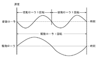
図6は、その各ローラの偏芯による速度変動を示す波形図である。一般的に、ローラの偏芯運動はその周期に応じて図のように変化する。このままでは、その速度変動を検出誤差として検出してしまう。そのため、1回転毎の移動時間、つまりは1回転毎のカウント値を基に移動時間を求めることにより、その速度変動による検出誤差を取り除くことが可能となる。よって図に示すように、駆動ローラ14の外周を従動ローラ16の外周の整数倍(図は2倍の場合を示す)とし、駆動ローラ14の少なくとも1回転毎(図では1回転毎)にその移動時間のカウント値をカウントすれば、駆動ローラ14だけでなく従動ローラ16の偏芯等によって生じる検出誤差をキャンセルすることができる。駆動ローラ14の外周を従動ローラ16の外周の比の整数倍とする場合も、同様な方法で検出誤差をキャンセルすることができる。このようにすることで、環境変化による駆動ローラ14の熱膨張(駆動ローラ14は、転写性やグリップ性の観点から芯金鉄のゴムローラが用いられ、駆動ローラ14が定着ユニット8に近いところに配設されていることからも、温度上昇によりゴムローラ径が膨張して中間転写ベルト12の搬送速度が徐々に増加する)によって速度変動するようなゆっくりした変化に対応できる。
FIG. 6 is a waveform diagram showing speed fluctuation due to eccentricity of each roller. In general, the eccentric motion of a roller changes as shown in the figure according to its period. In this state, the speed fluctuation is detected as a detection error. For this reason, by obtaining the movement time based on the movement time for each rotation, that is, the count value for each rotation, it is possible to remove the detection error due to the speed fluctuation. Therefore, as shown in the figure, the outer circumference of the driving
図7は、本発明の演算部32における一制御方法を示すフローチャートである。
図7を参照して制御動作の手順を説明する。まず、S10において、プリント動作等において駆動モータ4の立ち上げが開始され駆動モータ4が定常速に安定すると、S11にてカウンタ部30前段のクロック31のカウントクロックによるカウント値をゼロにクリアし、カウンタ部30からの割込許可と共にカウント開始をONに設定する。次に、S12にて中間転写ベルト12の速度制御を実行するか判断し、実行と判断されるとS13に進み、駆動モータ4の立ち上げ直後の最初のステップか判断する。最初の割込におけるカウント値は、カウント動作ONと検出信号の変化が同期しておらず正確な値ではないので、S14にて1回目の割込における制御を無視する。そして、S15にて割込カウント数:n=0にセットする。S16にてカウント部30からの割込を待ち、割込が発生するとS17に進み、割込カウントをn=n+1にインクリメントする。そしてS18にて、カウント部30からレジスタに転送されたn番目におけるカウンタ値:TCnをリードすると共に、RAM33にその値をメモリする。次に、S19にて最初からn≧8になるまではS16に戻りS16〜S18を繰り返す。
FIG. 7 is a flowchart showing one control method in the
The procedure of the control operation will be described with reference to FIG. First, in S10, when the
n=8に達するとS20に進み、従動ローラ16の角速度:Vn[mm/s]を算出する。算出の一方法は以下のとおりである。ここで、従動ローラ16の1/4回転のカウント値をTCnとすると、駆動ローラ14の1周期分のカウント値:Tcnとして、現求めたカウント値を含めて過去8回のカウント値を加算しTcnを求める。
Tcn=TCn−7+TCn−6+TCn−5+TCn−4+TCn−3+TCn−2
+TCn−1
+TCn
When n = 8, the process proceeds to S20, and the angular velocity of the driven roller 16: V n [mm / s] is calculated. One method of calculation is as follows . Here, when the count value of the 1/4 rotation of the driven
Tc n = TC n-7 + TC n-6 + TC n-5 + TC n-4 + TC n-3 + TC n-2
+ TC n-1
+ TC n
カウントクロックの最小カウント時間(サンプリング時間)をΔt[ms]とすると、Tcnにおけるカウント時間:Tn[ms]は、 Tn[ms]=Tcn×Δt より求められる。 When the count clock minimum count time (sampling time) and Delta] t [ms], the count time at Tc n: T n [ms] is determined from the T n [ms] = Tc n × Δt.
従動ローラ16の径+中間転写ベルト厚膜をr[mm]とすると、従動ローラ16の角速度:Vpn[mm/s]は、 Vpn[mm/s]=r×π×2/Tn×1000 より求められる。
When the diameter + intermediate transfer belt thick of the driven
次にS21に進み、ノイズ等による誤りカウントを排除する。誤りカウントの場合はS15からやり直す。ここでは、その判断を、目標速度をVs[mm/s]として±0.5%の範囲としている。前記範囲内の場合はS22に進み、操作速度(速度補正量):Vmn[mm/s]を算出する。算出の一方法は以下のとおりである。まず、目標速度:Vs[mm/s]との差分値(偏差):Ven[mm/s]を Ven[mm/s]=Vs−Vpnとして求める。 Next, in S21, error count due to noise or the like is eliminated. In the case of an error count, the process is repeated from S15. Here, the determination is made within a range of ± 0.5% with the target speed Vs [mm / s]. Proceeds to S22 in the case of the above range, the operation speed (speed correction amount) to calculate the Vm n [mm / s]. One method of calculation is as follows . First, the target speed: difference between Vs [mm / s] (deviation): Request Ve n [mm / s] as Ve n [mm / s] = Vs-Vp n.
一方、その差分値に対する積分速度Vein[mm/s]を、
Vein[mm/s]=Ven+Ven−1 、として求める。
この時、Ven,VeinはRAM33にメモリする。
以上より、操作速度:Vmn[mm/s]は、
Vmn[mm/s]=Kp×Ven+Ki×Vein+Kd×(Ven−Ven−1)+Vs
ただし、Kp:比例係数、Ki:積分係数、Kd:微分係数、から求められる。これは、PID制御と呼ばれるもので、パルス変化毎の細かい間隔で制御可能になるので、中間転写ベルト12の厚み偏差による速度変化や転写紙Pの駆動ローラ14を通過する際の転写紙Pの挙動による速度変化等の外乱による短時間の変動の影響を受ける場合に有効である。なお、外乱等による短時間の変動の影響が少ないと判断される場合は、微分係数:Kdを乗じている微分項を無くしてPI制御にしてもよい。
On the other hand, the integrated velocity for the difference value Vei n [mm / s],
Vei n [mm / s] = Ve n + Ve n-1, obtained as.
In this case, Ve n, Vei n is memory to RAM33.
From the above, the operating speed: Vm n [mm / s] is,
Vm n [mm / s] = Kp × Ve n + Ki × Vei n + Kd × (Ve n -Ve n-1) + Vs
However, it is obtained from Kp: proportional coefficient, Ki: integral coefficient, Kd: differential coefficient. This is called PID control, and can be controlled at fine intervals for each pulse change. Therefore, the speed change due to the thickness deviation of the
なお、S22で操作速度を求める基本は、目標速度:Vs[mm/s]との差分値:Ven[mm/s]=Vs−Vnを、これに補正係数Kを掛けて、ΔV[mm/s]=K×Venとして求めることである。 The basic seeking operation speed in S22, the target speed: difference between Vs [mm / s]: the Ve n [mm / s] = Vs-V n, by multiplying the correction coefficient K to, [Delta] V [ it is to obtain as mm / s] = K × Ve n.
次に、S22にて求めた速度補正量に従い、S23にてモータ駆動部34に対して現速度より変化させたモータ駆動クロックを出力するようにモータ駆動部34に対して指令を出し、中間転写ベルト12の速度制御が行われる。S25にてプリント動作等が終了か判断し駆動モータ4の停止と判断されると、S26に進み駆動モータ4を立ち下げて処理は終了する。
Next, in accordance with the speed correction amount obtained in S22, a command is issued to the
以上述べた中間転写ベルトの速度制御動作を実行させるために、前記動作手順を汎用のプログラム言語によりコンピュータプログラムとして記述し、かつ、このプログラムをフレキシブルディスク、CD−ROM等の任意の記録媒体に記録し、これを画像形成装置のコンピュータに読み取らせることで本発明に係る速度制御を容易に実施することができる。 In order to execute the speed control operation of the intermediate transfer belt described above, the operation procedure is described as a computer program in a general-purpose program language, and this program is recorded on an arbitrary recording medium such as a flexible disk or a CD-ROM. Then, the speed control according to the present invention can be easily performed by causing the computer of the image forming apparatus to read it.
以上のように本発明に係る画像形成装置は多色のカラー画像形成装置において有用であり、特に高画質を指向するカラー画像形成装置に用いるのに適している。 As described above, the image forming apparatus according to the present invention is useful in a multicolor image forming apparatus, and is particularly suitable for use in a color image forming apparatus directed to high image quality.
10・・感光体ドラム、11・・現像ユニット、12・・中間転写ベルト、13・・一次転写ローラ、14・・駆動ローラ、15・・テンションローラ、16・・従動ローラ、17・・二次転写ローラ、18・・光学センサ、19・・従動ローラの芯金部分、20・・検知物(位置マーク) 10 .... photosensitive drum, 11 .... developing unit, 12 .... intermediate transfer belt, 13 .... primary transfer roller, 14 .... driving roller, 15 .... tension roller, 16 .... secondary roller, ...... secondary roller Transfer roller, 18 ... Optical sensor, 19 ... Core metal part of driven roller, 20 ... Object to be detected (position mark)
Claims (3)
従動ローラの周面に略等間隔に設けた複数の検知物及び非検知物と、
検知物を検知する手段と、
前記検知物の検知に伴い発生するパルス信号の立ち上がりから立ち下がり又は立ち下がりから立ち上がり間のクロックパルス数をカウントするカウント手段と、
前記カウント手段によるクロックパルス数のカウント値から前記従動ローラの移動速度を算出する速度算出手段と、
従動ローラの移動速度の目標速度を記憶する手段と、
前記算出した移動速度と前記目標速度から、従動ローラが一定速度となるような速度補正量を求める補正量算出手段と、
前記速度補正量に基づき、モータを駆動させるモータ駆動手段を備えていることを特徴とする画像形成装置。 In an image forming apparatus provided with an endless belt stretched by a driving roller and a driven roller, which carries a toner image formed of a plurality of colors of toner and transfers the toner image to a transfer material.
A plurality of detected objects and non-detected objects provided at substantially equal intervals on the peripheral surface of the driven roller;
Means for detecting the detected object;
Count means for counting the number of clock pulses between the rising edge and the falling edge of the pulse signal generated along with the detection of the detected object, or between the falling edge and the rising edge;
Speed calculating means for calculating the moving speed of the driven roller from the count value of the number of clock pulses by the counting means;
Means for storing a target speed of the driven speed of the driven roller;
A correction amount calculating means for obtaining a speed correction amount so that the driven roller becomes a constant speed from the calculated moving speed and the target speed;
An image forming apparatus comprising: motor driving means for driving a motor based on the speed correction amount.
前記駆動ローラは、従動ローラの外周の整数倍の外周を有することを特徴とする画像形成装置。 The image forming apparatus according to claim 1.
The image forming apparatus, wherein the driving roller has an outer periphery that is an integral multiple of the outer periphery of the driven roller.
従動ローラの周面に略等間隔に設けた複数の検知物の検知に伴い発生するパルス信号の立ち上がりから立ち下がり又は立ち下がりから立ち上がり間のクロックパルス数をカウントするカウント手段と、A counting means for counting the number of clock pulses between the rising edge and the falling edge of the pulse signal generated along with the detection of a plurality of detection objects provided at substantially equal intervals on the peripheral surface of the driven roller;
前記カウント手段によるクロックパルス数のカウント値から前記従動ローラの移動速度を算出する速度算出手段と、Speed calculating means for calculating the moving speed of the driven roller from the count value of the number of clock pulses by the counting means;
従動ローラの移動速度の目標速度を記憶する手段と、Means for storing a target speed of the driven speed of the driven roller;
前記算出した移動速度と従動ローラの移動速度から、従動ローラが一定速度となるような速度補正量を求める補正量算出手段と、A correction amount calculating means for obtaining a speed correction amount so that the driven roller becomes a constant speed from the calculated moving speed and the moving speed of the driven roller;
前記速度補正量に基づきモータを駆動させるモータ駆動手段、Motor driving means for driving the motor based on the speed correction amount;
として機能させるためのプログラム。Program to function as.
Priority Applications (1)
| Application Number | Priority Date | Filing Date | Title |
|---|---|---|---|
| JP2004211885A JP4425082B2 (en) | 2004-07-20 | 2004-07-20 | Image forming apparatus and program |
Applications Claiming Priority (1)
| Application Number | Priority Date | Filing Date | Title |
|---|---|---|---|
| JP2004211885A JP4425082B2 (en) | 2004-07-20 | 2004-07-20 | Image forming apparatus and program |
Publications (2)
| Publication Number | Publication Date |
|---|---|
| JP2006030788A JP2006030788A (en) | 2006-02-02 |
| JP4425082B2 true JP4425082B2 (en) | 2010-03-03 |
Family
ID=35897180
Family Applications (1)
| Application Number | Title | Priority Date | Filing Date |
|---|---|---|---|
| JP2004211885A Expired - Fee Related JP4425082B2 (en) | 2004-07-20 | 2004-07-20 | Image forming apparatus and program |
Country Status (1)
| Country | Link |
|---|---|
| JP (1) | JP4425082B2 (en) |
Families Citing this family (3)
| Publication number | Priority date | Publication date | Assignee | Title |
|---|---|---|---|---|
| JP5549044B2 (en) * | 2005-07-07 | 2014-07-16 | 株式会社リコー | Drive control device and image forming apparatus |
| JP5128896B2 (en) * | 2007-10-23 | 2013-01-23 | 京セラドキュメントソリューションズ株式会社 | Transfer belt unit and image forming apparatus having the same |
| JP5483185B2 (en) * | 2010-03-17 | 2014-05-07 | 株式会社リコー | Image forming apparatus |
-
2004
- 2004-07-20 JP JP2004211885A patent/JP4425082B2/en not_active Expired - Fee Related
Also Published As
| Publication number | Publication date |
|---|---|
| JP2006030788A (en) | 2006-02-02 |
Similar Documents
| Publication | Publication Date | Title |
|---|---|---|
| JP5549044B2 (en) | Drive control device and image forming apparatus | |
| JP3658262B2 (en) | Image forming apparatus | |
| JP4391898B2 (en) | Belt drive control device, belt device and image forming apparatus | |
| JP3344614B2 (en) | Belt transport device | |
| JP5201520B2 (en) | Image forming apparatus | |
| JP2009036914A (en) | Image forming apparatus and image forming method | |
| JPS6259977A (en) | Image forming device | |
| JPH07140844A (en) | Detector for angular velocity of rotating member for image forming device | |
| JPH07303385A (en) | Rotary body drive controller | |
| JP2000047547A (en) | Image forming device | |
| JP5196759B2 (en) | Image forming apparatus | |
| JP4667819B2 (en) | Belt drive control device, belt device and image forming apparatus | |
| JP4425082B2 (en) | Image forming apparatus and program | |
| JP4263583B2 (en) | Image forming apparatus | |
| JP5556092B2 (en) | Belt drive control device, belt drive control method, and image forming apparatus | |
| JP4667033B2 (en) | Conveyance control method and image forming apparatus | |
| CN100517115C (en) | Drive control device and image forming apparatus | |
| JP2005017768A (en) | Multi-color image forming apparatus | |
| JP5369445B2 (en) | Motor control apparatus, image forming apparatus, and program | |
| JP4503417B2 (en) | Image forming apparatus | |
| US20060093410A1 (en) | Image forming apparatus and method for controlling the same | |
| JP2001109353A (en) | Image forming device | |
| JP4538251B2 (en) | Image forming apparatus | |
| JP2001066909A (en) | Moving speed controller | |
| JP2001282073A (en) | Image forming device |
Legal Events
| Date | Code | Title | Description |
|---|---|---|---|
| A621 | Written request for application examination |
Free format text: JAPANESE INTERMEDIATE CODE: A621 Effective date: 20070115 |
|
| A977 | Report on retrieval |
Free format text: JAPANESE INTERMEDIATE CODE: A971007 Effective date: 20090702 |
|
| A131 | Notification of reasons for refusal |
Free format text: JAPANESE INTERMEDIATE CODE: A131 Effective date: 20090706 |
|
| A521 | Written amendment |
Free format text: JAPANESE INTERMEDIATE CODE: A523 Effective date: 20090903 |
|
| A131 | Notification of reasons for refusal |
Free format text: JAPANESE INTERMEDIATE CODE: A131 Effective date: 20090930 |
|
| A521 | Written amendment |
Free format text: JAPANESE INTERMEDIATE CODE: A523 Effective date: 20091111 |
|
| TRDD | Decision of grant or rejection written | ||
| A01 | Written decision to grant a patent or to grant a registration (utility model) |
Free format text: JAPANESE INTERMEDIATE CODE: A01 Effective date: 20091208 |
|
| A01 | Written decision to grant a patent or to grant a registration (utility model) |
Free format text: JAPANESE INTERMEDIATE CODE: A01 |
|
| A61 | First payment of annual fees (during grant procedure) |
Free format text: JAPANESE INTERMEDIATE CODE: A61 Effective date: 20091208 |
|
| R150 | Certificate of patent or registration of utility model |
Ref document number: 4425082 Country of ref document: JP Free format text: JAPANESE INTERMEDIATE CODE: R150 Free format text: JAPANESE INTERMEDIATE CODE: R150 |
|
| FPAY | Renewal fee payment (event date is renewal date of database) |
Free format text: PAYMENT UNTIL: 20121218 Year of fee payment: 3 |
|
| FPAY | Renewal fee payment (event date is renewal date of database) |
Free format text: PAYMENT UNTIL: 20131218 Year of fee payment: 4 |
|
| LAPS | Cancellation because of no payment of annual fees |