JP4409707B2 - Pushbutton mechanism and watch equipped with the mechanism - Google Patents
Pushbutton mechanism and watch equipped with the mechanism Download PDFInfo
- Publication number
- JP4409707B2 JP4409707B2 JP2000083585A JP2000083585A JP4409707B2 JP 4409707 B2 JP4409707 B2 JP 4409707B2 JP 2000083585 A JP2000083585 A JP 2000083585A JP 2000083585 A JP2000083585 A JP 2000083585A JP 4409707 B2 JP4409707 B2 JP 4409707B2
- Authority
- JP
- Japan
- Prior art keywords
- arm
- push button
- mechanism according
- lever
- pin
- Prior art date
- Legal status (The legal status is an assumption and is not a legal conclusion. Google has not performed a legal analysis and makes no representation as to the accuracy of the status listed.)
- Expired - Fee Related
Links
Images


Classifications
-
- G—PHYSICS
- G04—HOROLOGY
- G04B—MECHANICALLY-DRIVEN CLOCKS OR WATCHES; MECHANICAL PARTS OF CLOCKS OR WATCHES IN GENERAL; TIME PIECES USING THE POSITION OF THE SUN, MOON OR STARS
- G04B3/00—Normal winding of clockworks by hand or mechanically; Winding up several mainsprings or driving weights simultaneously
- G04B3/04—Rigidly-mounted keys, knobs or crowns
- G04B3/048—Operation exclusively by axial movement of a push-button, e.g. for chronographs
-
- G—PHYSICS
- G04—HOROLOGY
- G04B—MECHANICALLY-DRIVEN CLOCKS OR WATCHES; MECHANICAL PARTS OF CLOCKS OR WATCHES IN GENERAL; TIME PIECES USING THE POSITION OF THE SUN, MOON OR STARS
- G04B27/00—Mechanical devices for setting the time indicating means
- G04B27/004—Mechanical devices for setting the time indicating means having several simultaneous functions, e.g. stopping or starting the clockwork or the hands
-
- H—ELECTRICITY
- H01—ELECTRIC ELEMENTS
- H01H—ELECTRIC SWITCHES; RELAYS; SELECTORS; EMERGENCY PROTECTIVE DEVICES
- H01H13/00—Switches having rectilinearly-movable operating part or parts adapted for pushing or pulling in one direction only, e.g. push-button switch
- H01H13/02—Details
- H01H13/26—Snap-action arrangements depending upon deformation of elastic members
-
- H—ELECTRICITY
- H01—ELECTRIC ELEMENTS
- H01H—ELECTRIC SWITCHES; RELAYS; SELECTORS; EMERGENCY PROTECTIVE DEVICES
- H01H2227/00—Dimensions; Characteristics
- H01H2227/032—Operating force
- H01H2227/034—Regulation of operating force
-
- H—ELECTRICITY
- H01—ELECTRIC ELEMENTS
- H01H—ELECTRIC SWITCHES; RELAYS; SELECTORS; EMERGENCY PROTECTIVE DEVICES
- H01H2300/00—Orthogonal indexing scheme relating to electric switches, relays, selectors or emergency protective devices covered by H01H
- H01H2300/016—Application timepiece
Landscapes
- Physics & Mathematics (AREA)
- General Physics & Mathematics (AREA)
- Measurement Of Unknown Time Intervals (AREA)
- Push-Button Switches (AREA)
- Electric Clocks (AREA)
Description
【0001】
【発明の属する技術分野】
本発明は、正しく作動していることの触覚的または聴覚的指示を使用者に与えるためにクリック効果を生じ、また、装置の適所に配設された場合に、機械的制御要素の反力に抗して作用するまたは電気接点を閉じるために押しボタンに加えなければならない力を調節できるようにする押しボタン機構に関する。
【0002】
本発明は、特に時計に適するものであり、詳細には、当該機構を備える押しボタンが、クロノグラフの従来の3機能、すなわち、ストップ/スタートおよびゼロリセットを制御できるクロノグラフまたはストップウォッチに適する。
【0003】
【従来の技術】
押しボタンは、概略、心棒および/または一端で閉鎖された小さな中空円筒より成る極めて単純な制御手段であり、装置の枠を通る通路で滑動し、心棒の頭部を外部方向に押す弾性手段によって非作動または休止位置に保持され、頭部に行使される圧力によって作動位置にさせられる。弾性手段は主に、通路に収容され枠により支持されたコイルばねによるか、または、その少なくとも一端で枠に確保され、心棒の反対の端を直接かつ/または間接に頭部に押しつける板ばねまたは線ばねによる、いずれか一方によって形成される。
【0004】
部屋の照明または音響源のスイッチオンといった、装置の適正な作動が容易に知覚できる用途では、そうした制御手段は、材料の選択および組立技法において多数の可能な変更が存在しても、最も単純な実装態様で良好となり得る。
【0005】
他の場合には、押しボタンに圧力を行使する使用者が、それを視覚的に確認できる位置にいない場合でも、選択した機能が本当に始動されたという確信をもって感じる必要がある。このことは、機械式または電子式を問わず、適切な押しボタンを押すことによって計時を開始および停止する指令を使用者が見ていなければならない事象と同期させなければならないような場合のクロノグラフにおいて特に当てはまる。その場合、クロノグラフの正しい作動を視覚的に確認することは不可能である。
【0006】
こうした短所を克服するために、使用者が圧力を行使した時に知覚できるクリック効果を生じるために各種の装置が提起されてきた。米国特許第4,451,719号では、心棒がコイルばねの復原力に抗して管内を滑動し、心棒には、機能の始動の直前にクリック効果を生じるために管の頸部を通過しなければならない弾性要素が備わっている。こうした装置は、クリック効果が弾性要素が磨耗するにつれて徐々に不明瞭になるという短所があり、また、行使される圧力の調節は、ばねの圧縮率の選択により行われるにすぎない。
【0007】
日本実用新案第7812/79号では、弾性手段は、一端がケースの底部に固定され、押しボタンを非作動位置に保持するために使用される自由端が押しボタンのほぼ長手方向にU字形に曲げられた部分により延長されている、金属帯により形成されている。やはり弾性であるその自由分岐は、プレートに到る心棒に接し、その一端に、心棒が通過しなければならず、圧力が行使された時にクリック効果を生じる肉厚部を有する。この構成において指摘される点は、行使される圧力が最終的に、帯自体にもとづく押しボタンへの力および、U字形延長部の自由部分にもとづく帯と心棒の結合点の相対位置への力の2つの力の合力であり、従って、避けられない製造および取付け公差は、押しボタンの頭部に行使されなければならない力に関して、ある装置と別の装置との間で管理不可能な変動をもたらすことになる。
【0008】
複雑な連鎖の制御装置として使用される押しボタンの場合、行使される圧力は、クリック効果がもはや良好な形で知覚されないようなものとなり得ることが最終的に指摘される。
【0009】
【発明が解決しようとする課題】
本発明の目的は、非作動位置での弾性復原手段が板ばね状であり、押しボタンの頭部に行使される力が容易に調節可能である、クリック装置を押しボタン機構に備えることによって、そうした従来技術の短所を克服することである。
【0010】
【課題を解決するための手段】
従って、本発明は、復原手段を形成し、押しボタンによって行使される力Fの作用によりクリック効果を生じるために、平面支持材に平行な平面において相互に対して可動する第1および第2の部材を備える機械的または電気的機能を始動するための押しボタン機構である。第1の部材は支持材に取付けられた支柱を心軸にその一端によって回転するてこにより形成されている。そのてこは支柱に対して三角形に構成された他の2個のピンを備えている。全体として細長い形状の第2の部材は第1と第2のアームを結合している基部を区切るほぼU字形の切込み部を備えている。基部は支持材に取付けられたガイドランプに沿って滑動するように意図されたガイド手段と始動される機能のための少なくとも1個の制御手段を備えている。第2の部材の第1のアームは剛性であり、その端部がてこの第1のピンに回転可能に取付けられており、第2のアームは柔軟であり、てこの第2のピンが非作動位置において係合する切欠きをその自由端に有している。切欠きはU字形切込み部の外側方向に向けられた外縁を有する嘴に連なっており、第2のピンが切欠きに対して、押しボタンを介して剛性アームに力が行使された時に柔軟アームを圧縮することによって滑動し、一方の位置から他方の位置へ通過することによってクリック効果を生じさせるものであることを特徴とする押しボタン機構に関する。
【0011】
前述において、U字形切込み部を備える細長い形状を有する第2の部材の構成は明らかに、装置の他の構成要素との組立の問題のためだけで、各アームの縁が必ずしも全部は平行ではないあらゆる部材をより全体的に指示する。
【0012】
時計の場合のように、高さの縮小が求められる実施態様では、機構を形成する2個の部材は均一な厚さのプレートに切断され、てこはほぼ三角形の形状を有し、U字形部材は剛性であるために十分に幅の広い1個のアームおよび柔軟であるために十分に幅の狭い1個のアームを有する。ある程度の柔軟性を有する限り、あらゆる材料がこれらの2個の部材を形成できるが、時計の場合のように、相当の寿命が要求される用途では、ばね鋼といった金属または合金が好適に選択されるはずである。
【0013】
非作動位置から作動位置へ移行するために必要な力は、てこの2個のピンおよび支柱の相対位置、第2の部材の柔軟アームの長さまたは柔軟アームの端に配置された先端の外縁の傾斜といった、2個の部材の幾何学形状を指定する段階において規定できる。その後者の解決、先端の外縁の傾斜は、異なる圧力を要する機構を、単に先端の縁の適切な機械加工によって同一の未加工品から製作できるという利点を有する。
【0014】
本発明の別の態様によれば、非作動位置から作動位置へ移行するために必要な力は、装置への機構の取付け後に調節できる。そのために、機構は、押しボタンに適用されなければならない力Fを調節する手段を備えており、この手段は、柔軟アームの屈曲点または剛性アームに対するその初期距離を修正するために切込み部に面する縁の間に配設される。第1の実施態様によれば、この調節手段は、屈曲点を修正するために剛性アームおよび柔軟アームの縁に平行に配置された対面する切欠きの間に複数の位置を占めることが可能な円柱体によるピンにより形成される。別の実施態様によれば、ピンは楕円形の溝付き胴体をしており、その向きに従って付加的な調節可能な力を発生させることによって、カムとして作用するように柔軟アームおよび剛性アームの縁に配置された対面する2個の溝付き切欠きの間に配置される。このピンは、第2の部材の2個のアームの間に単純に締付けるかまたは結合もしくは溶接するかのいずれか一方によって保持できる。この構成は、特にこの機構が複雑な連鎖で作用するように意図されている場合に、避けられない製造公差のために機構ごとに変化し得る反力にかかわらず、同一の製造ラインに由来する全部の装置の押しボタンについて同一の始動力を持たせるために特に好適である。この構成はまた、同一装置が複数の押しボタンを備えており、従って行使されなければならない力が、それらが作用する機構が向き合っており、当然、異なる反力である場合でさえ、全部の押しボタンに関して同一である場合にも好適である。これは、異なる機構に別々に作用する、スタート/ストップ押しボタンおよびゼロリセット押しボタンを一般に備えるクロノグラフの場合に当てはまる。
【0015】
U字形機構の第2の部材の基部に配置された制御手段は、ガイド手段と併合させることができ、最も単純な実施態様では、前記第2の部材の基部に到り、支持材の方向に向けられた支柱によって形成することができる。また、この組み合わされた制御・ガイド手段は、前記第2の部材の全体平面に垂直な平面に曲げられた基部の延長部によって形成することができる。押しボタンにより直接または間接に剛性アームに圧力が行使されると、支柱はガイドランプに沿って滑動し、電気接点を閉じたりまたは機械的要素を動かす。ガイドランプは、支持材またはそれに取付けられた部材に配設された横長の穴によって形成でき、2つの限界位置の間で支柱の行程を制限し、以下の詳細な説明においてわかる通り、例えば歯付きクラウンを1歯だけ順送りさせる。
【0016】
別の実施態様によれば、機構は、上述の制御・ガイド手段および、2つの機能を同時にまたは連続的に始動させることができるように、例えば基部を延長したアームにより形成される第2の制御手段を備える。
【0017】
さらに、第1および第2の部材の幾何学形状に作用することによって、本発明による機構は、技術的または美観的理由で装置の中間部のどこにでも配置できる押しボタンに関して、始動される部材の位置決めにおいて大きな自由を付与することがわかるはずである。
【0018】
本発明の他の特徴および利益は、添付図面に関して非限定的な例として示す、各種実施態様の以下の説明において明白となるであろう。
【0019】
【発明の実施の形態】
図1は、時計ムーブメントのプレートといった、いずれかの底部とし得る平面支持材2または、それに付加された取付け部材に取付けられた、全体参照番号1によって指示された機構を示す。機構は非作動位置で示されている。すなわち、押しボタン4にいかなる力も加えられていない場合を示す。支持材2には、機構1によって作動する機械的制御部材がてこ5により略示されており、また、閉じられる電気接点が接点板6によって略示されており、電気接点は本発明による少なくとも1個の機構を含む装置の設計に応じた、唯一の機能、または2つ以上の機械的/電気的機能を有する。機構1は本質的に、平面支持材2に対し平行な、相互に可動する2個の部材10および20を備える。
【0020】
第1の部材10は、支持材2に取付けられた支柱12を心軸にして回転するてこ11によって形成される。このてこ11は、支柱12と共に三角形に配置された他の2個のピン14および16を含む。図1の理解を助けるために、てこ11に取付けられた2個のピン14および16の有効部分がてこ11の表面の上に図示されており、これらの2個のピンは平面支持材2に向けて、すなわち、ピボット支柱12と同じ方向に向けられている。従って、この第1の部材10は全体として三角形であり、その精確な輪郭は、機構が配設されるアセンブリの他の構成要素に左右される。
【0021】
全体参照番号20によって指示された第2の部材は、細長く、その中央部に、基部22、第1の剛性アーム28と第2の柔軟アーム32を区分するU字形の切込み部21を備える。剛性アーム28の端部29は、てこ11の第1のピン14に回転可能に取付けられている。第2の柔軟アーム32の自由端33は、U字形切込み部21の外側方向に向いている外縁38を有する嘴状先端36に連なる切り欠き34を有する。図1に示すように機構が非作動状態である時、てこ11に取付けられた第2のピン16は、2個のアーム28および32の微弱な締付けにより切り欠き34の底部に押しつけられて保持されて位置づけられている。基部22は、基部22に到る支柱25の形態として示された、機構支持材に向かって垂直なガイド手段23を備える。また、このガイド手段23は、基部22の延長部を折り曲げることによっても形成できる。このガイド手段23は、支持材2に取付けられ、かつ支持材2に2本の脚によって固定された横棒により略示されているたガイドランプ3に沿って滑動するように取り付けられている。機械的または電気的機能を制御する手段24は、基部22の延長部26により、または、支柱25のようなガイド手段自体により形成できる。
【0022】
アームの剛性または逆に柔軟性の特性は、当業者にとって公知のいずれかの方法によって、詳細には各アームの各区間を変化させることによって得られる。最も経済的な実施形態では、第2の部材20は、剛性アーム28および柔軟アーム32を有するように2個のアームのそれぞれの幅を選定して、例えば金属薄板などの均一厚さの板から切断される。
【0023】
図2は、上述の機構の別の実施形態、押しボタン4によって剛性アーム28に力Fが適用された場合を示している。この機構は、柔軟アーム32の屈曲点を変えることができる調節手段40を備える点で図1に示した機構と異なる。この調節手段は、図3Aに示す通り、円柱体43により結合された2個の頭部42および44を備えるピン41によって形成される。ピン41は、剛性アーム28と柔軟アーム32の両側の縁に配設された切り欠き28aおよび32aの間で複数の位置を占めることができる。例えば、この形式の機構は4個の位置決め切り欠きが作成され、反力はピンの位置の関数として測定された。
【0024】
【0025】
表からわかるように、ある位置から次の位置へ移動させることにより反力を約10%変動させることができる。
【0026】
図示していないが、別の実施形態によれば、剛性アーム28および柔軟アーム32の相対する縁にそれぞれ、2個の楕円形の頭部47および48が胴体46により結合され、胴体の軸に沿って溝を備えるピン45(図3B参照)が間に挿入される、好ましくは溝付きの壁を有するただ1個の切り欠きを備えることができる。このピン45は、カムとして機能し、2個の対面する切り欠きの間で与えられる向きに従って、柔軟アームに機械的バイアスを生じさせ、反力を変えられるようにする。前述の通り、図2は、力Fが押しボタン4によって加えられた時に支持材2の上で機構が占める新しい位置を示している。てこ11は、第2の部材20を駆動するピン12を中心に回転運動を行う。この第2の要素20の基部22が、ガイドランプ3による直線運動となるように力が加えられるガイド手段23を備えているので、剛性アーム28は、ピン14を中心に回転を生じ、その回転はピン16を切り欠き34から外してクリック効果を生じさせ、先端36の外縁38に沿って滑動するように力を加える。先端36の縁38の初期傾斜に応じて、行使されなければならない力Fは多少大きくなる。この運動をもたらすことにより、ガイド手段23として機能する支柱25は、てこによって表現された機械的制御手段5を動かし、基部2の延長部26は電気接点6を閉じる。容易に想像できるように、部材5および6の構成に従って、それらの動作は同時または連続的とすることができる。押しボタンを解放すると、機構は柔軟アーム32の弾性復原力によって初期位置(図1)に戻る。
【0027】
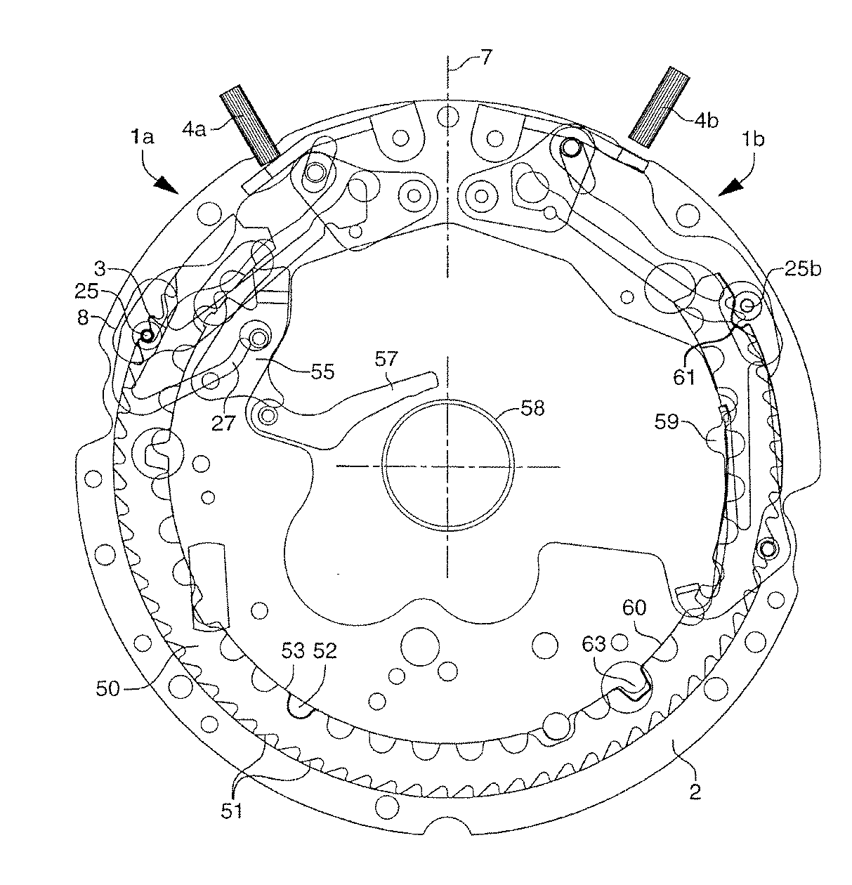
図4および5は、歯車列と全部の関係制御装置を外した状態で、巻上げ棒のピン7の各側に、背中合わせに配設された本発明に従った2個の機構を備えるクロノグラフを図示している。それらの機構は、それぞれクロノグラフのストップ/スタート機能およびゼロリセット機能を作動させるもので、押しボタン4aおよび4bによって駆動される。
【0028】
例として示された、これらの2個の機構が作用する連鎖は、詳細には2個の重畳環状制御カム50および60を備える米国特許第5,113,382号に詳述されたものと同じ形式である。ただし、機構1aおよび1bを含む部分を明瞭に示すためにそれらの連鎖は図示していない。
【0029】
機構1aは、一方で環状カム50に作用し、他方で1組のてこ55および57に作用する。カム50の外側部分には歯51が備わっており、押しボタンの押下ごとに支柱25によって1段ずつ回転駆動させられる。カム50の内側部分には規則的連続の切欠き52およびスタッド53が備わっており、その数は各々、歯51の数の半分である。非作動位置(図4)から始まり、図5は、押しボタン4aに力を加えることにより、支柱25aが、1段だけカム50を駆動するガイドランプ3として機能する横長の穴8に移動し、それはさらに、ストッパ部材59を第2のカム60に揺動させ、てこ55を介してブレーキ57に作用しそれを持ち上げる基部の延長部27によって、ゼロへのリセットおよびクロノグラフ58のホイールの解放を防止する。このようにして、機構1aは、2つの協働機能を、カムと同様に制御できる。
【0030】
ゼロリセット機構1bは同じ原理に従うが、対応するカム60は、その外側部分に、支柱25がかみ合う単一の駆動切り欠き61および、それを初期位置に戻す手段(図示せず)を有する。カムの内側部分は、文字盤の外周に配設された打ち子をカウンタのリセット用ハート形カムに当てさせる切り欠き63を備えているが、これらのハート形カムおよび打ち子は図に示していない。
【図面の簡単な説明】
【図1】 図1は、非作動位置にある本発明による機構の第1の実施形態の略斜視図である。
【図2】 図2は、押しボタンに力が加えられた時の本発明による機構の第2の実施形態の略斜視図である。
【図3】 図3Aおよび3Bは、2種類の調節ピンの拡大斜視図である。
【図4】 図4は、本発明による2つの機構を備えるオフ位置のクロノグラフの連鎖の一部の上面図である。
【図5】 図5は、スタート/ストップ押しボタンが押された時の図4の機構の一部を示す。
【符号の説明】
1 機構、2 平面支持材、3 ガイドランプ、4 押しボタン、5、11 てこ、20部材、21 切り込み、 22 基部、 23 ガイド手段 32 アーム。[0001]
BACKGROUND OF THE INVENTION
The present invention creates a click effect to give the user a tactile or audible indication of correct operation, and also reduces the reaction force of the mechanical control element when placed in place in the device. The present invention relates to a push button mechanism that allows to adjust the force that must be applied to the push button to act against or close the electrical contact.
[0002]
The present invention is particularly suitable for a timepiece, and in particular, a pushbutton with such a mechanism is suitable for a chronograph or stopwatch that can control the conventional three functions of a chronograph, namely stop / start and zero reset. .
[0003]
[Prior art]
A pushbutton is a very simple control means consisting roughly of a mandrel and / or a small hollow cylinder closed at one end, which is slid in a passage through the frame of the device and by elastic means that pushes the mandrel head outward. It is held in a non-actuated or resting position and is brought into the activated position by pressure exerted on the head. The elastic means is mainly a coil spring housed in the passage and supported by the frame, or a leaf spring or a spring that is secured to the frame at least at one end and presses the opposite end of the mandrel directly and / or indirectly against the head It is formed by either one of wire springs.
[0004]
In applications where proper operation of the device can be easily perceived, such as room lighting or acoustic source switching on, such control means are the simplest, even though there are many possible changes in material selection and assembly techniques. The implementation can be good.
[0005]
In other cases, the user who exerts pressure on the push button needs to feel confident that the selected function has actually been activated, even if it is not in a position where it can be visually confirmed. This is a chronograph where the command to start and stop timing by pressing the appropriate push button, whether mechanical or electronic, must be synchronized with the event that the user must see. This is especially true. In that case, it is impossible to visually confirm the correct operation of the chronograph.
[0006]
In order to overcome these disadvantages, various devices have been proposed to produce a click effect that can be perceived when a user exercises pressure. In U.S. Pat. No. 4,451,719, the mandrel slides within the tube against the restoring force of the coil spring, and the mandrel passes through the neck of the tube to produce a click effect just before function activation. It has elastic elements that must be present. Such devices have the disadvantage that the click effect is gradually obscured as the elastic element wears, and the adjustment of the pressure exerted is only made by the selection of the compression rate of the spring.
[0007]
In Japanese Utility Model No. 7812/79, the elastic means has one end fixed to the bottom of the case, and the free end used to hold the push button in the non-actuated position has a U-shape substantially in the longitudinal direction of the push button. It is formed by a metal strip that is extended by a bent portion. The free branch, which is also elastic, touches the mandrel to the plate and at one end has a thickened part that the mandrel must pass through and produces a click effect when pressure is exercised. The point to be pointed out in this configuration is that the pressure exerted is ultimately the force on the push button based on the band itself and the force on the relative position of the band and mandrel coupling point based on the free part of the U-shaped extension. Therefore, inevitable manufacturing and mounting tolerances result in uncontrollable variation between one device and another with respect to the force that must be exerted on the pushbutton head. Will bring.
[0008]
In the case of push buttons used as complex chain controllers, it is finally pointed out that the pressure exerted can be such that the click effect is no longer perceived in a good way.
[0009]
[Problems to be solved by the invention]
It is an object of the present invention to provide a push button mechanism with a click device in which the elastic restoring means in the non-actuated position is in the form of a leaf spring and the force exerted on the head of the push button can be easily adjusted. It is to overcome such disadvantages of the prior art.
[0010]
[Means for Solving the Problems]
Therefore, the present invention forms the restoring means and produces the click effect by the action of the force F exercised by the push button, so that the first and second movable relative to each other in a plane parallel to the plane support member. A push button mechanism for initiating a mechanical or electrical function comprising a member. The first member is formed by a lever that rotates around one end of a support column attached to a support member about a mandrel. The lever has two other pins configured in a triangle with respect to the column. The generally elongated second member includes a generally U-shaped notch that delimits the base connecting the first and second arms. The base comprises guide means intended to slide along a guide ramp mounted on the support and at least one control means for the function to be triggered. The first arm of the second member is rigid and has an end rotatably attached to the lever first pin, the second arm is flexible and the lever second pin is non- It has a notch at its free end that engages in the operating position. The notch is connected to a ridge having an outer edge directed in the outward direction of the U-shaped notch, and the flexible arm when the force is exerted on the rigid arm via the push button against the notch The present invention relates to a push button mechanism that slides by compressing and generates a click effect by passing from one position to the other position.
[0011]
In the foregoing, the configuration of the second member having an elongated shape with a U-shaped cut is apparently only due to assembly issues with the other components of the device, and the edges of each arm are not necessarily all parallel. All parts are indicated more generally.
[0012]
In an embodiment where a reduction in height is required, as in the case of a watch, the two members forming the mechanism are cut into a plate of uniform thickness, the lever has a generally triangular shape, and a U-shaped member. Has one arm that is sufficiently wide to be rigid and one arm that is sufficiently narrow to be flexible. Any material can form these two parts as long as they have a certain degree of flexibility, but in applications where a considerable life is required, such as in the case of watches, metals or alloys such as spring steel are preferably selected. Should be.
[0013]
The force required to move from the non-actuated position to the actuated position is the relative position of the two pins and struts of the lever, the length of the flexible arm of the second member or the outer edge of the tip located at the end of the flexible arm Can be defined at the stage of designating the geometric shapes of the two members, such as the slope of. The latter solution, the inclination of the outer edge of the tip, has the advantage that a mechanism that requires different pressures can be made from the same blank, simply by appropriate machining of the tip edge.
[0014]
According to another aspect of the invention, the force required to transition from the non-actuated position to the actuated position can be adjusted after mounting the mechanism to the device. To that end, the mechanism is provided with means for adjusting the force F that must be applied to the push button, this means facing the incision in order to modify the bending point of the flexible arm or its initial distance to the rigid arm. Between the edges. According to the first embodiment, the adjusting means can occupy a plurality of positions between facing notches arranged parallel to the edges of the rigid and flexible arms to correct the bending point. It is formed by a pin made of a cylindrical body. According to another embodiment, the pin has an elliptical grooved body and the edges of the flexible arm and the rigid arm to act as a cam by generating an additional adjustable force according to its orientation. Between the two grooved notches facing each other. The pin can be held either simply by clamping or joining or welding between the two arms of the second member. This configuration comes from the same production line, regardless of reaction forces that can vary from mechanism to mechanism due to unavoidable manufacturing tolerances, especially when the mechanism is intended to work in a complex chain It is particularly suitable for having the same starting force for the push buttons of all devices. This configuration also provides that the same device has multiple push buttons, so that the force that must be exercised is the entire push, even if the mechanisms on which they operate are facing each other and of course different reaction forces. It is also suitable when the buttons are the same. This is true for chronographs that typically have a start / stop push button and a zero reset push button that act on different mechanisms separately.
[0015]
The control means arranged at the base of the second member of the U-shaped mechanism can be merged with the guide means, and in the simplest embodiment it reaches the base of the second member and in the direction of the support material. Can be formed by oriented struts. Further, the combined control / guide means can be formed by an extension of the base bent to a plane perpendicular to the entire plane of the second member. When pressure is exerted on the rigid arm directly or indirectly by the push button, the column slides along the guide ramp, closing the electrical contact or moving the mechanical element. The guide ramp can be formed by an oblong hole disposed in the support or a member attached to it, limiting the strut travel between the two limit positions, as can be seen in the detailed description below, e.g. toothed Move the crown forward by one tooth.
[0016]
According to another embodiment, the mechanism comprises a second control, for example formed by an arm with an extended base, so that the control and guide means described above and the two functions can be activated simultaneously or sequentially. Means.
[0017]
Furthermore, by acting on the geometry of the first and second members, the mechanism according to the invention allows the member to be activated with respect to a push button that can be placed anywhere in the middle of the device for technical or aesthetic reasons. It should be seen that it provides great freedom in positioning.
[0018]
Other features and advantages of the present invention will become apparent in the following description of various embodiments, given by way of non-limiting example with reference to the accompanying drawings.
[0019]
DETAILED DESCRIPTION OF THE INVENTION
FIG. 1 shows a mechanism indicated by the general reference numeral 1 attached to a
[0020]
The
[0021]
The second member, indicated by the
[0022]
The stiffness or conversely flexibility characteristics of the arms can be obtained by any method known to those skilled in the art, in particular by changing each section of each arm. In the most economical embodiment, the
[0023]
FIG. 2 shows another embodiment of the mechanism described above, where a force F is applied to the
[0024]
As can be seen from the table, the reaction force can be varied by about 10% by moving from one position to the next.
[0026]
Although not shown, according to another embodiment, two
[0027]
4 and 5 show a chronograph with two mechanisms according to the invention arranged back to back on each side of the pin 7 of the winding rod, with the gear train and all relational control devices removed. It is shown. These mechanisms actuate the chronograph stop / start and zero reset functions, respectively, and are driven by
[0028]
The chain in which these two mechanisms act, shown by way of example, is the same as that detailed in US Pat. No. 5,113,382, specifically comprising two overlapping
[0029]
The
[0030]
The zero
[Brief description of the drawings]
FIG. 1 is a schematic perspective view of a first embodiment of a mechanism according to the invention in a non-actuated position.
FIG. 2 is a schematic perspective view of a second embodiment of the mechanism according to the invention when a force is applied to the push button.
FIGS. 3A and 3B are enlarged perspective views of two types of adjustment pins.
FIG. 4 is a top view of a portion of an off-position chronograph chain comprising two mechanisms according to the present invention.
FIG. 5 shows a portion of the mechanism of FIG. 4 when a start / stop push button is pressed.
[Explanation of symbols]
DESCRIPTION OF SYMBOLS 1 Mechanism, 2 Planar support material, 3 Guide lamp, 4 Push button, 5, 11 Lever, 20 member, 21 Cut, 22 Base, 23 Guide means 32 Arm.
Claims (15)
Applications Claiming Priority (2)
| Application Number | Priority Date | Filing Date | Title |
|---|---|---|---|
| CH0746/99 | 1999-04-22 | ||
| CH74699 | 1999-04-22 |
Publications (2)
| Publication Number | Publication Date |
|---|---|
| JP2000321381A JP2000321381A (en) | 2000-11-24 |
| JP4409707B2 true JP4409707B2 (en) | 2010-02-03 |
Family
ID=4194245
Family Applications (1)
| Application Number | Title | Priority Date | Filing Date |
|---|---|---|---|
| JP2000083585A Expired - Fee Related JP4409707B2 (en) | 1999-04-22 | 2000-03-24 | Pushbutton mechanism and watch equipped with the mechanism |
Country Status (7)
| Country | Link |
|---|---|
| US (1) | US6270251B1 (en) |
| JP (1) | JP4409707B2 (en) |
| KR (1) | KR100779833B1 (en) |
| CN (1) | CN1140860C (en) |
| HK (1) | HK1032118A1 (en) |
| SG (1) | SG92696A1 (en) |
| TW (1) | TW434465B (en) |
Families Citing this family (9)
| Publication number | Priority date | Publication date | Assignee | Title |
|---|---|---|---|---|
| US7133033B1 (en) * | 1999-12-02 | 2006-11-07 | Advanced Input Devices Uk Limited | Actuator for a switch |
| US6952528B2 (en) * | 2003-12-03 | 2005-10-04 | Hewlett-Packard Development Company, L.P. | Variable force camera control |
| WO2006126258A1 (en) * | 2005-05-25 | 2006-11-30 | Fujitsu Limited | Rigidity adjusting mechanism |
| EP1933210B1 (en) * | 2006-12-13 | 2010-03-10 | Compagnie des Montres Longines, Francillon SA | Time setting mechanism for an hour indicator |
| JP5536623B2 (en) * | 2010-02-03 | 2014-07-02 | セイコーインスツル株式会社 | Chronograph clock |
| CH705461A1 (en) * | 2011-09-05 | 2013-03-15 | Manuf Roger Dubuis Sa | Control device for a timepiece. |
| CN106094489B (en) * | 2016-08-25 | 2018-10-09 | 烟台持久钟表有限公司 | A kind of anti-lost needle construction of Machine core of turret clock |
| EP3418813A1 (en) * | 2017-06-23 | 2018-12-26 | ETA SA Manufacture Horlogère Suisse | Push-crown control device for a compact portable object |
| EP4148504A1 (en) * | 2021-09-10 | 2023-03-15 | Blancpain SA | Time zone correction mechanism for a timepiece |
Family Cites Families (6)
| Publication number | Priority date | Publication date | Assignee | Title |
|---|---|---|---|---|
| GB2085621B (en) * | 1980-10-21 | 1984-07-25 | Suwa Seikosha Kk | Timepiece |
| CH645235GA3 (en) | 1981-04-23 | 1984-09-28 | ||
| JPH0684991B2 (en) * | 1984-01-13 | 1994-10-26 | シチズン時計株式会社 | Electronic clock |
| US5339297A (en) * | 1989-06-19 | 1994-08-16 | Seiko Epson Corporation | Switching arrangement for applying battery voltage to circuitry block in an analog timepiece |
| CH678911B5 (en) | 1990-04-12 | 1992-05-29 | Ebauchesfabrik Eta Ag | |
| CH686106B5 (en) * | 1993-03-23 | 1996-07-15 | Ebauchesfabrik Eta Ag | Chronograph watch with date indicator. |
-
2000
- 2000-03-24 JP JP2000083585A patent/JP4409707B2/en not_active Expired - Fee Related
- 2000-04-14 SG SG200002167A patent/SG92696A1/en unknown
- 2000-04-18 TW TW089107224A patent/TW434465B/en not_active IP Right Cessation
- 2000-04-20 KR KR1020000020872A patent/KR100779833B1/en not_active IP Right Cessation
- 2000-04-20 US US09/553,335 patent/US6270251B1/en not_active Expired - Lifetime
- 2000-04-21 CN CNB001069276A patent/CN1140860C/en not_active Expired - Fee Related
-
2001
- 2001-04-04 HK HK01102428A patent/HK1032118A1/en not_active IP Right Cessation
Also Published As
| Publication number | Publication date |
|---|---|
| JP2000321381A (en) | 2000-11-24 |
| CN1271873A (en) | 2000-11-01 |
| KR100779833B1 (en) | 2007-11-28 |
| US6270251B1 (en) | 2001-08-07 |
| KR20000071749A (en) | 2000-11-25 |
| SG92696A1 (en) | 2002-11-19 |
| HK1032118A1 (en) | 2001-07-06 |
| TW434465B (en) | 2001-05-16 |
| CN1140860C (en) | 2004-03-03 |
Similar Documents
| Publication | Publication Date | Title |
|---|---|---|
| JP4409707B2 (en) | Pushbutton mechanism and watch equipped with the mechanism | |
| JP4537655B2 (en) | Bi-directional rotating chronograph | |
| CN102458178B (en) | Device for adjusting the useful length of a bracelet, and corresponding bracelet clasp | |
| JP3054884B2 (en) | Stopwatch | |
| JP5014860B2 (en) | Second hand reset device for clock | |
| JP4443477B2 (en) | Device for stopping movement while setting time in a watch equipped with a tourbillon | |
| US5122995A (en) | Chronographic fly-back timepiece having a stop-start control for the fly-back hand | |
| CN102141773B (en) | Chronograph | |
| TWI269949B (en) | Chronograph coupling mechanism | |
| CA1039579A (en) | Drive mechanism for dough shaping apparatus | |
| JP3869039B2 (en) | Adjustable link for bracelet | |
| JP6469419B2 (en) | Zero reset device with independent hammer | |
| JP2002015637A (en) | Control device having snap function and wrist watch equipped with it | |
| JP5031882B2 (en) | Device for fixing straps or bracelets | |
| JP6751215B1 (en) | Balance wheel setting mechanism, clock movement and clock | |
| JP4244643B2 (en) | Clock with chronograph | |
| JPH0636039B2 (en) | Watch controller | |
| KR19990006732A (en) | Time setting device for watches | |
| JP5070217B2 (en) | Watch movement | |
| JP4279365B2 (en) | A watch with a mechanism to set the hands by direct action of the pull-out piece | |
| CN218037696U (en) | Timepiece mechanism and timepiece comprising such a mechanism | |
| RU2402055C2 (en) | Clock hammer | |
| JP4759217B2 (en) | Time-starting mechanism for watches equipped with a timer | |
| KR20020051840A (en) | Instantaneous drive mechanism for a date indicator | |
| JPH0616336Y2 (en) | Rod for opening and closing doors such as watches |
Legal Events
| Date | Code | Title | Description |
|---|---|---|---|
| A621 | Written request for application examination |
Free format text: JAPANESE INTERMEDIATE CODE: A621 Effective date: 20070202 |
|
| A131 | Notification of reasons for refusal |
Free format text: JAPANESE INTERMEDIATE CODE: A131 Effective date: 20090616 |
|
| A521 | Written amendment |
Free format text: JAPANESE INTERMEDIATE CODE: A523 Effective date: 20090622 |
|
| TRDD | Decision of grant or rejection written | ||
| A01 | Written decision to grant a patent or to grant a registration (utility model) |
Free format text: JAPANESE INTERMEDIATE CODE: A01 Effective date: 20091013 |
|
| A01 | Written decision to grant a patent or to grant a registration (utility model) |
Free format text: JAPANESE INTERMEDIATE CODE: A01 |
|
| A61 | First payment of annual fees (during grant procedure) |
Free format text: JAPANESE INTERMEDIATE CODE: A61 Effective date: 20091112 |
|
| R150 | Certificate of patent or registration of utility model |
Free format text: JAPANESE INTERMEDIATE CODE: R150 |
|
| FPAY | Renewal fee payment (event date is renewal date of database) |
Free format text: PAYMENT UNTIL: 20121120 Year of fee payment: 3 |
|
| FPAY | Renewal fee payment (event date is renewal date of database) |
Free format text: PAYMENT UNTIL: 20121120 Year of fee payment: 3 |
|
| FPAY | Renewal fee payment (event date is renewal date of database) |
Free format text: PAYMENT UNTIL: 20131120 Year of fee payment: 4 |
|
| R250 | Receipt of annual fees |
Free format text: JAPANESE INTERMEDIATE CODE: R250 |
|
| R250 | Receipt of annual fees |
Free format text: JAPANESE INTERMEDIATE CODE: R250 |
|
| R250 | Receipt of annual fees |
Free format text: JAPANESE INTERMEDIATE CODE: R250 |
|
| LAPS | Cancellation because of no payment of annual fees |