JP4381351B2 - Three-phase winding core - Google Patents
Three-phase winding core Download PDFInfo
- Publication number
- JP4381351B2 JP4381351B2 JP2005182205A JP2005182205A JP4381351B2 JP 4381351 B2 JP4381351 B2 JP 4381351B2 JP 2005182205 A JP2005182205 A JP 2005182205A JP 2005182205 A JP2005182205 A JP 2005182205A JP 4381351 B2 JP4381351 B2 JP 4381351B2
- Authority
- JP
- Japan
- Prior art keywords
- core
- wound
- phase
- iron core
- joint
- Prior art date
- Legal status (The legal status is an assumption and is not a legal conclusion. Google has not performed a legal analysis and makes no representation as to the accuracy of the status listed.)
- Active
Links
Images


Landscapes
- Manufacturing Cores, Coils, And Magnets (AREA)
Description
本発明は、珪素鋼板製の三相巻鉄心を用いた三相変圧器等の静止誘導機器に関する。 The present invention relates to a stationary induction device such as a three-phase transformer using a three-phase wound iron core made of a silicon steel plate.
三相変圧器に用いられる鉄心としては、積鉄心と巻鉄心とが知られており、積鉄心は比較的大形変圧器に適用される。積鉄心は、図7のようにコイル脚部1a〜1cと継鉄部2a、2bとから成り、各要素の接合部は45°でカットしたものを突合せている。三相積鉄心の場合、突合せ箇所3dが6箇所あり、この接合形状が特性に大きく影響し、接合箇所が少ないほど特性が改善する。また、変圧器の磁束の流れは鉄心の外側にあまり磁束が流れないことから、コーナー部は無駄に鉄心を使用している。積鉄心の製作工程においても、上継鉄部2a、下継鉄部2b、U相脚部1a、V相脚部1b、W相脚部1cと形状の種類数が多く、切断作業の段取り工数を多く要する。また、切断後の鉄心形成の際に珪素鋼板を、1枚ずつ積層する作業にも多くの工数を要している。
As an iron core used for a three-phase transformer, a stacked iron core and a wound iron core are known, and the loaded iron core is applied to a relatively large transformer. As shown in FIG. 7, the iron core includes coil leg portions 1 a to 1 c and
これに対し、図8に示す三相変圧器の巻鉄心の場合には、積鉄心の場合とは珪素鋼板の積層方向が異なり、磁束の流れに沿った形状をしているので積鉄心に比して鉄心使用量を抑えることができる。また、切断した珪素鋼板をそのまま積層し、円環状にしたのち、成形型を使用して、矩形状にして焼鈍工程に移ることができる。この工程は機械化が容易で、手作業が積鉄心より少ないため、低コストで製作できる。また、突合せ箇所3dが少なく、鉄心の損失が少なくなるため、利点が多い。
しかし大形巻鉄心を製造する場合には、珪素鋼板切断工程、丸巻工程、矩形成形工程、焼鈍工程の各工程での設備が大形化するため、巻鉄心の製作は困難であり、通常、大型の場合には、積鉄心で変圧器を製作することが多い。
On the other hand, in the case of the wound core of the three-phase transformer shown in FIG. 8, the stacking direction of the silicon steel sheet is different from that of the stacked core, and the shape is in line with the flow of magnetic flux. As a result, the amount of iron core used can be reduced. Further, after the laminated silicon steel plates are laminated as they are to form an annular shape, they can be formed into a rectangular shape by using a forming die and can be transferred to an annealing process. This process is easy to mechanize and can be manufactured at low cost because it requires less manual work than the core. Further, there are many advantages because there are few butted
However, when manufacturing large-sized wound cores, it is difficult to manufacture wound cores because the equipment in each process of the silicon steel sheet cutting process, round winding process, rectangular forming process, and annealing process is enlarged. In the case of large size, transformers are often made with iron cores.
三相巻鉄心の他の従来例としては、下記特許文献2から特許文献4に示す構造のものが知られている。図9から図11に、これらの特許文献2から特許文献4に記載された三相巻鉄心の構造の従来例を示す。
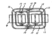
図9に記載された三相巻鉄心の従来例では、内側巻鉄心13,13を2個並べた外周に、第1の巻回体14をと第2の巻回体15を配置して外側巻鉄心16を形成している。この場合、内側巻鉄心13も外側巻鉄心14も、それぞれ、1箇所の切断部17を有している。
また、図10に記載された三相三脚形の巻鉄心20の従来例では、一対の内側巻鉄心21、21の外周には外側巻鉄心23、23が配置され、内側巻鉄心も外側巻鉄心も、2つの継目部分24、24を有している。また、前記一対の外側巻鉄心23、23の外周には外周巻鉄心27が配置され、それぞれの2つ傾斜面の継目部分28、28を有している。図10に記載された三相巻鉄心では、継目部分が脚部に位置しているため、高周波の振動による騒音が発生し、この騒音を抑えるために、あて板やバンドで固定することが必要である。
また、図11に記載された三相三脚巻鉄心の従来例では、巻鉄心隣接して配置された2個の内鉄心2と、これらの内鉄心2の外周を囲む外鉄心3とからなる三相三脚巻鉄心構造を有し、外鉄心3bのヨーク直線部の全域にラップ接合部5bを分散させて外鉄心3bを形成している。2個の内鉄心は1箇所の接合部を有し、外鉄心は直線部の全域に分散させた1箇所の接合部を有している。
As other conventional examples of three-phase wound cores, those having structures shown in
In the conventional example of the three-phase wound core shown in FIG. 9, the
Further, in the conventional example of the three-phase tripod-shaped wound core 20 shown in FIG. 10,
Further, in the conventional example of the three-phase tripod wound core illustrated in FIG. 11, three
また、単相巻鉄心の構造の従来例として、下記特許文献4及び5に記載のものが知られている。
図12及び図13に、これらの単相巻鉄心の構造の従来例を示す。
図12に記載された単相巻鉄心の構造の従来例では、内周側巻鉄心ブロックは1巻回毎に1箇所の突合せ接合部を有し、外周側鉄心ブロックは、1巻回毎に2箇所の突合せ接合部を有しているおり、外周側鉄心ブロックの2箇所の突合せ接合部を、巻鉄心のコーナー部近くの脚部に配置している。
また、図13に記載された単相巻鉄心の構造の従来例では、巻鉄心2の外周側ブロック5を2分割し、巻鉄心の2箇所のコーナー部に接合部を有する単相巻鉄心が記載されている。
12 and 13 show conventional examples of the structure of these single-phase wound cores.
In the conventional example of the structure of the single-phase wound core shown in FIG. 12, the inner circumference side wound core block has one butt joint for every turn, and the outer circumference side core block is every turn. Two butt joints are provided, and two butt joints of the outer peripheral side iron core block are arranged on the legs near the corners of the wound core.
Further, in the conventional example of the structure of the single-phase wound core shown in FIG. 13, there is a single-phase wound core having two outer
大形の静止誘導機器の小型化を図る上で、巻鉄心化は有効な手段であるが、製作工程の増大、製造設備の大形化を招く。この解決策として、周長の長い三相外鉄心を分割することが、有用である。これは鉄心切断長を抑え、また、分割することにより鉄心1ブロックの軽量化を図り、作業性を悪化させることなく、鉄心を製作することができ、またコイルと鉄心を組み合わせる作業においても作業的に有効である。またその接合部の形態についても製品特性に影響を与えないものとすることが課題となる。 In order to reduce the size of a large static induction device, the use of a wound core is an effective means, but it leads to an increase in the manufacturing process and an increase in manufacturing equipment. As a solution to this, it is useful to divide a three-phase outer core having a long circumference. This reduces the cutting length of the iron core and reduces the weight of one iron block by dividing it, so that the iron core can be manufactured without deteriorating workability. It is effective for. Moreover, it becomes a subject to make it not affect a product characteristic also about the form of the junction part.
本発明は、巻鉄心の大型化に対応するため、巻鉄心製作工程で三相外鉄心を二分割し、外鉄心接合部を外鉄心の上下継鉄部またはコーナー部に配置することにより、切断長を短くするとともに、小形の巻鉄心と同じ設備を用いて製作することを可能とするものである。
また、接合部の形状、方式を考慮することにより、鉄心特性の悪化を抑制するものである。また、鉄心接合部の形態によっては、変圧器の寸法にも影響を与える。例えば、接合部をステップラップ方式とすると、鉄心外形寸法は変わらないが、鉄心の損失が大きくなるが、これに対し、オーバーラップ方式すると、鉄心の損失は改善するが、接合部の寸法が増大するため、製品寸法に影響を与える。
本発明は、三相外鉄心の2ヶ所の接合部と上記2つの接合形態を組み合わせることによって、作業性、及び製品特性、寸法を考慮した三相巻鉄心及び三相変圧器を提供する。
In order to cope with an increase in the size of the wound core, the present invention cuts the three-phase outer core in two in the wound core manufacturing process and arranges the outer core joint at the upper and lower yokes or corners of the outer core. While shortening the length, it is possible to manufacture using the same equipment as a small wound core.
Moreover, the deterioration of the iron core characteristics is suppressed by considering the shape and method of the joint. In addition, depending on the form of the iron core joint, the dimensions of the transformer are also affected. For example, if the joint is a step lap method, the outer dimensions of the iron core will not change, but the loss of the iron core will increase. On the other hand, if the overlap method is used, the loss of the iron core will improve, but the size of the joint will increase. This affects the product dimensions.
The present invention provides a three-phase wound core and a three-phase transformer in consideration of workability, product characteristics, and dimensions by combining two joint portions of a three-phase outer core and the above-described two joint forms.
本発明によれば、鉄心材料使用量を抑え、かつコンパクトな三相巻鉄心及び三相変圧器を製造することが可能になるとともにコストを抑えることができる。 According to the present invention, it is possible to reduce the amount of iron core material used and to manufacture a compact three-phase wound core and three-phase transformer and to reduce costs.
以下、本発明の実施例について図を用いて説明する。 Embodiments of the present invention will be described below with reference to the drawings.
図1に本発明の第一実施例を示す。図1に示すように、三相の巻鉄心は、第1の内鉄心1と第2の内鉄心2と外鉄心3とを組み合わせて成るものである。変圧器の鉄心の磁束密度分布が内鉄心に集中することから、内鉄心は、鉄心損失を抑えるためにも内鉄心接合部4、内鉄心接合部5を分割せず、内鉄心1、内鉄心2のそれぞれに1箇所とするのが望ましい。また、内鉄心の場合は、珪素鋼板の切断長が比較的短いので、製造工程上の特段の制約を受けないことからも、1箇所接合がよい。
これに対し、外鉄心は接合部を1箇所とすると、切断長が長くなり、また、矩形に配置成形すると、外形寸法が大きくなり、設備の制約を受けやすくなる。そこで、外鉄心を2分割し、周長を短縮して、設備の制約を受けず、作業性を悪化させることなく製作することができる鉄心を供給する。
また、外鉄心接合部6、7を外鉄心の上下継鉄部に設けることにより、接合部の状態を確認でき、欠陥を顕在化することができる。また、外鉄心接合部が脚部に位置していないので、高周波振動による騒音を抑えるためのあて板やバンド等の固定部材を必要としない
また、外鉄心接合部7、8は、接合部の空隙を階段状にずらして接合するステップラップ方式を採用することにより、外鉄心接合部の厚さの増大を抑制することができ、下継鉄部の下面を平坦に形成できる利点がある。
FIG. 1 shows a first embodiment of the present invention. As shown in FIG. 1, a three-phase wound iron core is formed by combining a first
On the other hand, if the outer iron core has a single joint, the cutting length becomes long, and if the outer iron core is arranged and molded in a rectangular shape, the outer dimensions become large and the equipment is easily restricted. Therefore, the outer iron core is divided into two parts, the circumference is shortened, and an iron core that can be manufactured without deteriorating the workability without being restricted by facilities is supplied.
Moreover, by providing the outer iron
図2に本発明の第二実施例を示す。第一実施例に示したステップラップ方式の外鉄心接合部は、接合部の寸法が抑制できる反面、磁束の流れを阻害しやすく、鉄心の損失が大きくなる。そこで、外鉄心接合部を少なくとも一方をオーバーラップにすることにより、損失の抑制を図る。図2の場合、オーバーラップ方式の外鉄心接続部7を上部継鉄部に配置することにより、変圧器寸法の増大を軽減できる。これは、上部金具と外鉄心上端の間には、隙間があり、また、結線用の端子が上部に配置されているため、この寸法範囲でオーバーラップ接合部の寸法増加分を納めることができる。
FIG. 2 shows a second embodiment of the present invention. The outer lap joint of the step wrap method shown in the first embodiment can suppress the size of the joint, but it tends to hinder the flow of magnetic flux and increases the loss of the core. Therefore, the loss is suppressed by overlapping at least one of the outer iron core joints. In the case of FIG. 2, an increase in transformer size can be reduced by disposing the overlapped outer
さらに、図3に示すように上下の外鉄心接合部6、7とも、オーバーラップ方式の接合部とすれば、さらに外鉄心の損失の抑制を図ることができる。
ここで、下継鉄部に形成した外鉄心接合部の接続部寸法が大きくなることから、鉄心が安定しない。安定を図るため、下部ラップ部の寸法増大分と同じ厚さのスペーサを入れることが望ましい。
Furthermore, as shown in FIG. 3, if both the upper and lower
Here, since the dimension of the connecting portion of the outer iron core joint formed in the lower iron portion is increased, the iron core is not stable. In order to ensure stability, it is desirable to insert a spacer having the same thickness as the size increase of the lower wrap portion.
図4に示すように、外鉄心接合部6、7を外鉄心3の矩形状の対角線上のコーナー部に配置することにより、オーバーラップによる製品寸法の大形化を抑えることが可能となる。
As shown in FIG. 4, by arranging the outer iron core joints 6 and 7 at the corners on the rectangular diagonal line of the
さらに、図5に示すように4箇所のコーナー部を使って外鉄心接合部6,7,8,9を分散し、ひとつのコーナー部に、外鉄心接合部がある層と外鉄心接合部の無い層が混在するように、外鉄心接合部6,7,8,9を配置すれば、外鉄心接合部の存在が、鉄心外形寸法に影響を及ぼすことが少なくなる。
Furthermore, as shown in FIG. 5, the outer core
上記の各実施例の三相巻鉄心を採用した三相変圧器の外観の例を図6に示す。
図6において、三相変圧器は、上記の各実施例の三相巻鉄心と、上記三相巻鉄心の三脚に装着された複数個のコイルとを組み合わせて構成される。
The example of the external appearance of the three-phase transformer which employ | adopted the three-phase wound core of said each Example is shown in FIG.
In FIG. 6, the three-phase transformer is configured by combining the three-phase wound core of each of the above embodiments and a plurality of coils mounted on a tripod of the three-phase wound core.
本発明は、三相変圧器の三相巻鉄心を実施例として説明したが、本発明の三相巻鉄心は、三相変圧器に限らず、珪素鋼板製の巻鉄心を必要とする電機機器すべてに利用可能である。 Although the present invention has been described using a three-phase wound core of a three-phase transformer as an example, the three-phase wound core of the present invention is not limited to a three-phase transformer, and electrical equipment that requires a wound core made of a silicon steel plate Available to all.
1a 積鉄心U相脚部
1b 積鉄心V相脚部
1c 積鉄心W相脚部
2a 積鉄心上部継鉄部
2b 積鉄心下部継鉄部
3d 鉄心突合せ部
1 第1の内鉄心
2 第2の内鉄心
3 外鉄心
4 内鉄心接合部
5 内鉄心接合部
6 外鉄心接合部
7 外鉄心接合部
8 外鉄心接合部
9 外鉄心接合部
1a Stacked iron core
Claims (1)
上記第1の内鉄心及び第2の内鉄心は、それぞれ下側に1箇所接合部を設け、該接合部はステップラップ方式で接合され、
上記外鉄心は、4分割され、略矩形状の各コーナー部に接合部を設け、該接合部はオーバーラップ方式で接合されたことを特徴とする三相巻鉄心。 In a three-phase wound core consisting of a first inner core and a second inner core, and an outer core disposed in a substantially rectangular shape on the outer periphery of the inner core,
The first inner core and the second inner core is provided with a 1箇Tokorose' engagement portion on the lower side, respectively, the joint portion is joined at the step lap method,
The three-phase wound core is characterized in that the outer iron core is divided into four parts, and a joint portion is provided at each corner portion of a substantially rectangular shape, and the joint portion is joined by an overlap method .
Priority Applications (2)
| Application Number | Priority Date | Filing Date | Title |
|---|---|---|---|
| JP2005182205A JP4381351B2 (en) | 2005-06-22 | 2005-06-22 | Three-phase winding core |
| CN2006100931117A CN1885450B (en) | 2005-06-22 | 2006-06-21 | Three-phase wound core and three-phase transformer |
Applications Claiming Priority (1)
| Application Number | Priority Date | Filing Date | Title |
|---|---|---|---|
| JP2005182205A JP4381351B2 (en) | 2005-06-22 | 2005-06-22 | Three-phase winding core |
Publications (2)
| Publication Number | Publication Date |
|---|---|
| JP2007005470A JP2007005470A (en) | 2007-01-11 |
| JP4381351B2 true JP4381351B2 (en) | 2009-12-09 |
Family
ID=37583556
Family Applications (1)
| Application Number | Title | Priority Date | Filing Date |
|---|---|---|---|
| JP2005182205A Active JP4381351B2 (en) | 2005-06-22 | 2005-06-22 | Three-phase winding core |
Country Status (2)
| Country | Link |
|---|---|
| JP (1) | JP4381351B2 (en) |
| CN (1) | CN1885450B (en) |
Families Citing this family (3)
| Publication number | Priority date | Publication date | Assignee | Title |
|---|---|---|---|---|
| JP6506000B2 (en) * | 2014-07-11 | 2019-04-24 | 東芝産業機器システム株式会社 | Wound iron core and method of manufacturing wound iron core |
| CN106298188A (en) * | 2015-06-05 | 2017-01-04 | 齐会南 | Collapsible open delta shaped iron core and technique |
| JP6505820B1 (en) * | 2017-12-18 | 2019-04-24 | 昭和電線ケーブルシステム株式会社 | Non-contact power feeder and coil |
Family Cites Families (9)
| Publication number | Priority date | Publication date | Assignee | Title |
|---|---|---|---|---|
| JPS5116814U (en) * | 1974-07-25 | 1976-02-06 | ||
| JPS58225621A (en) * | 1982-06-23 | 1983-12-27 | Hitachi Ltd | Three-phase wound core |
| JPS60214516A (en) * | 1984-04-10 | 1985-10-26 | Kitashiba Denki Kk | Manufacturing method of wound iron core |
| JPS6333613U (en) * | 1986-08-21 | 1988-03-04 | ||
| JP2842661B2 (en) * | 1990-05-10 | 1999-01-06 | 株式会社ダイヘン | Wound core transformer |
| JPH0463627U (en) * | 1990-10-08 | 1992-05-29 | ||
| JP3458119B2 (en) * | 1993-10-01 | 2003-10-20 | 株式会社ダイヘン | Wound core transformer |
| US7057489B2 (en) * | 1997-08-21 | 2006-06-06 | Metglas, Inc. | Segmented transformer core |
| JP2000188219A (en) * | 1998-12-22 | 2000-07-04 | Takaoka Electric Mfg Co Ltd | Manufacture of wound-core type transformer |
-
2005
- 2005-06-22 JP JP2005182205A patent/JP4381351B2/en active Active
-
2006
- 2006-06-21 CN CN2006100931117A patent/CN1885450B/en not_active Expired - Fee Related
Also Published As
| Publication number | Publication date |
|---|---|
| CN1885450B (en) | 2012-04-18 |
| CN1885450A (en) | 2006-12-27 |
| JP2007005470A (en) | 2007-01-11 |
Similar Documents
| Publication | Publication Date | Title |
|---|---|---|
| CN113039621B (en) | Iron core for static induction device and static induction device | |
| CN203277040U (en) | Distribution transformer with laminated core | |
| JP2014203915A (en) | Iron core for stationary induction apparatus | |
| US4140987A (en) | Core of a core-type transformer | |
| US20120068805A1 (en) | Economical Core Design for Electromagnetic Devices | |
| JP4381351B2 (en) | Three-phase winding core | |
| JP5519550B2 (en) | Split core and stator core | |
| JPH09232164A (en) | Triangularly arranged tripod-core type three-phase transformer | |
| JP6075678B2 (en) | Composite magnetic core, reactor and power supply | |
| JP5898248B2 (en) | Manufacturing method of iron core for stationary induction device | |
| JP5923908B2 (en) | Reactor | |
| JP3357705B2 (en) | Iron core type reactor with gap | |
| JP3776748B2 (en) | Laminated iron core, method for manufacturing the same, and transformer | |
| JP5425114B2 (en) | Amorphous winding core transformer | |
| JP6680820B2 (en) | Multi-stage electromagnetic device | |
| JP4369297B2 (en) | Transformer | |
| JP3671171B2 (en) | Coil device and manufacturing method thereof | |
| JP5900741B2 (en) | Composite magnetic core, reactor and power supply | |
| JPH0145204B2 (en) | ||
| JP2017054896A (en) | Iron core for transformer and transformer using the same | |
| JP4704670B2 (en) | Amorphous winding core transformer | |
| JP7596991B2 (en) | Core structure and transformer | |
| JP5098307B2 (en) | Split core for motor | |
| JP2018186113A (en) | Stationary induction apparatus | |
| JP2025018338A (en) | Disassembled and transported transformer cores |
Legal Events
| Date | Code | Title | Description |
|---|---|---|---|
| A621 | Written request for application examination |
Free format text: JAPANESE INTERMEDIATE CODE: A621 Effective date: 20070524 |
|
| A131 | Notification of reasons for refusal |
Free format text: JAPANESE INTERMEDIATE CODE: A131 Effective date: 20090623 |
|
| A521 | Written amendment |
Free format text: JAPANESE INTERMEDIATE CODE: A523 Effective date: 20090821 |
|
| TRDD | Decision of grant or rejection written | ||
| A01 | Written decision to grant a patent or to grant a registration (utility model) |
Free format text: JAPANESE INTERMEDIATE CODE: A01 Effective date: 20090915 |
|
| A01 | Written decision to grant a patent or to grant a registration (utility model) |
Free format text: JAPANESE INTERMEDIATE CODE: A01 |
|
| A61 | First payment of annual fees (during grant procedure) |
Free format text: JAPANESE INTERMEDIATE CODE: A61 Effective date: 20090915 |
|
| FPAY | Renewal fee payment (event date is renewal date of database) |
Free format text: PAYMENT UNTIL: 20121002 Year of fee payment: 3 |
|
| R150 | Certificate of patent or registration of utility model |
Ref document number: 4381351 Country of ref document: JP Free format text: JAPANESE INTERMEDIATE CODE: R150 Free format text: JAPANESE INTERMEDIATE CODE: R150 |
|
| FPAY | Renewal fee payment (event date is renewal date of database) |
Free format text: PAYMENT UNTIL: 20131002 Year of fee payment: 4 |