JP4379748B2 - Optical information recording / reproducing medium - Google Patents
Optical information recording / reproducing medium Download PDFInfo
- Publication number
- JP4379748B2 JP4379748B2 JP2008123588A JP2008123588A JP4379748B2 JP 4379748 B2 JP4379748 B2 JP 4379748B2 JP 2008123588 A JP2008123588 A JP 2008123588A JP 2008123588 A JP2008123588 A JP 2008123588A JP 4379748 B2 JP4379748 B2 JP 4379748B2
- Authority
- JP
- Japan
- Prior art keywords
- recording
- recording layer
- area
- recorded
- data
- Prior art date
- Legal status (The legal status is an assumption and is not a legal conclusion. Google has not performed a legal analysis and makes no representation as to the accuracy of the status listed.)
- Expired - Fee Related
Links
- 230000003287 optical effect Effects 0.000 title claims description 141
- 230000007547 defect Effects 0.000 claims description 80
- 239000010410 layer Substances 0.000 description 610
- 238000007726 management method Methods 0.000 description 129
- 238000000034 method Methods 0.000 description 90
- 239000010408 film Substances 0.000 description 75
- 239000000758 substrate Substances 0.000 description 47
- 229910004298 SiO 2 Inorganic materials 0.000 description 14
- 238000012545 processing Methods 0.000 description 13
- 238000002834 transmittance Methods 0.000 description 13
- 230000001681 protective effect Effects 0.000 description 12
- 229920005989 resin Polymers 0.000 description 12
- 239000011347 resin Substances 0.000 description 12
- 125000006850 spacer group Chemical group 0.000 description 12
- 230000002950 deficient Effects 0.000 description 10
- 238000004544 sputter deposition Methods 0.000 description 8
- 230000000694 effects Effects 0.000 description 7
- 239000000463 material Substances 0.000 description 6
- 229910000618 GeSbTe Inorganic materials 0.000 description 5
- 239000013078 crystal Substances 0.000 description 4
- 239000011229 interlayer Substances 0.000 description 4
- 229920005668 polycarbonate resin Polymers 0.000 description 4
- 239000004431 polycarbonate resin Substances 0.000 description 4
- 229910018575 Al—Ti Inorganic materials 0.000 description 3
- 229910045601 alloy Inorganic materials 0.000 description 3
- 239000000956 alloy Substances 0.000 description 3
- 238000012937 correction Methods 0.000 description 3
- 230000007423 decrease Effects 0.000 description 3
- 230000006870 function Effects 0.000 description 3
- 230000001678 irradiating effect Effects 0.000 description 3
- 230000001788 irregular Effects 0.000 description 3
- 238000012986 modification Methods 0.000 description 3
- 230000004048 modification Effects 0.000 description 3
- 239000011241 protective layer Substances 0.000 description 3
- 239000010409 thin film Substances 0.000 description 3
- 238000012790 confirmation Methods 0.000 description 2
- 239000013039 cover film Substances 0.000 description 2
- 238000010586 diagram Methods 0.000 description 2
- 238000009826 distribution Methods 0.000 description 2
- 239000000975 dye Substances 0.000 description 2
- 239000011521 glass Substances 0.000 description 2
- 239000002184 metal Substances 0.000 description 2
- 229910052751 metal Inorganic materials 0.000 description 2
- 238000002161 passivation Methods 0.000 description 2
- 239000004065 semiconductor Substances 0.000 description 2
- 229910000763 AgInSbTe Inorganic materials 0.000 description 1
- 229910018072 Al 2 O 3 Inorganic materials 0.000 description 1
- -1 GeSbSnTe Inorganic materials 0.000 description 1
- 229910005900 GeTe Inorganic materials 0.000 description 1
- 229910018321 SbTe Inorganic materials 0.000 description 1
- 230000002159 abnormal effect Effects 0.000 description 1
- 238000010521 absorption reaction Methods 0.000 description 1
- 239000012790 adhesive layer Substances 0.000 description 1
- 230000002411 adverse Effects 0.000 description 1
- 229910052782 aluminium Inorganic materials 0.000 description 1
- 238000000149 argon plasma sintering Methods 0.000 description 1
- 230000005540 biological transmission Effects 0.000 description 1
- 229910052797 bismuth Inorganic materials 0.000 description 1
- VNNRSPGTAMTISX-UHFFFAOYSA-N chromium nickel Chemical compound [Cr].[Ni] VNNRSPGTAMTISX-UHFFFAOYSA-N 0.000 description 1
- 239000000470 constituent Substances 0.000 description 1
- 238000011109 contamination Methods 0.000 description 1
- 238000013523 data management Methods 0.000 description 1
- 238000013500 data storage Methods 0.000 description 1
- 239000003989 dielectric material Substances 0.000 description 1
- 239000006185 dispersion Substances 0.000 description 1
- 230000001747 exhibiting effect Effects 0.000 description 1
- 229910052732 germanium Inorganic materials 0.000 description 1
- 229910052737 gold Inorganic materials 0.000 description 1
- 239000012535 impurity Substances 0.000 description 1
- 229910052738 indium Inorganic materials 0.000 description 1
- 238000002356 laser light scattering Methods 0.000 description 1
- 230000005415 magnetization Effects 0.000 description 1
- 238000004519 manufacturing process Methods 0.000 description 1
- 238000002844 melting Methods 0.000 description 1
- 230000008018 melting Effects 0.000 description 1
- 229910001120 nichrome Inorganic materials 0.000 description 1
- 230000002093 peripheral effect Effects 0.000 description 1
- 230000000704 physical effect Effects 0.000 description 1
- 230000010287 polarization Effects 0.000 description 1
- 229920000515 polycarbonate Polymers 0.000 description 1
- 239000004417 polycarbonate Substances 0.000 description 1
- 230000002250 progressing effect Effects 0.000 description 1
- 238000002310 reflectometry Methods 0.000 description 1
- 230000008929 regeneration Effects 0.000 description 1
- 238000011069 regeneration method Methods 0.000 description 1
- 238000004904 shortening Methods 0.000 description 1
- 229910052710 silicon Inorganic materials 0.000 description 1
- 229910052709 silver Inorganic materials 0.000 description 1
- 238000004528 spin coating Methods 0.000 description 1
- 238000012360 testing method Methods 0.000 description 1
- 229910052718 tin Inorganic materials 0.000 description 1
Images


Classifications
-
- G—PHYSICS
- G11—INFORMATION STORAGE
- G11B—INFORMATION STORAGE BASED ON RELATIVE MOVEMENT BETWEEN RECORD CARRIER AND TRANSDUCER
- G11B7/00—Recording or reproducing by optical means, e.g. recording using a thermal beam of optical radiation by modifying optical properties or the physical structure, reproducing using an optical beam at lower power by sensing optical properties; Record carriers therefor
- G11B7/24—Record carriers characterised by shape, structure or physical properties, or by the selection of the material
- G11B7/2403—Layers; Shape, structure or physical properties thereof
- G11B7/24035—Recording layers
- G11B7/24038—Multiple laminated recording layers
-
- G—PHYSICS
- G11—INFORMATION STORAGE
- G11B—INFORMATION STORAGE BASED ON RELATIVE MOVEMENT BETWEEN RECORD CARRIER AND TRANSDUCER
- G11B7/00—Recording or reproducing by optical means, e.g. recording using a thermal beam of optical radiation by modifying optical properties or the physical structure, reproducing using an optical beam at lower power by sensing optical properties; Record carriers therefor
- G11B7/004—Recording, reproducing or erasing methods; Read, write or erase circuits therefor
- G11B7/0045—Recording
- G11B7/00456—Recording strategies, e.g. pulse sequences
-
- G—PHYSICS
- G11—INFORMATION STORAGE
- G11B—INFORMATION STORAGE BASED ON RELATIVE MOVEMENT BETWEEN RECORD CARRIER AND TRANSDUCER
- G11B7/00—Recording or reproducing by optical means, e.g. recording using a thermal beam of optical radiation by modifying optical properties or the physical structure, reproducing using an optical beam at lower power by sensing optical properties; Record carriers therefor
- G11B7/004—Recording, reproducing or erasing methods; Read, write or erase circuits therefor
- G11B7/006—Overwriting
- G11B7/0062—Overwriting strategies, e.g. recording pulse sequences with erasing level used for phase-change media
-
- G—PHYSICS
- G11—INFORMATION STORAGE
- G11B—INFORMATION STORAGE BASED ON RELATIVE MOVEMENT BETWEEN RECORD CARRIER AND TRANSDUCER
- G11B7/00—Recording or reproducing by optical means, e.g. recording using a thermal beam of optical radiation by modifying optical properties or the physical structure, reproducing using an optical beam at lower power by sensing optical properties; Record carriers therefor
- G11B7/007—Arrangement of the information on the record carrier, e.g. form of tracks, actual track shape, e.g. wobbled, or cross-section, e.g. v-shaped; Sequential information structures, e.g. sectoring or header formats within a track
- G11B7/00736—Auxiliary data, e.g. lead-in, lead-out, Power Calibration Area [PCA], Burst Cutting Area [BCA], control information
-
- G—PHYSICS
- G11—INFORMATION STORAGE
- G11B—INFORMATION STORAGE BASED ON RELATIVE MOVEMENT BETWEEN RECORD CARRIER AND TRANSDUCER
- G11B7/00—Recording or reproducing by optical means, e.g. recording using a thermal beam of optical radiation by modifying optical properties or the physical structure, reproducing using an optical beam at lower power by sensing optical properties; Record carriers therefor
- G11B2007/0003—Recording, reproducing or erasing systems characterised by the structure or type of the carrier
- G11B2007/0009—Recording, reproducing or erasing systems characterised by the structure or type of the carrier for carriers having data stored in three dimensions, e.g. volume storage
- G11B2007/0013—Recording, reproducing or erasing systems characterised by the structure or type of the carrier for carriers having data stored in three dimensions, e.g. volume storage for carriers having multiple discrete layers
Landscapes
- Optical Recording Or Reproduction (AREA)
- Signal Processing For Digital Recording And Reproducing (AREA)
Description
本発明は、レーザ光の照射によりデータの記録及び再生を行う光学的情報記録再生媒体の記録方法、記録再生方法及び再生方法、記録装置、記録再生装置、再生装置、及び光学的情報記録再生媒体に関する。 The present invention relates to a recording method, a recording / reproducing method and a reproducing method for an optical information recording / reproducing medium that records and reproduces data by irradiation with a laser beam, a recording apparatus, a recording / reproducing apparatus, a reproducing apparatus, and an optical information recording / reproducing medium. About.
レーザ光を用いた光ディスク記録装置(光ディスク)は高い記録密度を有し、大容量の記録が可能である。また非接触で作動するため、高速なアクセスが可能であり、大容量のメモリとして実用化が進んでいる。光ディスクは、再生のみ可能な再生専用型、ユーザ側で1回のみの記録が可能な追記型、及びユーザ側で繰り返しの記録が可能な書換え型に分類される。コンパクトディスクやレーザディスクには再生専用型が、また、コンピュータの外部メモリや文書・画像ファイルには、各種のタイプが使用されている。 An optical disk recording apparatus (optical disk) using a laser beam has a high recording density and can record a large capacity. In addition, since it operates without contact, high-speed access is possible, and practical use is progressing as a large-capacity memory. Optical discs are classified into a reproduction-only type that can only be reproduced, a write-once type that can be recorded only once by the user, and a rewritable type that can be repeatedly recorded by the user. Reproduction-only types are used for compact discs and laser discs, and various types are used for external memory of computers and document / image files.
再生専用型では、光ディスクに形成された凹凸のピットからの反射光量の変化を利用して、再生信号を検出している。追記型では、光ディスクに形成された微小ピットからの反射光量の変化、或いは光ディスク内に設けられた相変化記録膜の相変化による反射光量の変化を利用して、再生信号を検出している。 In the reproduction-only type, a reproduction signal is detected by utilizing a change in the amount of reflected light from an uneven pit formed on an optical disc. In the write-once type, a reproduction signal is detected by using a change in the amount of reflected light from minute pits formed on the optical disc or a change in the amount of reflected light due to a phase change of a phase change recording film provided in the optical disc.
書換え型の一つである光磁気ディスクでは、光ディスク内に設けられた光磁気記録膜に高出力のレーザ光を照射し、磁化状態を変化させることにより記録を行う。また、光磁気記録膜の磁気光学効果を利用し、光磁気記録膜からの反射光の偏光面の変化に基づいて、再生信号を検出している。書換え型の他の一例である相変化光ディスクでは、高出力のレーザ光を照射し、光ディスク内に設けられた相変化記録膜を相変化させることにより記録を行う。また、追記型の相変化光ディスクの場合と同様に、相変化記録膜からの反射光量の変化に基づいて、再生信号を検出している。 In a rewritable magneto-optical disk, recording is performed by irradiating a magneto-optical recording film provided in the optical disk with high-power laser light and changing the magnetization state. Further, the reproduction signal is detected based on the change in the polarization plane of the reflected light from the magneto-optical recording film by utilizing the magneto-optical effect of the magneto-optical recording film. In a phase change optical disk which is another example of a rewritable type, recording is performed by irradiating a high output laser beam and changing the phase of a phase change recording film provided in the optical disk. Similarly to the write-once type phase change optical disc, the reproduction signal is detected based on the change in the amount of reflected light from the phase change recording film.
一般に、光ディスクでは、0.615μm〜1.6μmのピッチの螺旋状のトラック溝(案内溝)が形成された透明樹脂材料又はガラス基板の表面に、薄厚の記録膜が形成されている。そして、データを記録又は再生する際には、レーザ光の焦点をトラック溝に沿ってトラッキングさせ、記録膜に対してデータの記録信号を記録し、又は再生信号を検出する。一般的に、記録膜は光ディスク中に1層のみ形成される。 In general, in an optical disc, a thin recording film is formed on the surface of a transparent resin material or glass substrate on which spiral track grooves (guide grooves) having a pitch of 0.615 μm to 1.6 μm are formed. When data is recorded or reproduced, the focal point of the laser beam is tracked along the track groove, a data recording signal is recorded on the recording film, or a reproduced signal is detected. Generally, only one recording film is formed on an optical disc.
ところで、ファイル機器などに使用される光ディスクでは、大容量化への要求が常にあり、そのような試みが行われている。例えばDVD−RAMでは、トラック溝の凹部と凸部の双方に記録を行うことにより、記録密度を高める「ランドグルーブ記録方式」が既に採用され、実用化されている。 By the way, there is always a demand for an increase in capacity of an optical disc used for a file device or the like, and such an attempt is being made. For example, in DVD-RAM, a “land groove recording method” that increases recording density by performing recording on both the concave and convex portions of the track groove has already been put to practical use.
また、更なる大容量化の手法として「多層化」の方法がある。これは、記録膜を光ディスクの厚み方向に多重化する方法であり、例えばDVD−ROMでは、記録膜が厚さ25〜40μm程度のスペーサ層を介して2層化された光ディスクが、既に実用化されている。多層化光ディスクの動作原理は、記録及び再生の際に、レーザ光の焦点を厚み方向にオフセットさせて、所望の記録膜に対してアクセスするものである。DVD−ROMでは2層化の採用により、記録容量を、記録膜1層の場合の4.7GBから8.5GBに、即ち記録膜1層の場合の約1.8倍に高めている。 Further, there is a “multi-layer” method as a method for further increasing the capacity. This is a method of multiplexing the recording film in the thickness direction of the optical disk. For example, in DVD-ROM, an optical disk in which the recording film is doubled through a spacer layer having a thickness of about 25 to 40 μm has already been put into practical use. Has been. The operation principle of the multilayered optical disk is to access a desired recording film by offsetting the focus of the laser beam in the thickness direction during recording and reproduction. In the DVD-ROM, the recording capacity is increased from 4.7 GB in the case of a single recording film to 8.5 GB, that is, about 1.8 times that in the case of a single recording film by adopting two layers.
上記のような多層化の方法は、追記型や書換え型などの光ディスクに対しても、適用が検討されている。例えば追記型では2層化、更には4層化の提案がある(例えば、非特許文献1)。また、相変化記録膜を用いた書換え型では2層化の提案がある(例えば、非特許文献2)。これらの提案では、やはり、2層化によって記録膜1層の場合の1.8倍程度の容量増加を見込んでいる。 Application of the multi-layer method as described above is also considered for write-once and rewritable optical disks. For example, in the write-once type, there are proposals for two layers and further four layers (for example, Non-Patent Document 1). In addition, there is a proposal for a two-layered rewritable type using a phase change recording film (for example, Non-Patent Document 2). In these proposals, the increase in capacity is expected to be about 1.8 times that in the case of a single recording film.
また、特許文献1に、複数の記録層の状態を識別する管理情報を光学情報記録部材のうち、最も光源に近い記録層上に形成した記録部材ならびに記録再生装置が開示されている。
しかし、追記型や相変化記録膜を用いた書換え型の光ディスクでは、多層化を行う際に以下のような問題があった。 However, a rewritable optical disk using a write-once or phase change recording film has the following problems when multilayered.
多層化された追記又は書換え型の光ディスクでは、レーザ光入射面に近い側の記録膜は、本来これより遠い側の記録膜に所定の強度のレーザ光が届くように、一定の透過率を有する必要がある。しかし、これらの光ディスクでは、記録膜の反射率の変化を記録に利用するため、記録によって必然的に記録膜の透過率に変化が生じる。このため、レーザ光入射面に近い側の記録膜に記録が成された場合、これより遠い側の記録膜に到達するレーザ光の強度に変化が生じ、これらの記録膜に対する記録や再生に悪影響を及ぼすという問題があった。例えば、記録の際に記録むらや記録欠損、再生の際に再生不良が発生していた。 In a multi-layer write-once or rewritable optical disk, the recording film near the laser light incident surface has a certain transmittance so that the laser light of a predetermined intensity reaches the recording film originally farther than this. There is a need. However, in these optical discs, since the change in the reflectance of the recording film is used for recording, the recording film inevitably changes in the transmittance of the recording film. For this reason, when recording is performed on the recording film closer to the laser light incident surface, the intensity of the laser light that reaches the recording film farther than this changes, which adversely affects recording and reproduction on these recording films. There was a problem of affecting. For example, recording irregularities and recording defects occurred during recording, and reproduction failures occurred during reproduction.
こうした問題点を解消する一手法として、上述したように、特許文献1に、複数の記録層の状態を識別する管理情報を光学情報記録部材のうち、最も光源に近い記録層上に形成した記録部材ならびに記録再生装置が開示されている。しかしながら、この手法では、複数の記録層を有する情報記録媒体に対して記録再生をおこなう場合、特に、レーザ光入射面に最も近い側の記録層ではなく、これより遠い側の記録層に対して記録再生をおこなう場合、その層に管理情報が形成されていないと、記録再生をおこなうたび毎に、層間ジャンプをして管理情報を確認し、再度層間ジャンプをおこなって所望の記録層に移動するという煩雑な処理が必要となり、データの記録再生に要する時間がかかりすぎるという欠点があった。 As one method for solving such problems, as described above, in Patent Document 1, management information for identifying the states of a plurality of recording layers is formed on a recording layer closest to the light source among optical information recording members. A member and a recording / reproducing apparatus are disclosed. However, in this method, when recording / reproducing is performed on an information recording medium having a plurality of recording layers, in particular, not on the recording layer closest to the laser light incident surface but on the recording layer farther than this. When performing recording / reproduction, if management information is not formed in that layer, each time recording / reproduction is performed, an inter-layer jump is performed to check the management information, and an inter-layer jump is performed again to move to the desired recording layer. There is a drawback that it takes too much time to record and reproduce data.
そこで、本発明の目的は、記録膜が多層化された光学的情報記録再生媒体に対して、安定した記録及び再生が可能な、更には、高速な記録再生動作が可能な、光学的情報記録再生媒体、記録装置、記録再生装置、再生装置、記録方法、記録再生方法及び再生方法を提供することである。 SUMMARY OF THE INVENTION Accordingly, an object of the present invention is to provide an optical information recording that can stably record and reproduce an optical information recording / reproducing medium having a multilayered recording film, and can perform a high-speed recording / reproducing operation. To provide a reproduction medium, a recording apparatus, a recording / reproducing apparatus, a reproducing apparatus, a recording method, a recording / reproducing method, and a reproducing method.
即ち、上記目的を達成する本発明に係る光学的情報記録再生媒体は、レーザ光の照射によって記録及び再生が可能な複数の記録層を有する光学的情報記録再生媒体において、各記録層は、ディスクの使用者であるユーザが記録しようとするデータ、すなわちユーザデータが記録される記録領域と、該記録領域の中を複数に分割した各エリアの記録状態を示す情報を少なくとも含む記録層管理情報が記録される記録管理領域とを有し、一の記録層の記録層管理情報が、前記一の記録層及び該一の記録層よりもレーザ光入射面から遠い他の記録層の各記録管理領域に記録されることを特徴としている。 That is, the optical information recording / reproducing medium according to the present invention that achieves the above object is an optical information recording / reproducing medium having a plurality of recording layers that can be recorded and reproduced by laser light irradiation. Recording layer management information including at least information indicating data to be recorded by a user who is a user of the user, that is, a recording area in which user data is recorded, and a recording state of each area obtained by dividing the recording area into a plurality of areas Each recording management area of the one recording layer and the recording management area of the other recording layer farther from the laser light incident surface than the one recording layer. It is characterized by being recorded.
一の記録層の記録層管理情報が、一の記録層及び一の記録層よりもレーザ光入射面から遠い他の記録層の各記録管理領域に記録されることにより、他の記録層に対して記録又は再生を行う際に、層間ジャンプ動作によって一の記録層にレーザ光の焦点をずらすことなく、迅速に一の記録層の記録層管理情報を確認できる。また、一の記録層は、他の記録層へのデータの記録及び再生に際して、比較的強い強度を有するレーザ光が通過するため、データが書き換わり記録層管理情報が消失する可能性が比較的高いと考えられる。このため、一の記録層の記録層管理情報が、上述の書換えが発生しにくい他の記録層に記録されることにより、記録層管理情報の消失に対するリスク分散を図ることができる。 Recording layer management information of one recording layer is recorded in each recording management area of one recording layer and another recording layer farther from the laser light incident surface than one recording layer, so that other recording layers Thus, when recording or reproduction is performed, the recording layer management information of one recording layer can be quickly confirmed without shifting the focus of the laser beam to one recording layer by an interlayer jump operation. In addition, since one recording layer passes a laser beam having a relatively strong intensity when recording and reproducing data on another recording layer, there is a relatively high possibility that data will be rewritten and the recording layer management information will be lost. It is considered high. For this reason, the recording layer management information of one recording layer is recorded on the other recording layer where the above-described rewriting is difficult to occur, so that it is possible to achieve a risk distribution for the loss of the recording layer management information.
本発明の好適な実施態様では、前記各記録層の記録管理領域に、当該記録層の欠陥位置を示す欠陥管理情報を更に記録する。各記録層の記録層管理情報が欠陥管理情報を更に記録することにより、各記録層への記録及び再生に際して、欠陥管理情報を確認し、欠陥による記録又は再生への影響を抑制することができる。また、本発明は、好適には、前記一の記録層の欠陥管理情報は、前記他の記録層の記録管理領域に記録される。これにより、同様に、迅速な欠陥管理情報の確認と、欠陥管理情報の消失に対するリスク分散とを図ることができる。 In a preferred embodiment of the present invention, defect management information indicating a defect position of the recording layer is further recorded in the recording management area of each recording layer. By recording the defect management information in the recording layer management information of each recording layer, the defect management information can be confirmed during recording and reproduction on each recording layer, and the influence on the recording or reproduction due to the defect can be suppressed. . In the present invention, it is preferable that the defect management information of the one recording layer is recorded in a recording management area of the other recording layer. As a result, similarly, it is possible to quickly confirm defect management information and to distribute risk for loss of defect management information.
本発明の好適な実施態様では、少なくとも1つの記録層のトラックにはウォブル形状の案内溝が形成され、該ウォブル形状の案内溝には、トラックアドレスを表示するためのトラック変調が施されている。記録層のトラックにトラックアドレスを表示するウォブル形状の案内溝を形成することにより、案内溝が形成された面内において光の散乱度合いの不均一を抑制し、上記1つの記録層よりもレーザ光入射面から遠い記録層に対して安定した記録又は再生を行うことができる。 In a preferred embodiment of the present invention, a wobble-shaped guide groove is formed in a track of at least one recording layer, and the wobble-shaped guide groove is subjected to track modulation for displaying a track address. . By forming a wobble-shaped guide groove for displaying the track address on the track of the recording layer, nonuniformity in the degree of light scattering is suppressed within the surface on which the guide groove is formed, and laser light is emitted from the one recording layer. Stable recording or reproduction can be performed on a recording layer far from the incident surface.
本発明の光学的情報記録再生方法、記録方法、再生方法は、レーザ光の照射によって記録及び再生が可能な複数の記録層を有する光学情報記録再生媒体に対して、データの記録及び再生を行う光学的情報記録再生方法において、一の記録層でデータの記録又は再生を行う際に、記録層管理情報を用いて該一の記録層よりもレーザ光入射面から近い他の記録層の記録状態を調べ、前記記録を行うエリアの上部に重なるエリアにデータが記録されているか否かに基づいて、記録又は再生のレーザ光出力設定を変更することを特徴としている。 The optical information recording / reproducing method, recording method, and reproducing method of the present invention perform data recording and reproduction on an optical information recording / reproducing medium having a plurality of recording layers that can be recorded and reproduced by laser light irradiation. In the optical information recording / reproducing method, when recording or reproducing data in one recording layer, the recording state of another recording layer closer to the laser beam incident surface than the one recording layer using the recording layer management information And the setting of the laser beam output for recording or reproduction is changed based on whether or not data is recorded in an area overlapping the upper part of the recording area.
一の記録層でデータの記録又は再生を行う際に、記録層管理情報を用いて該一の記録層よりもレーザ光入射面から近い他の記録層の記録状態を調べ、前記記録又は再生を行うエリアの上部に重なるエリアにデータが記録されているか否かに基づいて、記録又は再生のレーザ光出力を調整することにより、他の記録層の記録状態の違いに伴う、一の記録層に照射されるレーザ光の強度変化を抑制し、一の記録層に対して安定したデータの記録及び再生を行うことができる。 When recording or reproducing data in one recording layer, the recording state of the other recording layer closer to the laser light incident surface than the one recording layer is examined using the recording layer management information, and the recording or reproducing is performed. By adjusting the laser light output for recording or reproduction based on whether or not data is recorded in the area that overlaps the upper area of the area to be performed, it is possible to create one recording layer due to the difference in the recording state of other recording layers. The intensity change of the irradiated laser beam can be suppressed, and stable data recording and reproduction can be performed on one recording layer.
本発明は、ある特定の条件によっては、前記記録又は再生を行うエリアの上部に重なるエリアにデータが記録されている場合に、記録又は再生を行うレーザ光の出力を上げる。或いは、別の条件によっては、前記対応するエリアにデータが記録されている場合に、記録又は再生を行うレーザ光の出力を下げる。 The present invention increases the output of laser light for recording or reproduction when data is recorded in an area overlapping the area for recording or reproduction depending on certain specific conditions. Alternatively, depending on other conditions, when data is recorded in the corresponding area, the output of the laser beam for recording or reproducing is lowered.
本発明の好適な実施態様では、前記記録を行うエリアの上部に重なるエリアにデータが記録されている部分と記録されていない部分とが混在する場合、前記一の記録層のデータを記録するエリアを別のエリアに移動する。記録を行うエリアの上部に重なるエリアに上記部分が混在している場合、このエリアに記録を行うと、記録層に照射されるレーザ光の強度が一定せず、記録むらや記録欠損が発生する恐れがある。このため、一の記録層のデータを記録するエリアを別のエリアに移動することにより、一の記録層に対して安定した記録を行うことができる。 In a preferred embodiment of the present invention, when a portion where data is recorded and a portion where data is not recorded are mixed in an area overlapping the upper portion of the area where recording is performed, the area where data of the one recording layer is recorded Move to another area. When the above part is mixed in an area that overlaps the upper part of the recording area, when recording is performed in this area, the intensity of the laser beam irradiated to the recording layer is not constant, and recording unevenness and recording defects occur. There is a fear. Therefore, stable recording can be performed on one recording layer by moving the area for recording data of one recording layer to another area.
前記他の記録層の対応するエリアに、データが記録されている部分と記録されていない部分とが混在する場合、該記録されていない部分にダミーデータを記録した後に、前記一の記録層でデータの再生を行うこともできる。対応するエリアに、記録されている部分と記録されていない部分とが混在している場合に、そのまま再生を行うと、一の記録層に照射されるレーザ光の強度が場所によって変動するため、再生不良が発生する恐れがある。このため、記録されていない部分にダミーデータを記録することにより、一の記録層に照射されるレーザ光の強度を一定にして、一の記録層で安定したデータの再生を行うことができる。 When a portion where data is recorded and a portion where data is not recorded are mixed in the corresponding area of the other recording layer, after recording dummy data in the portion not recorded, the one recording layer Data can also be played back. When the recorded area and the unrecorded area are mixed in the corresponding area, if playback is performed as it is, the intensity of the laser light irradiated to one recording layer varies depending on the location, There is a risk of poor playback. For this reason, by recording the dummy data in the non-recorded portion, the intensity of the laser light applied to one recording layer can be made constant, and stable data reproduction can be performed with one recording layer.
また、対応するエリアに、記録されている部分と記録されていない部分とが混在している場合に、そのまま記録を行うと、一の記録層に照射されるレーザ光の強度が一定せず、記録不良が発生する恐れがある。このため、記録されていない部分にダミーデータを記録することにより、一の記録層に照射されるレーザ光の強度を一定にして、一の記録層で安定したデータの記録を行うことができる。 In addition, when the recorded portion and the non-recorded portion are mixed in the corresponding area, if recording is performed as it is, the intensity of the laser light irradiated to one recording layer is not constant, There is a risk of recording failure. For this reason, by recording the dummy data in the non-recorded portion, the intensity of the laser beam irradiated to one recording layer can be made constant, and stable data recording can be performed with one recording layer.
本発明に係る光学的情報記録装置、記録再生装置、再生装置は、レーザ光の照射によって記録及び再生が可能な複数の記録層を有する光学情報記録再生媒体に対してデータの記録及び再生を行う光学的情報記録再生装置において、
記録層にデータが記録されているか否かの記録状態を記録管理領域から再生する手段と、データの記録又は再生を行う記録層にレーザ光を集光する手段と、前記集光する手段によって一の記録層でデータの記録又は再生を行う際に、前記再生する手段で再生された記録層管理情報を用いて前記一の記録層よりもレーザ光入射面から近い他の記録層の記録状態を調べ、前記記録又は再生を行うエリアの上部に重なるエリアの記録状態に基づいて、記録又は再生のレーザ光出力設定を変更するレーザ光パワー切替手段とを備えることを特徴としている。これにより、上述の効果を有する装置として形成することができる。
The optical information recording apparatus, recording / reproducing apparatus, and reproducing apparatus according to the present invention record and reproduce data with respect to an optical information recording / reproducing medium having a plurality of recording layers that can be recorded and reproduced by laser light irradiation. In an optical information recording / reproducing apparatus,
A means for reproducing the recording state of whether or not data is recorded on the recording layer from the recording management area, a means for condensing the laser beam on the recording layer for recording or reproducing data, and a means for condensing the laser light. When recording or reproducing data on the recording layer, the recording state of the other recording layer closer to the laser beam incident surface than the one recording layer is recorded using the recording layer management information reproduced by the reproducing means. And laser light power switching means for changing the laser light output setting for recording or reproduction based on the recording state of the area overlapping the upper area of the recording or reproduction area. Thereby, it can form as an apparatus which has the above-mentioned effect.
本発明は、好適には、前記レーザ光パワー切替手段は、前記記録又は再生を行うエリアの上部に重なるエリアにデータが記録されている場合には、記録条件に従って、記録又は再生を行うレーザ光の出力を上げ、又は下げる。本発明の好適な実施態様では、前記記録又は再生を行うエリアの上部に重なるエリアにデータが記録されている部分と記録されていない部分とが混在する場合、前記集光する手段は、記録を行うエリアを別のエリアに移動する。又は、前記集光する手段は、前記記録されていない部分にダミーデータを記録した後に、前記一の記録層でデータの再生を行うこともできる。 In the present invention, it is preferable that the laser beam power switching unit performs laser beam recording or reproduction according to a recording condition when data is recorded in an area overlapping the area where recording or reproduction is performed. Increase or decrease the output. In a preferred embodiment of the present invention, in the case where a portion where data is recorded and a portion where data is not recorded are mixed in an area overlapping the upper area of the recording or reproduction area, the light collecting means performs recording. Move the area to be performed to another area. Alternatively, the light condensing means may reproduce data on the one recording layer after recording dummy data in the unrecorded portion.
また、前記集光する手段は、前記記録されていない部分にダミーデータを記録した後に、前記一の記録層にデータの記録を行うこともできる。 The condensing means may record data on the one recording layer after recording dummy data in the unrecorded portion.
本発明に係る光学的情報記録再生媒体によれば、一の記録層の記録層管理情報が、前記一の記録層及び該一の記録層よりもレーザ光入射面から遠い他の記録層の各記録管理領域に記録される。これにより、迅速な一の記録層の記録層管理情報の確認と、記録層管理情報の消失に対するリスク分散とを図ることができる。 According to the optical information recording / reproducing medium of the present invention, the recording layer management information of one recording layer is stored in each of the one recording layer and the other recording layer farther from the laser light incident surface than the one recording layer. Recorded in the record management area. As a result, it is possible to quickly confirm the recording layer management information of one recording layer and to distribute the risk against loss of the recording layer management information.
本発明に係る光学的情報記録再生方法、記録方法、再生方法によれば、一の記録層でデータの記録又は再生を行う際に、該一の記録層よりもレーザ光入射面から近い他の記録層にデータの記録がされているか否かの記録状態を調べ、該記録状態に基づいて記録又は再生のレーザ光出力を調整する。これにより、一の記録層に対して安定したデータの記録及び再生を行うことができる。また、本発明に係る光学的情報記録装置、記録再生装置、再生装置によれば、上述の効果を有する装置として形成することができる。 According to the optical information recording / reproducing method, the recording method, and the reproducing method according to the present invention, when data is recorded or reproduced on one recording layer, the other recording layer is closer to the laser light incident surface than the one recording layer. The recording state of whether or not data is recorded on the recording layer is checked, and the laser beam output for recording or reproduction is adjusted based on the recording state. Thus, stable data recording and reproduction can be performed on one recording layer. The optical information recording apparatus, recording / reproducing apparatus, and reproducing apparatus according to the present invention can be formed as an apparatus having the above-described effects.
本発明によれば、記録膜が多層化された光学的情報記録再生媒体に対して、安定した記録及び再生が可能な、更には、高速な記録再生動作が可能な、光学的情報記録再生媒体、記録装置、記録再生装置、再生装置、記録方法、記録再生方法及び再生方法を得ることができる。 According to the present invention, an optical information recording / reproducing medium capable of stable recording and reproduction, and further capable of high-speed recording / reproducing operation with respect to an optical information recording / reproducing medium having a multilayered recording film. , A recording apparatus, a recording / reproducing apparatus, a reproducing apparatus, a recording method, a recording / reproducing method, and a reproducing method can be obtained.
以下、本発明の実施の形態について図面を用いて詳細に説明する。 Hereinafter, embodiments of the present invention will be described in detail with reference to the drawings.
図1は、本発明の第1の実施形態に係る光学的情報記録再生媒体の層構造を示す断面図である。媒体10は、記録及び再生が可能な情報記録面である記録層を複数有する光学的情報記録再生媒体であって、各記録層の記録層管理情報は、その記録層のみでなくその記録層よりもレーザ光入射面から遠い全ての記録層にも記録している。なお、全ての記録層の記録管理領域それぞれに、全ての記録層の記録層管理情報を記録しても良い。この場合、記録管理領域のデータ管理が容易となる。 FIG. 1 is a sectional view showing a layer structure of an optical information recording / reproducing medium according to the first embodiment of the present invention. The medium 10 is an optical information recording / reproducing medium having a plurality of recording layers as recording and reproducing information recording surfaces, and the recording layer management information of each recording layer is not only from the recording layer but also from the recording layer. In addition, recording is performed on all recording layers far from the laser light incident surface. Note that the recording layer management information of all the recording layers may be recorded in each of the recording management areas of all the recording layers. In this case, data management in the recording management area becomes easy.
複数の記録層を有する多層構成のディスクとしては、各記録層の組み合わせとして、全てが再生専用層、全てが追記型記録層、全てが書換え型記録層であるディスクと、再生専用層と追記型記録層との組み合わせ、再生専用層と書換え型記録層との組み合わせ、又は追記型記録層と書換え型記録層との組み合わせディスクとがある。本実施形態では、双方の記録層に相変化による書換え型記録層を用いた場合について説明する。 As a multi-layered disc having a plurality of recording layers, a combination of each recording layer is a reproduction-only layer, all a write-once recording layer, all a rewritable recording layer, a reproduction-only layer and a write-once type There are a combination with a recording layer, a combination of a read-only layer and a rewritable recording layer, or a combination disc of a write-once recording layer and a rewritable recording layer. In this embodiment, a case where a rewritable recording layer by phase change is used for both recording layers will be described.
即ち、媒体10は、2層化された相変化型の光学的情報記録再生媒体であり、基板11上に相変化型の第1記録層12及び第2記録層14を備え、双方の記録層がスペーサ層13により光学的に分離された構成を有する。基板11は、ガラス、金属又はポリカーボネート樹脂から成り、CD(Compact Disk)やDVD(Digital Versatile Disk)等の光ディスクと同様な剛性を有するように、例えば0.6mm程度の十分な厚みを有し、その表面には、予め同心円又は螺旋状の案内溝(図示なし)が形成されている。第1記録層12は、順次に積層された下部保護膜12A、相変化記録膜12B及び上部保護膜12Cから成り、基板11上にスパッタ法などの成膜法により形成する。相変化記録膜12Bは、比較的高出力のレーザ光の照射により相変化を起こす材料から成る。
That is, the medium 10 is a two-layer phase change optical information recording / reproducing medium, and includes a phase change type
スペーサ層13は、使用するレーザの波長及び集光レンズ24の性能から決定される焦点深度に対して十分に厚く形成されており、最大で40μm程度の厚みを有する。スペーサ層13は、硬化性の高い樹脂を展開する方法や、均一の厚さを有するフィルム状の樹脂を貼り付ける方法を用いて形成する。スペーサ層13の表面には、同心円又は螺旋状の案内溝(図示なし)が形成されている。スペーサ層13の案内溝は、硬化性樹脂を展開した後でスタンパ等により転写する方法や、予め案内溝が形成されたフィルムを使用する方法を用いて形成する。
The
第2記録層14は、順次に積層された下部保護膜14A、相変化記録膜14B、上部保護膜14C及び反射膜14Dから成り、スペーサ層13上にスパッタ法などの成膜法により形成する。相変化記録膜14Bは、相変化記録膜12Bと同様に比較的高出力のレーザ光の照射により相変化を起こす材料から成り、反射膜14Dは、入射光に対して一定の反射率を示す材料から成る。
The
これらの各構成層の材料としては例えば以下のものが挙げられる。下部保護膜12A、14A、上部保護膜12C、14Cには、ZnS、SiO2、ZnS−SiO2、GeN、GeCrN、AlN、TaO、GeAlN、SiO、Al2O3、及びSiNなどの誘電体単体、又はこれらの誘電体から構成される多層膜を使用できる。相変化記録膜12B、14Bには、GeSbTe、GeSbSnTe、AgInSbTe、GeTe、SbTe、及びInSbTeなどの薄膜を使用できる。反射膜14Dには、Al、Ag、Au、及びNiCr、又はこれらを主成分とする合金を使用できる。
Examples of the material of each constituent layer include the following.
媒体10の各記録層は、ディスク中心20からディスク縁部23までの間にディスク面の半径方向に沿って、コントロール領域21及びデータ記録領域22を有する。データ記録領域22には、ディスクの使用者であるユーザが記録しようとするデータ、すなわちユーザデータが記録され、コントロール領域21には、媒体10に対する記録及び再生が良好に行えるように、記録装置、記録再生装置、再生装置を制御するためのコントロールデータを格納する。コントロール領域21及びデータ記録領域22の配置には、特に制限は無く、ディスク面の内周側にコントロール領域21を配置し、その外側にデータ記録領域22を配置してもよく、或いは同図に示すように、内周から外周まで展開された複数のデータ記録領域22の間に、コントロール領域21を分散させて配置してもよい。ここで、コントロール領域21は記録管理領域としても機能する。もちろん、ここで述べたコントロール領域21とは別に記録管理領域を専用に設けることもできる。
Each recording layer of the medium 10 has a
コントロール領域21には、第1記録層12のデータ記録領域22の中を複数に分割した各エリアの記録状態を示す情報を少なくとも含む記録層管理情報が格納される。また、第1記録層12のデータ記録領域22の記録層管理情報が、第1記録層12のコントロール領域21だけでなく、第2記録層14のコントロール領域21にも格納される。
The
第1記録層12では、記録がなされたエリアと記録がなされていないエリアの間では、通常透過率が異なる。物性的には、記録層の相状態変化、屈折率変化、形状変化、位相変化、構造変化などが生じるが、レーザ波長に限って言うならば、光学的には透過率の変化として見える現象である。例えば、記録マークが形成された記録部分が未記録部分に比べて、その透過率が増加する追記型の記録膜の場合には、第2記録層14に到達する光量は、第1記録層12の未記録部分を通過して第2記録層14に到達する場合と、第1記録層12の記録部分を透過して第2層に到達する場合とで異なる。このことは、記録を行う際には、同じ出力のレーザ光をレーザ光源側で出射しても、第1記録層12の記録状態によって、第2記録層14に到達する光量には差が生じることになる。また、再生を行う際には、第1記録層12の記録状態によって、同じ出力のレーザ光をレーザ光源側で出射しても、第2記録層14に到達して反射して受光される光量に差が生じることになる。つまり従来の媒体では、記録むら、記録欠損、再生不良などの現象が発生し易く、記録及び再生の信頼性が得られなかった。
In the
図10に、従来の2層化された光ディスクの、第2記録膜から再生を行った際の再生信号の変化を示す。記録むら60は、第2記録膜に対して記録を行った際に、第1記録膜の記録部分と未記録部分とをレーザ光が跨いで通過し、記録むら60の部分で第1記録層の透過率が下がり、第2記録層に到達するレーザ光の強度が低下を生じたことにより、発生したものである。 FIG. 10 shows a change in the reproduction signal when reproduction is performed from the second recording film of the conventional double-layered optical disk. When recording is performed on the second recording film, the recording unevenness 60 passes through the recording portion and the non-recorded portion of the first recording film, and the first recording layer passes through the recording unevenness 60 portion. This occurs because the transmittance of the laser beam decreases and the intensity of the laser beam reaching the second recording layer decreases.
これに対して、本実施形態の媒体10では、第1記録層12の記録層管理情報を格納し、第2記録層14に対する記録又は再生を行う際に、層間ジャンプによってレーザ光の焦点を第1記録層12に移動する必要がなく、同一記録層内で迅速に記録層管理情報の確認をすることができる。そして、記録層管理情報により第1記録層12の記録状態を確認し、第1記録層12の記録状態によってレーザパワーを調整して第2記録層14に到達するパワーが同じになるように調整することができる。更に、媒体10では、第2記録層14への記録及び再生を行う際に、第1記録層12を比較的高い強度を有するレーザ光が通過するため、この際に、第1記録層12では、データが書き換わり記録層管理情報が消失する可能性が比較的高いことが考えられる。このため、第1記録層12の記録層管理情報が、上述の書換えが発生しにくい第2記録層14のコントロール領域21にも同じデータが格納されることにより、記録層管理情報の消失に対するリスク分散を図ることができる。
On the other hand, in the medium 10 of the present embodiment, the recording layer management information of the
また、本実施形態の媒体10では、コントロール領域21に、各記録層のデータ記録領域22の欠陥位置を示す欠陥管理情報が格納される。また、第1記録層12の欠陥管理情報が、第1記録層12のコントロール領域21だけでなく、第2記録層14のコントロール領域21にも格納される。
Further, in the medium 10 of the present embodiment, defect management information indicating the defect position of the
光学的情報記録再生媒体の欠陥(欠陥部分)は、一般に何らかの不均一が原因で発生するものであり、例えば、付着物の存在、案内溝の形状異常、記録膜の剥離、基板中への不純物混入などに起因する。これらの欠陥は、レーザ光の散乱を引き起こし、レーザ光の透過率に影響を与える。つまり、第1記録層12に欠陥がある場合には、第2記録層14の記録及び再生が影響を受けることになる。このため、第1記録層12の欠陥管理情報を管理することにより、後述の所定の方法を用いて、第1記録層12に存在する欠陥の第2記録層14の記録及び再生に対する影響を抑制することができる。また、第1記録層12の欠陥管理情報が、第2記録層14のコントロール領域21にも格納されることにより、記録層管理情報の場合と同様に、迅速な情報の確認と、欠陥管理情報の消失に対するリスク分散とを図ることができる。
Defects (defects) in optical information recording / reproducing media are generally caused by some kind of non-uniformity. For example, the presence of deposits, abnormal shape of the guide groove, peeling of the recording film, impurities in the substrate Due to contamination. These defects cause laser light scattering and affect the laser light transmittance. That is, when the
ここで記録層管理情報の詳細について説明する。記録層管理情報は少なくともデータ記録領域の中を複数に分割した各エリアの記録状態を示す情報が含まれていなければならないが、その管理情報の形態には自由度がある。例えば、記録状態を示す情報としては、(記録層番号、既記録部の開始アドレス、既記録部の終了アドレス)の組み合わせでも良いし、(記録層番号、対象エリア番号、既記録部の開始アドレス、既記録部の終了アドレス)の組み合わせでも良く、欠陥管理情報を含む場合は、(情報の種類:既記録情報あるいは欠陥情報、対象エリア番号、既記録部の開始アドレス、既記録部の終了アドレス、欠陥による記録不可部の開始アドレス、欠陥による記録不可部の終了アドレス)あるいは(欠陥情報であることを示すフラグ、対象エリア番号、欠陥による記録不可部の開始アドレス、欠陥による記録不可部の終了アドレス)の組み合わせでも良い。また、これら情報を複数混在させて管理情報としてもよい。 Details of the recording layer management information will be described here. The recording layer management information must include at least information indicating the recording state of each area obtained by dividing the data recording area into a plurality of areas, but the form of the management information has flexibility. For example, the information indicating the recording state may be a combination of (recording layer number, already recorded part start address, already recorded part end address), or (recording layer number, target area number, already recorded part start address). In the case of including defect management information, (type of information: recorded information or defect information, target area number, start address of already recorded part, end address of already recorded part) , Start address of non-recordable part due to defect, end address of non-recordable part due to defect) or (flag indicating defect information, target area number, start address of non-recordable part due to defect, end of non-recordable part due to defect) Address) may be combined. Also, a plurality of such information may be mixed and used as management information.
また、記録再生に用いる光ヘッドの半径位置を基準として管理をおこなう場合であれば、(記録層番号、既記録部の開始半径、既記録部の終了半径)の組み合わせでも良いし、(記録層番号、対象エリア半径、既記録部の開始半径、既記録部の終了半径)の組み合わせでも良く、欠陥管理情報を含む場合は、(情報の種類:既記録情報あるいは欠陥情報、対象エリア半径、既記録部の開始半径、既記録部の終了半径、欠陥による記録不可部の開始半径、欠陥による記録不可部の終了半径)あるいは(欠陥情報であることを示すフラグ、対象エリア半径、欠陥による記録不可部の開始半径、欠陥による記録不可部の終了半径)の組み合わせでも良い。また、これら情報を複数混在させて管理情報としてもよいし、前述したアドレスとの併用も可能である。 Further, if management is performed based on the radial position of the optical head used for recording / reproduction, a combination of (recording layer number, start radius of already recorded portion, end radius of already recorded portion) or (recording layer) Number, target area radius, start radius of already recorded part, end radius of already recorded part). When defect management information is included, (type of information: already recorded information or defect information, target area radius, existing radius Start radius of recording part, end radius of already recorded part, start radius of non-recordable part due to defect, end radius of non-recordable part due to defect) or (flag indicating defect information, target area radius, non-recordable due to defect) A combination of the start radius of the part and the end radius of the non-recordable part due to a defect) may be used. Further, a plurality of such information may be mixed and used as management information, or may be used in combination with the addresses described above.
また、ビデオや音声データのように長時間にわたり連続するユーザデータを管理する際には、媒体上に基準となる記録開始時間ゼロの位置を定めておき、それを基準に記録時間によって管理する情報としてもよい。その場合は、(記録層番号、既記録部の記録開始時間、既記録部の終了時間)の組み合わせでも良いし、(記録層番号、対象エリア開始時間、既記録部の開始時間、既記録部の終了時間)の組み合わせでも良く、欠陥管理情報を含む場合は、(情報の種類:既記録情報あるいは欠陥情報、対象エリア記録開始時間、既記録部の開始時間、既記録部の終了時間、欠陥による記録不可部の開始時間、欠陥による記録不可部の終了時間)あるいは(欠陥情報であることを示すフラグ、対象エリア記録開始時間、欠陥による記録不可部の開始時間、欠陥による記録不可部の終了時間)の組み合わせでも良い。また、これら情報を複数混在させて管理情報としてもよいし、前述したアドレス、半径位置との併用も可能である。 In addition, when managing continuous user data such as video and audio data over a long period of time, a position where the recording start time is zero on the medium is determined, and information is managed according to the recording time based on that position. It is good. In that case, it may be a combination of (recording layer number, recording start time of already recorded part, end time of already recorded part), or (recording layer number, target area start time, start time of already recorded part, already recorded part In the case of including defect management information, (type of information: recorded information or defect information, target area recording start time, recorded section start time, recorded section end time, defect) Start time of non-recordable part due to, end time of non-recordable part due to defect) or (flag indicating defect information, target area recording start time, start time of non-recordable part due to defect, end of non-recordable part due to defect) Time) may be combined. Also, a plurality of such information may be mixed and used as management information, or may be used in combination with the address and radius position described above.
また、記録状態を示す情報としては、ビットマップの形態を採用してもよい。例えば、記録層毎にECCブロック単位で記録に使用されたか否かを識別できるように、そのECCブロックが記録された場合は「1」、未記録の場合は「0」としたビットマップを作成してもよい。この場合、先頭ビットはその記録層の先頭のECCブロックに対応することにしておく。このビットマップはセクタ単位で形成してもよいし、エリア毎に分けて形成してもよい。 Further, as the information indicating the recording state, a bitmap format may be adopted. For example, a bit map is created with “1” when the ECC block is recorded and “0” when the ECC block is not recorded so that it can be identified whether or not the recording layer is used for recording for each recording layer. May be. In this case, the head bit corresponds to the head ECC block of the recording layer. This bitmap may be formed in units of sectors or may be formed separately for each area.
更には、欠陥を示す情報をビットマップの形態としてもよい。例えば、記録層毎にECCブロック単位で、欠陥がある場合は「1」、欠陥がない場合は「0」としたビットマップを作成する。この場合、先頭ビットはその記録層の先頭のECCブロックに対応することにしておく。もちろん、このビットマップはセクタ単位で形成してもよいし、エリア毎に分けて形成してもよい。 Furthermore, information indicating a defect may be in the form of a bitmap. For example, a bitmap is created for each recording layer in units of ECC blocks with “1” if there is a defect and “0” if there is no defect. In this case, the head bit corresponds to the head ECC block of the recording layer. Of course, this bitmap may be formed in units of sectors or may be formed separately for each area.
ここでは、記録管理情報として、記録の有無、欠陥の有無を示す場合を説明したが、これ以外に、コンテンツの種類を示す情報、既記録部の繰り返し記録回数の情報などを併記してもよい。 Here, the case of indicating the presence / absence of recording and the presence / absence of a defect has been described as the recording management information, but in addition to this, information indicating the type of content, information on the number of repeated recordings of the recorded part, and the like may be written together. .
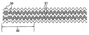
また、媒体10では、第1記録層12が形成される案内溝に、図6に示すような、トラッキング方向に対して直行方向に蛇行するウォブル形状にフォーマットされた案内溝(ウォブル溝)31を採用する。光ディスクなどでは一般的に、案内溝の円周方向の一部に、案内溝を構成する各トラックのアドレス情報を付与するために、アドレス付与部32を設ける。
Further, in the medium 10, a guide groove (wobble groove) 31 formatted in a wobble shape meandering in a direction perpendicular to the tracking direction as shown in FIG. 6 is formed in the guide groove in which the
従来から多用されているアドレス付与方法として、図5に示すような、プリビット33を形成する方法がある。この方法では、蛇行の無い通常形状の案内溝34が採用される。アドレス付与部32では案内溝34に代えて、各トラック毎に不規則な島状のプリビット33が形成される。しかし、この方法では、アドレス付与部32とこれ以外の領域とで溝の形状が大きく異なり、両領域の表面の散乱が大きく異なる。このため、アドレス付与部32の近傍で透過光の強度に乱れが生じ、第2記録層14への安定した記録及び再生がしにくい。
As an address assignment method that has been frequently used, there is a method of forming a pre-bit 33 as shown in FIG. In this method, a
そこで、本実施形態の媒体10の案内溝には、図6に示すように、一定の蛇行の繰返しを有する形状のウォブル溝31を採用することが望ましい。アドレス付与部32には、ウォブル溝31がそのまま形成され、かつ形状が部分的に不規則になっている。図6に示す例では、蛇行の繰り返しが位置35で位相が180°ずれている。溝形状を不規則にする方法は、これ以外にも、例えば、アドレス付与部32で蛇行の繰返しの周期を±10%以内でずらす方法などもある。何れにしても、ウォブル溝31を形成する場合、アドレス付与部32とそれ以外の溝形成部との溝の形状の違いは、プリビット33を形成する場合と比較して小さく、両領域の表面散乱の差も小さい。このため、アドレス付与部32の近傍でも、透過光の強度の乱れを抑制し、第2記録層14への安定した記録及び再生を行うことができる。
Therefore, as shown in FIG. 6, it is desirable to employ a
本実施形態の媒体10によれば、第1記録層12の記録層管理情報及び欠陥管理情報を格納したことにより、第2記録層14に対する記録又は再生を行う際に常にこれらの情報を確認し、安定した記録及び再生を行うことができる。また、第1記録層12の記録層管理情報及び欠陥管理情報が、第2記録層14のコントロール領域21にも格納されることにより、迅速な情報の確認と、これらの情報の消失に対するリスク分散とを図ることができる。更に、第1記録層12にウォブル溝31を形成したことにより、アドレス付与部32近傍の透過光強度の乱れを抑制し、安定したデータの記録及び再生を行うことができる。
According to the medium 10 of the present embodiment, since the recording layer management information and defect management information of the
本実施形態に係る媒体10の記録再生方法、記録方法、再生方法について説明する。先ず、第2記録層14に対して記録又は再生を行う際には、第2記録層14のコントロール領域21を確認する。この際に、第2記録層14の記録又は再生を行う対象エリア26に対して、第2記録層の上部に重なる第1記録層12のエリア27の記録状態が、既記録であるか未記録であるかを確認する。エリア27は、第2記録層14上に焦点を結ぶレーザ光25の第1記録層12上での拡がりを基準に、第2記録層14のトラック幅や、第1記録層12と第2記録層14とのディスク偏心ズレ量も考慮して設定する。次いで、確認を行った第1記録層12のエリア27の記録状態に基づいて、レーザ光の出力をそれぞれ所定の出力に適宜変更して、第2記録層14に対する記録又は再生を行う。例えば、第1記録層への記録によって、当該記録エリアの平均透過率が50%から61%に変化したとすると、これによって、第2記録層へのレーザ光25の透過量が変化する。この場合、第1記録層記録部に対するレーザ光出力を、未記録部に比べて0.82倍に設定すれば、同一のパワーが第2記録層に到達することになる。また、再生の場合は、第2記録層への到達光量よりも再生信号を生成する光検出器の受光量が変動しない方が好ましいので、ここで例示した条件の場合であれば、第1記録層記録部に対する再生レーザ光出力を、未記録部に比べて0.67倍に設定すれば、同一のパワーが光検出器に到達することになる。これらにより、第2記録層14に対する記録又は再生に際して、最適な透過光強度が得られるため、安定した記録及び再生を行うことができる。
A recording / reproducing method, a recording method, and a reproducing method of the medium 10 according to the present embodiment will be described. First, when recording or reproduction is performed on the
なお、記録時あるいは再生時のパワー条件については、第1記録層に記録されている場合と未記録の場合について、それぞれ規定値を媒体の所望のエリアにあらかじめ記録させておきそれを読み出して設定しても良いし、記録再生装置が媒体を識別してあらかじめその媒体に対して指定されていた規定値を読み出して、設定しても良い。 As for the power condition at the time of recording or reproduction, the specified value is recorded in advance in a desired area of the medium for both the case where the recording is performed on the first recording layer and the case where the recording is not performed. Alternatively, the recording / reproducing apparatus may identify a medium and read and set a specified value previously specified for the medium.
確認を行った第1記録層12のエリア27の記録状態が既記録部分と未記録部分とが混在している場合には、以下のように行う。記録を行う際には、第2記録層14に対して安定した記録を行うことが難しい。このため、基本的には、このエリアの第2記録層14に記録を行うことは避けることが好ましく、未記録となっている代替エリアに移って記録を行う。これにより、記録むらや記録欠損の発生を未然に防ぐことができる。
When the recorded state of the
一方、再生を行う際には、先ず、上述の混在状態となっているエリアの未記録部分に疑似記録を行ない、混在状態を解消する。次いで、レーザ光の出力を所定の既記録時の出力に変更して再生を行う。これにより、第2記録層14に均一な強度の透過光を照射して安定した再生を行ない、再生不良を抑制することができる。疑似記録には、予め規定されている疑似データを用いるとよい。
On the other hand, when performing reproduction, first, pseudo recording is performed on an unrecorded portion of the above-mentioned mixed state area to cancel the mixed state. Next, reproduction is performed by changing the output of the laser beam to a predetermined output at the time of recording. As a result, the
また、第2記録層14に対して記録又は再生を行う際に、第1記録層12の欠陥管理情報を確認することが望ましい。欠陥管理情報の確認を行ない、第2記録層14の記録しようとするエリアの上部に重なる第1記録層12のエリア27に欠陥が存在する場合には、例えば、代替エリアに移って記録を行うなどの手段を採ることができる。これにより、記録むらや記録欠損などの発生を抑制することができる。
Further, it is desirable to check the defect management information of the
本実施形態の媒体10の記録再生方法、記録方法、再生方法によれば、第2記録層14に対する記録又は再生を行う際に、記録層管理情報により第1記録層12のエリア27の記録状態を確認し、それぞれ透過光の強度が最適になるようにレーザ光の出力を変更する。また、エリア27が混在状態である場合には、代替エリアに移って記録し、或いは疑似記録を行った後に再生する。更に、欠陥管理情報により第1記録層12の欠陥位置を確認して、所定の手段を講じる。これらの方法により、従来問題となっていた記録むら、記録欠損、及び再生不良などの発生を抑制することができる。
According to the recording / reproducing method, the recording method, and the reproducing method of the medium 10 of the present embodiment, the recording state of the
図2は、本発明の第2の実施形態に係る光学的情報記録再生媒体の層構造を示す断面図である。上述において、案内溝が形成された剛性を有する基板11を用いた場合について説明したが、光学的情報記録再生媒体の層構造としては、同図に示す媒体40のようなものでもよい。媒体40は、高密度化を図るために、高い開口数(NA)を有する集光レンズ30等を採用し、焦点距離を短くした光学的情報記録再生媒体である。このため、レーザ光の入射面に薄厚のカバー層15を形成し、大きな厚みを有する基板11を、レーザ光の入射面とは反対側に形成した構成を有する。
FIG. 2 is a sectional view showing a layer structure of an optical information recording / reproducing medium according to the second embodiment of the present invention. In the above description, the case where the
即ち、媒体40は、第1の実施形態に係る媒体10において、レーザ光の入射側に基板11に代えて、膜厚0.1mm程度の薄厚のカバー層15が設けられ、第2記録層14の裏側に基板11が設けられていることを除いては、媒体10と同様の構成を有する。媒体40は、このような構成により、例えばDVD以上の高密度化を図ることができる。
That is, in the medium 10 according to the first embodiment, the medium 40 is provided with a
図3は、本発明の第3の実施形態に係る光学的情報記録再生媒体の層構造を示す断面図である。光学的情報記録再生媒体の層構造としては、同図に示す媒体41のようなものでもよい。媒体41は、図1に示した媒体10を両面構成としたものであり、2つの媒体10の第2記録層14を向かい合わせて、接着層16を介して張り合わせた構成を有する。このような構成により、更なる大容量化を図ることができる。なお、必要に応じて、張り合わせる媒体10の内の片方をダミー基板としてもよい。
FIG. 3 is a sectional view showing the layer structure of an optical information recording / reproducing medium according to the third embodiment of the present invention. The layer structure of the optical information recording / reproducing medium may be a medium 41 shown in FIG. The medium 41 has a double-sided configuration of the medium 10 shown in FIG. 1 and has a configuration in which the second recording layers 14 of the two
図4は、本発明の第4の実施形態に係る光学的情報記録再生媒体の層構造を示す断面図である。光学的情報記録再生媒体の層構造としては、同図に示す媒体42のようなものでもよい。媒体42は、図2に示した媒体40を両面構成としたものであり、基板11を共通として、2つの媒体40を基板11の両面に形成した構成を有している。このような構成により、更なる大容量化を図ることができる。
FIG. 4 is a cross-sectional view showing a layer structure of an optical information recording / reproducing medium according to the fourth embodiment of the present invention. The layer structure of the optical information recording / reproducing medium may be a medium 42 shown in FIG. The medium 42 has a double-sided configuration of the medium 40 shown in FIG. 2, and has a configuration in which the
また、上述においては、記録層に相変化記録膜を用いた光学的情報記録再生媒体について説明したが、第1から第4の実施形態の媒体は、例えば追記型のいわゆるレコーダブルメディア(R媒体)に適用することも可能である。この場合には、記録層として、使用するレーザ波長に対して一定の吸収を示す有機色素、又は、Sn、Bi、In、Te、Pbなどの低融点金属、又は、変形しやすいSi、Geなどの材料を含む薄膜が採用される。また、これらの有機色素や薄膜の上下に誘電体保護膜や反射膜を形成した構成も採用される。 In the above description, the optical information recording / reproducing medium using the phase change recording film as the recording layer has been described. However, the medium according to the first to fourth embodiments is, for example, a write-once type so-called recordable medium (R medium). ) Is also possible. In this case, as the recording layer, an organic dye exhibiting a certain absorption with respect to the laser wavelength to be used, a low melting point metal such as Sn, Bi, In, Te, Pb, or Si, Ge, which is easily deformed, etc. A thin film containing these materials is employed. In addition, a configuration in which a dielectric protective film and a reflective film are formed above and below these organic dyes and thin films is also employed.
図7は、本発明の一実施形態に係る光学的情報記録再生装置の構成を示したブロック図である。基本構成は、レーザ光の照射によって記録及び再生が可能な複数の記録層を有する光学的情報記録再生媒体と、データの記録又は再生を行う記録層にレーザ光を集光する光ヘッドと、記録再生回路と、該記録層の記録状態を示す情報を少なくとも含む記録層管理情報を再生するために用いる記録層管理情報・再生手段と、記録レーザ光出力の設定を変更するレーザ光パワー切替手段として機能する記録パワー設定手段および再生パワー設定手段と、疑似データ生成回路とを有することである。装置50は、外部のホストとデータを授受しつつ、光学的情報記録再生媒体に対して記録及び再生を行う装置である 。
FIG. 7 is a block diagram showing a configuration of an optical information recording / reproducing apparatus according to an embodiment of the present invention. The basic configuration is an optical information recording / reproducing medium having a plurality of recording layers that can be recorded and reproduced by laser light irradiation, an optical head that focuses laser light on a recording layer for recording or reproducing data, and a recording As a reproducing circuit, recording layer management information / reproducing means used for reproducing recording layer management information including at least information indicating the recording state of the recording layer, and laser light power switching means for changing the setting of the recording laser light output It has a recording power setting unit and a reproduction power setting unit that function, and a pseudo data generation circuit. The
装置50は、光学的情報記録再生媒体である光ディスク51、光ディスク51に対して光学的な操作を行う光ヘッド52、光ディスク51を支持して回転させるスピンドルモータ53、光ヘッド52及びスピンドルモータ53の制御などを行う回路群54、回路群54の全体の制御などを行うコントローラ110、及び外部のホストとのデータの授受を行うインターフェイス111を有する。
The
回路群54は、回転制御回路101、サーボ制御回路102、記録再生回路103、記録データ処理回路104、疑似データ生成回路105、記録パワー設定回路106、再生パワー設定回路107、再生データ処理回路108、及び記録層管理情報・再生回路109から成る。
The
光ディスク51は、第1〜第4の実施形態に示したような2層の記録層を有する光学的情報記録再生媒体である。光ヘッド52は、光ディスク51上にレーザ光を照射するレーザ光源と、再生の際に光ディスク51からの反射光を検出する光検知器を有する。光ヘッド52は、記録再生回路103からの駆動信号を用いてレーザ光源を発光させ、回転する光ディスク51上の所定の位置にレーザビームを集光させ、再生時には、光検知器により光ディスク51からの反射光を検出する。レーザ光源は、記録時には再生時よりも高い出力のレーザ光を照射する。スピンドルモータ53は、回転制御回路101から制御を受けて光ディスク51を所定の回転位置に回転させる。
The
回転制御回路101は、スピンドルモータ53の回転を制御する。サーボ制御回路102は、記録再生回路103からのサーボ誤差信号及びコントローラ110からの指令に基づき、光ヘッド52のフォーカス制御、トラッキング制御、及び位置制御を行う。
The
記録再生回路103は、再生時には光ヘッド52の光検出器が検出した信号を増幅し、再生データ信号、コントロール領域21に格納された記録層管理情報に関する信号、フォーカス・サーボ誤差信号、及びトラッキング・サーボ誤差信号などの信号を生成する。また、記録時には、記録データ処理回路104から受信した信号を光ヘッド52に供給する。
The recording / reproducing
記録データ処理回路104は、インターフェイス111から受信した記録データにエラー訂正符号を付加して、記録再生回路103に送信する。また、疑似記録を行う際には、疑似データ生成回路105から受信した疑似データを記録用のデータに加工し、記録再生回路103に送信する。
The recording
疑似データ生成回路105は、疑似記録を行う際に、疑似データの生成を行ない、記録データ処理回路104に送信する。記録パワー設定回路106は、記録に際して必要な場合に、コントローラ110からの指令に従って、レーザ光の出力を所定値に変更する。再生パワー設定回路107は、再生に際して必要な場合に、コントローラ110からの指令に従って、レーザ光の出力を所定値に変更する。
The pseudo data generation circuit 105 generates pseudo data when performing pseudo recording, and transmits the pseudo data to the recording
再生データ処理回路108は、記録再生回路103から受信した再生データ信号を復調して再生データとし、これにエラー訂正を行った後、インターフェイス111に送信する。記録層管理情報・再生回路109は、コントロール領域21の再生時に再生データ処理回路108から信号を受信し、コントロール領域21の記録状態に関するデータを生成し、コントローラ110に送信する。
The reproduction
コントローラ110は、これらの各回路、インターフェイス111等の制御を行う。インターフェイス111は、外部のホストとの間で、記録及び再生の指令データや、記録データを受信し、また、再生データを送信する。
The
装置50は、このような構成により、第1〜第4の実施形態の光学的情報記録再生媒体と同様の効果を有する光学的情報記録再生装置として形成することができる。
With such a configuration, the
次に、前述の光学的情報記録再生媒体及び装置を用いた、本発明の一実施形態に係る記録再生方法、記録方法、再生方法について説明する。相変化型の記録膜に記録及び再生を行うことを前提に説明を行う。光学的情報記録再生媒体である光ディスク51は、2層の記録層を有する構成で、光ヘッド52を用いて記録又は再生がなされる。光ディスク51の第1記録層12及び第2記録層14には、図1に示したように、コントロール領域21が設けられており、ここに、第1記録層12の記録状態に関する記録層管理情報が格納される。つまり、前述したように、コントロール領域21が記録管理領域として機能する。
Next, a recording / reproducing method, recording method, and reproducing method according to an embodiment of the present invention using the above-described optical information recording / reproducing medium and apparatus will be described. The description will be made on the assumption that recording and reproduction are performed on a phase change recording film. An
記録層管理情報が格納されるコントロール領域内での記録層管理情報の配置には制限はないが、例えば、レーザ入射側から見て、第1記録層の記録層管理情報配置位置の奥に重ねて、第2記録層の記録層管理情報を配置しても良く、あるいは、第1記録層の記録層管理情報配置位置の奥に重ならない位置に、第2記録層の記録層管理情報を配置しても良い。 There is no restriction on the arrangement of the recording layer management information in the control area in which the recording layer management information is stored. For example, when viewed from the laser incident side, the recording layer management information is placed behind the recording layer management information arrangement position. Thus, the recording layer management information of the second recording layer may be arranged, or the recording layer management information of the second recording layer is arranged at a position that does not overlap the recording layer management information arrangement position of the first recording layer. You may do it.
第1記録層の記録層管理情報配置位置の奥に重ならない位置に、第2記録層の記録層管理情報を配置した場合のほうが、第2記録層への記録再生に対して、第1記録層の記録状態に影響されないので、記録層管理情報の記録再生に当たっての信頼性は高くなる。 When the recording layer management information of the second recording layer is arranged at a position that does not overlap the recording layer management information arrangement position of the first recording layer, the first recording is performed with respect to the recording / reproducing on the second recording layer. Since it is not affected by the recording state of the layer, the reliability in recording / reproducing the recording layer management information is increased.
第1記録層には少なくとも第1記録層の記録層管理情報が記録されればよいが、第2記録層には少なくとも第1記録層の記録層管理情報が記録される必要があり、更には第2記録層の記録再生動作上は、第2記録層の記録層管理情報も記録されている方が好都合である。 The recording layer management information of at least the first recording layer may be recorded on the first recording layer, but at least the recording layer management information of the first recording layer needs to be recorded on the second recording layer. In the recording / reproducing operation of the second recording layer, it is advantageous that the recording layer management information of the second recording layer is also recorded.
各層の記録層管理情報は、各層に記録をおこなった際に更新するので、追記型の場合は、コントロール領域である記録管理領域を十分確保しておき、更新情報を追記すればよい。書き換え可能型の場合は、更新情報を追記してもよく、旧データを書き換えてもよい。 Since the recording layer management information of each layer is updated when recording is performed on each layer, in the case of the write-once type, a sufficient recording management area as a control area should be secured and the update information added. In the case of the rewritable type, update information may be added or old data may be rewritten.
次に記録層管理情報の更新手順について説明する。第1記録層に記録をおこなった場合には、例えば、記録に使用したアドレスのうち、開始アドレスと終了アドレス、使用したエリア番号をセットとして第1記録層ならびに第2記録層の記録管理領域に記録層管理情報として記録する。第2記録層に記録をおこなった場合には、例えば、記録に使用したアドレスのうち、開始アドレスと終了アドレス、使用したエリア番号をセットとして第2記録層の記録管理領域に記録層管理情報として記録する。位置情報あるいは時間情報からなる記録層管理情報を使用する場合も同様の操作をおこなう。 Next, a procedure for updating the recording layer management information will be described. When recording is performed on the first recording layer, for example, among the addresses used for recording, the start address and end address, and the used area number are set as a set in the recording management areas of the first recording layer and the second recording layer. Record as recording layer management information. When recording is performed on the second recording layer, for example, among the addresses used for recording, the start address and end address, and the used area number are set as recording layer management information in the recording management area of the second recording layer. Record. The same operation is performed when recording layer management information consisting of position information or time information is used.
ビットマップ形式で記録層管理情報を記録する場合は、第1記録層に記録をおこなった場合には、例えば、記録に使用したECCブロックに相当するビットマップ所望のビットを「1」に変更・更新して第1記録層ならびに第2記録層の記録管理領域に記録層管理情報として記録する。第2記録層に記録をおこなった場合には、例えば、同様に、記録に使用したECCブロックに相当するビットマップ所望のビットを「1」に変更・更新して第2記録層の記録管理領域に記録層管理情報として記録する。 When recording layer management information is recorded in the bitmap format, when recording is performed on the first recording layer, for example, the desired bit of the bitmap corresponding to the ECC block used for recording is changed to “1”. It is updated and recorded as recording layer management information in the recording management areas of the first recording layer and the second recording layer. When recording is performed on the second recording layer, for example, similarly, the desired bit of the bitmap corresponding to the ECC block used for recording is changed / updated to “1” to record management area of the second recording layer Is recorded as recording layer management information.
次に、欠陥管理情報を更新する場合の手順について説明する。第1記録層に記録・再生をおこなって記録再生に使用できない欠陥部が見つかった場合には、例えば、欠陥部を含むアドレスのうち、欠陥部開始アドレスと欠陥部終了アドレス、欠陥が存在するエリア番号をセットとして第1記録層ならびに第2記録層の記録管理領域に欠陥管理情報として記録する。第2記録層に記録・再生をおこなって記録再生に使用できない欠陥部が見つかった場合には、例えば、欠陥部を含むアドレスのうち、欠陥部開始アドレスと欠陥部終了アドレス、欠陥が存在するエリア番号をセットとして第2記録層の記録管理領域に欠陥管理情報として記録する。位置情報あるいは時間情報からなる欠陥管理情報を使用する場合も同様の操作をおこなう。 Next, a procedure for updating defect management information will be described. When a defective part that cannot be used for recording / reproduction is found on the first recording layer, for example, among the addresses including the defective part, the defective part start address, the defective part end address, and the area where the defect exists The numbers are recorded as defect management information in the recording management areas of the first recording layer and the second recording layer as a set. In the case where a defect portion that cannot be used for recording / reproduction is found on the second recording layer, for example, among the addresses including the defect portion, the defect portion start address, the defect portion end address, and the area where the defect exists Numbers are recorded as defect management information in the recording management area of the second recording layer as a set. The same operation is performed when defect management information including position information or time information is used.
ビットマップ形式で欠陥管理情報を記録する場合は、第1記録層に記録・再生をおこなって記録再生に使用できない欠陥部が見つかった場合には、例えば、欠陥が存在するECCブロックに相当するビットマップの所望ビットを「1」に変更・更新して第1記録層ならびに第2記録層の記録管理領域に欠陥管理情報として記録する。第2記録層に記録・再生をおこなって記録再生に使用できない欠陥部が見つかった場合には、例えば、同様に、欠陥が存在するECCブロックに相当するビットマップ所望のビットを「1」に変更・更新して第2記録層の記録管理領域に欠陥管理情報として記録する。 When the defect management information is recorded in the bitmap format, when a defective portion that cannot be used for recording / reproduction is found on the first recording layer, for example, a bit corresponding to an ECC block in which a defect exists The desired bit of the map is changed / updated to “1” and recorded as defect management information in the recording management areas of the first recording layer and the second recording layer. If a defective part that cannot be used for recording / reproduction is found in the second recording layer, for example, the desired bit of the bitmap corresponding to the ECC block in which the defect exists is similarly changed to “1”. Update and record as defect management information in the recording management area of the second recording layer.
前述のように、光ディスク51の各トラックには、所定のアドレス付与方法によりアドレスが割り当てられている。このため、アドレスが確認できれば、各トラックの光ディスク上での半径が確定できる。複数の記録層を重ね合わせて成る媒体では、各記録層同士の重ね合わせは大変精度良く行われるので、各記録層のディスク偏心ズレ量は大変小さい。よって、第2記録層14のあるアドレスのトラックの半径と、第1記録層12における、対応するアドレスのトラックの半径もほぼ同じである。このため、第2記録層14の所定のトラックを特定した際に、装置50は、アドレスを介して第1記録層12の対応する位置に存在するトラックを特定し、記録層管理情報を確認することにより、このトラックの記録状態を確認することが可能である。
As described above, each track of the
記録又は再生時には、先ず、コントローラ110の指令により、第2記録層14の記録を行うトラックのアドレスを確定する。次に、第2記録層14のコントロール領域21を確認し、第2記録層14の記録しようとするエリアの上部に重なる第1記録層12のエリア27に含まれるトラックの記録状態が、既記録であるか未記録であるかを確認する。次いで、確認に基づいて、レーザ光の出力をそれぞれ所定の出力に適宜変更して、第2記録層14に対する記録又は再生を行う。これにより、第2記録層14に対する記録又は再生に際して、最適な透過光強度が得られるため、安定した記録及び再生を行うことができる。この場合に必要な補正条件は、光ディスク51の構成に応じて予め決定できるので、これを予め第2記録層14のコントロール領域21に記録してもよく、また装置50に記憶してもよい。
At the time of recording or reproduction, first, the address of the track on which the recording on the
また、確認を行ったエリア27の記録状態が、既記録部分と未記録部分とが混在している場合には、以下のように行う。記録を行う際には未記録部分である代替エリアに移って記録を行う。これにより、記録むらの発生を未然に防ぐことができる。一方、再生を行う際には、先ず、上述の混在しているエリアの未記録部分に疑似記録を行ない、混在状態を解消する。次いで、レーザ光を所定の出力に変更して再生を行う。これにより、第2記録層14に均一な強度の透過光を照射して安定した再生を行ない、従来問題となっていた再生不良を抑制することができる。疑似記録には、疑似データ生成回路105に予め記録させてある特定のパターン信号を用いるとよい。
Further, when the recorded state of the confirmed
また、別の記録方法として、先ず、上述の混在エリアの未記録部分に疑似記録を行ない、混在状態を解消する。次いで、レーザ光を所定の出力に変更して記録をおこなう。これにより、第2記録層14に均一な強度の透過光を照射して安定した記録を行うことができ、従来問題となっていた記録むら、記録欠損を抑制することができる。疑似記録には、前述した再生方法と同様に、疑似データ生成回路105に予め記録させてある特定のパターン信号を用いるとよい。
As another recording method, first, pseudo recording is performed on the unrecorded portion of the mixed area to eliminate the mixed state. Next, the laser beam is changed to a predetermined output and recording is performed. Accordingly, it is possible to perform stable recording by irradiating the
本発明の有効性を確認するために、以下に実施例1〜16として示す媒体の製造及び試験を行った。実施例1〜16は、それぞれ第1〜第4の実施形態の光学的情報記録再生媒体、及び実施形態の光学的情報記録再生装置の具体例であり、かつ種々の変形を伴う変形例である。実施例1〜6、実施例7〜11、実施例12〜16は、それぞれ同一の記録再生媒体及び記録再生装置を使用する。
実施例1
図8は本実施例の光学的情報記録再生媒体の構成を示す断面図である。媒体44は、表面に記録膜が形成された2つの基板を対向させて、所定の厚さを有する紫外線硬化樹脂を介して貼り合わせた構成を有する。
In order to confirm the effectiveness of the present invention, the production and testing of media shown as Examples 1 to 16 below were performed. Examples 1 to 16 are specific examples of the optical information recording / reproducing media of the first to fourth embodiments and the optical information recording / reproducing apparatus of the embodiments, respectively, and are modifications with various modifications. . Examples 1-6, Examples 7-11, and Examples 12-16 use the same recording / reproducing medium and recording / reproducing apparatus, respectively.
Example 1
FIG. 8 is a cross-sectional view showing the configuration of the optical information recording / reproducing medium of this embodiment. The medium 44 has a configuration in which two substrates having a recording film formed on the surface are opposed to each other and are bonded via an ultraviolet curable resin having a predetermined thickness.
即ち、第1基板17として、外径が120mm、内径が15mm、基板厚さが0.6mmのポリカーボネート樹脂基板を用いた。第1基板17には、図6に示したウォブル溝31が、予めマスタリングで形成されているものを使った。ウォブル溝31の形状は、深さが60nm、トラックピッチが0.74μmである。ウォブル溝31は螺旋状で、かつ第1基板17の内周から外周にかけて、線速3.9m/secで回転した際に、ウォブル周波数が700kHzとなるように形成した。第1基板17の半径22mm〜24mmをコントロール領域21とし、その外側の半径24mm〜58mmをデータ記録領域22とした。コントロール領域21と、データ記録領域22の各トラックには前述の方法に従って、予め指定のアドレスを割り当てた。
That is, a polycarbonate resin substrate having an outer diameter of 120 mm, an inner diameter of 15 mm, and a substrate thickness of 0.6 mm was used as the
第1記録層12として、スパッタ法により第1基板17上に順次に、ZnS−SiO2から成る下部保護膜12A、GeSbTeから成る相変化記録膜12B、及びZnS−SiO2から成る上部保護膜12Cを形成した。
The
第2基板18として、外径が120mm、内径が15mm、基板厚さが0.6mmのポリカーボネート樹脂基板を用いた。第2基板18の表面には、マスタリングで作製したウォブル溝31が予め形成され、かつ第1基板17の表面に形成されたウォブル溝31とは螺旋形状が逆向きに形成されている。第2基板18のウォブル溝31の、深さ、トラックピッチ、ウォブル周波数、並びに、コントロール領域21及びデータ記録領域22の構成等は、第1基板17の場合と同様とした。
As the
第2記録層14として、スパッタ法により第2基板18上に順次に、Al−Tiから成る反射膜14D、ZnS−SiO2から成る上部保護膜14C、GeSbTeから成る相変化記録膜14B、及びZnS−SiO2から成る下部保護膜14Aを形成した。
As the
次に、スペーサ層13として、スピンコート法により第1記録層12上に、厚さが40μmに成るように紫外線硬化樹脂を展開する。続いて、第1記録層12と第2記録層14とを対向させ、第1基板17及び第2基板18の偏心を抑えて、これらを貼り合わせた後、紫外線硬化樹脂を紫外線照射により硬化させた。
Next, as the
続いて、第1記録層12及び第2記録層14の記録を行うデータ記録領域の全面に対して、初期化装置を用いて初期化を行った。即ち未記録に相当する初期状態である結晶状態にすることにより、媒体44として形成した。第1の実施形態に係る媒体10と同様に、第1記録層12の記録層管理情報及び欠陥管理情報を、第1記録層12及び第2記録層14に格納するようにした。
Subsequently, the entire surface of the data recording area where the
本実施例の媒体44について光学特性を測定した。波長650nmのレーザ光を第1基板17側から照射した場合、第1記録層12は単独で、未記録時の結晶状態では、反射率が10%、透過率が50%であり、既記録時の非晶質状態では、反射率が2.5%、透過率が72%であった。また、第2記録層14は単独で、未記録時の結晶状態での反射率は12%、既記録時の非晶質状態での反射率は30%であった。
The optical characteristics of the medium 44 of this example were measured. When a laser beam having a wavelength of 650 nm is irradiated from the
また、同様の条件で媒体44は、第2記録層14が未記録で、第1記録層12が未記録の際には、第2記録層14からの反射率は3%であるが、第1記録層12が既記録になると、第2記録層14からの反射率は約4.5%になった。また、第2記録層14が既記録で、第1記録層12が未記録の際には、第2記録層14からの反射率は7.5%であるが、第1記録層12が既記録になると、第2記録層14からの反射率は約11%になった。
Under the same conditions, when the
相変化記録媒体用の光ヘッドを使い、媒体44への記録を試みた。光ヘッドのレーザ波長は650nmで、集光レンズのNAは0.65である。記録には、図7を参照して説明した、実施形態に係る装置50を使用した。
Recording on the medium 44 was attempted using an optical head for a phase change recording medium. The laser wavelength of the optical head is 650 nm, and the NA of the condenser lens is 0.65. For recording, the
先ず、第1記録層12の半径30mm〜32mmのデータ記録領域22にデータを記録した。この際に、前述の手順に従い、第2記録層14のコントロール領域21には、第1記録層12の半径30mm〜32mmに割り当てられているアドレス(69680hex番地〜7E2DFhex番地)が既記録であることを示す情報が記録された。
First, data was recorded in the
続いて、ホストから、第2記録層14のデータ記録領域22の半径30.5mm〜31.2mmに記録を行う旨の指令を送信した。装置50は、前述の手順に従い、先ず第2記録層14のコントロール領域21の再生を行ない、第1記録層12の半径30〜32mmが既記録であることを記録層管理情報・再生回路109が認識し、コントローラ110にその旨を示すデータを送信した。次に、コントローラ110の指令により、第2記録層14の半径30.5mmの位置に光ヘッド52のレーザ光の焦点を移動させた。続いて、コントローラ110は、レーザ光の出力(記録パワー)を初期値である12mWから10mWに減少させる指令を、記録パワー設定回路106に送信した。このような一連の動作等により、所望エリアである半径30.5mm〜31.2mmに対して良好な記録が行なわれた。
Subsequently, a command for recording to a radius of 30.5 mm to 31.2 mm of the
上述により、第1記録層12が既記録である場合に、レーザ光の出力を減少させることによって、第2記録層14に対して良好な記録が行われることが確認できた。
実施例2
実施例1の媒体44、及び実施形態に係る装置50を使用し、第2記録層14からの再生を試みた。
From the above, it was confirmed that when the
Example 2
Using the medium 44 of Example 1 and the
先ず、第2記録層14の半径30mm〜32mmのデータ記録領域22にデータを記録した。次に、第1記録層12の半径30.5mm〜31.5mmのデータ記録領域22にデータを記録した。この際に、前述の手順に従い、第2記録層14のコントロール領域21には、第1記録層12の半径30.5mm〜31.5mmに割り当てられているアドレス(6ED90hex番地〜79BDFhex番地)が既記録である旨を示す情報が記録された。
First, data was recorded in the
続いて、ホストから、第2記録層14のデータ記録領域22の半径31mmの位置を再生する旨の指令を送信した。装置50は、前述の手順に従い、先ず、第2記録層14のコントロール領域21の再生を行ない、第1記録層12の半径30.5〜31.5mmが既記録であることを記録層管理情報・再生回路109が認識し、コントローラ110にその旨を示すデータを送信した。次に、コントローラ110の指令により、第2記録層14の半径30.5mmの位置に光ヘッド52のレーザ光の焦点を移動させた。続いて、コントローラ110は、レーザ光の出力(再生パワー)を初期値である1.2mWから1.0mWに減少させる指令を再生パワー設定回路107に送信した。このような一連の動作等により、所望エリアである半径31mmから良好な再生信号が得られた。
Subsequently, a command for reproducing the position of the
上述により、第1記録層12が既記録である場合に、レーザ光の出力を減少させることによって、第2記録層14から良好な再生が行われることが確認できた。
実施例3
実施例1の媒体44、及び実施形態に係る装置50を使用して、第2記録層14への記録を試みた。
From the above, it was confirmed that when the
Example 3
Using the medium 44 of Example 1 and the
先ず、第1記録層12の半径30mm〜32mmのデータ記録領域22にデータを記録した。この際に、前述の手順に従い、第1記録層12の内周に形成されたコントロール領域21には、第1記録層12の半径30mm〜32mmに割り当てられているアドレス(69680hex番地〜7E2DFhex番地)が既記録であることを示す情報が記録された。
First, data was recorded in the
続いて、ホストから、第2記録層14のデータ記録領域22の半径31.8mm〜32.2mmに記録を行う旨の指令を送信した。装置50は、前述の手順に従い、先ず、第2記録層14のコントロール領域21の再生を行ない、第1記録層12の半径30mm〜32mmが既記録であることを記録層管理情報・再生回路109が認識し、コントローラ110にその旨を示すデータを送信した。
Subsequently, a command for recording to a radius of 31.8 mm to 32.2 mm of the
次に、コントローラ110は、第1記録層12の半径31.8mm〜32.0mmが既記録であるため、即ち第2記録層14の上述半径のエリアに記録を行う場合に記録対象部分26の上部に重なる第1記録層のエリア27が混在となるため、ここへの記録を中止し、記録位置を代替エリアである半径34.8mmの位置に移動した。次いで再び、第2記録層14のコントロール領域21の再生を行ない、第1記録層12の半径34.5mm〜35.5mmが未記録であることを記録層管理情報・再生回路109が認識し、コントローラ110にその旨を示すデータを送信した。続いて、コントローラ110は、レーザ光の出力(記録パワー)を初期値である12mWに設定させる指令を記録パワー設定回路106に送信した。このような一連の動作等により、代替エリアである半径34.8mm〜35.2mmに対して良好な記録が行なわれた。
Next, the
上述により、第1記録層12のエリア27が混在状態となる場合に、代替エリアに移動して記録を行うことによって、第2記録層14に対して良好な記録が行われることが確認できた。
実施例4
実施例1の媒体44、及び実施形態に係る装置50を使用して、第2記録層14からの再生を試みた。
As described above, when the
Example 4
Using the medium 44 of Example 1 and the
先ず、第2記録層14の半径30mm〜32mmのデータ記録領域22にデータを記録した。次に、第1記録層12の半径30.5mm〜31.5mmのデータ記録領域22にデータを記録した。この際に、前述の手順に従い、第2記録層14のコントロール領域21には、第1記録層12の半径30.5mm〜31.5mmに割り当てられているアドレス(6ED90hex番地〜79BDFhex番地)が既記録であることを示す情報が記録された。
First, data was recorded in the
続いて、ホストから、第2記録層14のデータ記録領域22の半径30.3mmから30.7mmを再生する旨の指令を送信した。装置50は、前述の手順に従い、先ず、第2記録層14のコントロール領域21の再生を行ない、第1記録層12の半径30.5〜31.5mmが既記録であることを記録層管理情報・再生回路109が認識し、コントローラ110にその旨を示すデータを送信した。次に、コントローラ110の指令により、第1記録層12の半径30.0mmの位置に光ヘッド52のレーザ光の焦点を移動させた後、半径30.0mm〜30.5mmに対して疑似データの記録を行った。疑似データの記録には、疑似データ生成回路105から記録データ処理回路104に送信されたデータが用いられた。
Subsequently, a command for reproducing the radius 30.3 mm to 30.7 mm of the
次に、コントローラ110の指令により、光ヘッド52のレーザ光の焦点を第2記録層14に移動させた。続いて、コントローラ110は、レーザ光の出力(再生パワー)を初期値である1.2mWから1.0mWに減少させる指令を再生パワー設定回路107に送信した。これらの一連の動作等により、所望のエリアである半径30.3mmから30.7mmまで良好な再生信号が得られた。
Next, the focal point of the laser beam of the
上述により、第1記録層12のエリア27が混在である場合に、未記録部分に疑似データの記録を行うことによって、第2記録層14から良好な再生が行われることが確認できた。
実施例5
実施例1の媒体44、及び実施形態に係る装置50を使用して、第2記録層14への記録を試みた。
As described above, when the
Example 5
Using the medium 44 of Example 1 and the
先ず、第2記録層14の半径30mm〜31mmのデータ記録領域22にデータを記録した。次に、第1記録層12の半径30.5mm〜31.5mmのデータ記録領域22にデータを記録した。この際に、前述の手順に従い、第2記録層14のコントロール領域21には、第1記録層12の半径30.5mm〜31.5mmに割り当てられているアドレス(6ED90hex番地〜79BDFhex番地)が既記録であることを示す情報が記録された。
First, data was recorded in the
続いて、ホストから、第2記録層14のデータ記録領域22の半径31mmから32mmの位置を記録する旨の指令を送信した。装置50は、前述の手順に従い、先ず、第2記録層14のコントロール領域21の再生を行ない、第1記録層12の半径30.5〜31.5mmが既記録であることを記録層管理情報・再生回路109が認識し、コントローラ110にその旨を示すデータを送信した。次に、コントローラ110の指令により、第1記録層12の半径31.5mmの位置に光ヘッド52のレーザ光の焦点を移動させた後、半径31.5mm〜32.0mmに対して疑似データの記録を行った。疑似データの記録には、疑似データ生成回路105から記録データ処理回路104に送信されたデータが用いられた。
Subsequently, a command to record the position of the
次に、コントローラ110の指令により、光ヘッド52のレーザ光の焦点を第2記録層14に移動させた。続いて、コントローラ110は、レーザ光の出力(記録パワー)を初期値である12mWから10mWに減少させる指令を記録パワー設定回路106に送信した。これらの一連の動作等により、所望エリアである半径31.0mmから32.0mmにかけて良好な記録がおこなわれた。
Next, the focal point of the laser beam of the
上述により、第1記録層12のエリア27が混在である場合に、未記録部分に疑似データの記録を行うことによって、第2記録層14に良好な記録が行われることが確認できた。
実施例6
実施例1の媒体44、及び実施形態に係る装置50を使用して、第1記録層12に欠陥を有するエリアが存在する場合の記録再生動作を試みた。
As described above, when the
Example 6
Using the medium 44 of Example 1 and the
先ず、第1記録層12の半径30mm〜32mmのデータ記録領域22にデータを記録した。この後、第1記録層12の半径30mm〜32mmを再生したが、半径31.6mm〜31.7mmのエリアでは、データの再生が困難であった。即ち、半径31.6mm〜31.7mmのエリアは欠陥エリアである。このため、第2記録層14のコントロール領域21には、第1記録層12の半径30mm〜32.0mmに割り当てられているアドレス(69680hex番地〜7E2DFhex番地)が既記録であることを示す情報、及び第1記録層12の半径31.6mm〜31.7mmのエリアが欠陥エリアであることを示す欠陥領域情報が記録された。
First, data was recorded in the
続いて、ホストから、第2記録層14のデータ記録領域22の半径31.5mm〜31.8mmに記録を行う旨の指令を送信した。装置50は、前述の手順に従い、先ず、第2記録層14のコントロール領域21の再生を行ない、第1記録層12の半径30〜32mmが既記録であること、及び第1記録層12の半径31.6mm〜31.7mmが欠陥エリアであることを記録層管理情報・再生回路109が認識し、コントローラ110にその旨を示すデータを送信した。
Subsequently, a command for recording to a radius of 31.5 mm to 31.8 mm of the
次に、コントローラ110は、第1記録層12の半径31.6mm〜31.7mmが欠陥エリアであることから、このエリア近傍の第2記録層14への記録を中止し、記録位置を代替エリアである半径34.5mmの位置に移動した。次いで再び、第2記録層14のコントロール領域21の再生を行ない、第1記録層12の半径34.2mm〜35.1mmが未記録であることを記録層管理情報・再生回路109が認識し、コントローラ110にその旨を示すデータを送信した。続いて、コントローラ110は、レーザ光の出力(記録パワー)を初期値である12mWに設定させる指令を記録パワー設定回路106に送信した。このような一連の動作等により、代替エリアである半径34.5mm〜34.8mmに対して良好な記録が行なわれた。
Next, since the radius of 31.6 mm to 31.7 mm of the
上述により、第1記録層12に欠陥が存在する場合に、代替エリアに移動することによって、第2記録層14に対して良好な記録が行われることが確認できた。
実施例7
図9は本実施例の光学的情報記録再生媒体の構成を示す断面図である。本実施例の光学的情報記録再生媒体は、追記型の媒体45であって、実施例1の媒体44とは、第1記録膜12及び第2記録膜14の構成が異なることを除いて、媒体44と同様の構成を有する。
From the above, it was confirmed that when the
Example 7
FIG. 9 is a cross-sectional view showing the structure of the optical information recording / reproducing medium of this embodiment. The optical information recording / reproducing medium of the present embodiment is a write-
即ち、第1記録層12として、スパッタ法により基板11上に順次に、ZnS−SiO2から成る下部保護膜12A、TeSn系合金から成る追記型記録膜122、及びZnS−SiO2から成る上部保護膜12Cを形成した。第2記録層14として、スパッタ法により第2基板18上に順次に、Al−Tiから成る反射膜14D、ZnS−SiO2から成る上部保護膜14C、TeSn系合金から成る追記型記録膜142、及びZnS−SiO2から成る下部保護膜14Aを形成した。
That is, the
本実施例の媒体について光学特性を測定した。波長650nmのレーザ光を第1基板17側から照射した場合、第1記録層12は単独で、未記録時には、反射率が6%、透過率が70%であり、既記録時には、追記型の記録マークが形成されたエリアにおいて、平均反射率が8%、平均透過率が60%であった。また、第2記録層14は単独で、未記録時の反射率は16%、既記録時の平均反射率は21%であった。
The optical characteristics of the medium of this example were measured. When a laser beam having a wavelength of 650 nm is irradiated from the
また、同様の条件で本実施例の媒体は、第2記録層14が未記録で、第1記録層12が未記録時の際には、第2記録層14からの反射率は7.8%であるが、第1記録層12が既記録になると、第2記録層14からの反射率は約5.85%になった。また、第2記録層14が既記録で、第1記録層12が未記録の際には、第2記録層14からの反射率は10.3%であるが、第1記録層12が既記録になると、第2記録層14からの反射率は約7.6%になった。
Further, under the same conditions, in the medium of this example, when the
次に、追記型記録媒体用の光ヘッドを使い、本実施例の媒体への記録を試みた。光ヘッドのレーザ波長は650nmで、集光レンズのNAは0.65である。記録には、図7を参照して説明した、実施形態に係る装置50を使用した。
Next, recording on the medium of this example was attempted using an optical head for a write-once recording medium. The laser wavelength of the optical head is 650 nm, and the NA of the condenser lens is 0.65. For recording, the
先ず、第1記録層12の半径30mm〜32mmのデータ記録領域22にデータを記録した。この際に、前述の手順に従い、第2記録層12のコントロール領域21には、第1記録層12の半径30mm〜32mmに割り当てられているアドレス(69680hex番地〜7E2DFhex番地)が既記録であることを示す情報が記録された。
First, data was recorded in the
続いて、ホストから、第2記録層14のデータ記録領域22の半径30.5mm〜31.2mmに記録を行う旨の指令を送信した。装置50は、前述の手順に従い、先ず第2記録層14のコントロール領域21の再生を行ない、第1記録層12の半径30〜32mmが既記録であることを記録層管理情報・再生回路109が認識し、コントローラ110にその旨を示すデータを送信した。次に、コントローラ110の指令により、第2記録層14の半径30.5mmの位置に光ヘッド52のレーザ光の焦点を移動させた。続いて、コントローラ110は、レーザ光の出力(記録パワー)を初期値である6mWから7mWに増加させる指令を記録パワー設定回路106に送信した。このような一連の動作等により、所望エリアである半径30.5mm〜31.2mmに対して良好な記録が行なわれた。
Subsequently, a command for recording to a radius of 30.5 mm to 31.2 mm of the
上述により、追記型の媒体において、第1記録層12が既記録である場合に、レーザ光の出力を増加させることによって、第2記録層14に対して良好な記録が行われることが確認できた。
実施例8
実施例7の媒体、及び実施形態に係る装置50を使用し、第2記録層14からの再生を試みた。
As described above, in the write-once medium, when the
Example 8
Using the medium of Example 7 and the
先ず、第2記録層14の半径30mm〜32mmのデータ記録領域22にデータを記録した。次に、第1記録層12の半径30.5mm〜31.5mmのデータ記録領域22にデータを記録した。この際に、前述の手順に従い、第2記録層14のコントロール領域21には、第1記録層12の半径30.5mm〜31.5mmに割り当てられているアドレス(6ED90hex番地〜79BDFhex番地)が既記録であることを示す情報が記録された。
First, data was recorded in the
続いて、ホストから、第2記録層14のデータ記録領域22の半径31mmの位置を再生する旨の指令を送信した。装置50は、前述の手順に従い、先ず、第2記録層14のコントロール領域21の再生を行ない、第1記録層12の半径30.5〜31.5mmが既記録であることを記録層管理情報・再生回路109が認識し、コントローラ110にその旨を示すデータを送信した。次に、コントローラ110の指令により、第2記録層14の半径30.5mmの位置に光ヘッド52のレーザ光の焦点を移動させた。続いて、コントローラ110は、レーザ光の出力(再生パワー)を初期値である0.6mWから0.7mWに増加させる指令を再生パワー設定回路107に送信した。このような一連の動作等により、所望エリアである半径31mmから良好な再生信号が得られた。
Subsequently, a command for reproducing the position of the
上述により、追記型の媒体において、第1記録層12が既記録である場合に、レーザ光の出力を増加させることによって、第2記録層14から良好な再生が行われることが確認できた。
実施例9
実施例7の媒体、及び実施形態に係る装置50を使用して、第2記録層14への記録を試みた。
As described above, it was confirmed that in the write-once medium, when the
Example 9
Recording on the
先ず、第1記録層12の半径30mm〜32mmのデータ記録領域22にデータを記録した。この際に、前述の手順に従い、第2記録層12のコントロール領域21には、第1記録層12の半径30mm〜32mmに割り当てられているアドレス(69680hex番地〜7E2DFhex番地)が既記録であることを示す情報が記録された。
First, data was recorded in the
続いて、ホストから、第2記録層14のデータ記録領域22の半径31.8mm〜32.2mmに記録を行う旨の指令を送信した。装置50は、前述の手順に従い、先ず、第2記録層14のコントロール領域21の再生を行ない、第1記録層12の半径30mm〜32mmが既記録であることを記録層管理情報・再生回路109が認識し、コントローラ110にその旨を示すデータを送信した。次に、コントローラ110は、第1記録層12の半径31.8mm〜32.0mmが既記録であるため、即ち第2記録層14の上述の半径エリアに記録を行う場合に記録対象部分26のエリア27が混在状態であるため、このエリア近傍の第2記録層14への記録を中止し、記録位置を代替エリアである半径34.8mmの位置に移動した。
Subsequently, a command for recording to a radius of 31.8 mm to 32.2 mm of the
次いで再び、第2記録層14のコントロール領域21の再生を行ない、第1記録層12の半径34.5mm〜35.5mmが未記録であることを記録層管理情報・再生回路109が認識し、コントローラ110にその旨を示すデータを送信した。続いて、コントローラ110は、レーザ光の出力(記録パワー)を初期値である6mWに設定させる指令データを記録パワー設定回路に出力した。このような一連の動作等により、代替エリアである半径34.8mm〜35.2mmに対して良好な記録が行なわれた。
Next, the
上述により、追記型の媒体において、第1記録層12のエリア27が混在である場合に、代替エリアに移動して記録を行うことによって、第2記録層14に対して良好な記録が行われることが確認できた。
実施例10
実施例7の媒体、及び実施形態に係る装置50を使用して、第2記録層14からの再生を試みた。
As described above, in the write-once type medium, when the
Example 10
Using the medium of Example 7 and the
先ず、第2記録層14の半径30mm〜32mmのデータ記録領域22にデータを記録した。次に、第1記録層12の半径30.5mm〜31.5mmのデータ記録領域22にデータを記録した。この際に、前述の手順に従って、第2記録層14のコントロール領域21には、第1記録層12の半径30.5mm〜31.5mmに割り当てられているアドレス(6ED90hex番地〜79BDFhex番地)が既記録であることを示す情報が記録された。
First, data was recorded in the
続いて、ホストから第2記録層14のデータ記録領域22の半径30.3mmから30.8mmの再生する旨の指令を送信した。装置50は、前述の手順に従い、先ず、第2記録層14のコントロール領域21の再生を行ない、第1記録層12の半径30.5〜31.5mmが既記録であることを記録層管理情報・再生回路109が認識し、コントローラ110にその旨を示すデータを送信した。次に、コントローラ110の指令により、第1記録層12の半径30.0mmの位置に光ヘッド52のレーザ光の焦点を移動させた後、半径30.0mm〜30.5mmに対して疑似データの記録を行った。疑似データの記録には、疑似データ生成回路105から記録データ処理回路104に送信されたデータが用いられた。
Subsequently, a command to reproduce from the radius 30.3 mm to 30.8 mm of the
次に、コントローラ110の指令により、第2記録層14に光ヘッド52のレーザ光の焦点を移動させた。続いて、コントローラ110は、レーザ光の出力(再生パワー)を初期値である0.6mWから0.7mWに増加させる指令を再生パワー設定回路107に送信した。これらの一連の動作等により、所望エリアである半径30.3mmから30.8mmまで良好な再生信号が得られた。
Next, the focal point of the laser beam of the
上述により、追記型の媒体において、第1記録層12のエリア27が混在である場合に、未記録部分に疑似データの記録を行うことによって、第2記録層14から良好な再生が行われることが確認できた。
実施例11
実施例7の媒体、及び実施形態に係る装置50を使用して、第2記録層14への記録を試みた。
As described above, in the write-once medium, when the
Example 11
Recording on the
先ず、第2記録層14の半径30.0mm〜31.0mmのデータ記録領域22にデータを記録した。次に、第1記録層12の半径30.5mm〜31.5mmのデータ記録領域22にデータを記録した。この際に、前述の手順に従って、第2記録層14のコントロール領域21には、第1記録層12の半径30.5mm〜31.5mmに割り当てられているアドレス(6ED90hex番地〜79BDFhex番地)が既記録であることを示す情報が記録された。
First, data was recorded on the
続いて、ホストから第2記録層14のデータ記録領域22の半径31.0mmから32.0mmの位置に記録をおこなう旨の指令を送信した。装置50は、前述の手順に従い、先ず、第2記録層14のコントロール領域21の再生を行ない、第1記録層12の半径30.5〜31.5mmが既記録であることを記録層管理情報・再生回路109が認識し、コントローラ110にその旨を示すデータを送信した。次に、コントローラ110の指令により、第1記録層12の半径31.5mmの位置に光ヘッド52のレーザ光の焦点を移動させた後、半径31.5mm〜32.0mmに対して疑似データの記録を行った。疑似データの記録には、疑似データ生成回路105から記録データ処理回路104に送信されたデータが用いられた。
Subsequently, a command for recording at a position of radius 31.0 mm to 32.0 mm in the
次に、コントローラ110の指令により、第2記録層14に光ヘッド52のレーザ光の焦点を移動させた。続いて、コントローラ110は、レーザ光の出力(記録パワー)を初期値である6mWから7mWに増加させる指令を記録パワー設定回路106に送信した。これらの一連の動作等により、所望エリアである半径31.0mmから32.0mmにかけて良好な記録が実行された。
Next, the focal point of the laser beam of the
上述により、追記型の媒体において、第1記録層12のエリア27が混在である場合に、未記録部分に疑似データの記録を行うことによって、第2記録層14から良好な記録が行われることが確認できた。
実施例12
本実施例の光学的情報記録再生媒体は、図2を参照して説明した、第2の実施形態に係る光学的情報記録再生媒体の具体例である。即ち、基板11として、外径が120mm、内径が15mm、基板厚さが0.6mmのポリカーボネート樹脂基板を用いた。基板11には、図6に示したウォブル溝31が、予めマスタリングで形成されているものを使った。ウォブル溝31の形状は、深さが35nm、トラックピッチが0.30μmである。ウォブル溝31は螺旋状で、かつ基板11の内周から外周にかけて、線速5.0m/secで回転した際に、ウォブル周波数が800kHzとなるように形成した。基板11の半径22mm〜24mmをコントロール領域21とし、その外側の半径24mm〜58mmをデータ記録領域22とした。コントロール領域21と、データ記録領域22には前述の所定の方法により、ウォブル溝31のトラック毎に予め指定のアドレスを割り当てた。
As described above, in the write-once medium, when the
Example 12
The optical information recording / reproducing medium of the present example is a specific example of the optical information recording / reproducing medium according to the second embodiment described with reference to FIG. That is, as the
第2記録層14として、スパッタ法により基板11上に順次に、Al−Tiから成る反射膜14D、ZnS−SiO2から成る上部保護膜14C、GeSbTeから成る相変化記録膜14B、ZnS−SiO2から成る下部保護膜14Aを形成した。
As the
次に、第2記録層14上に、スペーサ層13として、膜厚15μmの紫外線硬化樹脂を展開し、スタンパを用いて紫外線硬化樹脂の表面に、基板10の表面に形成されたウォブル溝31と同様の形状を有するウォブル溝31を形成した。スペーサ層13の表面のウォブル溝31の、深さ、トラックピッチ、ウォブル周波数、並びに、コントロール領域21及びデータ記録領域22の構成等は、基板11と同様とした。紫外線硬化樹脂を紫外線照射により硬化させた後、スタンパを除去した。
Next, a 15 μm-thick UV curable resin is spread on the
続いて、第1記録層12として、スパッタ法によりスペーサ層13上に順次に、ZnS−SiO2から成る上部保護膜12C、GeSbTeから成る相変化記録膜12B、及びZnS−SiO2から成る下部保護膜12Aを形成した。
Subsequently, as the
続いて、カバー層15として、第2記録層14上に、厚さ90μmのポリカーボネート製カバーフィルムを、紫外線硬化樹脂により接着させた。この際、カバーフィルムと紫外線硬化樹脂を合わせた厚さは95μmであった。
Subsequently, a polycarbonate cover film having a thickness of 90 μm was adhered to the
続いて、第1記録層12及び第2記録層14の記録を行うデータ記録領域の全面に対して、初期化装置を用いて初期化を行った。即ち未記録に相当する初期状態である結晶状態にすることにより、本実施例の媒体として形成した。
Subsequently, the entire surface of the data recording area where the
本実施例の媒体について光学特性を測定した。波長405nmのレーザ光を基板11側から照射した場合、第1記録層12は単独で、未記録時の結晶状態では、反射率が5%、透過率が60%であり、既記録時の非晶質状態では、反射率が13%、透過率が45%であった。また、第2記録層14は単独で、未記録時の結晶状態では、反射率が13%であり、既記録時の非晶質状態での反射率は35%であった。
The optical characteristics of the medium of this example were measured. When a laser beam having a wavelength of 405 nm is irradiated from the
また、同様の条件で媒体40は、第2記録層14が未記録で、第1記録層12が未記録の際には、第2記録層14からの反射率は4.7%であるが、第1記録層12が既記録になると、第2記録層14からの反射率は約3.6%になった。また、第2記録層14が既記録で、第1記録層12が未記録の際には、第2記録層14からの反射率は12.6%であるが、第1記録層12が既記録になると、第2記録層14からの反射率は約9.7%になった。
Under the same conditions, the medium 40 has a reflectance of 4.7% from the
相変化記録媒体用の光ヘッドを使い、本実施例の媒体への記録を試みた。光ヘッドのレーザ波長は405nmで、集光レンズのNAは0.85である。記録には、図7を参照して説明した、実施形態に係る装置50を使用した。
Using an optical head for a phase change recording medium, recording on the medium of this example was attempted. The laser wavelength of the optical head is 405 nm, and the NA of the condenser lens is 0.85. For recording, the
先ず、第1記録層12の半径30mm〜31mmのデータ記録領域22にデータを記録した。この際に、前述の手順に従い、第2記録層14のコントロール領域21には、第1記録層12の半径30mm〜31mmに割り当てられているアドレス(168800hex番地〜1A317Fhex番地)が既記録であることを示す情報が記録された。
First, data was recorded in the
続いて、ホストから、第2記録層14のデータ記録領域22の半径30.3mm〜30.7mmに記録を行う旨の指令を送信した。装置50は、前述の手順に従い、先ず第2記録層14のコントロール領域21の再生を行ない、第1記録層12の半径30〜31mmが既記録であることを記録層管理情報・再生回路109が認識し、コントローラにその旨を示すデータを送信した。次に、コントローラ110の指令により、記録位置を第2記録層14の半径30.3mmの位置に移動させた。続いて、コントローラ110は、レーザ光の出力(記録パワー)を初期値である4mWから5mWに増加させる指令を記録パワー設定回路106に送信した。このような一連の動作等により、所望エリアである半径30.3mm〜30.7mmに対して良好な記録が行なわれた。
Subsequently, a command for recording to a radius of 30.3 mm to 30.7 mm of the
上述により、第2の実施形態に係る媒体40において、第1記録層12が既記録である場合に、レーザ光の出力を増加させることによって、第2記録層14に対して良好な記録が行われることが確認できた。
実施例13
実施例12の媒体、及び実施形態に係る装置50を使用し、第2記録層14からの再生を試みた。
As described above, in the medium 40 according to the second embodiment, when the
Example 13
Using the medium of Example 12 and the
先ず、第2記録層14の半径30mm〜31mmのデータ記録領域22にデータを記録した。次に、第1記録層12の半径30.2mm〜30.8mmのデータ記録領域22にデータを記録した。この際に、前述の手順に従い、第2記録層のコントロール領域21には、第1記録層12の半径30.2mm〜30.8mmに割り当てられているアドレス(174380hex番地〜1975FFhex番地)が既記録であることを示す情報が記録された。
First, data was recorded in the
続いて、ホストから、第2記録層14のデータ記録領域22の半径30.5mmの位置を再生する旨の指令を送信した。装置50は、前述の手順に従い、先ず、第2記録層14のコントロール領域21の再生を行ない、第1記録層12の半径30.2〜30.8mmが既記録であることを記録層管理情報・再生回路109が認識し、コントローラ110にその旨を示すデータを送信した。次に、コントローラ110の指令により、第2記録層14の半径30.5mmの位置に光ヘッド52のレーザ光の焦点を移動させた。コントローラ110は、レーザ光の出力(再生パワー)を初期値である0.4mWから0.5mWに増加させる指令を再生パワー設定回路107に送信した。このような一連の動作等により、所望エリアである半径30.5mmから良好な再生信号が得られた。
Subsequently, a command for reproducing the position of the radius 30.5 mm of the
上述により、第2の実施形態に係る媒体40において、第1記録層12が既記録である場合に、レーザ光の出力を増加させることによって、第2記録層14から良好な再生が行われることが確認できた。
実施例14
実施例12の媒体、及び実施形態に係る装置50を使用して、第2記録層14への記録を試みた。
As described above, in the medium 40 according to the second embodiment, when the
Example 14
Recording was attempted on the
先ず、第1記録層12の半径30mm〜31mmのデータ記録領域22にデータを記録した。この際に、前述の手順に従い、第2記録層12のコントロール領域21には、第1記録層12の半径30mm〜31mmに割り当てられているアドレス(168800hex番地〜1A317Fhex番地)が既記録であることを示す情報が記録された。
First, data was recorded in the
続いて、ホストから、第2記録層14のデータ記録領域22の半径30.8mm〜31.2mmに記録を行う旨の指令を送信した。装置50は、前述の手順に従い、先ず、第2記録層14のコントロール領域21の再生を行ない、第1記録層12の半径30mm〜31mmが既記録であることを記録層管理情報・再生回路109が認識し、コントローラ110にその旨を示すデータを送信した。次に、コントローラ110は、第1記録層12の半径30.8mm〜31.0mmが既記録であるため、即ち第2記録層14の上述の半径エリアに記録を行う場合に記録対象部分26のエリア27が混在となるため、このエリア近傍の第2記録層14への記録を中止し、記録位置を代替エリアである半径32.0mmの位置に移動した。
Subsequently, a command for recording to a radius of 30.8 mm to 31.2 mm of the
次いで再び、第2記録層14のコントロール領域21の再生を行ない、第1記録層12の半径32.0mm〜32.4mmが未記録であることを記録層管理情報・再生回路109が認識し、コントローラ110にその旨を示すデータを送信した。続いて、コントローラ110は、レーザ光の出力(記録パワー)を初期値である4mWに設定させる指令データを記録パワー設定回路に出力した。このような一連の動作等により、代替エリアである半径32.0mm〜32.4mmに対して良好な記録が行なわれた。
Next, the
上述により、実施例12相当の媒体において、第1記録層12のエリア27が混在である場合に、代替エリアに移動して記録を行うことによって、第2記録層14に対して良好な記録が行われることが確認できた。
実施例15
実施例12の媒体、及び実施形態に係る装置50を使用して、第2記録層14からの再生を試みた。
As described above, in the medium corresponding to Example 12, when the
Example 15
Reproduction from the
先ず、第2記録層14の半径30mm〜31mmのデータ記録領域22にデータを記録した。次に、第1記録層12の半径30.2mm〜30.8mmのデータ記録領域22にデータを記録した。この際に、前述の手順に従って、第2記録層14のコントロール領域21には、第1記録層12の半径30.2mm〜30.8mmに割り当てられているアドレス(174380hex番地〜1975FFhex番地)が既記録であることを示す情報が記録された。
First, data was recorded in the
続いて、ホストから第2記録層14のデータ記録領域22の半径30.0mmから30.4mmを再生する旨の指令を送信した。装置50は、前述の手順に従い、先ず、第2記録層14のコントロール領域21の再生を行ない、第1記録層12の半径30.2〜30.4mmが既記録であることを記録層管理情報・再生回路109が認識し、コントローラ110にその旨を示すデータを送信した。次に、コントローラ110の指令により、第1記録層12の半径30.0mmの位置に光ヘッド52のレーザ光の焦点を移動させた後、半径30.0mm〜30.2mmに対して疑似データの記録を行った。疑似データの記録には、疑似データ生成回路105から記録データ処理回路104に送信されたデータが用いられた。
Subsequently, a command for reproducing the radius 30.0 mm to 30.4 mm of the
次に、コントローラ110の指令により、第2記録層14に光ヘッド52のレーザ光の焦点を移動させた。続いて、コントローラ110は、レーザ光の出力(再生パワー)を初期値である0.4mWから0.5mWに増加させる指令を再生パワー設定回路107に送信した。これらの一連の動作等により、所望エリアである半径30.0mmから30.4mmまで良好な再生信号が得られた。
Next, the focal point of the laser beam of the
上述により、追記型の媒体において、第1記録層12のエリア27が混在である場合に、未記録部分に疑似データの記録を行うことによって、第2記録層14から良好な再生が行われることが確認できた。
実施例16
実施例12の媒体、及び実施形態に係る装置50を使用して、第2記録層14への記録を試みた。
As described above, in the write-once medium, when the
Example 16
Recording was attempted on the
先ず、第2記録層14の半径30.0mm〜30.5mmのデータ記録領域22にデータを記録した。次に、第1記録層12の半径30.2mm〜30.8mmのデータ記録領域22にデータを記録した。この際に、前述の手順に従って、第2記録層14のコントロール領域21には、第1記録層12の半径30.2mm〜30.8mmに割り当てられているアドレス(174380hex番地〜1975FFhex番地)が既記録であることを示す情報が記録された。
First, data was recorded in the
続いて、ホストから第2記録層14のデータ記録領域22の半径30.5mmから31.0mmの位置に記録をおこなう旨の指令を送信した。装置50は、前述の手順に従い、先ず、第2記録層14のコントロール領域21の再生を行ない、第1記録層12の半径30.5〜30.8mmが既記録であることを記録層管理情報・再生回路109が認識し、コントローラ110にその旨を示すデータを送信した。次に、コントローラ110の指令により、第1記録層12の半径30.8mmの位置に光ヘッド52のレーザ光の焦点を移動させた後、半径30.8mm〜31.0mmに対して疑似データの記録を行った。疑似データの記録には、疑似データ生成回路105から記録データ処理回路104に送信されたデータが用いられた。
Subsequently, a command to perform recording at a radius of 30.5 mm to 31.0 mm in the
次に、コントローラ110の指令により、第2記録層14に光ヘッド52のレーザ光の焦点を移動させた。続いて、コントローラ110は、レーザ光の出力(記録パワー)を初期値である4mWから5mWに増加させる指令を記録パワー設定回路106に送信した。これらの一連の動作等により、所望エリアである半径30.5mmから31.0mmにかけて良好な記録が実行された。
Next, the focal point of the laser beam of the
上述により、追記型の媒体において、第1記録層12のエリア27が混在である場合に、未記録部分に疑似データの記録を行うことによって、第2記録層14から良好な記録が行われることが確認できた。
As described above, in the write-once medium, when the
なお、実施例12から実施例16では、図2に示した構成からなる媒体、すなわち、レーザ光の入射面に薄厚のカバー層を形成し、大きな厚みを有する基板をレーザ光の入射面とは反対側に形成した構成の媒体と、高NAレンズ、すなわち、NA0.85の集光レンズと波長405nmの半導体レーザ光源の組み合わせによるものであるが、基板厚0.6mmの基板にウォブル溝を形成して成る媒体と、NA0.65集光レンズと波長405nmの半導体レーザ光源の組み合わせた場合においても、実施例12から実施例16に示した結果と同様の効果が確認されている。 In Examples 12 to 16, a medium having the structure shown in FIG. 2, that is, a thin cover layer is formed on the laser light incident surface, and a substrate having a large thickness is defined as the laser light incident surface. This is a combination of the medium formed on the opposite side, a high NA lens, that is, a condensing lens with an NA of 0.85 and a semiconductor laser light source with a wavelength of 405 nm. In the case of combining the medium thus configured, the NA 0.65 condenser lens, and the semiconductor laser light source having a wavelength of 405 nm, the same effects as those shown in Examples 12 to 16 were confirmed.
本発明の実施形態及び実施例では、第2記録層14のコントロール領域21の再生を行ない、第1記録層12のデータ記録領域22に関する記録層管理情報及び欠陥管理情報を確認した。しかし、第2記録層14のコントロール領域21の再生に拘る必要は無く、前述の迅速性やリスクなどが問題とならない限り、第1記録層12のコントロール領域21の再生を直接行ってもよい。
In the embodiment and the example of the present invention, the
以上、本発明をその好適な実施形態に基づいて説明したが、本発明の光学的情報記録再生媒体、記録装置、記録再生装置、再生装置、記録方法、記録再生方法及び再生方法は、上記実施形態等の構成にのみ限定されるものではなく、上記実施形態等の構成から種々の修正及び変更を施した光学的情報記録再生媒体等も、本発明の範囲に含まれる。 Although the present invention has been described based on the preferred embodiments thereof, the optical information recording / reproducing medium, recording apparatus, recording / reproducing apparatus, reproducing apparatus, recording method, recording / reproducing method, and reproducing method of the present invention have been described above. The present invention is not limited to the configuration of the form and the like, and an optical information recording / reproducing medium or the like in which various modifications and changes are made from the configuration of the above-described embodiment or the like is also included in the scope of the present invention.
本発明は、複数の記録層を有する、相変化型、追記型等の光学的情報記録再生媒体、この光学的情報記録再生媒体の記録方法、記録再生方法及び再生方法、記録装置、記録再生装置、再生装置に適している。 The present invention relates to a phase change type, write once type optical information recording / reproducing medium having a plurality of recording layers, a recording method, a recording / reproducing method and a reproducing method of the optical information recording / reproducing medium, a recording apparatus, and a recording / reproducing apparatus. Suitable for playback device.
10,40,41,42 媒体
11 基板
12 第1記録層
13 スペーサ層
14 第2記録層
20 ディスク中心
21 コントロール領域
22 データ記録領域
23 ディスク縁部
24,30 集光レンズ
25 レーザ光
26 記録対象部分
27 第1記録層のエリア
10, 40, 41, 42
Claims (4)
各記録層は、ユーザデータが記録される記録領域と、該記録領域の中を複数に分割した各エリアの記録状態を示す情報を少なくとも含む記録層管理情報が記録される記録管理領域とを有し、
一の記録層の記録層管理情報が、前記一の記録層及び該一の記録層よりもレーザ光入射面から遠い一または複数の記録層の各記録管理領域に記録されることを特徴とする光学的情報記録再生媒体。 In an optical information recording / reproducing medium having a plurality of recording layers that can be recorded and reproduced by laser light irradiation,
Each recording layer has a recording area in which user data is recorded and a recording management area in which recording layer management information including at least information indicating the recording state of each area obtained by dividing the recording area is recorded. And
Recording layer management information of one recording layer is recorded in each recording management area of the one recording layer and one or more recording layers farther from the laser light incident surface than the one recording layer. Optical information recording / reproducing medium.
3. The optical information recording / reproducing medium according to claim 2, wherein the defect management information of the one recording layer is recorded in each recording management area of the one recording layer and the one or more recording layers .
Priority Applications (1)
| Application Number | Priority Date | Filing Date | Title |
|---|---|---|---|
| JP2008123588A JP4379748B2 (en) | 2002-08-21 | 2008-05-09 | Optical information recording / reproducing medium |
Applications Claiming Priority (2)
| Application Number | Priority Date | Filing Date | Title |
|---|---|---|---|
| JP2002240122 | 2002-08-21 | ||
| JP2008123588A JP4379748B2 (en) | 2002-08-21 | 2008-05-09 | Optical information recording / reproducing medium |
Related Parent Applications (1)
| Application Number | Title | Priority Date | Filing Date |
|---|---|---|---|
| JP2004530593A Division JP4379726B2 (en) | 2002-08-21 | 2003-08-21 | Optical information recording method and optical information recording apparatus |
Publications (2)
| Publication Number | Publication Date |
|---|---|
| JP2008192307A JP2008192307A (en) | 2008-08-21 |
| JP4379748B2 true JP4379748B2 (en) | 2009-12-09 |
Family
ID=31943926
Family Applications (3)
| Application Number | Title | Priority Date | Filing Date |
|---|---|---|---|
| JP2004530593A Expired - Fee Related JP4379726B2 (en) | 2002-08-21 | 2003-08-21 | Optical information recording method and optical information recording apparatus |
| JP2008123588A Expired - Fee Related JP4379748B2 (en) | 2002-08-21 | 2008-05-09 | Optical information recording / reproducing medium |
| JP2008123589A Pending JP2008192308A (en) | 2002-08-21 | 2008-05-09 | Recording method of optical information recording and reproducing medium, recording and reproducing method and reproducing method, recording device, recording and reproducing device, and reproducing device |
Family Applications Before (1)
| Application Number | Title | Priority Date | Filing Date |
|---|---|---|---|
| JP2004530593A Expired - Fee Related JP4379726B2 (en) | 2002-08-21 | 2003-08-21 | Optical information recording method and optical information recording apparatus |
Family Applications After (1)
| Application Number | Title | Priority Date | Filing Date |
|---|---|---|---|
| JP2008123589A Pending JP2008192308A (en) | 2002-08-21 | 2008-05-09 | Recording method of optical information recording and reproducing medium, recording and reproducing method and reproducing method, recording device, recording and reproducing device, and reproducing device |
Country Status (5)
| Country | Link |
|---|---|
| US (2) | US7489620B2 (en) |
| EP (1) | EP1538609A4 (en) |
| JP (3) | JP4379726B2 (en) |
| AU (1) | AU2003257644A1 (en) |
| WO (1) | WO2004019326A1 (en) |
Families Citing this family (41)
| Publication number | Priority date | Publication date | Assignee | Title |
|---|---|---|---|---|
| EP1538609A4 (en) * | 2002-08-21 | 2008-03-05 | Nec Corp | Optical information recording/reproduction medium recording method, recording/reproduction method, and reproduction method, recording device, recording/reproduction device, reproduction device, and optical information recording/reproduction medium |
| DE602004027907D1 (en) * | 2003-05-30 | 2010-08-12 | Doug Carson & Associates Inc | IMPROVED FORMAT FOR MULTILAYER OPTICAL DATA CARRIER |
| KR100739679B1 (en) * | 2004-01-05 | 2007-07-13 | 삼성전자주식회사 | Optical Recording medium and defect management apparatus |
| US7385891B2 (en) * | 2004-03-03 | 2008-06-10 | Samsung Electronics Co., Ltd. | Method, a medium, and an apparatus to record/reproduce data on/from a portion of the medium through which a test beam is passed while determining an optimum power |
| KR100667754B1 (en) * | 2004-03-03 | 2007-01-12 | 삼성전자주식회사 | Information storage medium, method and apparatus for recording / reproducing data of the information storage medium |
| JP4713839B2 (en) | 2004-03-17 | 2011-06-29 | 株式会社日立エルジーデータストレージ | Optical disc apparatus and focus jump control method thereof |
| HUE028370T2 (en) | 2004-03-18 | 2016-12-28 | Lg Electronics Inc | Apparatus and method for recording and/or reproducing data to/from recording medium |
| TWI381374B (en) | 2004-03-18 | 2013-01-01 | Lg Electronics Inc | Recording medium with overlapping segment information thereon and apparatus and methods for forming, recording, and reproducing the recording medium |
| EP1918916B1 (en) * | 2004-03-18 | 2016-01-06 | LG Electronics Inc. | Recording medium with overlapping segment information thereon and apparatus and methods for forming, recording, and reproducing the recording medium |
| US7710853B2 (en) | 2004-03-18 | 2010-05-04 | Lg Electronics, Inc. | Recording medium with segment information thereon and apparatus and methods for forming, recording, and reproducing the recording medium |
| CA2558895C (en) | 2004-03-19 | 2012-08-07 | Lg Electronics Inc. | Recording medium with physical access control (pac) information thereon and apparatus and methods for forming, recording, and reproducing the recording medium |
| US7970988B2 (en) | 2004-03-19 | 2011-06-28 | Lg Electronics Inc. | Recording medium with status information thereon which changes upon reformatting and apparatus and methods for forming, recording, and reproducing the recording medium |
| JP4638906B2 (en) | 2004-03-23 | 2011-02-23 | エルジー エレクトロニクス インコーポレイティド | Recording medium and method and apparatus for recording / reproducing data on / from the recording medium |
| KR20060046157A (en) | 2004-06-21 | 2006-05-17 | 엘지전자 주식회사 | Recording medium and method and apparatus for reformatting the recording medium |
| KR20060046445A (en) | 2004-07-22 | 2006-05-17 | 엘지전자 주식회사 | Recording medium and method for controlling recording and reproducing of data and methods for recording and reproducing data |
| US20070253306A1 (en) * | 2004-10-05 | 2007-11-01 | Matsushita Electric Industrial Co., Ltd. | Information Recording Medium, Method for Manufacturing Such Information Recording Medium, Processor for Such Information Recording Medium and Preparation Method for Using Such Information Recording Meduim, Information Recording Device |
| KR100918266B1 (en) * | 2005-01-14 | 2009-09-18 | 파이오니아 가부시키가이샤 | Information recording device and method |
| JP3812584B1 (en) * | 2005-02-16 | 2006-08-23 | 三菱電機株式会社 | Optical disc and optical disc apparatus |
| US8755258B2 (en) | 2005-02-16 | 2014-06-17 | Mitsubishi Electric Corporation | Optical disc and optical disc device |
| WO2006088091A1 (en) * | 2005-02-17 | 2006-08-24 | Pioneer Corporation | Method for recording video data onto two-layer recording disc and two-layer recording disc recorder |
| US20080260359A1 (en) * | 2005-02-17 | 2008-10-23 | Takashi Hora | Recording Apparatus for Dual-Layer Recording Disk, and Method of Recording Video Information onto Dual-Layer Recording Disk |
| EP1850588A4 (en) * | 2005-02-17 | 2009-07-22 | Pioneer Corp | Encoding device, encoding method, and computer program for encoding |
| WO2006109682A1 (en) * | 2005-04-06 | 2006-10-19 | Pioneer Corporation | Device and method for recording information, computer program for controlling recording, and information recording medium |
| US20090060459A1 (en) * | 2005-04-18 | 2009-03-05 | Pioneer Corporation | Recording Apparatus and Recording Method for Dual-Layer Recording Disk |
| US20090074388A1 (en) * | 2005-04-19 | 2009-03-19 | Pioneer Corporation | Recording apparatus and recording method for dual-layer recording disk |
| JP2006313591A (en) * | 2005-05-09 | 2006-11-16 | Ricoh Co Ltd | Recording method, optical disk device, program, and recording medium |
| WO2006121128A1 (en) * | 2005-05-12 | 2006-11-16 | Pioneer Corporation | Information recording medium, information recording device and method, and computer program for record control |
| WO2006129208A1 (en) * | 2005-05-30 | 2006-12-07 | Koninklijke Philips Electronics N.V. | Predicting dvd recordable recording parameters in dual layer discs |
| US7768898B2 (en) * | 2005-05-30 | 2010-08-03 | Panasonic Corporation | Multi-layer information storage medium and information apparatus |
| JP2007026632A (en) * | 2005-06-14 | 2007-02-01 | Victor Co Of Japan Ltd | Optical recording medium and optical recording method |
| JP4447574B2 (en) * | 2005-06-30 | 2010-04-07 | シャープ株式会社 | Optical pickup and optical recording / reproducing apparatus |
| US20090268593A1 (en) * | 2005-08-30 | 2009-10-29 | Kazuo Kuroda | Information recording medium, information recording apparatus and method, information reproducing apparatus and method, and computer program |
| US7952978B2 (en) * | 2005-10-20 | 2011-05-31 | Panasonic Corporation | Optical control device, optical information recording/reproducing device, optical information recording medium and optical head control method |
| JP4777418B2 (en) * | 2006-03-31 | 2011-09-21 | パナソニック株式会社 | Defect management method and defect management apparatus |
| US20090310451A1 (en) * | 2006-06-09 | 2009-12-17 | Sung Hoon Kim | Recording medium, and a method and apparatus for managing the recording medium |
| JP4605148B2 (en) * | 2006-12-15 | 2011-01-05 | Tdk株式会社 | Optical recording method and optical recording apparatus for multilayer optical recording medium |
| EP2112654A1 (en) * | 2007-02-14 | 2009-10-28 | Panasonic Corporation | Optical disc device |
| KR101439204B1 (en) * | 2007-11-08 | 2014-09-11 | 삼성전자주식회사 | RECORDING / REPRODUCING DEVICE AND METHOD, INFORMATION RECORDING MEDIUM |
| WO2009123289A1 (en) * | 2008-04-03 | 2009-10-08 | シャープ株式会社 | Information recording medium, information recording/reproduction device, method for controlling information recording/reproduction device, information recording program, and computer-readable recording medium |
| JP5310423B2 (en) * | 2009-09-14 | 2013-10-09 | ソニー株式会社 | Playback device and playback method |
| US9928868B2 (en) * | 2014-02-28 | 2018-03-27 | Memory-Tech Holdings, Inc. | Optical disc having a plurality of recording layers |
Family Cites Families (25)
| Publication number | Priority date | Publication date | Assignee | Title |
|---|---|---|---|---|
| US5303225A (en) * | 1989-10-30 | 1994-04-12 | Matsushita Electrical Industrial Co., Ltd. | Multi-layered optical disk with track and layer identification |
| JP2928292B2 (en) | 1989-11-15 | 1999-08-03 | 松下電器産業株式会社 | Optical information recording member and optical information recording / reproducing device |
| JP3266627B2 (en) * | 1991-10-11 | 2002-03-18 | 株式会社日立製作所 | Information playback device |
| US6181498B1 (en) * | 1994-01-20 | 2001-01-30 | Sony Corporation | Recording and reproducing apparatus, information signal recording and reproducing system and method of managing invalid area information |
| KR0127240B1 (en) * | 1994-04-30 | 1998-10-01 | 문정환 | A column start signal generating device of storage element |
| JP3438747B2 (en) * | 1994-06-29 | 2003-08-18 | ソニー株式会社 | Disc playback device |
| JP3558306B2 (en) * | 1994-07-26 | 2004-08-25 | パイオニア株式会社 | Multilayer recording disk and recording / reproducing system using the same |
| JPH113550A (en) | 1997-06-12 | 1999-01-06 | Nikon Corp | Information recording and reproducing device |
| JP3882303B2 (en) * | 1997-12-26 | 2007-02-14 | ソニー株式会社 | Optical disc recording and / or reproducing apparatus and optical disc tracking control method |
| DE69938855D1 (en) | 1998-10-21 | 2008-07-10 | Matsushita Electric Ind Co Ltd | Optical information recording medium, method and apparatus for recording and reproduction |
| JP2000285469A (en) * | 1999-03-31 | 2000-10-13 | Toshiba Corp | Optical recording medium and optical recording and reproducing apparatus |
| JP2000293947A (en) * | 1999-04-08 | 2000-10-20 | Matsushita Electric Ind Co Ltd | Optical disk, optical disk recording/reproducing device and its method |
| JP3720644B2 (en) | 1999-08-06 | 2005-11-30 | 株式会社リコー | Optimal recording power value determination method and optimal recording power value determination device |
| JP2001148133A (en) | 1999-11-22 | 2001-05-29 | Matsushita Electric Ind Co Ltd | Power control method and optical disk device using light reflected from optical medium with respect to optical medium having multilayered recording layer |
| EP1176586B1 (en) * | 2000-07-26 | 2005-09-14 | Kabushiki Kaisha Toshiba | Information recording medium with index header |
| CN1937041A (en) * | 2000-09-13 | 2007-03-28 | 松下电器产业株式会社 | Optical information recording method |
| EP1926094A1 (en) | 2000-10-05 | 2008-05-28 | Matsushita Electric Industrial Co., Ltd. | Optical recording medium, recording method of optical recording medium, and recording apparatus of optical recording medium |
| JP4268764B2 (en) | 2001-02-09 | 2009-05-27 | パイオニア株式会社 | Information recording device |
| JP2002304730A (en) | 2001-04-06 | 2002-10-18 | Hitachi Ltd | Multilayer disc and recording / reproducing method thereof |
| JP2002352469A (en) | 2001-05-25 | 2002-12-06 | Pioneer Electronic Corp | Multilayer information recording medium and information recording/reproducing device |
| EP1538609A4 (en) * | 2002-08-21 | 2008-03-05 | Nec Corp | Optical information recording/reproduction medium recording method, recording/reproduction method, and reproduction method, recording device, recording/reproduction device, reproduction device, and optical information recording/reproduction medium |
| JP4100208B2 (en) * | 2003-03-20 | 2008-06-11 | 株式会社日立製作所 | Disk management information authentication method and disk device |
| JP2005018919A (en) * | 2003-06-26 | 2005-01-20 | Sony Corp | Recording medium, recording/reproducing apparatus, and recording/reproducing method |
| US7313065B2 (en) * | 2003-08-05 | 2007-12-25 | Lg Electronics Inc. | Write-once optical disc, and method and apparatus for recording/reproducing management information on/from optical disc |
| JP2005209322A (en) * | 2003-12-26 | 2005-08-04 | Nec Corp | Optical disk device, method for recording optical disk information, and optical disk medium |
-
2003
- 2003-08-21 EP EP03792767A patent/EP1538609A4/en not_active Withdrawn
- 2003-08-21 WO PCT/JP2003/010567 patent/WO2004019326A1/en active Application Filing
- 2003-08-21 US US10/525,079 patent/US7489620B2/en not_active Expired - Fee Related
- 2003-08-21 JP JP2004530593A patent/JP4379726B2/en not_active Expired - Fee Related
- 2003-08-21 AU AU2003257644A patent/AU2003257644A1/en not_active Abandoned
-
2008
- 2008-05-09 JP JP2008123588A patent/JP4379748B2/en not_active Expired - Fee Related
- 2008-05-09 JP JP2008123589A patent/JP2008192308A/en active Pending
- 2008-12-31 US US12/347,264 patent/US20090116361A1/en not_active Abandoned
Also Published As
| Publication number | Publication date |
|---|---|
| EP1538609A1 (en) | 2005-06-08 |
| AU2003257644A1 (en) | 2004-03-11 |
| JP4379726B2 (en) | 2009-12-09 |
| WO2004019326A1 (en) | 2004-03-04 |
| US20090116361A1 (en) | 2009-05-07 |
| US7489620B2 (en) | 2009-02-10 |
| JPWO2004019326A1 (en) | 2005-12-15 |
| US20050270953A1 (en) | 2005-12-08 |
| JP2008192307A (en) | 2008-08-21 |
| JP2008192308A (en) | 2008-08-21 |
| EP1538609A4 (en) | 2008-03-05 |
Similar Documents
| Publication | Publication Date | Title |
|---|---|---|
| JP4379748B2 (en) | Optical information recording / reproducing medium | |
| JP3250989B2 (en) | Optical information recording medium, recording / reproducing method thereof, manufacturing method thereof, and optical information recording / reproducing apparatus | |
| JP2003168221A (en) | Multilayer optical recording medium, recording method of recording data, and recording device | |
| JP4596752B2 (en) | Recording apparatus and recording method | |
| US20090290476A1 (en) | Optical information recording medium, optical information recording/reproducing apparatus, and method of manufacturing optical information recording medium | |
| JP4439521B2 (en) | Information recording medium | |
| JP2005071561A (en) | Optical information recording medium and recording/reproducing device therefor | |
| JP4729125B2 (en) | Optical information recording medium | |
| JP2010186544A (en) | Reproducing method for optical information recording medium, recording method for optical information recording medium, and recording/reproducing method for optical information recording medium | |
| JP2001273674A (en) | Optical information recording medium, method for recording and reproducing the same, method for manufacturing that medium, and optical information recording and reproducing device | |
| JP4502139B2 (en) | Information recording apparatus and computer program | |
| JPWO2006004087A1 (en) | Information recording medium | |
| JP2009037705A (en) | Information recording medium, information recording and reproducing device, and information recording and reproducing method | |
| JPWO2003025918A1 (en) | Recording medium recording method and recording medium | |
| WO2010082505A1 (en) | Optical information recording medium and device for recording/reproducing information on/from optical information recording medium | |
| JP4176699B2 (en) | Disc information recording medium, information recording apparatus, and information reproducing apparatus | |
| JP4641189B2 (en) | Information playback device | |
| US20070230309A1 (en) | Information Recording Medium | |
| JP2004039107A (en) | Optical recording medium, optical recording medium manufacturing device and optical recording/reproducing device | |
| JP2003109225A (en) | Optical recording medium and its manufacturing method | |
| JP2007066403A (en) | Optical information recording medium | |
| JP2006338800A (en) | Optical recording medium | |
| JP2004006008A (en) | Optical information recording medium and its recording and reproducing device | |
| JP2004265475A (en) | Optical disc device and focus control method therefor | |
| JP2007149331A (en) | Information recording medium |
Legal Events
| Date | Code | Title | Description |
|---|---|---|---|
| A621 | Written request for application examination |
Free format text: JAPANESE INTERMEDIATE CODE: A621 Effective date: 20080509 |
|
| A131 | Notification of reasons for refusal |
Free format text: JAPANESE INTERMEDIATE CODE: A131 Effective date: 20090603 |
|
| A521 | Request for written amendment filed |
Free format text: JAPANESE INTERMEDIATE CODE: A523 Effective date: 20090730 |
|
| TRDD | Decision of grant or rejection written | ||
| A01 | Written decision to grant a patent or to grant a registration (utility model) |
Free format text: JAPANESE INTERMEDIATE CODE: A01 Effective date: 20090827 |
|
| A01 | Written decision to grant a patent or to grant a registration (utility model) |
Free format text: JAPANESE INTERMEDIATE CODE: A01 |
|
| A61 | First payment of annual fees (during grant procedure) |
Free format text: JAPANESE INTERMEDIATE CODE: A61 Effective date: 20090909 |
|
| FPAY | Renewal fee payment (event date is renewal date of database) |
Free format text: PAYMENT UNTIL: 20121002 Year of fee payment: 3 |
|
| R150 | Certificate of patent or registration of utility model |
Free format text: JAPANESE INTERMEDIATE CODE: R150 |
|
| FPAY | Renewal fee payment (event date is renewal date of database) |
Free format text: PAYMENT UNTIL: 20131002 Year of fee payment: 4 |
|
| LAPS | Cancellation because of no payment of annual fees |