JP4365916B2 - Printing apparatus, control method, and storage medium - Google Patents
Printing apparatus, control method, and storage medium Download PDFInfo
- Publication number
- JP4365916B2 JP4365916B2 JP35220298A JP35220298A JP4365916B2 JP 4365916 B2 JP4365916 B2 JP 4365916B2 JP 35220298 A JP35220298 A JP 35220298A JP 35220298 A JP35220298 A JP 35220298A JP 4365916 B2 JP4365916 B2 JP 4365916B2
- Authority
- JP
- Japan
- Prior art keywords
- print data
- printing
- memory
- host device
- node
- Prior art date
- Legal status (The legal status is an assumption and is not a legal conclusion. Google has not performed a legal analysis and makes no representation as to the accuracy of the status listed.)
- Expired - Fee Related
Links
Images


Classifications
-
- G—PHYSICS
- G06—COMPUTING OR CALCULATING; COUNTING
- G06K—GRAPHICAL DATA READING; PRESENTATION OF DATA; RECORD CARRIERS; HANDLING RECORD CARRIERS
- G06K15/00—Arrangements for producing a permanent visual presentation of the output data, e.g. computer output printers
-
- G—PHYSICS
- G06—COMPUTING OR CALCULATING; COUNTING
- G06K—GRAPHICAL DATA READING; PRESENTATION OF DATA; RECORD CARRIERS; HANDLING RECORD CARRIERS
- G06K15/00—Arrangements for producing a permanent visual presentation of the output data, e.g. computer output printers
- G06K15/02—Arrangements for producing a permanent visual presentation of the output data, e.g. computer output printers using printers
- G06K15/18—Conditioning data for presenting it to the physical printing elements
- G06K15/1801—Input data handling means
- G06K15/1821—Sending feedback on the reception process to the data source, e.g. indication of full buffer
-
- G—PHYSICS
- G06—COMPUTING OR CALCULATING; COUNTING
- G06K—GRAPHICAL DATA READING; PRESENTATION OF DATA; RECORD CARRIERS; HANDLING RECORD CARRIERS
- G06K2215/00—Arrangements for producing a permanent visual presentation of the output data
- G06K2215/0002—Handling the output data
- G06K2215/0005—Accepting output data; Preparing data for the controlling system
Landscapes
- Engineering & Computer Science (AREA)
- General Engineering & Computer Science (AREA)
- Physics & Mathematics (AREA)
- General Physics & Mathematics (AREA)
- Theoretical Computer Science (AREA)
- Accessory Devices And Overall Control Thereof (AREA)
Description
【0001】
【発明の属する技術分野】
本発明は、印刷装置、制御方法及び記憶媒体に係り、更に詳しくは、例えばIEEE1394(Institute of Electrical and Electronics Engineers:米国電気電子技術者協会準拠のシリアルインタフェース規格)インタフェース等の所定のインタフェースを通信手段として用いた印刷を行う場合に好適な印刷装置、制御方法及び記憶媒体に関する。
【0002】
【従来の技術】
従来、印刷装置(プリンタ)では、用紙収納機構から用紙を繰り出し画像形成機構へ搬送して印刷を行った後、用紙を排紙している。図35(a)〜(h)はプリンタにおける印刷の際の流れを示す概略図である。図35(a)は1枚目の用紙を繰り出す状態、図35(b)は1枚目の用紙を画像形成機構へ搬送する状態、図35(c)は1枚目の用紙を画像形成機構へ搬送する状態、図35(d)は印刷が終了した1枚目の用紙を排紙する状態、図35(e)は2枚目の用紙に印刷を行う状態、図35(f)は3枚目の用紙を繰り出す状態、図35(g)は3枚目の用紙に印刷を行う状態、図35(h)は4枚目の用紙を繰り出す状態を示す。
【0003】
即ち、図35(a)のように1枚目の用紙がピックアップされ、図35(b)→(c)→(d)のように印刷される。図35(d)のように1枚目の用紙が排紙される前に、図35(e)のように2枚目の用紙がピックアップされて印刷動作が行われる。これはプリンタの印刷スループットを上げる上で必要な動作である。この例では最低2枚の用紙がプリンタ内にあることが分かる。
【0004】
【発明が解決しようとする課題】
従来の印刷装置(プリンタ)及び上位装置(ホストコンピュータ)からなる印刷システムにおいては、プリンタにジャムが発生した場合のジャムリカバリは以下の何れかの手順で行われていた。
(A)プリンタ内の受信バッファメモリの容量として最低2ページ分の文章データをストアできる容量を確保しておき、ジャムが発生した場合はプリンタ内にストアされていた該当ページの文章データを再印刷してジャムリカバリを行う。
(B)ジャムが発生した場合は、ホストコンピュータに通知して、ジャムを発生したページの文章データを再び送信してもらう。
【0005】
しかしながら、上記(A)の方式では、プリンタの受信バッファメモリの容量が大きくなるため、コストアップになるという欠点があった。特にプリンタが大型化し、プリンタ内に印刷処理中の用紙が4枚も5枚もたまるような印刷システムでは、このコストアップが非常に大きな問題である。また、上記(B)の方式は、ジャムを発生したページの文章データを再送するため、ホストコンピュータ側の負担が大きくなるという欠点があった。特に現状では、ホストコンピュータからプリンタにジャムを発生した文章データを送るという標準的な仕組みが無いため、実際には全部の文章データを送り直すしかないという、ユーザにとっても極めて不便なことになる。
【0006】
本発明は、上述した点に鑑みなされたものであり、特に、上位装置側では印刷装置からの印刷完了通知によって、印刷データをメモリから消去してよいことを知ること等を可能とした印刷装置、制御方法及び記憶媒体を提供することを目的とする。
【0007】
【課題を解決するための手段】
上記目的を達成するために、本発明は、上位装置と通信可能な印刷装置であって、前記上位装置のメモリにおける印刷データの位置に対応するアドレス情報を含む情報ブロックを前記上位装置から受信する受信手段と、前記アドレス情報に従って前記上位装置にアクセスすることによって前記上位装置のメモリから印刷データを読み出し、前記印刷装置のメモリにロードするロード手段と、前記ロードした印刷データの印刷が完了した場合、当該印刷データの印刷が完了したことを示すステータスを前記上位装置に通知する通知手段と、紙送りエラーが起きた場合、前記通知手段によって前記ステータスを通知することなく、前記アドレス情報に従って前記上位装置のメモリから印刷データを読み出し、紙送りエラーが起きたページに対応する印刷データを前記印刷装置のメモリに再ロードする再ロード手段と、を有することを特徴とする。
【0025】
【発明の実施の形態】
以下、本発明の実施の形態を図面に基づいて説明する。
【0026】
本発明の実施の形態においては、上述した従来技術の欠点を除去するため、IEEE1394インタフェース(I/F)バスの特徴を利用した新しい印刷システムを提案するものである。
【0027】
図3は本発明の実施の形態に係る印刷システムの全体構成を示すブロック図である。本発明の実施の形態に係る印刷システムは、パーソナルコンピュータ(PC)101、スキャナ102、プリンタ103、デジタルカメラ104、HDD(ハードディスクドライブ)105を備えている。図中106はIEEE1394インタフェースシリアルバスを示す。尚、図3に示すシステム構成は一例であり図示の構成に限定されるものではない。
【0028】
上記各部の機能を説明すると、PC101は、IEEE1394インタフェースシリアルバス106を介して上記各機器を制御するものであり、詳細構成は図2で後述する。スキャナ102は、原稿の画像入力に用いる。プリンタ103は、PC101からの印刷開始命令に基づき用紙等の記録媒体上に印刷を行うものであり、詳細構成は図1で後述する。デジタルカメラ104は、撮像装置として用いる。HDD(ハードディスクドライブ)105は、PC101の制御に基づき各種データの書き込み/読み出しを行う。
【0029】
本発明の実施の形態では、各機器間を接続するデジタルインタフェースとしてIEEE1394インタフェースシリアルバスを用いるため、IEEE1394インタフェースシリアルバスについて予め説明する。
【0030】
《IEEE1394の技術の概要》
家庭用デジタルVTRやDVD(Digital Video Disc)の登場に伴って、ビデオデータやオーディオデータ等のリアルタイムで且つ高情報量のデータ転送のサポートが必要になっている。こういったビデオデータやオーディオデータをリアルタイムで転送し、パーソナルコンピュータ(PC)に取り込んだり、またはその他のデジタル機器に転送を行うには、必要な転送機能を備えた高速データ転送可能なインタフェースが必要になってくるものであり、そういった観点から開発されたインタフェースがIEEE1394−1995(High Performance Serial Bus)(以下1394シリアルバス)である。
【0031】
図18に1394シリアルバスを用いて構成されるネットワーク・システムの例を示す。該ネットワーク・システムは、機器A、B、C、D、E、F、G、Hを備えており、機器A−B間、機器A−C間、機器B−D間、機器D−E間、機器C−F間、機器C−G間、及び機器C−H間をそれぞれ1394シリアルバスのツイスト・ペア・ケーブル1001で接続している。各機器A〜Hは、例としてPC、デジタルVTR、DVD、デジタルカメラ、ハードディスク、モニタ等である。各機器間の接続方式は、ディジーチェーン方式とノード分岐方式とを混在可能としたものであり、自由度の高い接続が可能である。また、各機器は各自固有のIDを有し、それぞれが認識し合うことによって1394シリアルバスで接続された範囲において、1つのネットワークを構成している。
【0032】
各デジタル機器間をそれぞれ1本の1394シリアルバスケーブルで順次接続するだけで、それぞれの機器が中継の役割を行ない、全体として1つのネットワークを構成するものである。また、1394シリアルバスの特徴でもある、Plug&Play(パーソナルコンピュータ本体に接続する各種ボード等のIRQやI/Oポートアドレス等の設定に関する自動化機構)機能で、ケーブルを機器に接続した時点で自動で機器の認識や接続状況などを認識する機能を有している。
【0033】
また、上記図18に示したようなネットワーク・システムにおいて、ネットワークからある機器が削除されたり、または新たに追加されたときなど、自動的にバスリセットを行ない、それまでのネットワーク構成をリセットしてから、新たなネットワークの再構築を行う。この機能によって、その時々のネットワークの構成を常時設定、認識することができる。また、データ転送速度は、100/200/400Mpbs(bit per second)と備えており、上位の転送速度を持つ機器が下位の転送速度をサポートし、互換をとるようになっている。
【0034】
データ転送モードとしては、コントロール信号などの非同期データ(Asynchronousデータ:以下Asyncデータ)を転送するAsynchronous転送モード、リアルタイムなビデオデータやオーディオデータ等の同期データ(Isochronousデータ:以下Isoデータ)を転送するIsochronous転送モードがある。このAsyncデータとIsoデータは各サイクル(通常1サイクル125μs)の中において、サイクル開始を示すサイクル・スタート・パケット(CSP)の転送に続き、Isoデータの転送を優先しつつサイクル内で混在して転送される。
【0035】
次に、図19に1394シリアルバスの構成要素を示す。1394シリアルバスは全体としてレイヤ(階層)構造で構成されている。図19に示すように、最もハード的なのが1394シリアルバスのケーブル1102であり、そのケーブル1102のコネクタが接続されるコネクタ・ポート1101があり、その上にハードウエアとしてフィジカル・レイヤ1103とリンク・レイヤ1104がある。ハードウエア部は実質的なインタフェースチップの部分であり、そのうちフィジカル・レイヤ1103は符号化やコネクタ関連の制御等を行い、リンク・レイヤ1104はパケット転送やサイクルタイムの制御等を行う。
【0036】
ファームウエア部のトランザクション・レイヤ1105は、転送(トランザクション)すべきデータの処理を行い、ReadやWriteといった命令を出す。シリアルバス・マネージメント・レイヤ1106は、接続されている各機器の接続状況やIDの管理を行い、ネットワークの構成を管理する部分である。このハードウエアとファームウエアまでが実質上の1394シリアルバスの構成である。また、ソフトウエア部のアプリケーション・レイヤ1107は、使うソフトによって異なり、インタフェース上にどのようにデータをのせるか規定する部分であり、AVプロトコルなどのプロトコルによって規定されている。以上が1394シリアルバスの構成である。
【0037】
次に、図20に1394シリアルバスにおけるアドレス空間を示す。1394シリアルバスに接続された各機器(ノード)には必ず各ノード固有の64ビットアドレスを持たせておく。そして、このアドレスをROMに格納しておくことで、自分や相手のノードアドレスを常時認識でき、相手を指定した通信も行える。1394シリアルバスのアドレッシングは、IEEE1212規格に準じた方式であり、アドレス設定は、最初の10bitがバスの番号の指定用に、次の6bitがノードID番号の指定用に使われる。残りの48bitが機器に与えられたアドレス幅になり、それぞれ固有のアドレス空間として使用できる。最後の28bitは固有データの領域として、各機器の識別や使用条件の指定の情報などを格納する。以上が1394シリアルバスの技術の概要である。
【0038】
《1394シリアルバスの電気的仕様》
次に、1394シリアルバスの特徴といえる技術の部分をより詳細に説明する。図21に1394シリアルバス・ケーブル1301の断面図を示す。1394シリアルバスでは接続ケーブル内に、2組のツイストペア信号線1302の他に、電源線1303を設けている。図中1304は信号線シールドを示す。これによって、電源を持たない機器や故障により電圧低下した機器等にも電力の供給が可能になっている。電源線1303内を流れる電源の電圧は8〜40V、電流は最大電流DC1.5Aと規定されている。
【0039】
《DS−Link符号化》
1394シリアルバスで採用されているデータ転送フォーマットのDS−Link符号化方式を説明するための図を図22に示す。1394シリアルバスでは、DS−Link(Data/Strobe Link)符号化方式が採用されている。このDS−Link符号化方式は、高速なシリアルデータ通信に適しており、その構成は、2本の信号線を必要とする。より対線のうち1本に主となるデータを送り、他方のより対線にはストローブ信号を送る構成になっている。受信側では、この通信されるデータとストローブとの排他的論理和をとることによってクロックを再現できる。
【0040】
このDS−Link符号化方式を用いるメリットとして、他のシリアルデータ転送方式に比べて転送効率が高いこと、PLL(Phase Locked Loop:位相同期ループ)回路が不要となるのでコントローラLSIの回路規模を小さくできること、更には、転送すべきデータが無いときにアイドル状態であることを示す情報を送る必要が無いので各機器のトランシーバ回路をスリープ状態にすることができることによって、消費電力の低減を図ることができるなどが挙げられる。
【0041】
《バスリセットのシーケンス》
1394シリアルバスでは、接続されている各機器(ノード)にはノードIDが与えられ、ネットワーク構成として認識されている。このネットワーク構成に変化があったとき、例えばノードの挿抜や電源のON/OFFなどによるノード数の増減などによって変化が生じて、新たなネットワーク構成を認識する必要があるとき、変化を検知した各ノードはバス上にバスリセット信号を送信して、新たなネットワーク構成を認識するモードに入る。このときの変化の検知方法は、1394ポート基盤上でのバイアス電圧の変化を検知することによって行われる。
【0042】
あるノードからバスリセット信号が伝達されて、各ノードのフィジカル・レイヤ1103はこのバスリセット信号を受けると同時にリンク・レイヤ1104にバスリセットの発生を伝達し、且つ他のノードにバスリセット信号を伝達する。最終的に全てのノードがバスリセット信号を検知した後、バスリセットが起動となる。バスリセットは、先に述べたようなケーブル挿抜やネットワーク異常等によるハード検出による起動と、プロトコルからのホスト制御などによってフィジカル・レイヤ1103に直接命令を出すことによっても起動する。また、バスリセットが起動するとデータ転送は一時中断され、この間のデータ転送は待たされ、終了後、新しいネットワーク構成のもとで再開される。以上がバスリセットのシーケンスである。
【0043】
《ノードID決定のシーケンス》
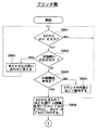
バスリセットの後、各ノードは新しいネットワーク構成を構築するために、各ノードにIDを与える動作に入る。このときの、バスリセットからノードID決定までの一般的なシーケンスを図23、図24、図25・図26のフローチャートを用いて説明する。図23のフローチャートはバスリセットの発生からノードIDが決定し、データ転送が行えるようになるまでの一連のバスの作業を示してある。
【0044】
先ず、ステップS2301として、ネットワーク内にバスリセットが発生することを常時監視していて、ここでノードの電源ON/OFFなどでバスリセットが発生するとステップS2302に移る。ステップS2302では、ネットワークがリセットされた状態から新たなネットワークの接続状況を知るために、直接接続されている各ノード間において親子関係の宣言がなされる。ステップS2303として全てのノード間で親子関係が決定すると、ステップS2304として一つのルートが決定する。全てのノード間で親子関係が決定するまで、ステップS2302の親子関係の宣言を行い、またルートも決定されない。
【0045】
ステップS2304でルートが決定されると、次はステップS2305として、各ノードにIDを与えるノードIDの設定作業が行われる。所定のノード順序でノードIDの設定が行われ、全てのノードにIDが与えられるまで繰り返し設定作業が行われ、最終的にステップS2306として、全てのノードにIDを登録し終えたら、新しいネットワーク構成が全てのノードにおいて認識されたので、ステップS2307としてノード間のデータ転送が行える状態となり、データ転送が開始される。このステップS2307の状態になると、再びバスリセットが発生するのを監視するモードに入り、バスリセットが発生したらステップS2301からステップS2306までの設定作業が繰り返し行われる。
【0046】
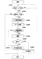
以上が図23のフローチャートの説明であるが、図23のフローチャートのバスリセットからルート決定までの部分と、ルート決定後からID設定終了までの手順をより詳しくフローチャートに表したものをそれぞれ図24、図25・図26に示す。先ず、図24のフローチャートの説明を行う。
【0047】
ステップS2401としてバスリセットが発生すると、ネットワーク構成は一旦リセットされる。尚、ステップS2401としてバスリセットが発生するのを常に監視している。次に、ステップS2402として、リセットされたネットワークの接続状況を再認識する作業の第一歩として各機器にリーフ(ノード)であることを示すフラグを立てておく。更に、ステップS2403として、各機器が自分の持つポートがいくつ他ノードと接続されているのかを調べる。ステップS2404のポート数の結果に応じて、これから親子関係の宣言を始めていくために、未定義(親子関係が決定されていない)ポートの数を調べる。バスリセットの直後はポート数=未定義ポート数であるが、親子関係が決定されていくに従って、ステップS2404で検知する未定義ポートの数は変化していくものである。
【0048】
先ず、バスリセットの直後、始めに親子関係の宣言を行えるのはリーフに限られている。リーフであるというのはステップS2403のポート数の確認で知ることができる。リーフは、ステップS2405として、自分に接続されているノードに対して、「自分は子、相手は親」と宣言し動作を終了する。ステップS2403でポート数が複数ありブランチと認識したノードは、バスリセットの直後はステップS2404で未定義ポート数>1ということなので、ステップS2406へと移り、先ずブランチというフラグが立てられ、ステップS2407でリーフからの親子関係宣言で「親」の受付をするために待つ。
【0049】
リーフが親子関係の宣言を行い、ステップS2407でそれを受けたブランチは適宜ステップS2404の未定義ポート数の確認を行い、未定義ポート数が1になっていれば残っているポートに接続されているノードに対して、ステップS2405の「自分が子」の宣言をすることが可能になる。2度目以降、ステップS2404で未定義ポート数を確認しても2以上あるブランチに対しては、再度ステップS2407でリーフまたは他のブランチからの「親」の受付をするために待つ。
【0050】
最終的に、いずれか1つのブランチ、または例外的にリーフ(子宣言を行えるのに素早く動作しなかったため)がステップS204の未定義ポート数の結果としてゼロになったら、これにてネットワーク全体の親子関係の宣言が終了したものであり、未定義ポート数がゼロ(全てのポートとして決定)になった唯一のノードはステップS2408としてルートのフラグが立てられ、ステップS2409としてルートとしての認識がなされる。このようにして、図24に示したバスリセットから、ネットワーク内全てのノード間における親子関係の宣言までが終了する。
【0051】
次に、図25・図26のフローチャートについて説明する。先ず、図24までのシーケンスでリーフ、ブランチ、ルートという各ノードのフラグの情報が設定されているので、これを元にして、ステップS2501でそれぞれ分類する。各ノードにIDを与える作業として、最初にIDの設定を行うことができるのはリーフからである。リーフ→ブランチ→ルートの順で若い番号(ノード番号=0〜)からIDの設定がなされていく。ステップS2502として、ネットワーク内に存在するリーフの数N(Nは自然数)を設定する。この後、ステップS2503として各自リーフがルートに対して、IDを与えるように要求する。この要求が複数ある場合には、ルートはステップS2504としてアービトレーション(1つに調停する作業)を行い、ステップS2505として勝ったノード1つにID番号を与え、負けたノードには失敗の結果通知を行う。
【0052】
ステップS2506として、ID取得が失敗に終わったリーフは再度ID要求を出し、同様の作業を繰り返す。IDを取得できたリーフからステップS2507として、そのノードのID情報をブロードキャスト(1つのノードからネットワーク上の不特定多数に向けた通信)で全ノードに転送する。1ノードID情報のブロードキャストが終わると、ステップS2508として残りのリーフの数が1つ減らされる。ここで、ステップS2509として、この残りのリーフの数が1以上ある時はステップS2503のID要求の作業からを繰り返し行い、最終的に全てのリーフがID情報をブロードキャストすると、ステップS2509がN=0となり、次はブランチのID設定に移る。
【0053】
ブランチのID設定もリーフの時と同様に行われる。先ず、ステップS2510として、ネットワーク内に存在するブランチの数M(Mは自然数)を設定する。この後、ステップS2511として各自ブランチがルートに対して、IDを与えるように要求する。これに対してルートは、ステップS2512としてアービトレーションを行い、勝ったブランチから順にリーフに与え終わった次の若い番号から与えていく。ステップS2513として、ルートは要求を出したブランチにID情報または失敗結果を通知し、ステップS2514として、ID取得が失敗に終わったブランチは再度ID要求を出し、同様の作業を繰り返す。
【0054】
IDを取得できたブランチからステップS2515として、そのノードのID情報をブロードキャストで全ノードに転送する。1ノードID情報のブロードキャストが終わると、ステップS2516として残りのブランチの数が1つ減らされる。ここで、ステップS2517として、この残りのブランチの数が1以上ある時はステップS2511のID要求の作業からを繰り返し、最終的に全てのブランチがID情報をブロードキャストするまで行われる。全てのブランチがノードIDを取得すると、ステップS2517はM=0となり、ブランチのID取得モードも終了する。
【0055】
ここまで終了すると、最終的にID情報を取得していないノードはルートのみなので、ステップS2518として、与えていない番号で若い番号を自分のID番号と設定し、ステップS2519として、ルートのID情報をブロードキャストする。以上で、図25・図26に示したように、親子関係が決定した後から全てのノードのIDが設定されるまでの手順が終了する。
【0056】
次に、一例として図27に示す実際のネットワークにおける動作を同図を参照しながら説明する。図27の説明として、(ルート)ノードBの下位にはノードAとノードCが直接接続されており、更にノードCの下位にはノードDが直接接続されており、更にノードDの下位にはノードEとノードFが直接接続された階層構造になっている。この、階層構造やルートノード、ノードIDを決定する手順を以下で説明する。
【0057】
バスリセットがされた後、先ず各ノードの接続状況を認識するために、各ノードの直接接続されているポート間において親子関係の宣言がなされる。この親子とは、親側が階層構造で上位となり、子側が下位となると言うことができる。図27では、バスリセットの後、最初に親子関係の宣言を行ったのはノードAである。基本的にノードの1つのポートにのみ接続があるノード(リーフと呼ぶ)から親子関係の宣言を行うことができる。これは自分には1ポートの接続のみということを先ず知ることができるので、これによってネットワークの端であることを認識し、その中で早く動作を行ったノードから親子関係が決定されていく。こうして親子関係の宣言を行った側(A−B間ではノードA)のポートが子と設定され、相手側(ノードB)のポートが親と設定される。こうして、ノードA−B間では子−親、ノードE−D間で子−親、ノードF−D間で子−親と決定される。
【0058】
更に1階層あがって、今度は複数個接続ポートを持つノード(ブランチと呼ぶ)のうち、他ノードからの親子関係の宣言を受けたものから順次、更に上位に親子関係の宣言を行っていく。図27では先ずノードDがD−E間、D−F間と親子関係が決定した後、ノードCに対する親子関係の宣言を行っており、その結果ノードD−C間で子−親と決定している。ノードDからの親子関係の宣言を受けたノードCは、もう一つのポートに接続されているノードBに対して親子関係の宣言を行っている。これによってノードC−B間で子−親と決定している。このようにして、図27のような階層構造が構成され、最終的に接続されている全てのポートにおいて親となったノードBが、ルートノードと決定された。ルートは1つのネットワーク構成中に一つしか存在しないものである。
【0059】
尚、この図27においてノードBがルートノードと決定されたが、これはノードAから親子関係宣言を受けたノードBが、他のノードに対して親子関係宣言を早いタイミングで行っていれば、ルートノードは他ノードに移っていたこともあり得る。即ち、伝達されるタイミングによってはどのノードもルートノードとなる可能性があり、同じネットワーク構成でもルートノードは一定とは限らない。ルートノードが決定すると、次は各ノードIDを決定するモードに入る。ここでは全てのノードが、決定した自分のノードIDを他の全てのノードに通知する(ブロードキャスト機能)。自己ID情報は、自分のノード番号、接続されている位置の情報、持っているポートの数、接続のあるポートの数、各ポートの親子関係の情報等を含んでいる。ノードID番号の割り振りの手順としては、先ず1つのポートにのみ接続があるノード(リーフ)から起動することができ、この中から順にノード番号=0、1、2、…と割り当てられる。ノードIDを手にしたノードは、ノード番号を含む情報をブロードキャストで各ノードに送信する。これによって、そのID番号は「割り当て済み」であることが認識される。
【0060】
全てのリーフが自己ノードIDを取得し終わると、次はブランチへ移りリーフに引き続いたノードID番号が各ノードに割り当てられる。リーフと同様に、ノードID番号が割り当てられたブランチから順次ノードID情報をブロードキャストし、最後にルートノードが自己ID情報をブロードキャストする。即ち、常にルートは最大のノードID番号を所有するものである。以上のようにして、階層構造全体のノードIDの割り当てが終わり、ネットワーク構成が再構築され、バスの初期化作業が完了する。
【0061】
《アービトレーション》
1394シリアルバスでは、データ転送に先立って必ずバス使用権のアービトレーション(調停)を行う。1394シリアルバスは個別に接続された各機器が、転送された信号をそれぞれ中継することによって、ネットワーク内全ての機器に同信号を伝えるように論理的なバスネットワークであるので、パケットの衝突を防ぐ意味でアービトレーションは必要である。これによって、ある時間には、たった一つのノードのみ転送を行うことができる。アービトレーションを説明するための図として図28(a)にバス使用要求の図、図28(b)にバス使用許可の図を示し、以下これを用いて説明する。
【0062】
アービトレーションが始まると、1つもしくは複数のノードが親ノードに向かって、それぞれバス使用権の要求を発する。図28(a)のノードCとノードFがバス使用権の要求を発しているノードである。これを受けた親ノード(図28ではノードA)は更に親ノードに向かって、バス使用権の要求を発する(中継する)。この要求は最終的に調停を行うルートに届けられる。
【0063】
バス使用要求を受けたルートノードは、どのノードにバスを使用させるかを決める。この調停作業はルートノードのみが行えるものであり、調停によって勝ったノードにはバスの使用許可を与える。図28(b)はノードCに使用許可が与えられ、ノードFの使用は拒否された図である。アービトレーションに負けたノードに対してはDP(Data Prefix)パケットを送り、拒否されたことを知らせる。拒否されたノードのバス使用要求は次回のアービトレーションまで待たされる。
【0064】
以上のようにして、アービトレーションに勝ってバスの使用許可を得たノードは、以降データの転送を開始できる。ここで、アービトレーションの一連の流れを図29のフローチャートに示して説明する。ノードがデータ転送を開始できるためには、バスがアイドル状態であることが必要である。先に行われていたデータ転送が終了して、現在バスが空き状態であることを認識するためには、各転送モードで個別に設定されている所定のアイドル時間ギャップ長(例、サブアクション・ギャップ)を経過することによって、各ノードは自分の転送が開始できると判断する。
【0065】
ステップS2901として、Asyncデータ、Isoデータ等それぞれ転送するデータに応じた所定のギャップ長が得られたか判断する。所定のギャップ長が得られない限り、転送を開始するために必要なバス使用権の要求はできないので、所定のギャップ長が得られるまで待つ。ステップS2901で所定のギャップ長が得られたら、ステップS2902として転送すべきデータがあるか判断し、転送するデータがある場合は、ステップS2903として、転送するためにバスを確保するようバス使用権の要求をルートに対して発する。このときのバス使用権の要求を表す信号の伝達は、図28に示したように、ネットワーク内各機器を中継しながら最終的にルートに届けられる。ステップS2902で転送するデータがない場合は、そのまま待機する。
【0066】
次に、ステップS2904として、ステップS2903のバス使用要求を1つ以上ルートが受信したら、ルートはステップS2905として、使用要求を出したノードの数を調べる。ステップS2905での選択値がノード数=1(使用権要求を出したノードは1つ)だったら、そのノードに直後のバス使用許可が与えられることとなる。ステップS2905での選択値がノード数>1(使用要求を出したノードは複数)だったら、ルートはステップS2906として、使用許可を与えるノードを1つに決定する調停作業を行う。この調停作業は公平なものであり、毎回同じノードばかりが許可を得るようなことはなく、平等に権利を与えていくような構成となっている。
【0067】
ステップS2907として、ステップS2906で使用要求を出した複数ノードの中からルートが調停して使用許可を得た1つのノードと、敗れたその他のノードに分ける選択を行う。ここで、調停されて使用許可を得た1つのノード、またはステップS2905の選択値から使用要求ノード数=1で調停無しに使用許可を得たノードには、ステップS2908として、ルートはそのノードに対して許可信号を送る。許可信号を得たノードは、受け取った直後に転送すべきデータ(パケット)を転送開始する。また、ステップS2906の調停で敗れてバス使用が許可されなかったノードには、ステップS2906として、ルートからアービトレーション失敗を示す上記のDPパケットを送られ、これを受け取ったノードは再度転送を行うためのバス使用要求を出すため、ステップS2901まで戻り、所定ギャップ長が得られるまで待機する。以上がアービトレーションの流れを説明した図29のフローチャートの説明である。
【0068】
《Asynchronous(非同期)転送》
アシンクロナス転送は非同期転送である。図30にアシンクロナス転送における時間的な遷移状態を示す。図30のサブアクション・ギャップは、バスのアイドル状態を示すものである。このアイドル時間が一定値になった時点で、転送を希望するノードはバスが使用できると判断して、バス獲得のためのアービトレーションを実行する。アービトレーションでバスの使用許可を得ると、次にデータの転送がパケット形式で実行される。データ転送後、受信したノードは転送されたデータに対しての受信結果のack(受信確認用返送コード)をack gapという短いギャップの後、返送して応答するか、応答パケットを送ることによって転送が完了する。ackは4ビットの情報と4ビットのチェックサムからなり、成功か、ビジー状態か、ペンディング状態であるかといった情報を含み、すぐに送信元ノードに返送される。
【0069】
次に、図31にアシンクロナス転送のパケットフォーマットの例を示す。パケットには、データ部及び誤り訂正用のデータCRC(Cyclic Redundancy Check)の他にはヘッダ部があり、そのヘッダ部には図31に示すような、目的ノードID、ソースノードID、転送データ長さや各種コードなどが書き込まれ、転送が行われる。また、アシンクロナス転送は自己ノードから相手ノードへの1対1の通信である。転送元ノードから転送されたパケットは、ネットワーク中の各ノードに行き渡るが、自分宛てのアドレス以外のものは無視されるので、宛先の1つのノードのみが読み込むことになる。以上がアシンクロナス転送の説明である。
【0070】
《Isochronous(同期)転送》
アイソクロナス転送は同期転送である。1394シリアルバスの最大の特徴であるともいえるこのアイソクロナス転送は、特にVIDEO映像データや音声データといったマルチメディアデータなど、リアルタイムな転送を必要とするデータの転送に適した転送モードである。また、アシンクロナス転送(非同期)が1対1の転送であったのに対し、このアイソクロナス転送はブロードキャスト機能によって、転送元の1つのノードから他の全てのノードへ一様に転送される。
【0071】
図32はアイソクロナス転送における時間的な遷移状態を示す図である。アイソクロナス転送は、バス上一定時間毎に実行される。この時間間隔をアイソクロナスサイクルと呼ぶ。アイソクロナスサイクル時間は125μsである。この各サイクルの開始時間を示し、各ノードの時間調整を行う役割を担っているのがサイクル・スタート・パケットである。サイクル・スタート・パケットを送信するのは、サイクル・マスタと呼ばれるノードであり、1つ前のサイクル内の転送終了後、所定のアイドル期間(サブアクション・ギャップ)を経た後、本サイクルの開始を告げるサイクル・スタート・パケットを送信する。このサイクル・スタート・パケットの送信される時間間隔が125μsとなる。
【0072】
また、図32にチャネルA、チャネルB、チャネルCと示したように、1サイクル内において複数種のパケットがチャネルIDをそれぞれ与えられることによって、区別して転送できる。これによって同時に複数ノード間でのリアルタイムな転送が可能であり、また受信するノードでは自分が欲しいチャネルIDのデータのみを取り込む。このチャネルIDは送信元のアドレスを表すものではなく、データに対する論理的な番号を与えているに過ぎない。よって、あるパケットの送信は1つの送信元ノードから他の全てのノードに行き渡るブロードキャストで転送されることになる。
【0073】
アイソクロナス転送のパケット送信に先立って、アシンクロナス転送同様アービトレーションが行われる。しかし、アシンクロナス転送のように1対1の通信ではないので、アイソクロナス転送にはack(受信確認用返信コード)は存在しない。また、図32に示したiso gap(アイソクロナスギャップ)とは、アイソクロナス転送を行う前にバスが空き状態であると認識するために必要なアイドル期間を表している。この所定のアイドル期間を経過すると、アイソクロナス転送を行いたいノードはバスが空いていると判断し、転送前のアービトレーションを行うことができる。
【0074】
次に、図33にアイソクロナス転送のパケットフォーマットの例を示し、説明する。各チャネルに分かれた各種のパケットには、それぞれデータ部及び誤り訂正用のデータCRCの他にヘッダ部があり、そのヘッダ部には図33に示したような転送データ長やチャネルNO、その他各種コード及び誤り訂正用のヘッダCRCなどが書き込まれ、転送が行われる。以上がアイソクロナス転送の説明である。
【0075】
《バス・サイクル》
実際の1394シリアルバス上の転送では、アイソクロナス転送とアシンクロナス転送は混在できる。その時のアイソクロナス転送とアシンクロナス転送が混在したバス上の転送状態の時間的な遷移の様子を表した図を図34に示す。アイソクロナス転送はアシンクロナス転送より優先して実行される。その理由は、サイクル・スタート・パケットの後、アシンクロナス転送を起動するために必要なアイドル期間のギャップ長(サブアクション・ギャップ)よりも短いギャップ長(アイソクロナス・ギャップ)で、アイソクロナス転送を起動できるからである。従って、アシンクロナス転送よりアイソクロナス転送は優先して実行されることになる。
【0076】
図34に示した一般的なバスサイクルにおいて、サイクル#mのスタート時にサイクル・スタート・パケットがサイクル・マスタから各ノードに転送される。これによって、各ノードで時刻調整を行い、所定のアイドル期間(アイソクロナス・ギャップ)を待ってからアイソクロナス転送を行うべきノードはアービトレーションを行い、パケット転送に入る。図34ではチャネルeとチャネルsとチャネルkが順にアイソクロナス転送されている。
【0077】
このアービトレーションからパケット転送までの動作を、与えられているチャネル分繰り返し行った後、サイクル#mにおけるアイソクロナス転送が全て終了したら、アシンクロナス転送を行うことができるようになる。アイドル時間がアシンクロナス転送が可能なサブアクション・ギャップに達することによって、アシンクロナス転送を行いたいノードはアービトレーションの実行に移れると判断する。但し、アシンクロナス転送が行える期間は、アイソクロナス転送終了後から、次のサイクル・スタート・パケットを転送すべき時間(cycle synch)までの間にアシンクロナス転送を起動するためのサブアクション・ギャップが得られた場合に限っている。
【0078】
図34のサイクル#mでは3つのチャネル分のアイソクロナス転送と、その後アシンクロナス転送(含むack)が2パケット(パケット1、パケット2)転送されている。このアシンクロナスパケット2の後は、サイクル#m+1をスタートすべき時間(cycle synch)に至るので、サイクル#mでの転送はここまでで終わる。但し、非同期または同期転送動作中に次のサイクル・スタート・パケットを送信すべき時間(cycle synch)に至ったとしたら、無理に中断せずに、その転送が終了した後のアイドル期間を待ってから次サイクルのサイクル・スタート・パケットを送信する。即ち、1つのサイクルが125μs以上続いたときは、その分、次サイクルは基準の125μsより短縮されたとする。
【0079】
このようにアイソクロナス・サイクルは125μsを基準に超過、短縮し得るものである。しかし、アイソクロナス転送はリアルタイム転送を維持するために毎サイクル必要であれば必ず実行され、アシンクロナス転送はサイクル時間が短縮されたことによって次以降のサイクルにまわされることもある。こういった遅延情報も含めて、サイクル・マスタによって管理される。以上がIEEE1394シリアルバスの説明である。
【0080】
次に、上記図3に示した本発明の実施の形態に係る印刷システムを構成するプリンタ103、パーソナルコンピュータ(PC)101の詳細構成を図1及び図2に基づき説明する。
【0081】
図1は上記図3に示した本発明の実施の形態に係る印刷システムのプリンタ103の詳細構成を示すブロック図である。本発明の実施の形態に係る印刷システムのプリンタ103は、IEEE1394I/F部201と、コードメモリ領域202a・ビットイメージデータメモリ領域202b・文章情報メモリ領域202cを有するRAM202と、操作/表示部203と、CPU204と、ROM205と、印刷部I/F部207と、印刷部208と、システムバス209とを備える構成となっている。
【0082】
上記各部の構成を詳述すると、IEEE1394I/F部201は、プリンタ103へのパーソナルコンピュータ(PC)101からの印刷可能状態か否かの問い合わせに対する応答、印刷開始命令の受信、コマンドブロックの受信等に用いられる。RAM202のコードメモリ領域202aは、PC101からIEEE1394I/Fシリアルバス106を通じて読み出した文章データをストアする領域である。RAM202のビットイメージデータメモリ領域202bは、文章データをビットイメージに変換したデータをストアする領域である。RAM202の文章情報メモリ領域202cは、その他の用途に用いられる領域である。操作/表示部203は、プリンタ103の状態を表示したり、オペレータのコマンドの入力に用いられる。
【0083】
CPU204は、プリンタ各部を制御するものであり、後述の図8乃至図15のフローチャートに示す処理を実行する。ROM205は、CPU204の動作プログラム等をストアする。印刷部I/F部207は、RAM202内に展開されたビットイメージデータを印刷部208から送られてくる水平及び垂直同期信号に同期して読み出し、印刷部208へ送る。印刷部208は、印刷部I/F部207を通じて送られてくるVIDEOデータを入力し、用紙等の記録媒体上に印刷する。システムバス209は、上記各部間における信号が伝送される共通信号路である。
【0084】
尚、本発明の実施の形態では、上記図1及び図3に示すプリンタとして例えばレーザビームプリンタを例に挙げているが、本発明は、レーザビームプリンタに限定されるものではなく、インクジェット式プリンタ、熱転写式プリンタ、感熱式プリンタ、静電式プリンタ、放電破壊式プリンタなど各種プリンタに適用することが可能である。
【0085】
図2は上記図3に示した本発明の実施の形態に係る印刷システムのPC101の詳細構成を示すブロック図である。本発明の実施の形態に係る印刷システムのPC101は、表示部301と、操作部302と、ハードディスク303と、コマンドブロック部304a・データブロック部304b・その他の領域304cを有するメモリ304と、CPU305と、IEEE1394I/F部306と、FIFO(First In First Outメモリ)307と、システムバス308とを備える構成となっている。
【0086】
上記各部の構成を詳述すると、表示部301は、文字や画像等を表示する例えばCRT等のディスプレイである。尚、表示方式はCRTに限定されず液晶等でもよい。操作部302は、キーボードやマウス等として構成される。ハードディスク303は、各種データを格納する。メモリ304のコマンドブロック部304aには、後述のコマンドブロックが作成される。メモリ304のデータブロック部304bには、後述のデータブロックが作成される。メモリ304のその他の領域304cは、その他のデータの格納に用いられる。
【0087】
CPU305は、PC各部を制御するものであり、後述の図16及び図17のフローチャートに示す処理を実行する。IEEE1394I/F部306は、PC101からプリンタ103に対する印刷可能状態か否かの問い合わせ、印刷開始命令の送信、コマンドブロックの送信等に用いられる。FIFO307は、先入れ先出しメモリであり、ステータスの入力に用いられる。システムバス308は、上記各部間における信号が伝送される共通信号路である。
【0089】
図4及び図5は本発明の実施の形態に係る印刷システムのPCのメモリ304に作成されるコマンドブロック及びデータブロックの構成(メモリ304内に作成される文章データの構成)を示す説明図である。本実施形態においては、例えば4ページの構成の文章データをプリンタ103に送って印刷する場合について説明する。
【0090】
図4において401〜405は、PCのメモリ304のコマンドブロック部304aに作成されるコマンドブロックであり、406〜409は、PCのメモリ304のデータブロック部304bに作成されるデータブロックである。本実施形態においては、各データブロックは各ページの1ページ分の文章データを含む。また、各ページの文章データの最後には終了を示すコードが付く。
【0091】
コマンドブロックのうち405は、コマンドブロックの終了をプリンタに知らせる終了コードを含む終了コマンドブロックである。401〜404の各コマンドブロックは、第一段目にプリンタに指示するコマンドの内容を示す領域(本実施形態の場合はWriteコマンド)、第二段目に対応するデータブロックの先頭アドレス情報、第三段目に次のコマンドブロックの先頭アドレス情報から構成される。例えばコマンドブロック401は、第一段目がWriteコマンド、第二段目がデータブロック406の先頭アドレス、第三段目がコマンドブロック402の先頭アドレスである。
【0092】
図6は本発明の実施の形態に係る印刷システムのプリンタの印刷部の概略構造を示す構成図である。本発明の実施の形態に係る印刷システムのプリンタの印刷部は、半導体レーザ501、回転ミラー502、モータ503、感光ドラム504、転写器505、用紙収納部506、ピックアップローラ507、現像器508、定着器509、排紙ローラ511、排紙部512、給紙センサ515、排紙センサ516を備えている。
【0093】
上記各部の構成を詳述すると、半導体レーザ501は、ビットイメージに応じてON・OFF駆動され、レーザ光を発射する。回転ミラー502は、モータ503によって駆動され、ビットイメージデータでON、OFF変調された半導体レーザ501の出力を感光ドラム504に照射する。モータ503は、回転ミラー502を駆動する。感光ドラム504は、レーザ光に基づきドラム表面に潜像が形成される。転写器505は、感光ドラム504上に形成された潜像を印刷用紙に転写する。用紙収納部506は、用紙を収納する。ピックアップローラ507は、用紙収納部506内の用紙を適当なタイミングでピックアップするものであり、用紙は順次ローラによって感光ドラム504まで送り込まれる。
【0094】
現像器508は、用紙の現像を行う。定着器509は、トナーを用紙に定着させる。排紙ローラ511は、定着された用紙を排紙部512に送り出す。排紙部512は、用紙の排紙を行う。給紙センサ515は、当該給紙センサ515の前を用紙が通過したことを検知すると検知信号をCPU204に出力する。この場合、CPU204は検知信号に基づき用紙の進行方向の同期をとり、用紙の所望の位置に印字ができるようにタイミングを合わせるわけである。排紙センサ516は、当該排紙センサ516の前を用紙が通過したことを検知すると検知信号をCPU204に出力する。
【0095】
図7は本発明の実施の形態に係る印刷システムにおける印刷開始コマンド及び印刷終了ステータスを示す図であり、(a)はPC101からプリンタ103に対する印刷開始コマンドを示す説明図、(b)はプリンタ103からPC101に対する印刷終了ステータスを示す説明図である。図7(a)において701はプリント開始コマンド、702はコマンドブロック先頭アドレス、703は終了コードを示す。また、図7(b)において704は印刷終了ステータス、705はページ番号、706は終了コードを示す。
【0096】
次に、上記の如く構成された本発明の実施の形態に係る印刷システムを構成するPC101及びプリンタ103の動作を図1乃至図17、並びに図35を参照しながら説明する。図8乃至図15は本発明の実施の形態に係る印刷システムのプリンタ103の動作の流れを示すフローチャート、図16及び図17は本発明の実施の形態に係る印刷システムのPC101の動作の流れを示すフローチャートである。
【0097】
先ず、図16及び図17において、印刷システムのPC101側の動作を説明する。PC101のCPU305は、アプリケーションプログラムを用いて文章を作成する(ステップS1601)。操作部(キーボード)302からの印刷指示により(ステップS1602)、上記文章を印刷用の文章データとして作成し、メモリ304上にストアする(ステップS1603)。文章データがメモリ304にストアされ準備ができると、PC101のCPU305はプリンタ103に対し、IEEE1394シリアルバスを介して印刷可能状態(レディ状態)か否かを問い合わせる(ステップS1604)。印刷可能状態で無い場合、表示部301に印刷可能状態で無い旨を表示する(ステップS1606)。印刷可能状態の場合、PC101からプリンタ103に対し、印刷開始命令を送出すると共に、先頭のコマンドブロック401の先頭アドレスを送出する(ステップS1607)。
【0098】
その後、プリンタ103における印刷終了に伴い、PC101はプリンタ103から当該ページの印刷終了ステータスを入力すると(ステップS1608)、次の印刷対象ページが有る場合(ステップS1609)、次の印刷対象ページのコマンドブロックとデータブロックを作成しつなげる処理を行う。最終ページの場合はコマンドブロックの前後に終了コードを付加する処理を行う(ステップS1608)。この後、PC101はプリンタ103から全ページの印刷終了ステータスを入力すると(ステップS1611)、本処理を終了する。
【0099】
続いて、図8乃至図15において、印刷システムのプリンタ103側の動作を説明する。プリンタ103のCPU204はPC101からコマンドを入力すると(ステップS801)、入力コマンドがプリンタ103の状態を問い合わせるコマンドか否かを判定する(ステップS802)。状態問い合わせコマンドの場合、PC101からの問い合わせに応答する(ステップS803)。状態問い合わせコマンドでない場合、PC101からの印刷開始命令か否かを判定する(ステップS804)。PC101からの印刷開始命令でない場合、プリンタ103はコマンドの内容に応じて動作を行い(ステップS805)、ステップS801へ戻る。
【0100】
プリンタ103のCPU204はPC101から印刷開始命令を受けた場合、コマンドに付随して送られてくるコマンドブロックの先頭アドレス情報を元に、IEEE1394シリアルバスを通じてPC101のメモリ304内のコマンドブロック401にアクセスする。コマンドブロック401にはWriteコマンドが書かれているので、プリンタ103は印刷要求を認識し、次にコマンドブロック401内のデータブロックの先頭アドレス情報からデータブロック406にアクセスする(ステップS806)。そして、データブロック406の1ページ目の文章データを読み出し、IEEE1394シリアルバスを通じてプリンタ103のRAM202内のコードメモリ領域202aにロードする(ステップS807)。
【0101】
データブロック406から1ページ分の文章データを読み出し終わると、次にプリンタ103のCPU204は上記コードメモリ領域202aにストアした文章データ(PDL(Page Description Language)データ)を読み出し、内容を解析してビットイメージに変換し、RAM202内のビットイメージデータメモリ領域202bにストアする(ステップS808)。上記ビットイメージへの変換が終了すると(ステップS809)、CPU204は印刷部208に印刷開始コマンドを出す(ステップS810)。印刷開始コマンドを受けた印刷部208は、回転ミラー502と感光ドラム504の回転を開始し、またピックアップローラ507を起動して印刷用紙を上述した感光ドラム504、転写器505、現像器508、定着器509等からなる印刷部208へ送り込む。
【0102】
一方、CPU204はコマンドブロック401の三段目の次コマンドブロックの先頭アドレス情報からコマンドブロック402にアクセスし、同様の手順でデータブロック407から2ページ目の文章データを読み出し、RAM202のコードメモリ領域202aにロードし始める(ステップS812)。
【0103】
さて、印刷用紙が給紙センサ515の位置に達すると(図35(a))、給紙センサ515からセンス信号がCPU204に送られてくる(ステップS813)。この給紙センサ515からのセンス信号をタイミング信号として、CPU204は、用紙収納部506から繰り出され定速で搬送される用紙の先端と、半導体レーザ501により感光ドラム504に書き込まれた潜像の先端が一致するタイミングで、RAM202からビットイメージデータを読み出し、印刷部208へ送り出す(ステップS815)。
【0104】
一方で、CPU204は上記給紙センサ515からのセンス信号がONになってからOFFになるまでの時間を計測する(ステップS816)。正常に用紙が搬送されていれば用紙は定速で搬送されるので、給紙センサ515の前を用紙が通過する時間は一定となり、従って上記給紙センサ515からのセンス信号がONになってからOFFになるまでの時間も一定である。しかしながら上記給紙センサ515の信号が一定時間を過ぎてもOFFにならなかったり(ステップS817)、上記一定時間以上経過してからOFFした場合は(ステップS819)、用紙搬送に異常が発生したことが考えられ、従って用紙上に転写されるはずの画像も異常であることが考えられる。この異常が発生した場合の処置については後述することとして、先ずは給紙センサ515を用紙が正常に通過した場合について述べる。
【0105】
RAM202からのビットイメージデータの読み出しを終了すると(ステップS819)、CPU204は、次のページのデータをPC101のデータブロックからロードし終えていない場合は、データのロードを継続し、データのロードを終了した場合は、RAM202のコマンドデータを読み出しビットイメージへの変換を行うと共に、次のページの印刷用紙の給紙を行う(ステップS827、図35(d))。
【0106】
一方、転写器505で画像が転写された用紙は、定着器509で定着されて、排紙センサ516の前を通過する(図35(d))。上述のように用紙の搬送速度は一定であるので、用紙が給紙センサ515の前を通過してから排紙センサ516の前に達する時間は一定である。従って、上記一定時間を過ぎても排紙センサ516の前に用紙が達し、排紙センサ516の信号がONにならない場合(ステップS829)や、排紙センサ516の信号がONした後、一定時間以内にOFFにならない場合(ステップS831)は、用紙搬送に異常が発生したと考えられるので、用紙異常処理ルーチンに飛ぶが、このルーチンでの処理は後述することにして、ここでは排紙センサ516の前を用紙が正常に通過した場合(ステップS830)について述べる。
【0107】
この場合は、用紙上のページが正常に印刷され排紙されたと判断できるので、プリンタ103のCPU204はPC101に対してこのページの印刷が正常に終了したことを示すステータスをPC101のFIFO307に書き込み(ステップS832)、上記ステップS809へ戻り次のページの処理を継続する。
【0108】
一方、PC101は上記終了ステータスを入力すると(上記ステップS1608)、次のページの文章データが有る場合は、上記図5に示す如く先ずコマンドブロック401のデータブロック(この場合は406)の先頭アドレスデータを情報が無いことを示す“FFFFFFFF"に書き換え、コマンドブロック404の次に次のページのコマンドブロック410をつなげ、文章データ自体は終了ステータスを受けたページの文章データが有った位置(この場合は406)にロードする。このようにしてPC101はプリンタ103から終了ステータスを受けると、そのページのコマンドブロックのデータブロックアドレス情報を“FFFFFFFF"に書き換え、次のページのコマンドブロックを終了コードの直前につなげ、その文章データは終了ステータスを受けた空いたデータブロックに書き込むという作業を最終ページまで行う。
【0109】
一方、プリンタ103はコマンドブロックの中の次のコマンドブロックのアドレスが示すデータが終了コードを示すまで(即ちそのページは最終ページであることを示す)上記作業を繰り返し、最終ページの排紙が終了したところで作業を終了する。
【0110】
次に、プリンタ103において用紙搬送異常を検知した際の動作を説明する。CPU204は排紙センサ516の信号に基づき用紙の搬送異常を検知すると、印刷部208の印刷作業を中断させ、操作/表示部203に「ヨウシ イジョウ」を表示すると共に、PC101に対して用紙搬送異常が生じたことを通知する(ステップS822)。PC101は上記ステータスを受けて、表示部301に「プリンタに用紙搬送異常が発生しました」というメッセージを表示する。この時、プリンタ103は当然ノンレディ状態になる。この場合、プリンタ103の中で用紙ジャムが発生した可能性が高いので、オペレータはプリンタ103のジャムを発生した用紙を取り除く等の復旧作業を行う。
【0111】
一方、プリンタ103のCPU204はPC101にアクセスして、用紙異常を発生したページの文章データ(印刷終了ステータスを返していないのでPC101のメモリに保存されている)をデータブロックから読み出し、RAM202のコードメモリ領域202aにロードし直す(ステップS823)。データの再ロードを完了すると(ステップS824)、RAM202のデータを再びビットイメージに変換し(ステップS825)、プリンタレディになるのを待って(ステップS826)、印刷し直す。
【0112】
尚、上述した本発明の実施の形態においては、プリンタ103で片面印刷を行う場合のみを説明したが、本発明は両面印刷を行う場合にも適用できることは言うまでもない。この場合は、例えば1ページ目(1枚目の表面)→3ページ目(2枚目の表面)→2ページ目(1枚目の裏面)→4ページ目(2枚目の裏面)といった順番で印刷が行われるのであるが、例えば1枚目がジャムになった場合は1ページ目と2ページ目の文章データをPC101から再ロードして印刷し直せばよいわけである。
【0113】
以上説明したように、本発明の実施の形態に係る印刷システムによれば、PC101は、プリンタ103と通信を行うIEEE1394I/F部306と、プリンタ103からアクセス可能で文章データを格納するメモリ304と、文章データのアドレス情報を含む情報ブロックをプリンタ103に通知し、印刷完了ステータスの受信に基づき印刷が完了したページの文章データをクリアして次の印刷対象ページの文章データを上記クリアした位置にロードするCPU305とを有し、プリンタ103は、PC101と通信を行うIEEE1394I/F部201と、用紙等の記録媒体に印刷を行う印刷部208と、PC101から通知された文章データのアドレス情報を含む情報ブロックのアドレスに基づきPC101のメモリ304に格納されている文章データを読み出し印刷部208で印刷を実行させ、文章データの印刷が完了した旨及び印刷が完了したページ情報をPC101へステータスとして返送するCPU204とを有するため、下記のような作用及び効果を奏する。
【0114】
上記構成において、文章データをPC101のメモリ304に格納しておき、プリンタ103で印刷を行う場合は文章データをPC101のメモリ304から読み出して印刷するため、プリンタ103側の受信バッファメモリの容量が非常に少なくて済む。また、ジャムが発生した場合は、ジャムリカバリのための文章データをプリンタ103がPC101の介在無しに直接PC101上のメモリ304から読み出すことができるため、PC101側の負担は非常に少ない。また、印刷が完了したページについてはプリンタ103からPC101に対して印刷完了を通知するため、PC101はいつまでも文章データを保持する必要が無く、印刷が完了したページについては次の文章データを書き込んでプリンタ103に印刷させてもよいし、他に文章データが無い場合は他の用途に用いることができる。
【0115】
即ち、本発明の実施の形態においては、プリンタ103側の受信バッファメモリの容量が非常に少なくて済み、且つPC101側の負担も非常に少ない高効率の印刷システムを実現できるという効果がある。
【0116】
上述した本発明の実施の形態に係る印刷システムにおいては、PC101にIEEE1394インタフェースシリアルバス106を介してスキャナ102、プリンタ103、デジタルカメラ104、HDD105等を接続する構成としたが、本発明は上記システム構成に限定されるものではなく、必要に応じて他の機器を接続する構成とすることも可能である。
【0117】
尚、本発明は、複数の機器から構成されるシステムに適用しても、1つの機器からなる装置に適用してもよい。前述した実施形態の機能を実現するソフトウエアのプログラムコードを記憶した記憶媒体を、システム或いは印刷システムに供給し、そのシステム或いは装置のコンピュータ(またはCPUやMPU)が記憶媒体に格納されたプログラムコードを読み出し実行することによっても、達成されることは言うまでもない。
【0118】
この場合、記憶媒体から読み出されたプログラムコード自体が前述した実施形態の機能を実現することになり、そのプログラムコードを記憶した記憶媒体は本発明を構成することになる。
【0119】
プログラムコードを供給するための記憶媒体としては、例えば、フロッピディスク、ハードディスク、光ディスク、光磁気ディスク、CD−ROM、CD−R、磁気テープ、不揮発性のメモリカード、ROMなどを用いることができる。
【0120】
また、コンピュータが読出したプログラムコードを実行することにより、前述した実施形態の機能が実現されるだけでなく、そのプログラムコードの指示に基づき、コンピュータ上で稼働しているOSなどが実際の処理の一部または全部を行い、その処理によって前述した実施形態の機能が実現される場合も含まれることは言うまでもない。
【0121】
更に、記憶媒体から読出されたプログラムコードが、コンピュータに挿入された機能拡張ボードやコンピュータに接続された機能拡張ユニットに備わるメモリに書込まれた後、そのプログラムコードの指示に基づき、その機能拡張ボードや機能拡張ユニットに備わるCPUなどが実際の処理の一部または全部を行い、その処理によって前述した実施形態の機能が実現される場合も含まれることは言うまでもない。
【0123】
【発明の効果】
以上説明したように、本発明によれば、上位装置はいつまでも印刷データを保持する必要が無く、印刷が完了したページについては次の印刷データを書き込んで印刷装置に印刷させてもよいし、他に文章データが無い場合は他の用途に用いることができるという効果に加えて、特に次の効果を奏する。
印刷装置において印刷が完了した場合には、その旨が上位装置に通知されるので、上位装置では印刷装置からの印刷完了通知によって、印刷データをメモリから消去してよいことを知ることができる。また、印刷装置において紙送りエラーが発生した場合には、上位装置に前記通知を行うことなく、印刷データを再ロードするので、印刷装置では上位装置に印刷データを消去させずに、エラーによって改めて必要になった印刷データを確実にロードし直すことができる。
【図面の簡単な説明】
【図1】本発明の実施の形態に係る印刷システムのプリンタの構成を示すブロック図である。
【図2】本発明の実施の形態に係る印刷システムのPC(パーソナルコンピュータ)の構成を示すブロック図である。
【図3】本発明の実施の形態に係る印刷システムの全体構成を示す構成図である。
【図4】本発明の実施の形態に係る印刷システムのPCのメモリに作成されるコマンドブロック及びデータブロックの構成を示す説明図である。
【図5】本発明の実施の形態に係る印刷システムのPCのメモリに作成されるコマンドブロック及びデータブロックの構成を示す説明図である。
【図6】本発明の実施の形態に係る印刷システムのプリンタの印刷部の概略構造を示す構成図である。
【図7】本発明の実施の形態に係る印刷システムにおける印刷開始コマンド及び印刷終了ステータスを示す説明図であり、(a)はPCからプリンタに対する印刷開始コマンドを示す説明図、(b)はプリンタからPCに対する印刷終了ステータスを示す説明図である。
【図8】本発明の実施の形態に係る印刷システムのプリンタの動作の流れを示すフローチャートである。
【図9】本発明の実施の形態に係る印刷システムのプリンタの動作の流れを示すフローチャートである。
【図10】本発明の実施の形態に係る印刷システムのプリンタの動作の流れを示すフローチャートである。
【図11】本発明の実施の形態に係る印刷システムのプリンタの動作の流れを示すフローチャートである。
【図12】本発明の実施の形態に係る印刷システムのプリンタの動作の流れを示すフローチャートである。
【図13】本発明の実施の形態に係る印刷システムのプリンタの動作の流れを示すフローチャートである。
【図14】本発明の実施の形態に係る印刷システムのプリンタの動作の流れを示すフローチャートである。
【図15】本発明の実施の形態に係る印刷システムのプリンタの動作の流れを示すフローチャートである。
【図16】本発明の実施の形態に係る印刷システムのPCの動作の流れを示すフローチャートである。
【図17】本発明の実施の形態に係る印刷システムのPCの動作の流れを示すフローチャートである。
【図18】1394シリアルバスを用いて構成されるネットワーク・システムの例を示すブロック図である。
【図19】1394シリアルバスの構成要素を示すを示すブロック図である。
【図20】1394シリアルバスにおけるアドレス空間を示す説明図である。
【図21】1394シリアルバス・ケーブルを示す断面図である。
【図22】1394シリアルバスで採用されているデータ転送フォーマットのDS−Link符号化方式を示す説明図である。
【図23】バスリセットの発生からノードIDが決定しデータ転送が行えるようになるまでの一連のバスの作業を示すフローチャートである。
【図24】バスリセットからルート決定までの部分とルート決定後からID設定終了までの手順をより詳細に示すフローチャートである。
【図25】バスリセットからルート決定までの部分とルート決定後からID設定終了までの手順をより詳細に示すフローチャートである。
【図26】バスリセットからルート決定までの部分とルート決定後からID設定終了までの手順をより詳細に示すフローチャートである。
【図27】実際のネットワークにおける動作を説明するためのブロック図である。
【図28】アービトレーションを説明するためのブロック図であり、(a)はバス使用要求を示すブロック図、(b)はバス使用許可を示すブロック図である。
【図29】アービトレーションの一連の流れを示すフローチャートである。
【図30】アシンクロナス転送における時間的な遷移状態を示す説明図である。
【図31】アシンクロナス転送のパケットフォーマットの例を示す説明図である。
【図32】アイソクロナス転送における時間的な遷移状態を示す説明図である。
【図33】アイソクロナス転送のパケットフォーマットの例を示す説明図である。
【図34】アイソクロナス転送とアシンクロナス転送が混在したバス上の転送状態の時間的な遷移の様子を示す図である。
【図35】プリンタにおける印刷の際の用紙の流れを示す概略図であり、(a)は1枚目の用紙を繰り出す状態を示す概略図、(b)は1枚目の用紙を画像形成機構へ搬送する状態を示す概略図、(c)は1枚目の用紙を画像形成機構へ搬送する状態を示す概略図、(d)は印刷が終了した1枚目の用紙を排紙する状態を示す概略図、(e)は2枚目の用紙に印刷を行う状態を示す概略図、(f)は3枚目の用紙を繰り出す状態を示す概略図、(g)は3枚目の用紙に印刷を行う状態を示す概略図、(h)は4枚目の用紙を繰り出す状態を示す概略図である。
【符号の説明】
101 PC
103 プリンタ
106 IEEE1394インタフェースシリアルバス
201 IEEE1394I/F部
204 CPU
208 印刷部
304 メモリ
305 CPU
306 IEEE1394I/F部[0001]
BACKGROUND OF THE INVENTION
The present invention relates to a printing apparatus., SystemMore specifically, for example, when printing using a predetermined interface such as IEEE 1394 (Institut of Electrical and Electronics Engineers: serial interface standard conforming to the American Institute of Electrical and Electronics Engineers) as a communication means. Printing apparatus suitable for, SystemThe present invention relates to a control method and a storage medium.
[0002]
[Prior art]
2. Description of the Related Art Conventionally, in a printing apparatus (printer), a sheet is fed out from a sheet storage mechanism, conveyed to an image forming mechanism, printed, and then discharged. FIGS. 35A to 35H are schematic views showing a flow during printing in the printer. 35A shows a state in which the first sheet is fed out, FIG. 35B shows a state in which the first sheet is conveyed to the image forming mechanism, and FIG. 35C shows a state in which the first sheet is conveyed to the image forming mechanism. FIG. 35D shows a state in which the first sheet after printing is discharged, FIG. 35E shows a state in which printing is performed on the second sheet, and FIG. FIG. 35G shows a state in which the third sheet is fed out, FIG. 35G shows a state in which printing is performed on the third sheet, and FIG. 35H shows a state in which the fourth sheet is fed out.
[0003]
That is, the first sheet is picked up as shown in FIG. 35 (a) and printed as shown in FIGS. 35 (b) → (c) → (d). Before the first sheet is discharged as shown in FIG. 35D, the second sheet is picked up and the printing operation is performed as shown in FIG. This is an operation necessary for increasing the printing throughput of the printer. In this example, it can be seen that there are at least two sheets in the printer.
[0004]
[Problems to be solved by the invention]
In a printing system including a conventional printing device (printer) and a host device (host computer), jam recovery when a jam occurs in the printer is performed by any of the following procedures.
(A) A capacity for storing at least two pages of text data is secured as the capacity of the reception buffer memory in the printer. If a jam occurs, the text data of the corresponding page stored in the printer is reprinted. And jam recovery.
(B) If a jam occurs, the host computer is notified and the text data of the page where the jam has occurred is sent again.
[0005]
However, the method (A) has a drawback in that the capacity of the reception buffer memory of the printer increases, resulting in an increase in cost. In particular, in a printing system in which the size of the printer is increased and 4 or 5 sheets of paper are being processed in the printer, this cost increase is a very big problem. In addition, the method (B) has a drawback that the burden on the host computer side is increased because the text data of the page where the jam has occurred is retransmitted. In particular, at present, there is no standard mechanism for sending jammed text data from the host computer to the printer, so it is extremely inconvenient for the user to actually send all the text data again.
[0006]
The present invention has been made in view of the above points,In particular, the host device side can know that the print data can be deleted from the memory by printing completion notification from the printing device.Printing device, SystemIt is an object to provide a control method and a storage medium.
[0007]
[Means for Solving the Problems]
To achieve the above objective,BookThe invention is a printing device capable of communicating with a host device,Receiving means for receiving an information block including address information corresponding to the position of print data in the memory of the host device from the host device; and printing data from the memory of the host device by accessing the host device according to the address information Loading means for reading the data into the memory of the printing device, and notification means for notifying the host device of a status indicating that printing of the print data is completed when printing of the loaded print data is completed, When a paper feed error occurs, print data is read from the memory of the host device according to the address information without notifying the status by the notifying unit, and print data corresponding to the page in which the paper feed error has occurred is printed. Reload means for reloading into the memory of the device. The features.
[0025]
DETAILED DESCRIPTION OF THE INVENTION
Hereinafter, embodiments of the present invention will be described with reference to the drawings.
[0026]
In the embodiment of the present invention, a new printing system using the feature of the IEEE1394 interface (I / F) bus is proposed in order to eliminate the above-mentioned drawbacks of the prior art.
[0027]
FIG. 3 is a block diagram showing the overall configuration of the printing system according to the embodiment of the present invention. A printing system according to an embodiment of the present invention includes a personal computer (PC) 101, a
[0028]
The function of each unit will be described. The PC 101 controls each device via the IEEE1394 interface
[0029]
In the embodiment of the present invention, since the IEEE 1394 interface serial bus is used as a digital interface for connecting the devices, the IEEE 1394 interface serial bus will be described in advance.
[0030]
<< Overview of
With the advent of home digital VTRs and DVDs (Digital Video Discs), it is necessary to support real-time and high-information data transfer such as video data and audio data. In order to transfer such video data and audio data in real time and transfer them to a personal computer (PC) or other digital devices, an interface capable of high-speed data transfer with the necessary transfer functions is required. The interface developed from such a viewpoint is IEEE 1394-1995 (High Performance Serial Bus) (hereinafter, 1394 serial bus).
[0031]
FIG. 18 shows an example of a network system configured using a 1394 serial bus. The network system includes devices A, B, C, D, E, F, G, and H. Between devices A and B, between devices A and C, between devices BD, and between devices DE The devices C-F, the devices C-G, and the devices C-H are connected by a
[0032]
By simply connecting each digital device with one 1394 serial bus cable in sequence, each device acts as a relay and constitutes one network as a whole. In addition, Plug & Play (automated mechanism for setting IRQ and I / O port address etc. of various boards connected to the personal computer main body), which is also a feature of the 1394 serial bus, automatically functions when the cable is connected to the device. Has the function of recognizing the connection and the connection status.
[0033]
Further, in the network system as shown in FIG. 18, when a device is deleted from the network or newly added, the bus is automatically reset, and the network configuration up to that point is reset. Then, rebuild a new network. This function makes it possible to always set and recognize the network configuration at that time. The data transfer rate is 100/200/400 Mpbs (bit per second), and devices with higher transfer rates support lower transfer rates and are compatible.
[0034]
As the data transfer mode, asynchronous data such as control signals (Asynchronous data: hereinafter referred to as “Async data”) is transferred. Asynchronous transfer mode for transferring asynchronous data such as real-time video data and audio data (Isochronous data: referred to as “Iso data” hereinafter). There is a transfer mode. The Async data and Iso data are mixed in the cycle while giving priority to the transfer of Iso data following the transfer of the cycle start packet (CSP) indicating the start of the cycle in each cycle (usually 1 cycle 125 μs). Transferred.
[0035]
Next, FIG. 19 shows components of the 1394 serial bus. The 1394 serial bus has a layer structure as a whole. As shown in FIG. 19, the most hardware is a 1394 serial bus cable 1102, a
[0036]
The
[0037]
Next, FIG. 20 shows an address space in the 1394 serial bus. Each device (node) connected to the 1394 serial bus always has a 64-bit address unique to each node. By storing this address in the ROM, it is possible to always recognize the node address of itself and the other party, and to perform communication specifying the other party. The addressing of the 1394 serial bus is based on the IEEE1212 standard, and the first 10 bits are used for specifying the bus number and the next 6 bits are used for specifying the node ID number. The remaining 48 bits are the address width given to the device and can be used as a unique address space. The last 28 bits are used as a unique data area for storing information for identifying each device and specifying usage conditions. The above is the outline of the technology of the 1394 serial bus.
[0038]
<< Electrical Specifications of 1394 Serial Bus >>
Next, a technical part that can be said to be a feature of the 1394 serial bus will be described in more detail. FIG. 21 is a sectional view of the 1394
[0039]
<< DS-Link coding >>
FIG. 22 is a diagram for explaining the DS-Link encoding method of the data transfer format adopted in the 1394 serial bus. In the 1394 serial bus, a DS-Link (Data / Strobe Link) encoding method is adopted. This DS-Link encoding method is suitable for high-speed serial data communication, and its configuration requires two signal lines. Main data is sent to one of the twisted wires, and a strobe signal is sent to the other twisted wire. On the receiving side, the clock can be reproduced by taking the exclusive OR of the communicated data and the strobe.
[0040]
Advantages of using this DS-Link encoding method are that the transfer efficiency is higher than other serial data transfer methods, and no PLL (Phase Locked Loop) circuit is required, so the circuit scale of the controller LSI is reduced. Further, since it is not necessary to send information indicating that the device is in an idle state when there is no data to be transferred, the transceiver circuit of each device can be put into a sleep state, thereby reducing power consumption. Can be mentioned.
[0041]
<Bus reset sequence>
In the 1394 serial bus, each connected device (node) is given a node ID and recognized as a network configuration. When there is a change in this network configuration, for example, when a change occurs due to increase / decrease in the number of nodes due to node insertion / extraction, power ON / OFF, etc., it is necessary to recognize a new network configuration. The node enters a mode to recognize a new network configuration by sending a bus reset signal on the bus. The change detection method at this time is performed by detecting a change in bias voltage on the 1394 port board.
[0042]
When a bus reset signal is transmitted from a certain node, the
[0043]
<< Node ID determination sequence >>
After the bus reset, each node enters an operation of giving an ID to each node in order to construct a new network configuration. A general sequence from bus reset to node ID determination at this time will be described with reference to the flowcharts of FIGS. 23, 24, 25 and 26. The flowchart of FIG. 23 shows a series of bus operations from when a bus reset occurs until a node ID is determined and data transfer can be performed.
[0044]
First, in step S2301, the occurrence of a bus reset in the network is constantly monitored. If a bus reset occurs due to the power ON / OFF of the node, the process proceeds to step S2302. In step S2302, a parent-child relationship is declared between the directly connected nodes in order to know the connection status of the new network from the network reset state. When the parent-child relationship is determined between all the nodes as step S2303, one route is determined as step S2304. Until the parent-child relationship is determined among all the nodes, the parent-child relationship is declared in step S2302, and the route is not determined.
[0045]
When the route is determined in step S2304, node ID setting work for giving an ID to each node is performed in step S2305. Node IDs are set in a predetermined node order and are repeatedly set until IDs are given to all the nodes. Finally, in step S2306, when IDs have been registered in all the nodes, a new network configuration is set. Is recognized in all the nodes, and in step S2307, data transfer between the nodes can be performed, and data transfer is started. When the state of step S2307 is entered, a mode for monitoring the occurrence of a bus reset is entered again. When a bus reset occurs, the setting operation from step S2301 to step S2306 is repeated.
[0046]
The above is the description of the flowchart of FIG. 23. The flowchart from FIG. 23 shows the part from the bus reset to the route determination and the procedure from the route determination to the end of the ID setting in more detail in FIG. 24, respectively. It shows in FIG. 25 and FIG. First, the flowchart of FIG. 24 will be described.
[0047]
When a bus reset occurs as step S2401, the network configuration is once reset. In step S2401, the occurrence of a bus reset is constantly monitored. In step S2402, a flag indicating that each device is a leaf (node) is set as the first step in re-recognizing the network connection status that has been reset. In step S2403, it is checked how many ports each device has are connected to other nodes. In accordance with the result of the number of ports in step S2404, in order to start the declaration of the parent-child relationship, the number of undefined ports (parent-child relationship is not determined) is checked. Immediately after the bus reset, the number of ports = the number of undefined ports, but as the parent-child relationship is determined, the number of undefined ports detected in step S2404 changes.
[0048]
First, immediately after a bus reset, only a leaf can declare a parent-child relationship. A leaf can be known by checking the number of ports in step S2403. In step S2405, the leaf declares “I am a child and the other party is a parent” to the node connected to itself, and ends the operation. A node that has a plurality of ports in step S2403 and has been recognized as a branch immediately after the bus reset indicates that the number of undefined ports> 1 in step S2404. Therefore, the process proceeds to step S2406, and a flag of branch is set first, and in step S2407. Wait to accept the “parent” in the parent-child relationship declaration from the leaf.
[0049]
The leaf declares the parent-child relationship. In step S2407, the branch appropriately checks the number of undefined ports in step S2404. If the number of undefined ports is 1, the branch is connected to the remaining port. It becomes possible to declare “I am a child” in step S2405 to the node. From the second time on, even if the number of undefined ports is confirmed in step S2404, for a branch that is 2 or more, it waits again in step S2407 to accept a “parent” from a leaf or another branch.
[0050]
Eventually, if any one branch, or exceptionally a leaf (because it was able to declare a child but did not work quickly) became zero as a result of the number of undefined ports in step S204, this is The declaration of the parent-child relationship has ended, and the only node for which the number of undefined ports is zero (determined as all ports) is flagged as a route in step S2408, and is recognized as a route in step S2409. The In this way, the process from the bus reset shown in FIG. 24 to the declaration of the parent-child relationship between all the nodes in the network is completed.
[0051]
Next, the flowcharts of FIGS. 25 and 26 will be described. First, since the flag information of each node such as leaf, branch, and root is set in the sequence up to FIG. 24, the information is classified in step S2501 based on this information. As an operation for assigning an ID to each node, the ID can first be set from the leaf. IDs are set from a young number (node number = 0 to 0) in the order of leaf → branch → root. In step S2502, the number N of leaves existing in the network (N is a natural number) is set. Thereafter, in step S2503, each leaf requests the root to give an ID. In the case where there are a plurality of requests, the route performs arbitration (operation to adjust to one) in step S2504, gives an ID number to one winning node in step S2505, and notifies the losing node of the failure result. Do.
[0052]
In step S2506, the leaf whose ID acquisition has failed fails to issue an ID request again and repeats the same operation. In step S2507, the ID information of the node is transferred to all the nodes by broadcast (communication from one node to an unspecified number on the network) from the leaf that has acquired the ID. When the one-node ID information is broadcast, the number of remaining leaves is decreased by one in step S2508. Here, as step S2509, when the number of remaining leaves is 1 or more, the process of ID request in step S2503 is repeated, and when all the leaves are finally broadcast ID information, step S2509 is N = 0. Then, the process proceeds to branch ID setting.
[0053]
The branch ID setting is performed in the same manner as the leaf. First, as step S2510, the number M of branches existing in the network (M is a natural number) is set. Thereafter, in step S2511, each branch requests the root to give an ID. On the other hand, arbitration is performed in step S2512, and the route is given from the next young number that has been given to the leaf in order from the winning branch. In step S2513, the route notifies the branch that issued the request of the ID information or the failure result. In step S2514, the branch that has failed in ID acquisition issues an ID request again and repeats the same operation.
[0054]
In step S2515, the ID information of the node is broadcast to all the nodes from the branch that has acquired the ID. When the one-node ID information is broadcast, the number of remaining branches is decreased by one in step S2516. Here, as step S2517, when the number of remaining branches is 1 or more, the operation from the ID request in step S2511 is repeated until all branches finally broadcast the ID information. When all branches acquire node IDs, M = 0 in step S2517, and the branch ID acquisition mode also ends.
[0055]
When the process is completed up to this point, the only node that has not acquired ID information in the end is the root. Therefore, in step S2518, a number that has not been given is set as its own ID number. Broadcast. Thus, as shown in FIGS. 25 and 26, the procedure from the determination of the parent-child relationship to the setting of the IDs of all the nodes is completed.
[0056]
Next, the operation in the actual network shown in FIG. 27 will be described as an example with reference to FIG. 27, the nodes A and C are directly connected below the (root) node B, the node D is directly connected below the node C, and further below the node D. A hierarchical structure in which node E and node F are directly connected. The procedure for determining the hierarchical structure, root node, and node ID will be described below.
[0057]
After the bus is reset, first, in order to recognize the connection status of each node, a parent-child relationship is declared between directly connected ports of each node. With this parent and child, it can be said that the parent side is higher in the hierarchical structure and the child side is lower. In FIG. 27, after the bus reset, it is the node A that first declared the parent-child relationship. Basically, a parent-child relationship can be declared from a node (referred to as a leaf) that is connected to only one port of the node. Since it can first know that this is only one port connection, it recognizes that it is at the end of the network, and the parent-child relationship is determined from the node that has acted early in it. In this way, the port on the side (Node A between A and B) that has declared the parent-child relationship is set as a child, and the port on the other side (Node B) is set as a parent. Thus, the node A-B is determined as the child-parent, the node E-D is determined as the child-parent, and the node FD is determined as the child-parent.
[0058]
Further, one level higher, this time, among the nodes having a plurality of connection ports (referred to as branches), the parent-child relationship declarations are made in the higher order sequentially from the ones receiving the parent-child relationship declarations from other nodes. In FIG. 27, the node D first determines the parent-child relationship between D-E and DF, and then declares the parent-child relationship with respect to the node C. As a result, the node D-C is determined as a child-parent. ing. Receiving the declaration of the parent-child relationship from node D, node C declares the parent-child relationship to node B connected to the other port. As a result, the node CB is determined as a child-parent. In this way, the hierarchical structure as shown in FIG. 27 is configured, and the node B that becomes the parent in all the finally connected ports is determined as the root node. Only one route exists in one network configuration.
[0059]
In FIG. 27, node B is determined as the root node. If node B receives a parent-child relationship declaration from node A, it issues a parent-child relationship declaration to other nodes at an early timing. The root node may have moved to another node. In other words, any node may be a root node depending on the transmission timing, and the root node is not always constant even in the same network configuration. Once the root node is determined, the next mode is to determine each node ID. Here, all nodes notify their determined node IDs to all other nodes (broadcast function). The self ID information includes its own node number, information on the connected position, the number of ports it has, the number of connected ports, the parent-child relationship information of each port, and the like. As a procedure for assigning node ID numbers, first, a node (leaf) connected to only one port can be activated, and node numbers = 0, 1, 2,. The node having the node ID transmits information including the node number to each node by broadcasting. Thus, it is recognized that the ID number is “allocated”.
[0060]
When all the leaves have acquired their own node IDs, the next step is to branch and the node ID numbers that follow the leaves are assigned to each node. Similarly to the leaf, node ID information is broadcast sequentially from the branch to which the node ID number is assigned, and finally the root node broadcasts self ID information. That is, the route always has the largest node ID number. As described above, assignment of node IDs for the entire hierarchical structure is completed, the network configuration is reconstructed, and bus initialization is completed.
[0061]
"arbitration"
In the 1394 serial bus, the bus use right is always arbitrated prior to data transfer. Since the 1394 serial bus is a logical bus network in which each individually connected device relays the transferred signal to transmit all the signals to all devices in the network, packet collision is prevented. Arbitration is necessary in the sense. As a result, only one node can be transferred at a certain time. As diagrams for explaining the arbitration, FIG. 28A shows a bus use request diagram, and FIG. 28B shows a bus use permission diagram, which will be described below.
[0062]
When arbitration starts, one or more nodes each issue a bus use right request to the parent node. Node C and node F in FIG. 28A are nodes that have issued a bus use right request. Upon receiving this, the parent node (node A in FIG. 28) issues (relays) a bus use right request to the parent node. This request is finally delivered to the mediation route.
[0063]
The root node that has received the bus use request determines which node uses the bus. This arbitration work can be performed only by the root node, and a bus use permission is given to the node that has won the arbitration. FIG. 28B is a diagram in which the use permission is given to the node C and the use of the node F is denied. A DP (Data Prefix) packet is sent to the node losing the arbitration to notify the rejection. The rejected node bus use request is waited until the next arbitration.
[0064]
As described above, the node that has won the arbitration and obtained the bus use permission can subsequently start data transfer. Here, a series of arbitration flows will be described with reference to the flowchart of FIG. In order for a node to begin data transfer, the bus must be idle. In order to recognize that the previous data transfer has been completed and the bus is currently empty, a predetermined idle time gap length (eg, subaction By passing the gap), each node determines that its own transfer can start.
[0065]
In step S2901, it is determined whether a predetermined gap length corresponding to data to be transferred, such as Async data and Iso data, has been obtained. As long as the predetermined gap length cannot be obtained, the bus use right required to start the transfer cannot be requested, so the process waits until the predetermined gap length is obtained. When a predetermined gap length is obtained in step S2901, it is determined in step S2902 whether there is data to be transferred. If there is data to be transferred, in step S2903, the bus use right is reserved to secure the bus for transfer. Issue a request to the route. At this time, the transmission of the signal indicating the request for the right to use the bus is finally delivered to the route while relaying each device in the network as shown in FIG. If there is no data to be transferred in step S2902, the process waits as it is.
[0066]
Next, in step S2904, when one or more bus use requests in step S2903 are received by the route, the route checks the number of nodes that have made use requests in step S2905. If the selection value in step S2905 is the number of nodes = 1 (one node that has issued a usage right request), the next bus use permission is given to that node. If the selection value in step S2905 is the number of nodes> 1 (a plurality of nodes that have made use requests), the route performs arbitration work in step S2906 to determine one node to be permitted to use. This arbitration work is fair, and only the same node does not get permission every time, and the rights are given equally.
[0067]
In step S2907, a selection is made to divide one node that has obtained a use permission by arbitrating the route from a plurality of nodes that have made use requests in step S2906, and another node that has lost. Here, for a node that has been arbitrated and has obtained use permission, or a node that has obtained use permission without arbitration from the selection value in step S2905 and the number of requested use nodes is 1, the route goes to that node as step S2908. In response, a permission signal is sent. The node having obtained the permission signal starts to transfer data (packet) to be transferred immediately after receiving the permission signal. In addition, in step S2906, the above-mentioned DP packet indicating arbitration failure is sent from the route to a node that has been lost due to arbitration in step S2906 and is not permitted to use the bus. In order to issue a bus use request, the process returns to step S2901 and waits until a predetermined gap length is obtained. The above is the description of the flowchart of FIG. 29 illustrating the flow of arbitration.
[0068]
<Asynchronous transfer>
Asynchronous transfer is asynchronous transfer. FIG. 30 shows a temporal transition state in asynchronous transfer. The subaction gap in FIG. 30 indicates the idle state of the bus. When the idle time reaches a certain value, the node that desires to transfer determines that the bus can be used, and executes arbitration for acquiring the bus. When the bus use permission is obtained by arbitration, data transfer is executed in the packet format. After the data transfer, the receiving node returns the response ack (reception confirmation return code) for the transferred data by sending back a response after a short gap called ack gap, or by sending a response packet. Is completed. The ack includes 4-bit information and a 4-bit checksum, and includes information such as success, busy, and pending status, and is immediately returned to the transmission source node.
[0069]
Next, FIG. 31 shows an example of a packet format for asynchronous transfer. The packet has a header part in addition to the data part and error correction data CRC (Cyclic Redundancy Check), and the header part has a target node ID, source node ID, and transfer data length as shown in FIG. The various codes are written and transferred. Asynchronous transfer is one-to-one communication from the self node to the partner node. The packet transferred from the transfer source node is distributed to each node in the network. However, since the address other than the address addressed to itself is ignored, only one destination node reads. The above is the description of asynchronous transfer.
[0070]
<< Isochronous (synchronous) transfer >>
Isochronous transfer is synchronous transfer. This isochronous transfer, which can be said to be the greatest feature of the 1394 serial bus, is a transfer mode suitable for transferring data that requires real-time transfer, such as multimedia data such as VIDEO video data and audio data. Asynchronous transfer (asynchronous) is a one-to-one transfer, but this isochronous transfer is uniformly transferred from one transfer source node to all other nodes by a broadcast function.
[0071]
FIG. 32 is a diagram showing a temporal transition state in isochronous transfer. Isochronous transfer is executed at regular intervals on the bus. This time interval is called an isochronous cycle. The isochronous cycle time is 125 μs. The cycle start packet has a role of indicating the start time of each cycle and adjusting the time of each node. The cycle start packet is transmitted by a node called a cycle master. After the transfer in the previous cycle is completed, the cycle is started after a predetermined idle period (subaction gap). Send a telling cycle start packet. The time interval for transmitting the cycle start packet is 125 μs.
[0072]
Also, as indicated by channel A, channel B, and channel C in FIG. 32, a plurality of types of packets can be distinguished and transferred by being given channel IDs within one cycle. This enables real-time transfer between a plurality of nodes at the same time, and the receiving node captures only the data of the channel ID that it wants. This channel ID does not represent the address of the transmission source, but merely gives a logical number for the data. Therefore, transmission of a certain packet is forwarded by broadcast from one transmission source node to all other nodes.
[0073]
Prior to transmission of packets for isochronous transfer, arbitration is performed as in asynchronous transmission. However, since it is not one-to-one communication as in asynchronous transfer, there is no ack (reception confirmation reply code) in isochronous transfer. Further, the iso gap (isochronous gap) shown in FIG. 32 represents an idle period necessary for recognizing that the bus is empty before performing isochronous transfer. When this predetermined idle period elapses, a node that wishes to perform isochronous transfer determines that the bus is free and can perform arbitration before transfer.
[0074]
Next, FIG. 33 shows an example of a packet format for isochronous transfer. Each packet divided into each channel has a header part in addition to a data part and error correction data CRC, and the header part has a transfer data length, a channel number, and other various kinds as shown in FIG. A code, a header CRC for error correction, and the like are written and transferred. The above is the description of isochronous transfer.
[0075]
《Bus cycle》
In actual transfer on the 1394 serial bus, isochronous transfer and asynchronous transfer can be mixed. FIG. 34 shows a time transition state of the transfer state on the bus in which isochronous transfer and asynchronous transfer are mixed at that time. Isochronous transfer is executed with priority over asynchronous transfer. The reason is that after a cycle start packet, isochronous transfer can be started with a gap length (isochronous gap) shorter than the gap length (subaction gap) of the idle period necessary to start asynchronous transfer. It is. Therefore, isochronous transfer is executed with priority over asynchronous transfer.
[0076]
In the general bus cycle shown in FIG. 34, a cycle start packet is transferred from the cycle master to each node at the start of cycle #m. As a result, the time is adjusted at each node, and after waiting for a predetermined idle period (isochronous gap), the node that should perform isochronous transfer performs arbitration and enters packet transfer. In FIG. 34, channel e, channel s, and channel k are transferred isochronously in order.
[0077]
After repeating the operations from the arbitration to the packet transfer for a given channel, when all the isochronous transfers in the cycle #m are completed, the asynchronous transfer can be performed. When the idle time reaches the subaction gap in which asynchronous transfer is possible, it is determined that a node that wishes to perform asynchronous transfer can move to execution of arbitration. However, during the period in which asynchronous transfer can be performed, a sub-action gap for starting asynchronous transfer was obtained between the end of isochronous transfer and the time to transfer the next cycle start packet (cycle sync). Limited to cases.
[0078]
In cycle #m in FIG. 34, isochronous transfer for three channels and then asynchronous transfer (including ack) are transferred in two packets (
[0079]
As described above, the isochronous cycle can be exceeded or shortened on the basis of 125 μs. However, isochronous transfer is always executed if necessary for every cycle in order to maintain real-time transfer, and asynchronous transfer may be passed to the next and subsequent cycles due to a reduction in cycle time. This delay information is managed by the cycle master. The above is the description of the
[0080]
Next, detailed configurations of the
[0081]
FIG. 1 is a block diagram showing a detailed configuration of the
[0082]
The configuration of each unit will be described in detail. The IEEE 1394 I /
[0083]
The
[0084]
In the embodiment of the present invention, for example, a laser beam printer is exemplified as the printer shown in FIGS. 1 and 3, but the present invention is not limited to the laser beam printer, and is an ink jet printer. The present invention can be applied to various printers such as a thermal transfer printer, a thermal printer, an electrostatic printer, and a discharge destruction printer.
[0085]
FIG. 2 is a block diagram showing a detailed configuration of the
[0086]
The configuration of each unit will be described in detail. The
[0087]
The
[0089]
4 and 5 are explanatory diagrams showing the configuration of command blocks and data blocks (configuration of text data created in the memory 304) created in the
[0090]
In FIG. 4, 401 to 405 are command blocks created in the
[0091]
A
[0092]
FIG. 6 is a block diagram showing a schematic structure of the printing unit of the printer of the printing system according to the embodiment of the present invention. The printing unit of the printer of the printing system according to the embodiment of the present invention includes a
[0093]
The configuration of each part will be described in detail. The
[0094]
The developing
[0095]
7A and 7B are diagrams showing a print start command and a print end status in the printing system according to the embodiment of the present invention. FIG. 7A is an explanatory diagram showing a print start command from the
[0096]
Next, operations of the
[0097]
First, the operation on the
[0098]
After that, when the
[0099]
Next, an operation on the
[0100]
When the
[0101]
After reading one page of text data from the data block 406, the
[0102]
On the other hand, the
[0103]
When the printing paper reaches the position of the paper feed sensor 515 (FIG. 35A), a sense signal is sent from the
[0104]
On the other hand, the
[0105]
When the reading of the bit image data from the RAM 202 is completed (step S819), the
[0106]
On the other hand, the sheet on which the image is transferred by the
[0107]
In this case, since it can be determined that the page on the paper has been normally printed and discharged, the
[0108]
On the other hand, when the
[0109]
On the other hand, the
[0110]
Next, an operation when the
[0111]
On the other hand, the
[0112]
In the above-described embodiment of the present invention, only the case where the
[0113]
As described above, according to the printing system according to the embodiment of the present invention, the
[0114]
In the above configuration, the text data is stored in the
[0115]
That is, according to the embodiment of the present invention, it is possible to realize a high-efficiency printing system in which the capacity of the reception buffer memory on the
[0116]
In the printing system according to the embodiment of the present invention described above, the
[0117]
The present invention may be applied to a system composed of a plurality of devices or an apparatus composed of a single device. A storage medium storing software program codes for realizing the functions of the above-described embodiments is supplied to the system or printing system, and the computer (or CPU or MPU) of the system or apparatus stores the program codes in the storage medium. Needless to say, this can also be achieved by reading and executing.
[0118]
In this case, the program code itself read from the storage medium realizes the functions of the above-described embodiments, and the storage medium storing the program code constitutes the present invention.
[0119]
As a storage medium for supplying the program code, for example, a floppy disk, a hard disk, an optical disk, a magneto-optical disk, a CD-ROM, a CD-R, a magnetic tape, a nonvolatile memory card, a ROM, or the like can be used.
[0120]
Further, by executing the program code read out by the computer, not only the functions of the above-described embodiments are realized, but also the OS operating on the computer based on the instruction of the program code performs the actual processing. Needless to say, a case where the function of the above-described embodiment is realized by performing part or all of the processing is also included.
[0121]
Further, after the program code read from the storage medium is written into a memory provided in a function expansion board inserted into the computer or a function expansion unit connected to the computer, the function expansion is performed based on the instruction of the program code. It goes without saying that the CPU or the like provided in the board or the function expansion unit performs part or all of the actual processing, and the functions of the above-described embodiments are realized by the processing.
[0123]
【The invention's effect】
As explained above, according to the present invention,The host device does not need to hold the print data indefinitely, and the next print data may be written to the printing device for the page that has been printed, or it may be used for other purposes when there is no other text data. The effect of being able toIn addition, the following effects are achieved.
When printing is completed in the printing apparatus, this is notified to the upper apparatus, so that the upper apparatus can know that the print data can be erased from the memory by the print completion notification from the printing apparatus. In addition, when a paper feed error occurs in the printing apparatus, the print data is reloaded without performing the above notification to the upper apparatus. Therefore, the printing apparatus does not delete the print data in the upper apparatus and renews the error. The necessary print data can be reliably reloaded.
[Brief description of the drawings]
FIG. 1 is a block diagram illustrating a configuration of a printer of a printing system according to an embodiment of the present invention.
FIG. 2 is a block diagram showing a configuration of a PC (personal computer) of the printing system according to the embodiment of the present invention.
FIG. 3 is a configuration diagram showing an overall configuration of a printing system according to an embodiment of the present invention.
FIG. 4 is an explanatory diagram showing a configuration of a command block and a data block created in a PC memory of the printing system according to the embodiment of the present invention.
FIG. 5 is an explanatory diagram showing a configuration of a command block and a data block created in a PC memory of the printing system according to the embodiment of the present invention.
FIG. 6 is a configuration diagram showing a schematic structure of a printing unit of the printer of the printing system according to the embodiment of the present invention.
7A and 7B are explanatory diagrams showing a print start command and a print end status in the printing system according to the embodiment of the present invention, in which FIG. 7A is an explanatory diagram showing a print start command from the PC to the printer, and FIG. FIG. 6 is an explanatory diagram showing a print end status for PCs from PC to PC.
FIG. 8 is a flowchart showing an operation flow of the printer of the printing system according to the embodiment of the present invention.
FIG. 9 is a flowchart showing an operation flow of the printer of the printing system according to the embodiment of the present invention.
FIG. 10 is a flowchart showing an operation flow of the printer of the printing system according to the embodiment of the present invention.
FIG. 11 is a flowchart showing a flow of operation of the printer of the printing system according to the embodiment of the present invention.
FIG. 12 is a flowchart showing a flow of operations of the printer of the printing system according to the embodiment of the present invention.
FIG. 13 is a flowchart showing an operation flow of the printer of the printing system according to the embodiment of the present invention.
FIG. 14 is a flowchart showing a flow of operations of the printer of the printing system according to the embodiment of the present invention.
FIG. 15 is a flowchart showing an operation flow of the printer of the printing system according to the embodiment of the invention.
FIG. 16 is a flowchart showing a flow of operations of the PC of the printing system according to the embodiment of the present invention.
FIG. 17 is a flowchart showing a flow of operations of the PC of the printing system according to the embodiment of the present invention.
FIG. 18 is a block diagram illustrating an example of a network system configured using a 1394 serial bus.
FIG. 19 is a block diagram showing the components of a 1394 serial bus.
FIG. 20 is an explanatory diagram showing an address space in the 1394 serial bus.
FIG. 21 is a cross-sectional view showing a 1394 serial bus cable.
FIG. 22 is an explanatory diagram showing a DS-Link encoding method of a data transfer format adopted in the 1394 serial bus.
FIG. 23 is a flowchart showing a series of bus operations from when a bus reset occurs until a node ID is determined and data can be transferred.
FIG. 24 is a flowchart showing in more detail a part from bus reset to route determination and a procedure from route determination to ID setting end.
FIG. 25 is a flowchart showing in more detail a part from bus reset to route determination and a procedure from route determination to ID setting end.
FIG. 26 is a flowchart showing in more detail a part from bus reset to route determination and a procedure from route determination to ID setting end.
FIG. 27 is a block diagram for explaining an operation in an actual network;
FIG. 28 is a block diagram for explaining arbitration, where (a) is a block diagram showing a bus use request, and (b) is a block diagram showing a bus use permission.
FIG. 29 is a flowchart showing a series of arbitration flows.
FIG. 30 is an explanatory diagram showing temporal transition states in asynchronous transfer.
FIG. 31 is an explanatory diagram illustrating an example of a packet format for asynchronous transfer;
FIG. 32 is an explanatory diagram showing temporal transition states in isochronous transfer.
FIG. 33 is an explanatory diagram showing an example of a packet format for isochronous transfer.
FIG. 34 is a diagram illustrating a temporal transition state of a transfer state on a bus in which isochronous transfer and asynchronous transfer are mixed.
FIG. 35 is a schematic diagram showing the flow of paper during printing in the printer, (a) is a schematic diagram showing a state in which the first paper is fed out, and (b) is an image forming mechanism for the first paper. FIG. 4C is a schematic diagram illustrating a state in which the first sheet is conveyed to the image forming mechanism, and FIG. 5D is a schematic diagram illustrating a state in which the first sheet after printing is discharged. (E) is a schematic diagram illustrating a state in which printing is performed on a second sheet, (f) is a schematic diagram illustrating a state in which a third sheet is fed out, and (g) is a diagram in which a third sheet is fed out. FIG. 9H is a schematic diagram illustrating a state in which printing is performed, and FIG.
[Explanation of symbols]
101 PC
103 Printer
106 IEEE1394 interface serial bus
201 IEEE1394 I / F part
204 CPU
208 printing department
304 memory
305 CPU
306 IEEE1394 I / F part
Claims (9)
前記上位装置のメモリにおける印刷データの位置に対応するアドレス情報を含む情報ブロックを前記上位装置から受信する受信手段と、
前記アドレス情報に従って前記上位装置にアクセスすることによって前記上位装置のメモリから印刷データを読み出し、前記印刷装置のメモリにロードするロード手段と、
前記ロードした印刷データの印刷が完了した場合、当該印刷データの印刷が完了したことを示すステータスを前記上位装置に通知する通知手段と、
紙送りエラーが起きた場合、前記通知手段によって前記ステータスを通知することなく、前記アドレス情報に従って前記上位装置のメモリから印刷データを読み出し、紙送りエラーが起きたページに対応する印刷データを前記印刷装置のメモリに再ロードする再ロード手段と、
を有することを特徴とする印刷装置。A printing device capable of communicating with a host device,
Receiving means for receiving, from the host device, an information block including address information corresponding to the position of print data in the memory of the host device;
Loading means for reading the print data from the memory of the host device by accessing the host device according to the address information and loading it into the memory of the printer device;
A notification means for notifying the host device of a status indicating that printing of the print data is completed when printing of the loaded print data is completed;
When a paper feed error occurs, print data is read from the memory of the host device according to the address information without notifying the status by the notifying unit, and print data corresponding to the page in which the paper feed error has occurred is printed. Reload means for reloading into the memory of the device ;
A printing apparatus comprising:
前記上位装置のメモリにおける印刷データの位置に対応するアドレス情報を含む情報ブロックを前記上位装置から受信する受信ステップと、
前記アドレス情報に従って前記上位装置にアクセスすることによって前記上位装置のメモリから印刷データを読み出し、前記印刷装置のメモリにロードするロードステップと、
前記ロードした印刷データの印刷が完了した場合、当該印刷データの印刷が完了したことを示すステータスを前記上位装置に通知する通知ステップと、
紙送りエラーが起きた場合、前記通知ステップによって前記ステータスを通知することなく、前記アドレス情報に従って前記上位装置のメモリから印刷データを読み出し、紙送りエラーが起きたページに対応する印刷データを前記印刷装置のメモリに再ロードする再ロードステップと、
を有することを特徴とする制御方法。 A control method of a printing apparatus capable of communicating with a host device ,
Receiving a block of information including address information corresponding to the position of print data in the memory of the host device from the host device;
A load step of reading print data from the memory of the host device by accessing the host device according to the address information and loading the memory into the memory of the printer device;
A notification step of notifying the host device of a status indicating that printing of the print data is completed when printing of the loaded print data is completed;
When a paper feed error occurs, print data is read from the memory of the host device according to the address information without notifying the status in the notification step, and print data corresponding to a page in which a paper feed error has occurred is printed. A reload step to reload into the memory of the device;
To that control method characterized in that it has a.
前記制御方法は、
前記上位装置のメモリにおける印刷データの位置に対応するアドレス情報を含む情報ブロックを前記上位装置から受信する受信ステップと、
前記アドレス情報に従って前記上位装置にアクセスすることによって前記上位装置のメモリから印刷データを読み出し、前記印刷装置のメモリにロードするロードステップと、
前記ロードした印刷データの印刷が完了した場合、当該印刷データの印刷が完了したことを示すステータスを前記上位装置に通知する通知ステップと、
紙送りエラーが起きた場合、前記通知ステップによって前記ステータスを通知することなく、前記アドレス情報に従って前記上位装置のメモリから印刷データを読み出し、紙送りエラーが起きたページに対応する印刷データを前記印刷装置のメモリに再ロードする再ロードステップと、
を有することを特徴とする記憶媒体。A computer- readable storage medium storing a program for executing a control method of a printing apparatus capable of communicating with a host device ,
Before Symbol control method,
Receiving a block of information including address information corresponding to the position of print data in the memory of the host device from the host device;
A load step of reading print data from the memory of the host device by accessing the host device according to the address information and loading the memory into the memory of the printer device;
A notification step of notifying the host device of a status indicating that printing of the print data is completed when printing of the loaded print data is completed;
When a paper feed error occurs, print data is read from the memory of the host device according to the address information without notifying the status in the notification step, and print data corresponding to a page in which a paper feed error has occurred is printed. A reload step to reload into the memory of the device;
A storage medium comprising:
Priority Applications (2)
| Application Number | Priority Date | Filing Date | Title |
|---|---|---|---|
| JP35220298A JP4365916B2 (en) | 1998-11-27 | 1998-11-27 | Printing apparatus, control method, and storage medium |
| US09/435,444 US6612760B2 (en) | 1998-11-27 | 1999-11-22 | Printing apparatus, printing system, print control method, and storage medium |
Applications Claiming Priority (1)
| Application Number | Priority Date | Filing Date | Title |
|---|---|---|---|
| JP35220298A JP4365916B2 (en) | 1998-11-27 | 1998-11-27 | Printing apparatus, control method, and storage medium |
Publications (3)
| Publication Number | Publication Date |
|---|---|
| JP2000158768A JP2000158768A (en) | 2000-06-13 |
| JP2000158768A5 JP2000158768A5 (en) | 2005-12-22 |
| JP4365916B2 true JP4365916B2 (en) | 2009-11-18 |
Family
ID=18422472
Family Applications (1)
| Application Number | Title | Priority Date | Filing Date |
|---|---|---|---|
| JP35220298A Expired - Fee Related JP4365916B2 (en) | 1998-11-27 | 1998-11-27 | Printing apparatus, control method, and storage medium |
Country Status (2)
| Country | Link |
|---|---|
| US (1) | US6612760B2 (en) |
| JP (1) | JP4365916B2 (en) |
Families Citing this family (11)
| Publication number | Priority date | Publication date | Assignee | Title |
|---|---|---|---|---|
| JP2000316015A (en) * | 1999-04-30 | 2000-11-14 | Victor Co Of Japan Ltd | Recording and reproducing device |
| US7266617B1 (en) * | 2000-01-18 | 2007-09-04 | Apple Inc. | Method and apparatus for border node behavior on a full-duplex bus |
| US7050453B1 (en) | 2000-02-17 | 2006-05-23 | Apple Computer, Inc. | Method and apparatus for ensuring compatibility on a high performance serial bus |
| US6612240B1 (en) * | 2000-09-15 | 2003-09-02 | Silverbrook Research Pty Ltd | Drying of an image on print media in a modular commercial printer |
| US20030039243A1 (en) * | 2001-06-26 | 2003-02-27 | Parker Jon A. | Technique for creating a fault-tolerant daisy-chained serial bus |
| JP4307015B2 (en) | 2002-06-04 | 2009-08-05 | キヤノン株式会社 | Printing apparatus and control method thereof |
| JP2004009390A (en) * | 2002-06-04 | 2004-01-15 | Canon Inc | PRINTING APPARATUS, CONTROL METHOD THEREOF, AND PRINTING SYSTEM |
| JP2006031677A (en) * | 2004-06-17 | 2006-02-02 | Ricoh Co Ltd | A printing control apparatus, a printing apparatus, a printing network system, a printing control method, a printing control program, and a recording medium storing the printing control program. |
| JP2008030287A (en) * | 2006-07-28 | 2008-02-14 | Fuji Xerox Co Ltd | Printing apparatus, printing system and program |
| JP5056275B2 (en) * | 2006-10-04 | 2012-10-24 | セイコーエプソン株式会社 | File processing apparatus, file processing method, and program thereof |
| JP6447329B2 (en) * | 2015-04-09 | 2019-01-09 | 富士通株式会社 | Parallel computing controller, parallel computing system, and migration time estimation program |
Family Cites Families (11)
| Publication number | Priority date | Publication date | Assignee | Title |
|---|---|---|---|---|
| US4353653A (en) * | 1979-10-19 | 1982-10-12 | International Business Machines Corporation | Font selection and compression for printer subsystem |
| JP2893538B2 (en) * | 1989-07-26 | 1999-05-24 | 株式会社リコー | Printer |
| EP0510899B1 (en) * | 1991-04-22 | 2001-01-31 | Canon Kabushiki Kaisha | Printer control program transfer method and printer capable of receiving a control program |
| JPH10309849A (en) * | 1997-03-12 | 1998-11-24 | Canon Inc | Print control apparatus, print control method, and storage medium storing computer-readable program |
| US6010257A (en) * | 1997-03-18 | 2000-01-04 | Comtec Information Systems Inc. | Miniature portable interactive printer |
| US6018816A (en) * | 1997-04-04 | 2000-01-25 | Canon Kabushiki Kaisha | Information processing system and method, image processing system and method, information processing apparatus and computer readable memory |
| US6104505A (en) * | 1997-04-30 | 2000-08-15 | Ricoh Company, Ltd. | Method and apparatus for routing data information conveyed in a facsimile message |
| JPH11112803A (en) * | 1997-09-30 | 1999-04-23 | Canon Inc | Printing system, printing apparatus, and printing control method |
| JPH11105381A (en) * | 1997-10-03 | 1999-04-20 | Brother Ind Ltd | Printing system and printer |
| WO1999027436A1 (en) * | 1997-11-25 | 1999-06-03 | Seiko Epson Corporation | Printer, control method therefor and recording medium |
| JP4077919B2 (en) * | 1998-01-30 | 2008-04-23 | キヤノン株式会社 | Image processing method and apparatus and storage medium therefor |
-
1998
- 1998-11-27 JP JP35220298A patent/JP4365916B2/en not_active Expired - Fee Related
-
1999
- 1999-11-22 US US09/435,444 patent/US6612760B2/en not_active Expired - Fee Related
Also Published As
| Publication number | Publication date |
|---|---|
| JP2000158768A (en) | 2000-06-13 |
| US6612760B2 (en) | 2003-09-02 |
| US20030056672A1 (en) | 2003-03-27 |
Similar Documents
| Publication | Publication Date | Title |
|---|---|---|
| JP3927647B2 (en) | Information processing apparatus, information processing method, and information processing system | |
| JP4365916B2 (en) | Printing apparatus, control method, and storage medium | |
| US6249835B1 (en) | System for converting print instruction into image data or print data based on whether a rasterization level is of a first level or a second level | |
| JPH10229427A (en) | Information processing apparatus and method | |
| US6636327B2 (en) | Image processing apparatus and method | |
| JP4018187B2 (en) | Image forming apparatus, image forming system, and image forming method | |
| JPH10228365A (en) | Printing apparatus, printing system, and printing method | |
| US7196713B1 (en) | Image processing system, apparatus, method, and software | |
| JP3682512B2 (en) | Image capturing apparatus and control method thereof, printing system, printing method, and printing apparatus and control method thereof | |
| JP3647328B2 (en) | Image processing apparatus, control method therefor, and image processing system | |
| JP2001105689A (en) | Printing system, printing apparatus, and control method therefor | |
| JP3871177B2 (en) | Data communication apparatus and data communication method | |
| JP3774542B2 (en) | Data processing method, data processing apparatus, printer, and storage medium | |
| JP3869941B2 (en) | Printing system, printing apparatus, and printing method | |
| JPH10228364A (en) | Data transfer device, control method therefor, and printing system | |
| JPH10228355A (en) | Data transfer device, control method therefor, and printing system | |
| JPH10307691A (en) | Data communication method and apparatus, printing apparatus, and printing system including the apparatus | |
| JP2000196873A (en) | INFORMATION PROCESSING DEVICE, INFORMATION PROCESSING SYSTEM, THEIR METHOD, AND STORAGE MEDIUM | |
| JPH11110160A (en) | Print control device and print control method | |
| JPH11188953A (en) | Image printing system and image printing method | |
| JPH10226138A (en) | Printer control device and method, and print system | |
| JP2003345533A (en) | Image data processing system | |
| JPH10112789A (en) | Printer system and its operation control method | |
| JPH11341027A (en) | Bus management method and device | |
| JP2000079746A (en) | Image forming apparatus, image forming method, and recording medium |
Legal Events
| Date | Code | Title | Description |
|---|---|---|---|
| A521 | Written amendment |
Free format text: JAPANESE INTERMEDIATE CODE: A523 Effective date: 20051031 |
|
| A621 | Written request for application examination |
Free format text: JAPANESE INTERMEDIATE CODE: A621 Effective date: 20051031 |
|
| RD03 | Notification of appointment of power of attorney |
Free format text: JAPANESE INTERMEDIATE CODE: A7423 Effective date: 20060209 |
|
| RD05 | Notification of revocation of power of attorney |
Free format text: JAPANESE INTERMEDIATE CODE: A7425 Effective date: 20070626 |
|
| A977 | Report on retrieval |
Free format text: JAPANESE INTERMEDIATE CODE: A971007 Effective date: 20080909 |
|
| A131 | Notification of reasons for refusal |
Free format text: JAPANESE INTERMEDIATE CODE: A131 Effective date: 20090421 |
|
| A521 | Written amendment |
Free format text: JAPANESE INTERMEDIATE CODE: A523 Effective date: 20090622 |
|
| TRDD | Decision of grant or rejection written | ||
| A01 | Written decision to grant a patent or to grant a registration (utility model) |
Free format text: JAPANESE INTERMEDIATE CODE: A01 Effective date: 20090805 |
|
| A01 | Written decision to grant a patent or to grant a registration (utility model) |
Free format text: JAPANESE INTERMEDIATE CODE: A01 |
|
| A61 | First payment of annual fees (during grant procedure) |
Free format text: JAPANESE INTERMEDIATE CODE: A61 Effective date: 20090824 |
|
| FPAY | Renewal fee payment (event date is renewal date of database) |
Free format text: PAYMENT UNTIL: 20120828 Year of fee payment: 3 |
|
| R150 | Certificate of patent or registration of utility model |
Free format text: JAPANESE INTERMEDIATE CODE: R150 |
|
| LAPS | Cancellation because of no payment of annual fees |