JP4363329B2 - Portable light - Google Patents
Portable light Download PDFInfo
- Publication number
- JP4363329B2 JP4363329B2 JP2005002974A JP2005002974A JP4363329B2 JP 4363329 B2 JP4363329 B2 JP 4363329B2 JP 2005002974 A JP2005002974 A JP 2005002974A JP 2005002974 A JP2005002974 A JP 2005002974A JP 4363329 B2 JP4363329 B2 JP 4363329B2
- Authority
- JP
- Japan
- Prior art keywords
- light
- main body
- head
- warning
- switch
- Prior art date
- Legal status (The legal status is an assumption and is not a legal conclusion. Google has not performed a legal analysis and makes no representation as to the accuracy of the status listed.)
- Expired - Lifetime
Links
- 210000003813 thumb Anatomy 0.000 claims description 5
- 210000003128 head Anatomy 0.000 description 16
- 230000007423 decrease Effects 0.000 description 8
- 239000000758 substrate Substances 0.000 description 3
- WABPQHHGFIMREM-UHFFFAOYSA-N lead(0) Chemical compound [Pb] WABPQHHGFIMREM-UHFFFAOYSA-N 0.000 description 2
- 241000270722 Crocodylidae Species 0.000 description 1
- LNNWVNGFPYWNQE-GMIGKAJZSA-N desomorphine Chemical compound C1C2=CC=C(O)C3=C2[C@]24CCN(C)[C@H]1[C@@H]2CCC[C@@H]4O3 LNNWVNGFPYWNQE-GMIGKAJZSA-N 0.000 description 1
- 229910052736 halogen Inorganic materials 0.000 description 1
- 150000002367 halogens Chemical class 0.000 description 1
- 238000000034 method Methods 0.000 description 1
Images


Landscapes
- Arrangement Of Elements, Cooling, Sealing, Or The Like Of Lighting Devices (AREA)
Description
本発明は電池を電源としている携帯電灯に関するものである。 The present invention relates to a portable lamp using a battery as a power source.
電池を電源とする携帯電灯において、電池の消耗に伴って光源の明るさが徐々に低下するものであれば、電池の消耗状態を使用者は把握することができるが、二次電池を電源とするとともに二次電池の過放電を防止するために放電による電圧低下が所定電圧に達すると電流を遮断するものや、電池の特性上、放電がすすむと急激に電圧が低下するもの、DC−DCコンバーターを搭載していて電池電圧の低下に伴ってコンバーター出力が急激に低下したりゼロとなるもの等では、電池消耗時に点灯状態から急に消灯状態に、あるいは明るさが急激に落ちた状態になるために、暗所での作業中などでは、使用者は非常に危険な状態となる。また、使用者にしてみれば、電池を交換する(あるいは充電する)時期を掴めないことになる。 If the brightness of the light source gradually decreases with battery consumption in a portable light source powered by a battery, the user can grasp the state of battery consumption. In addition, in order to prevent overdischarge of the secondary battery, the current is interrupted when the voltage drop due to the discharge reaches a predetermined voltage, or the voltage drops rapidly when the discharge proceeds due to the characteristics of the battery, DC-DC If a converter is installed and the output of the converter suddenly drops or becomes zero as the battery voltage drops, it goes from a lighted state to a suddenly turned off state when the battery is depleted, or the brightness suddenly drops. Therefore, the user is in a very dangerous state when working in a dark place. For the user, it is impossible to grasp the time to replace (or charge) the battery.
このために、電池電圧や放電量を監視して、電池の残容量が低下すれば警告灯をまず点灯させるものが提供されている(特許文献1参照)。 For this reason, a battery voltage or discharge amount is monitored, and a warning lamp is first turned on when the remaining capacity of the battery decreases (see Patent Document 1).
ところで、携帯電灯において、手で持つ部分である本体部に対して光源を搭載したヘッド部の向きを可変としているものがあるが、このタイプのものでは警告灯の配置位置が問題となる。すなわち、ヘッド部の向きを変える時、携帯電灯の持ち方も変わるために、警告灯が見えなくなる虞がある。
本発明は上記の従来の問題点に鑑みて発明したものであって、ヘッド部の向きを変更しても電池残容量低下の警告用の警告灯の点灯を確認することができる携帯電灯を提供することを課題とするものである。 The present invention has been invented in view of the above-described conventional problems, and provides a portable lamp that can confirm the lighting of a warning lamp for a low battery remaining capacity warning even if the orientation of the head portion is changed. It is an object to do.
上記課題を解決するために本発明に係る携帯電灯は、電池電源及びスイッチを備えた本体部と、光源を内蔵するヘッド部とを有して、本体部の一端にヘッド部が回動自在に連結されたものであって、本体部を握る手の親指で操作される上記スイッチが本体部のヘッド部の連結された一端寄りに配置されているとともに、ヘッド部が本体部に対して90度の範囲内で回動し、該スイッチ近傍のヘッド部により隠れることの無い位置で且つ該スイッチよりもヘッド部がわに電池残容量低下の警告用の警告灯が配置されていることに第1の特徴を有しており、電池電源及びスイッチを備えた本体部と、光源を内蔵するヘッド部とを有して、本体部の一端にヘッド部が回動自在に連結されたものであって、ヘッド部における光源からの光を照射方向に向ける反射板で囲まれた空間内に電池残容量低下の警告用であって上記光源と異なる発光色の警告灯が配置されており、該警告灯の発する光が光源とともに上記反射板で反射されて投光されるものであることに第2の特徴を有しており、第1の特徴に加えて警告灯が本体部に設けられており、該警告灯が前記本体部のヘッド部の連結された一端の先端がわで且つヘッド部の回動範囲外に向けられていることに第3の特徴を有している。 In order to solve the above-mentioned problems, a portable electric light according to the present invention has a main body portion including a battery power source and a switch, and a head portion incorporating a light source, and the head portion is rotatable at one end of the main body portion. The switch, which is connected and operated by the thumb of the hand gripping the main body, is disposed near one end of the main body connected to the head , and the head is 90 degrees with respect to the main body. rotates within the first to the warning lamps for warning of the head portion than and the switch in position without being hidden by the head portion in the vicinity of the switch is crocodile remaining battery decline is located A main body having a battery power source and a switch, and a head having a built-in light source, and the head is pivotally connected to one end of the main body. , Light from the light source in the head in the irradiation direction In surrounded by kicking reflector space A for warning for battery residual capacity decreases are warning light arrangement of the light emitting color different from the light source, light emitted by the warning light is reflected by the reflector with the light source In addition to the first feature, a warning light is provided in the main body, and the warning light is connected to the head portion of the main body. A third feature is that the tip of the one end is directed toward the outside of the rotation range of the head portion .
第1の特徴とするところによれば、ヘッド部の向きを変えても警告灯は手で隠されたりすることなく使用者の目に入る位置にくるものであり、第2の特徴とするところによれば、電池残容量の低下時、照射対象物に照射した光の中に点灯した警告灯の異色の光が入るものである。 According to the first feature, even if the head portion is changed in direction, the warning light is not hidden by the hand and is placed in the user's eyes, and the second feature is provided. According to the above, when the remaining battery capacity is reduced, light of a different color of the lit warning light enters the light irradiated to the irradiation object.
本発明の第1の特徴とするところによれば、ヘッドの向きの変更とそれに伴う持ち方の変更にもかかわらず、警告灯は常に使用者の目に入る位置にくるために、警告灯の点灯に気がつかないという事態を招くことがなく、使用者は確実に電池残容量の低下を知ることができる。また第2の特徴とするところによれば、警告灯の点灯時、照射対象物への照射光の中に警告灯による異なる色の光が入ることになるために、この場合においてもヘッドの向き及び持ち方にかかわらず、使用者は確実に電池残容量の低下を知ることができる。 According to the first feature of the present invention, the warning light always comes into the eyes of the user regardless of the change of the head direction and the accompanying change in the holding method. The user can be surely aware of the decrease in the remaining battery capacity without causing a situation in which the user does not notice the lighting. According to the second feature, when the warning light is turned on, light of a different color from the warning light enters the irradiation light to the irradiation object. Regardless of how it is held, the user can be surely aware of the decrease in the remaining battery capacity.
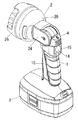
以下、本発明を添付図面に示す実施形態に基いて説明すると、図示例の携帯電灯は、電動工具用の電池パック3を電源として利用するもので、二次電池を内蔵する電池パック3が下端に着脱自在に装着される本体部1は、その上端にヘッド部2が回動自在に連結されたものとなっている。
Hereinafter, the present invention will be described based on an embodiment shown in the accompanying drawings. The portable electric light in the illustrated example uses a
上記本体部1は、図3に示すように、左右二つ割で構成されるとともにビス11で連結されるハウジング10内に、回路基板12と電池パック3との接続用の端子13とを配設したもので、回路基板12上にはオンオフ用のプッシュ型のスイッチ14が設けられており、このスイッチ14の操作部が本体部1の背面上部側に防水用ゴムキャップ15が被せられた状態で位置している。本体部1はグリップ型の形状をしており、本体部1を使用者が握った時、親指で操作することができる位置にスイッチ14が位置しているものである。
As shown in FIG. 3, the
一方、ヘッド部2はハウジング20内にソケット基板21と反射板23とを内蔵したもので、ハウジング20の左右から突出させた連結脚24を本体部1の一端にビス型の連結軸17で連結することで本体部1に対して連結軸17の軸回りに略90°の範囲(図1と図4に示す範囲)内で回動自在となるようにしたもので、本体部1の回路基板12にリード線18によって接続されるソケット基板21のソケット部にハロゲン球のような光源22が装着される。図中25はハウジング20の投光用開口部に装着される透明カバー、26は透明カバー25の固定用の固定枠、27は上記ソケット基板21の固定用のビスである。
On the other hand, the
また、本体部1内にはクリック用係合体18が配設されている。このクリック用係合体18は、本体部1に対してヘッド部2を回動させる時、ばね19による付勢を受けてヘッド部2における上記連結脚24の内面に形成した複数の被係合部(図示せず)に選択的に係合することで角度保持を行う。
A click
電池残容量の警告用の警告灯4は発光ダイオードで形成されたもので、回路基板12に接続された警告灯4は、本体部1外面における上記スイッチ14近傍で且つヘッド部2寄りのところに配置されている。
The
前記回路基板12は、電池電圧を計測して計測電圧が警告用所定値まで低下したならば上記警告灯4を点灯もしくは点滅させるとともに計測電圧が上記警告用所定値よりも更に低い遮断用所定値まで低下したならば、前記二次電池の過放電防止のために上記光源22への電流を遮断する制御回路を実装したものである。
The
しかして、該携帯電灯では電池パック3を装着した状態でスイッチ14を投入することで、光源22に電流を供給して投光を行うことができるとともに、本体部1に対してヘッド部2を回動させて向きを変えることで、投光方向と本体部1を持つ手の位置関係を変更することができるものであり、そして投光による電力消費によって電池パック3内の二次電池の電圧が低下して、前記警告用所定値まで低下した時、警告灯4の点灯乃至点滅がなされ、電池の電圧が更に低下して遮断用所定値まで達したならば光源22への電流供給が遮断されることで消灯される。
Thus, in the portable electric light, by turning on the
ここにおいて、警告灯4は親指で操作されるスイッチ14の近傍で且つスイッチ14よりもヘッド部2側のところに配されているとともに、ヘッド部2を回動させてもヘッド部2によって隠されたり陰となってしまうことがない位置にあるために、本体部1に対するヘッド部2の向きを変えるとともに使用者が携帯電灯を持つ姿勢を変えようと、スイッチ14を親指で操作することができる状態で本体部1を握っている限り、警告灯4は常に使用者側のところに位置するとともに使用者の手で隠されてしまうようなこともなく、このために使用者は警告灯4による警告を確実に認識することができる。なお、図示例では警告灯4を本体部1に設けているが、ヘッド部2に配置してもよい。
Here, the
図5に他例を示す。ここでは警告灯4を携帯電灯の外面にではなく、ヘッド部2内部の反射板23で囲まれた空間内に配置している。また、警告灯4には光源22が発する色とは異なる色の発光を行う発光ダイオードを用いている。なお、警告灯4は光源22に近い位置に配置することが好ましい。
FIG. 5 shows another example. Here, the
このものにおいては、電池電圧が低下することで警告灯4が点灯した時、この警告灯4が発する光が光源22の光とともに反射板23で反射されて投光されるものであり、この時、被照射面に照射された光には、光源22による光の他に、警告灯4による異色の色が一部に入るものであり、このために使用中である時には警告灯4が外部からは見えない位置にあるにもかかわらず、被照射面を注視する使用者にしてみれば、警告灯4の点灯を容易に認識することができる。
In this case, when the
1 本体部
2 ヘッド部
3 電池パック
4 警告灯
14 スイッチ
22 光源
DESCRIPTION OF
Claims (3)
Priority Applications (1)
| Application Number | Priority Date | Filing Date | Title |
|---|---|---|---|
| JP2005002974A JP4363329B2 (en) | 2005-01-07 | 2005-01-07 | Portable light |
Applications Claiming Priority (1)
| Application Number | Priority Date | Filing Date | Title |
|---|---|---|---|
| JP2005002974A JP4363329B2 (en) | 2005-01-07 | 2005-01-07 | Portable light |
Publications (2)
| Publication Number | Publication Date |
|---|---|
| JP2006190625A JP2006190625A (en) | 2006-07-20 |
| JP4363329B2 true JP4363329B2 (en) | 2009-11-11 |
Family
ID=36797620
Family Applications (1)
| Application Number | Title | Priority Date | Filing Date |
|---|---|---|---|
| JP2005002974A Expired - Lifetime JP4363329B2 (en) | 2005-01-07 | 2005-01-07 | Portable light |
Country Status (1)
| Country | Link |
|---|---|
| JP (1) | JP4363329B2 (en) |
Cited By (1)
| Publication number | Priority date | Publication date | Assignee | Title |
|---|---|---|---|---|
| CN104948929A (en) * | 2014-03-25 | 2015-09-30 | 日立工机株式会社 | Illuminating device |
Families Citing this family (5)
| Publication number | Priority date | Publication date | Assignee | Title |
|---|---|---|---|---|
| JP5558987B2 (en) * | 2010-09-17 | 2014-07-23 | 三洋電機株式会社 | Portable lighting |
| JP6453956B2 (en) * | 2013-06-10 | 2019-01-16 | 株式会社マキタ | Light |
| JP6200724B2 (en) * | 2013-06-10 | 2017-09-20 | 株式会社マキタ | Light |
| JP6884588B2 (en) * | 2017-02-08 | 2021-06-09 | 株式会社マキタ | Flashlight |
| WO2021106494A1 (en) * | 2019-11-28 | 2021-06-03 | 工機ホールディングス株式会社 | Electric device and electric device system |
-
2005
- 2005-01-07 JP JP2005002974A patent/JP4363329B2/en not_active Expired - Lifetime
Cited By (2)
| Publication number | Priority date | Publication date | Assignee | Title |
|---|---|---|---|---|
| CN104948929A (en) * | 2014-03-25 | 2015-09-30 | 日立工机株式会社 | Illuminating device |
| CN104948929B (en) * | 2014-03-25 | 2019-11-22 | 工机控股株式会社 | Lighting device |
Also Published As
| Publication number | Publication date |
|---|---|
| JP2006190625A (en) | 2006-07-20 |
Similar Documents
| Publication | Publication Date | Title |
|---|---|---|
| US7029142B2 (en) | Power tool | |
| JP5431366B2 (en) | Hat-mounted light emitting device | |
| US7481551B2 (en) | Flashlight having back light elements | |
| US10821595B2 (en) | Power tool | |
| CN101293343B (en) | power tool | |
| JP2014505327A (en) | Portable lighting device with reconfigurable user interface | |
| US20080144309A1 (en) | Lighted cooking utensil | |
| US20120112100A1 (en) | Bactericidal Lighting Device | |
| JP2012018923A (en) | Flashlight | |
| US20160040834A1 (en) | Rotary Head Flashlight Headlamp | |
| JP4363329B2 (en) | Portable light | |
| US7267454B2 (en) | Universal chargeable electro-optical illuminating lamp | |
| CA2817392C (en) | Illumination lamp with integrated switch and alarm | |
| US8465169B2 (en) | Driving shaft mechanism for ratchet wrench | |
| AU2011209798A1 (en) | Folding spotlight | |
| JP2512328Y2 (en) | Electric tool | |
| US20040174703A1 (en) | Flexible flashlight with LED light source | |
| JP5090229B2 (en) | Electric tool | |
| KR20120136664A (en) | Screwdriver comprising mirror assembly | |
| JP4402155B1 (en) | Ring light fixture | |
| JP5696290B2 (en) | Portable light | |
| CA2862412C (en) | Rotary head flashlight headlamp | |
| TWM552560U (en) | Life-preserving tool | |
| TWM284820U (en) | Flashlight with flexible case | |
| KR20070119185A (en) | Portable lamp |
Legal Events
| Date | Code | Title | Description |
|---|---|---|---|
| A621 | Written request for application examination |
Free format text: JAPANESE INTERMEDIATE CODE: A621 Effective date: 20061213 |
|
| A977 | Report on retrieval |
Free format text: JAPANESE INTERMEDIATE CODE: A971007 Effective date: 20090313 |
|
| A131 | Notification of reasons for refusal |
Free format text: JAPANESE INTERMEDIATE CODE: A131 Effective date: 20090428 |
|
| A521 | Written amendment |
Free format text: JAPANESE INTERMEDIATE CODE: A523 Effective date: 20090629 |
|
| TRDD | Decision of grant or rejection written | ||
| A01 | Written decision to grant a patent or to grant a registration (utility model) |
Free format text: JAPANESE INTERMEDIATE CODE: A01 Effective date: 20090728 |
|
| A01 | Written decision to grant a patent or to grant a registration (utility model) |
Free format text: JAPANESE INTERMEDIATE CODE: A01 |
|
| A61 | First payment of annual fees (during grant procedure) |
Free format text: JAPANESE INTERMEDIATE CODE: A61 Effective date: 20090810 |
|
| FPAY | Renewal fee payment (event date is renewal date of database) |
Free format text: PAYMENT UNTIL: 20120828 Year of fee payment: 3 |
|
| R151 | Written notification of patent or utility model registration |
Ref document number: 4363329 Country of ref document: JP Free format text: JAPANESE INTERMEDIATE CODE: R151 |
|
| FPAY | Renewal fee payment (event date is renewal date of database) |
Free format text: PAYMENT UNTIL: 20130828 Year of fee payment: 4 |