JP4360593B2 - Hinge structure and mobile information terminal device - Google Patents
Hinge structure and mobile information terminal device Download PDFInfo
- Publication number
- JP4360593B2 JP4360593B2 JP2002039092A JP2002039092A JP4360593B2 JP 4360593 B2 JP4360593 B2 JP 4360593B2 JP 2002039092 A JP2002039092 A JP 2002039092A JP 2002039092 A JP2002039092 A JP 2002039092A JP 4360593 B2 JP4360593 B2 JP 4360593B2
- Authority
- JP
- Japan
- Prior art keywords
- hinge structure
- case body
- fitting
- action
- state
- Prior art date
- Legal status (The legal status is an assumption and is not a legal conclusion. Google has not performed a legal analysis and makes no representation as to the accuracy of the status listed.)
- Expired - Fee Related
Links
Images


Classifications
-
- H—ELECTRICITY
- H04—ELECTRIC COMMUNICATION TECHNIQUE
- H04M—TELEPHONIC COMMUNICATION
- H04M1/00—Substation equipment, e.g. for use by subscribers
- H04M1/02—Constructional features of telephone sets
- H04M1/0202—Portable telephone sets, e.g. cordless phones, mobile phones or bar type handsets
- H04M1/0206—Portable telephones comprising a plurality of mechanically joined movable body parts, e.g. hinged housings
- H04M1/0208—Portable telephones comprising a plurality of mechanically joined movable body parts, e.g. hinged housings characterized by the relative motions of the body parts
- H04M1/0225—Rotatable telephones, i.e. the body parts pivoting to an open position around an axis perpendicular to the plane they define in closed position
- H04M1/0227—Rotatable in one plane, i.e. using a one degree of freedom hinge
Landscapes
- Engineering & Computer Science (AREA)
- Signal Processing (AREA)
- Pivots And Pivotal Connections (AREA)
- Telephone Set Structure (AREA)
Description
【0001】
【発明が属する技術分野】
本発明は、第1の部材と第2の部材とを互いに回動自在に支持するヒンジ構造及びこれを用いた折り畳み可能なモバイル情報端末機器、たとえば、携帯電話機に関し、所定の開き角以上に開こうとする外力がかかったときでも、ヒンジ構造を構成する部材やこれの近傍に配置され開き角を規制している部材などが破損することがないようにする技術に関する。
【0002】
【従来の技術】
従来、携帯電話機等のモバイル情報端末機器において、主に操作キーが設けられた操作ケース体と主に表示部が設けられた表示ケース体とをヒンジ構造を介して折り畳み自在にしたものがある。
【0003】
このような折り畳み型携帯電話機のタイプとして、ヒンジ軸が操作面及び表示面に対して直交する方向に配置された折り畳み型携帯電話機(以下、「ジャックナイフ型携帯電話機」という。)と、ヒンジ軸が操作面及び表示面に対して平行に配置された折り畳み型携帯電話機(以下、「通常の折り畳み携帯電話機」という。)とがある。
【0004】
いずれの折り畳み型携帯電話機においても、通話時には2つのケース体を開放状態にして使用し、非通話時には2つのケース体を折り畳むことができ、携帯性に優れている。
【0005】
【課題を解決するための手段】
ところが、このような折り畳み型携帯電話機にあっては、2つのケース体の開き角度が予め設定されており、その開く角度よりも開く方向に外力がかかってしまうと、ヒンジ部やその開き角を規制している部材が破損してしまうという問題がある。
【0006】
尚、ジャックナイフ型携帯電話機の場合は、操作ケース体に対して表示ケース体を360°以上回転するように設計することもできるが、このようにすると、2つのケース体内の電子部品を接続するケーブルが捻れてしまうため、通常、0°〜180°の開き角の範囲で2つのケース体を往復させるようにしている。
【0007】
そして、折り畳み型携帯電話機は、所定角度以上に2つのケース体が開かないようにするために、例えば、ヒンジ構造の第1の部材と第2の部材とを当接させたり、或いは表示ケース体と操作ケース体とを当接させることにより、機械的に両ケース体の一部又は一部分が接触又は当接してその回動を阻止するようになっている。
【0008】
ところが、勢いよく開放したり、或いは開放した状態でさらに開く方向に外力がかかってしまうことがある。
【0009】
具体的には、上述のいわゆるジャックナイフ型携帯電話機にあっては、操作ケース体に対して表示ケース体を勢いよく開放してしまうことがある。
【0010】
また、通常の折り畳み携帯電話機にあっては、操作面及び表示面を開いた状態で、これら操作面及び表示面を下にして置いてしまったときに、上方からヒンジ部分に何らかの外力がかかってしまうと、いわゆるサバ折り状態になってしまう。
【0011】
そして、2つのケース体が必要以上に開放されようとすると、上記したヒンジ構造の第1の部材、第2の部材、或いは表示ケース体、操作ケース体の一部に負荷がかかり、該部位を破損してしまうことになる。
【0012】
そこで、本発明ヒンジ構造及びモバイル情報端末機器は、所定開き角度よりもさらに開く方向に外力がかかったときでも、その外力を吸収することで、ヒンジ構造を形成する部材、或いはこれらの近傍に配置された他の部材に負荷がかからないようにし、部品又は部材の破損を防止することを課題とする。
【0013】
【課題を解決するための手段】
そして、本発明ヒンジ構造は、上記した課題を解決するために、第1の部材と第2の部材とを互いに回動自在に支持するヒンジ構造であって、第1の部材には嵌合凸部又は嵌合凹部が形成され、第2の部材には嵌合凹部又は嵌合凸部が形成され、上記嵌合凸部と嵌合凹部との嵌合により、第1の部材と第2の部材とが互いに回動自在にされ、第1の部材と第2の部材との間には少なくとも回動方向に対して弾性を有する弾性部材が介在され、該弾性部材は2つの作用部を有し、一方の作用部は上記第1の部材にその回動方向への移動が許容された状態で支持され、また、他方の作用部は上記第2の部材にその回動方向への移動が規制された状態で支持されており、第1の部材には、第2の部材に対する回動に伴う上記弾性部材の一方の作用部の上記移動を所定角度で許容する移動許容空間が形成され、上記弾性部材は第1の部材と第2の部材が互いに離間する方向に対しても弾性を有し、また、弾性部材の上記2つの作用部には、折曲部がそれぞれ形成され、第1の部材及び第2の部材には、上記作用部の折曲部を両部材が離間する方向に対して係止する係止部がそれぞれ形成されているものである。
【0014】
また、本発明モバイル情報端末機器は、上記した課題を解決するために、主操作キーが設けられた操作ケース体と、表示部が設けられた表示ケース体とを有し、操作ケース体と表示ケース体とが、ヒンジ構造を介して回動自在に支持されたモバイル情報端末機器であって、上記ヒンジ構造は、第1の部材と第2の部材とを互いに回動自在に支持するヒンジ構造であり、第1の部材には嵌合凸部又は嵌合凹部が形成され、第2の部材には嵌合凹部又は嵌合凸部が形成され、上記嵌合凸部と嵌合凹部との嵌合により、第1の部材と第2の部材とが互いに回動自在にされ、第1の部材と第2の部材との間には少なくとも回動方向に対して弾性を有する弾性部材が介在され、該弾性部材は2つの作用部を有し、一方の作用部は上記第1の部材にその回動方向への移動が許容された状態で支持され、また、他方の作用部は上記第2の部材にその回動方向への移動が規制された状態で支持されており、第1の部材には、第2の部材に対する回動に伴う上記弾性部材の一方の作用部の上記移動を所定角度で許容する移動許容空間が形成されており、上記第1の部材が上記操作ケース体又は表示ケース体に、また、上記第2の部材が上記表示ケース体又は操作ケース体にそれぞれ取着され、上記ヒンジ構造の弾性部材は第1の部材と第2の部材が互いに離間する方向に対しても弾性を有し、また、弾性部材の上記2つの作用部には、折曲部がそれぞれ形成され、第1の部材及び第2の部材には、上記作用部の折曲部を両部材が離間する方向に対して係止する係止部がそれぞれ形成されているものである。
【0015】
従って、本発明にあっては、移動許容空間の範囲内での第1の部材と第2の部材との回動においては、抵抗となるものがないためその移動を許容し、所望する角度で回動させることができ、所定の角度を超える回動力が働いたときに、上記弾性部材が作用して、その回動力を吸収する。
【0016】
【発明の実施の形態】
以下に、本発明の各実施の形態を添付図面を参照して説明する。
【0017】
図1乃至図23に示したものは、本発明の第1の実施の形態であり、いわゆるジャックナイフ型携帯電話機に適用したものである。
【0018】
先ず、図1乃至図3に第1の実施の形態にかかる携帯電話機の概要について説明する。
【0019】
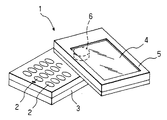
携帯電話機1は、主として操作キー等の操作釦2、2、・・・が設けられた操作ケース体3と液晶表示パネル4が設けられた表示ケース体5とがヒンジ構造6を介して、面方向に折り畳み自在に結合されている。
【0020】
携帯電話機1を用いて通話を行わないときには、操作ケース体3の上記操作釦2、2、・・・が設けられた面が表示ケース体5によって覆われており、閉塞状態とされている(図1参照)。閉塞状態においては、表示ケース体5は、その液晶表示パネル4が設けられた面が表側に位置し、その反側の面が上記操作ケース体3の操作釦2、2、・・・が設けられた面に接した状態又は近接した状態とされている(図1参照)。
【0021】
携帯電話機1を用いて通話を行うときには、操作ケース体3又は表示ケース体5を表示ケース体5又は操作ケース体3に対してヒンジ構造6の軸回り方向へ回転し(図2参照)、開放状態とする(図3参照)。
【0022】
このように、開放状態において、操作ケース体3の操作釦2、2、・・・が露出され、その操作が可能となる(図3参照)。
【0023】
次に、上記携帯電話機1に用いられたヒンジ構造6について説明する(図4乃至図23参照)。
【0024】
上記ヒンジ構造6は、上記表示ケース体5に取着される表示ケース側部材7と、上記操作ケース体に取着される操作ケース側部材8と、これら表示ケース側部材7と操作ケース側部材8との間に介在された弾性部材としてのコイルバネ9とから成る(図5参照)。尚、上記表示ケース側部材7は特許請求の範囲に記載した「第1の部材」に、操作ケース側部材8が特許請求の範囲に記載した「第2の部材」に相当する。
【0025】
表示ケース側部材7は、円筒状をした嵌合凸部10とその上端に形成されたフランジ部11とが一体に形成されて成る(図11、図12他参照)。
【0026】
嵌合凸部10の下端縁(先端縁)はR面10aに形成されており、上記操作ケース側部材8の後述する嵌合凹部に内嵌しやすくなっている(図23参照)。尚、このR面10aは特許請求の範囲に記載した「曲面」に相当する。
【0027】
操作ケース側部材8は、上記嵌合凸部10より一回り大きな円筒体12と、該円筒体12の下端に形成されたフランジ部13とが一体に形成されて成る(図11、図12他参照)。
【0028】
上記円筒体12の内径は、上記嵌合凸部10の外径とほぼ同じか又は僅かに大きく形成されており、この内側の孔(以下、「貫通孔」という。)12aの上側部分が上記嵌合凸部10が内嵌する嵌合凹部14となっている(図11、図12他参照)。
【0029】
そして、表示ケース側部材7の嵌合凸部10が操作ケース側部材8の嵌合凹部14に嵌合されることにより、表示ケース側部材7に対して操作ケース側部材8が回動自在に支持される(図11、図12他参照)。
【0030】
また、表示ケース側部材7の嵌合凸部10には、そのほぼ中心に貫通孔が10bが形成されており、表示ケース側部材7の嵌合凸部10と操作ケース側部材8の嵌合凹部14との嵌合により、嵌合凸部10の貫通孔10bと円筒体12の貫通孔12aとが連通される(図11、図12他参照)。
【0031】
これにより、表示ケース側部材7の内部の電子部品(図示は省略する。)と操作ケース側部材8の内部の電子部品(図示は省略する。)とを電気的接続するケーブル15を、上記連通された2つの貫通孔10b、12a内に挿通することができるようになっている(図11、図12他参照)。
【0032】
表示ケース側部材7のフランジ部11には、その外周縁よりやや中心に寄った位置に中心角で220°の円弧状溝16が形成されており、該円弧状溝16はフランジ部11の上面と下面とに達するように形成されている(図4、図5他参照)。
【0033】
また、円弧状溝16の上面側であってその外周側縁にはフランジ部11の上面側部分の肉厚を切除して形成された棚部17が形成されている。そして、該棚部17も上記円弧状溝16と同じ中心角220°で形成されており、円弧状溝16と棚部17とで、断面形状が逆L字状で中心角220°の空間(以下、「移動許容空間」という。)が形成される。かかる移動許容空間18は、後述するようにコイルバネ9の一方の作用部が周方向に移動できる空間として機能する(図4、図5他参照)。
【0034】
また、上記棚部17はコイルバネ9の後述する一方の作用部に形成された折曲部を引っ掛けて、これを下方へ移動しないようにするための係止部として機能する(図11、図12他参照)。
【0035】
表示ケース側部材7のフランジ部11の下面であって、上記嵌合凸部10に近接した位置には、中心角90°の間隔で等間隔に4つのダボ19、19、・・・が垂設するように形成されている。また、ダボ19の下端面はR面に形成されており、これにより、操作ケース側部材8に形成された後述する小凹部に対する嵌合又は離脱を容易にすることができるようになっている(図11、図12他参照)。
【0036】
表示ケース側部材7のフランジ部11の中心角180°離間した外周面には互いに反対方向に突出する取付片20、20が一体に形成されており、該取付片20、20にはネジ挿通孔21、21が形成されている(図4、図5他参照)。
【0037】
操作ケース側部材8の上記円筒体12の上端面には、上記ダボ19、19、・・・が各別に嵌合する小凹部22、22、・・・が中心角90°の間隔で等間隔に形成されている(図6、図7他参照)。尚、上記ダボ19、19、・・・と小凹部22、22、・・・との嵌合する位置は、上記移動許容空間18内におけるコイルバネ9の後述する一方の作用部の位置とに関係する。
【0038】
操作ケース側部材8のフランジ部13には、その外周縁よりやや中心に寄った位置に上下に貫通する挿通孔23が形成されており、該挿通孔23の下面側にはフランジ部13の下面側部分の肉厚を切除して引掛部24が形成されている。該引掛部24はコイルバネ9の後述する他方の作用部に形成された折曲部を引っ掛けてこれを上方へ移動しないようにするための係止部として機能する(図12参照)。
【0039】
操作ケース側部材8のフランジ部13の中心角180°離間した外周面には互いに反対方向に突出する取付片25、25が一体に形成されており、該取付片25、25にはネジ挿通孔26、26が形成されている(図4、図5他参照)。
【0040】
コイルバネ9は、操作ケース側部材8の円筒体12の外径より一回り大きな径に巻回されたコイル部27と、該コイル部27の一端に軸方向と平行で上方に折り曲げられた作用部28と、コイル部27の他端に軸方向と平行で下方に折り曲げられた作用部29とから成る(図5参照)。
【0041】
コイルバネ9のコイル部27は中心角でほぼ450°、すなわち、一回りと1/4巻分、巻回されている(図5参照)。尚、コイル部27の巻数はこれに限定されるものでなく、2巻、3巻など適宜、設定することができる。
【0042】
コイルバネ9の一方の作用部28の先端はさらに外方に折り曲げられて折曲部28aが形成され、他方の作用部29の先端もさらに外方に折り曲げられて折曲部29aが形成されている(図5参照)。
【0043】
このように形成されたコイルバネ9は、次のように表示ケース側部材7と操作ケース側部材8とに組み付けられる(図5参照)。
【0044】
すなわち、まず、表示ケース側部材7と操作ケース側部材8とが嵌合凸部10と嵌合凹部14との嵌合により回動自在にされ、この状態の両部材7、8にコイルバネ9を組み付ける(図4参照)。
【0045】
コイルバネ9は、そのコイル部27が操作ケース側部材8の円筒体12に外嵌され、その一方の作用部28が表示ケース側部材7の円弧状溝16に挿通され、かつ、その折曲部28aが棚部17に載置された状態にされ、また、他方の作用部29が操作ケース側部材8の挿通孔23に挿通され、かつ、その折曲部29aが引掛部24に位置される(図12参照)。
【0046】
これにより、表示ケース側部材7と操作ケース側部材8とは、コイルバネ9の2つの折曲部28a及び29aが棚部17又は引掛部24にそれぞれ係止されるため、両部材7と8とを軸方向で密着する方向に力がかかり、両部材7と8とが離脱しないようになっている(図23参照)。
【0047】
また、上述のように、円弧状溝16に連続する棚部17を形成したので、コイルバネ9の一方の作用部28の折曲部28aが移動許容空間18内を摺動するとき、折曲部28aがフランジ部11の上面に突出することがないため、当該ヒンジ構造6の近傍に配置される他の部材、部品などと干渉することがなく、その分、他の部材、部品をヒンジ構造6に近接して配置することができ、装置全体の小型化に貢献する(図4参照)。
【0048】
操作ケース側部材8に対して表示ケース側部材7が回動するとき、上記ダボ19、19、・・・が操作ケース側部材8の円筒体12の端面に形成された小凹部22、22、・・・に各別に嵌合又は離間を繰り返すことになり、ダボ19、19、・・・と小凹部22、22、・・・とが嵌合した状態で、表示ケース側部材7と操作ケース側部材8との周方向における位置決めが為された状態となる。尚、ダボ19、19、・・・と小凹部22、22、・・・とは、特許請求の範囲に記載した「凹凸嵌合部」に相当する。
【0049】
そして、ダボ19、19、・・・と小凹部22、22、・・・の凹凸嵌合部は、ダボ19、19、・・・及び小凹部22、22、・・・が周方向の等間隔に4つ形成したので、表示ケース側部材7と操作ケース側部材8とを回動角(開き角)90°毎に嵌合させて位置決めされる(図10、図16、図18参照)。
【0050】
これにより、後述するように、表示ケース側部材7と操作ケース側部材8とを閉じた状態(0°状態)と開いた状態(180°状態)とで位置決めすることができる。
【0051】
ダボ19、19、・・・が小凹部22、22、・・・から離間するとき、表示ケース側部材7と操作ケース側部材8とが離間する方向へ移動することになるが、上述のようにコイルバネ9により、両部材7と8とが離脱することはない。
【0052】
また、上述のように、コイルバネ9の一方の作用部28が表示ケース側部材7の円弧状溝16内に位置されているため、表示ケース側部材7を操作ケース側部材8に対して回動させたときに、上記一方の作用部28が円弧状溝16内を摺動する(図10、図13、図16、図18、図20参照)。
【0053】
そして、コイルバネ9の一方の作用部28が円弧状溝16の周方向の端部に接触するまで移動すると(図13、図20参照)、作用部28の円弧状溝16内での摺動は阻止される。尚、作用部28が円弧状溝16内を摺動している状態においては、コイルバネ9には外力が働かず、よって、コイルバネ9には弾発力が蓄積されない。
【0054】
さらに、表示ケース側部材7の同じ方向への回動が為されると、作用部28がその移動が阻止された状態であるため、コイルバネ9が弾性変形を起こし、弾発力が発生する。
【0055】
また、上記ダボ19、19、・・・と小凹部22、22、・・・との嵌合する位置と、上記移動許容空間18内における一方の作用部28の位置との関係は、作用部28が移動許容空間18の両端部に当接するほぼ20°前の状態において、ダボ19、19、・・・と小凹部22、22、・・・とが嵌合するようになっている。従って、ダボ19、19、・・・と小凹部22、22、・・・とが嵌合するのは、移動許容空間18の両端部からそれぞれ20°手前の2ヶ所及び移動許容空間18の中央部の計3ヶ所となっている(図10、図16、図18参照)。
【0056】
尚、このようにダボ19と小凹部22との嵌合が為された後、さらに回動されたときに、移動許容空間18の端部に作用部28が当接するようにしたのは、ダボ19と小凹部22との嵌合と、作用部28の移動許容空間18の端部との当接とを同じタイミングで行おうとすると、各部の寸法精度を高くしなければならないからである。これにより、各部の寸法精度をラフにすることができる。
【0057】
このように形成されたヒンジ構造6は、次のようにして携帯電話機1の操作ケース体3と表示ケース体5とに組み付けられる(図8、図9参照)。
【0058】
まず、操作ケース体3の上記操作釦2、2、・・・が設けられた面の一端にヒンジ体配設孔が形成され、また、表示ケース体5の上記液晶表示パネル4が設けられた面と反対側の面の一端にヒンジ体配置孔30、31がそれぞれ形成されている(図8、図9参照)。
【0059】
これらヒンジ体配置孔30、31は、ヒンジ構造6の2つのフランジ部11及び13が挿通できる大きさのほぼ円形をし、また、上記取付片20、20、25、25に対応した位置に、これら取付片が挿入できる切欠部32、32、・・・が形成されている(図8、図9参照)。
【0060】
そして、このようなヒンジ体配置孔30、31に上記ヒンジ構造6をそれぞれ内嵌する。このとき、上記切欠部32、32、・・・に合わせて取付片20、20、25、25の向きを変える。
【0061】
次に、操作ケース体3の上面内側にネジ33、33を介してヒンジ構造6の操作ケース側部材8の取付片25、25を取り付ける。
【0062】
他方、表示ケース体5に対しても、上記操作ケース体3への取り付け方とほぼ同じようにしてヒンジ構造6の表示ケース側部材7の取付片20、20をネジ33、33を介して取り付ける(図8参照)。
【0063】
これにより、ヒンジ構造6は操作ケース体3と表示ケース体5とを回動自在に結合することになる(図8参照)。
【0064】
尚、操作ケース体3と表示ケース体5とを結合したヒンジ構造6の表示ケース側部材7及び操作ケース側部材8と各ケース体3、5との位置関係は、次のようになっている。
【0065】
まず、操作ケース体3と表示ケース体5とを開放した状態(通話可能状態)にあっては、表示ケース側部材7のダボ19、19、・・・と操作ケース側部材8の小凹部22、22、・・・とが嵌合した状態で、コイルバネ9の一方の作用部28が表示ケース側部材7の移動許容空間18の時計回り方向の端部と接触する位置より中心角でほぼ20°手前の状態になっている(図10、図11、図12参照)。尚、この状態を「180°状態」という。
【0066】
この180°状態から表示ケース体5を時計回り方向と反対方向(以下、「反時計回り方向」という。)にほぼ20°回動させると、コイルバネ9の一方の作用部28が移動許容空間18における時計回り方向の端部に衝突する(図13、図14参照)。この状態を「200°状態」という。
【0067】
この200°状態までは、コイルバネ9には外力がかかっておらず、弾発力が発生していない状態であるが、これ以上に表示ケース体5が回動されると、コイルバネ9の一方の作用部28が移動許容空間18の時計回り方向の端部にその移動を阻止されているため、コイルバネ9に弾発力が発生する。
【0068】
このような状態は、通常、2つのケース体3、5が閉塞状態から勢い良く開放したときに、180°状態(開放状態)を行き過ぎてしまったときに起こるが、この実施の形態にかかる携帯電話機1にあっては、200°状態まで回動できること及びそれ以上の回動があっても、その回動力をコイルバネ9が変形することにより緩衝するため、他の部材等が破損することを防止することができる。
【0069】
次に180°状態から表示ケース体5を閉塞方向に、すなわち、時計回り方向にほぼ90°回動させると、上記ダボ19、19、・・・と小凹部22、22、・・・との嵌合がなされる(図16、図17参照)。この状態を「90°状態」という。
【0070】
さらに、90°状態から表示ケース体5を閉塞方向に、ほぼ90°回動させると、上記ダボ19、19、・・・と小凹部22、22、・・・との嵌合が外れた後、再び、ダボ19、19、・・・と小凹部22、22、・・・との嵌合がなされる(図18、図19参照)。この状態を「0°状態」といい、2つのケース体3、5を閉塞した状態である。
【0071】
0°状態から、さらに表示ケース体5を時計回り方向にほぼ20°回動させると、コイルバネ9の他方の作用部29が移動許容空間18における反時計回り方向の端部に衝突する(図20、図21参照)。この状態を「−20°状態」という。
【0072】
この−20°状態までは、コイルバネ9には外力がかかっておらず、弾発力が発生していない状態であるが、これ以上に表示ケース体5が回動されると、コイルバネ9の他方の作用部29が移動許容空間18の反時計回り方向の端部にその移動を阻止されているため、コイルバネ9に弾発力が発生する。
【0073】
このような状態は、通常、2つのケース体3、5が開放状態から勢い良く閉塞したときに、0°状態(閉塞状態)を行き過ぎてしまったときに起こるが、この実施の形態にかかる携帯電話機1にあっては、−20°状態まで回動できること及びそれ以上の回動があっても、その回動力をコイルバネ9が変形することにより緩衝するため、他の部材等が破損することを防止することができる。
【0074】
以上のように、上記携帯電話機1にあっては、2つのケース体3、5を勢い良く回動して、開放状態(180°状態)や閉塞状態(0°状態)を行き過ぎてしまっても、上記コイルバネ9が回転方向に対して弾性を有するため、上記行き過ぎた回動力を吸収することになり、他の部材が破損することを防止することができる。
【0075】
また、上記第1の実施の形態にかかる携帯電話機1にあっては、180°状態(開放状態)の2つのケース体3、5を上記ヒンジ構造6の回動軸を傾動する方向に外力が掛かった場合について説明する。すなわち、180°状態において2つのケース体3、5がサバ折り状態になった場合である(図22、図23参照)。
【0076】
たとえば、180°状態の携帯電話機1を操作釦2、2、・・・及び液晶表示パネル4が上方を向く向きで置いたときに、表示ケース体5の回動端側の端部に上方からの外力が加わると、表示ケース体5の下面が操作ケース体3の端縁に引っかかり、上記ヒンジ体の表示ケース側部材7と操作ケース側部材8とが離間する方向に力が加わる(図23参照)。
【0077】
そして、上記両ケース側部材7と8とが離間しようとすると、上記コイルバネ9の2つの作用部28、29の折曲部28a、29aがそれぞれ棚部17又は引掛部24に係止されているため、コイルバネ9のコイル部27が軸方向に広がろうとして、コイルバネ9がいわゆるトーションバネとして機能する。
【0078】
そして、コイルバネ9はこれに抗するように弾発力が発生し、サバ折りしようとする上記外力を吸収することになる。
【0079】
従って、上記第1の実施の形態にかかる携帯電話機1にあっては、そのヒンジ構造6が回動方向に対しても、また、軸方向にも、弾性を有するので、そのいずれの方向からの外力に対してもこれを吸収することができ、各部の破損を防ぐことができる。
【0080】
図24及び図25は、上記凹凸嵌合部(ダボ19と小凹部22)の変形例を示すものである。
【0081】
この変形例にかかる複数の凹凸嵌合部45が表示ケース側部材7と操作ケース側部材8との摺動面に小歯状の凹凸部を連続して形成したものである。
【0082】
これにより、表示ケース側部材7と操作ケース側部材8と周方向においてきめ細かな位置決めをすることができる。
【0083】
図26に示したものは、本発明携帯電話機の第2の実施の形態を示すもので、通常の折り畳み携帯電話機に適用したものである。
【0084】
携帯電話機1Aは、表示ケース体40と操作ケース体41とがヒンジ軸に対して直交する方向に回動自在にされている。
【0085】
表示ケース体40の一端部に該表示ケース体40のほぼ半分の幅を有するヒンジ筒体42形成され、また、操作ケース体41の一端部に該操作ケース体41のほぼ半分の幅を有するヒンジ筒体43が形成されている。
【0086】
そして、2つのヒンジ筒体42、43は同軸状に合わさるようにしてヒンジ構造6Aを介して連結されている。
【0087】
このように、連結された表示ケース体40と操作ケース体41とは、所定角度で開かれ、それ以上の開放方向への外力がかかった場合、上述のヒンジ構造6Aと同様に、弾性部材の弾性により上記外力が吸収され、ヒンジ構造6Aを構成する部材、或いは表示ケース体40及び操作ケース体41の一部を破損することはない。
【0088】
さらに、この第2の実施の形態にかかる携帯電話機1Aにあっては、操作ケース体41側のヒンジ筒体43の外側端部に、CCDカメラ44がヒンジ構造6Aを介して回動自在に支持されている。尚、図面ではCCDカメラ44を携帯電話機1Aから離間させた状態に示しているが、これはヒンジ構造6Aを示すための便宜的処置であって、実際には、CCDカメラ44はヒンジ構造6Aを介して操作ケース体41のヒンジ筒体43に結合されている。
【0089】
そして、CCDカメラ44に上記ヒンジ構造の第1の部材又は第2の部材が取着され、ヒンジ筒体43に第2の部材又は第1の部材が取着される。
【0090】
このように操作ケース体にヒンジ構造6Aを介して取着されたCCDカメラ44は、操作ケース体41に対して所定角度回動自在に支持され、また、ヒンジ軸に対して直交する方向での外力がかかったときでも、上述の弾性部材(コイルバネ9)によりその外力を吸収することができる。
【0091】
尚、上記した各実施の形態においては、本発明を携帯電話機に適用したものを示したが、本発明の適用範囲が携帯電話機に限定されることを意味するものではなく、ヒンジ機構によって互いに回動可能に連結された2つの部分を有するモバイル情報端末機器であれば広く適用することが可能である。
【0092】
また、上記実施の形態にかかるヒンジ構造にあっては、弾性部材としてコイルバネを示したが、本発明はこれに限らず、第1の部材と第2の部材との回動方向及び回動軸方向(2方向)における移動に対して弾性を有するようにしたが、本発明はこれに限らず、回転方向(1方向)に対して弾性を有する弾性部材であっても良い。かかる場合、第1の部材と第2の部材との間に、両部材が離間しないようにする手段(軸方向の抜けの防止手段)、例えば、係止爪と円弧状溝を各部材に形成し、係止爪を円弧状溝に挿通させ、係止爪の爪部の円弧状溝の縁部に引っかかるようにし、係止爪の胴部が溝内を摺動するようにすることが考えられる。
【0093】
このほか、上記した実施の形態において示した各部の形状乃至構造は、何れも本発明を実施するに際して行う具体化のほんの一例を示したものにすぎず、これらによって、本発明の技術的範囲が限定的に解釈されるようなことがあってはならないものである。
【0094】
【発明の効果】
以上に記載したところから明らかなように、本発明ヒンジ構造は、第1の部材と第2の部材とを互いに回動自在に支持するヒンジ構造であって、第1の部材には嵌合凸部又は嵌合凹部が形成され、第2の部材には嵌合凹部又は嵌合凸部が形成され、上記嵌合凸部と嵌合凹部との嵌合により、第1の部材と第2の部材とが互いに回動自在にされ、第1の部材と第2の部材との間には少なくとも回動方向に対して弾性を有する弾性部材が介在され、該弾性部材は2つの作用部を有し、一方の作用部は上記第1の部材にその回動方向への移動が許容された状態で支持され、また、他方の作用部は上記第2の部材にその回動方向への移動が規制された状態で支持されており、第1の部材には、第2の部材に対する回動に伴う上記弾性部材の一方の作用部の上記移動を所定角度で許容する移動許容空間が形成され、上記弾性部材は第1の部材と第2の部材が互いに離間する方向に対しても弾性を有し、また、弾性部材の上記2つの作用部には、折曲部がそれぞれ形成され、第1の部材及び第2の部材には、上記作用部の折曲部を両部材が離間する方向に対して係止する係止部がそれぞれ形成されていることを特徴とする。
【0095】
また、本発明モバイル情報端末機器にあっては、主操作キーが設けられた操作ケース体と、表示部が設けられた表示ケース体とを有し、操作ケース体と表示ケース体とが、ヒンジ構造を介して回動自在に支持されたモバイル情報端末機器であって、上記ヒンジ構造は、第1の部材と第2の部材とを互いに回動自在に支持するヒンジ構造であり、第1の部材には嵌合凸部又は嵌合凹部が形成され、第2の部材には嵌合凹部又は嵌合凸部が形成され、上記嵌合凸部と嵌合凹部との嵌合により、第1の部材と第2の部材とが互いに回動自在にされ、第1の部材と第2の部材との間には少なくとも回動方向に対して弾性を有する弾性部材が介在され、該弾性部材は2つの作用部を有し、一方の作用部は上記第1の部材にその回動方向への移動が許容された状態で支持され、また、他方の作用部は上記第2の部材にその回動方向への移動が規制された状態で支持されており、第1の部材には、第2の部材に対する回動に伴う上記弾性部材の一方の作用部の上記移動を所定角度で許容する移動許容空間が形成されており、上記第1の部材が上記操作ケース体又は表示ケース体に、また、上記第2の部材が上記表示ケース体又は操作ケース体にそれぞれ取着され、上記ヒンジ構造の弾性部材は第1の部材と第2の部材が互いに離間する方向に対しても弾性を有し、また、弾性部材の上記2つの作用部には、折曲部がそれぞれ形成され、第1の部材及び第2の部材には、上記作用部の折曲部を両部材が離間する方向に対して係止する係止部がそれぞれ形成されていることを特徴とする。
【0096】
従って、本発明にあっては、移動許容空間の範囲内での第1の部材と第2の部材との回動においては、抵抗となるものがないためその移動を許容し、所望する角度で回動させることができ、所定の角度を超える回動力が働いたときに、上記弾性部材が作用して、その回動力を吸収する。
【0097】
そのため、従来、他の部材が接触、当接や圧接などにより受け止めており、接触、当接などしていた部材、部品の破損を余儀なくしていたが、弾性部材により必要以上の回動力を受け止めるため、ヒンジ構造を構成する部材、部品或いはこれらの近傍に配置された他の部材、部品に負荷がかからないようにし、これら部材又は部品の破損を防止することができる。また、弾性部材は第1の部材と第2の部材が互いに離間する方向に対しても弾性を有し、また、弾性部材の上記2つの作用部には、折曲部がそれぞれ形成され、第1の部材及び第2の部材に、上記作用部の折曲部を両部材が離間する方向に対して係止する係止部をそれぞれ設けたので、2つの部材の軸方向の抜けを防止でき、軸方向の抜け防止手段を別途設ける必要はない。また、2つの部材にこれらが、離間する方向に力が働いたときに、これを防止でき、両部材の軸方向の抜けを防止できる。
【0101】
請求項2に記載した発明にあっては、上記第1の部材と第2の部材とに、回動軸に対して直交し、互いに摺接する摺接面をそれぞれ形成し、これら摺接面に回動軸の周り方向における第1の部材と第2の部材との位置決めを行う凹凸嵌合部を形成したので、第1の部材と第2の部材とが取り付けられたもの同士の位置関係を固定することができ、そのものも使い勝手を良好にする。
【0102】
また、第1の部材と第2の部材との本来の回動範囲中においても、その回動力に抵抗を与え、これを和らげることができ、必要以上の回動力がかかったときでも、上記凹凸嵌合部の嵌合により未然に緩和することができ、部材、部品の保護に貢献する。
【0103】
請求項3に記載した発明にあっては、上記嵌合凸部の先端縁を曲面に形成したので、嵌合凸部が嵌合凹部から離脱して上記弾性部材の弾発力で復帰するときに、引っ掛かる部分がなく、その復帰を容易にする。
【図面の簡単な説明】
【図1】図2及び図3と共に、本発明をいわゆるジャックナイフ型携帯電話機に適用した第1の実施の形態を示すものであり、本図は操作ケース体と表示ケース体とを閉塞した状態を示す斜視図である。
【図2】表示ケース体を操作ケース体に対して回動させている状態を示す斜視図である。
【図3】操作ケース体と表示ケース体とを開放した状態を示す斜視図である。
【図4】図5乃至図7と共に、本発明ヒンジ構造を示すものであり、本図は全体を見せる斜視図である。
【図5】分解した状態を示す斜視図である。
【図6】表示ケース側部材(第1の部材)の底面図である。
【図7】操作ケース側部材(第2の部材)の平面図である。
【図8】図9と共に、ヒンジ構造を携帯電話機のヒンジ構造に適用したものを示し、本図は組み付けた状態を示す斜視図である。
【図9】携帯電話機の各ケース体とヒンジ構造とを分離して示した斜視図である。
【図10】図11乃至図23と共に、ヒンジ構造を携帯電話機に組み付けた状態を示すもので、本図は180°状態(開放状態)のヒンジ構造を示す拡大平面図である。
【図11】図10のXI−XI線に沿う断面図である。
【図12】図10のXII−XII線に沿う断面図である。
【図13】図14及び図15と共に、200°状態を示すもので、本図はヒンジ構造を示す拡大平面図である。
【図14】図13のXIV−XIV線に沿う断面図である。
【図15】携帯電話機の斜視図である。
【図16】図17と共に、90°状態を示すもので、本図はヒンジ構造を示す拡大平面図である。
【図17】図16のXVII−XVII線に沿う断面図である。
【図18】図19と共に、0°状態(閉塞状態)を示すもので、本図はヒンジ構造を示す拡大平面図である。
【図19】図18のXIX−XIX線に沿う断面図である。
【図20】図21と共に、−20°状態を示すもので、本図はヒンジ構造を示す拡大平面図である。
【図21】図20のXXI−XXI線に沿う断面図である。
【図22】図23と共に180°状態(開放状態)においてサバ折り状態にされた携帯電話機を示すもので、本図は携帯電話機の斜視図である。
【図23】ヒンジ構造の縦断面図である。
【図24】図25と共に、凹凸嵌合部の変形例を示すもので、本図は斜視図である。
【図25】凹凸嵌合部の一部を拡大して示す側面図である。
【図26】本発明をいわゆる通常の折り畳み携帯電話機に適用した第2の実施の形態を示す斜視図である。
【符号の説明】
1…携帯電話機(モバイル情報端末機器)、2…操作釦(主操作キー)、3…操作ケース体、4…液晶表示パネル(表示部)、5…表示ケース体、6…ヒンジ構造、7…表示ケース側部材(第1の部材)、8…操作ケース側部材(第2の部材)、9…コイルバネ(弾性部材)、10…嵌合凸部、10a…R面(曲面)、10b…貫通孔、12a…貫通孔、14…嵌合凹部、17…棚部(係止部)、18…移動許容空間、19、22…嵌合凹凸部、24…引掛部(係止部)、28…作用部、28a…折曲部、29…作用部、29a…折曲部、1A…携帯電話機、6A…ヒンジ構造、40…表示ケース体、41…操作ケース体、45…凹凸嵌合部[0001]
[Technical field to which the invention belongs]
The present invention relates to a hinge structure that rotatably supports a first member and a second member, and a foldable mobile information terminal device using the hinge structure, for example, a mobile phone. The present invention relates to a technique for preventing a member constituting a hinge structure or a member arranged in the vicinity of the hinge structure from being damaged even when an external force is applied.
[0002]
[Prior art]
2. Description of the Related Art Conventionally, there is a mobile information terminal device such as a cellular phone in which an operation case body mainly provided with operation keys and a display case body mainly provided with a display portion are foldable via a hinge structure.
[0003]
As a type of such a foldable mobile phone, a foldable mobile phone (hereinafter referred to as “jackknife-type mobile phone”) in which a hinge shaft is arranged in a direction orthogonal to the operation surface and the display surface, and a hinge shaft. Is a foldable mobile phone (hereinafter referred to as a “normal foldable mobile phone”) arranged in parallel to the operation surface and the display surface.
[0004]
In any foldable mobile phone, the two case bodies can be used in an open state during a call, and the two case bodies can be folded during a non-call, so that the portability is excellent.
[0005]
[Means for Solving the Problems]
However, in such a foldable mobile phone, the opening angle of the two case bodies is set in advance, and if an external force is applied in the opening direction with respect to the opening angle, the hinge portion and the opening angle are set. There is a problem that the regulated member is damaged.
[0006]
In the case of a jackknife type mobile phone, the display case body can be designed to rotate 360 ° or more with respect to the operation case body, but in this way, the electronic components in the two case bodies are connected. Since the cable is twisted, the two case bodies are usually reciprocated in a range of an opening angle of 0 ° to 180 °.
[0007]
Then, in order to prevent the two case bodies from opening more than a predetermined angle, the foldable mobile phone, for example, abuts the first member and the second member of the hinge structure or displays the case body And the operation case body are brought into contact with each other, so that a part or part of both case bodies are mechanically contacted or contacted to prevent the rotation.
[0008]
However, there is a case where an external force is applied in the direction of opening with vigorous opening or further opening in the opened state.
[0009]
Specifically, in the above-described so-called jackknife type mobile phone, the display case body may be opened with force against the operation case body.
[0010]
In addition, in a normal folding mobile phone, when the operation surface and the display surface are opened and the operation surface and the display surface are placed downward, some external force is applied to the hinge portion from above. If it does, it will be in a so-called mackerel fold state.
[0011]
If the two case bodies are opened more than necessary, a load is applied to a part of the first member, the second member, the display case body, or the operation case body of the hinge structure described above. It will be damaged.
[0012]
Accordingly, the hinge structure and the mobile information terminal device according to the present invention are arranged in a member that forms the hinge structure by absorbing the external force even when an external force is applied in the opening direction further than the predetermined opening angle, or in the vicinity thereof. It is an object of the present invention to prevent other components that have been subjected to a load from being damaged and to prevent damage to parts or members.
[0013]
[Means for Solving the Problems]
In order to solve the above-described problems, the hinge structure of the present invention is a hinge structure that supports the first member and the second member so as to be rotatable with respect to each other. A fitting recess or a fitting projection is formed in the second member, and the first member and the second fitting are formed by fitting the fitting projection and the fitting recess. An elastic member having elasticity in at least the rotation direction is interposed between the first member and the second member, and the elastic member has two action portions. One action part is supported by the first member in a state in which movement in the turning direction is allowed, and the other action part is supported by the second member in movement in the turning direction. It is supported in a restricted state, and the first member has one action portion of the elastic member accompanying the rotation with respect to the second member. Movement permitting space for permitting the movement at a predetermined angle is formedThe elastic member has elasticity also in the direction in which the first member and the second member are separated from each other, and the two action portions of the elastic member are formed with bent portions, respectively. The first member and the second member are each formed with a locking portion that locks the bent portion of the action portion with respect to the direction in which the two members are separated from each other.Is.
[0014]
The mobile information terminal device of the present invention includes an operation case body provided with a main operation key and a display case body provided with a display unit in order to solve the above-described problems. A mobile information terminal device in which a case body is rotatably supported via a hinge structure, and the hinge structure is a hinge structure that rotatably supports a first member and a second member. The first member is formed with a fitting convex portion or a fitting concave portion, the second member is formed with a fitting concave portion or a fitting convex portion, and the fitting convex portion and the fitting concave portion are By fitting, the first member and the second member are made rotatable with each other, and an elastic member having elasticity in at least the rotation direction is interposed between the first member and the second member. The elastic member has two action parts, and one action part is connected to the first member. The other action part is supported in a state in which movement in the rotation direction is restricted by the second member, and the first member is supported by the first member. A movement-permissible space for allowing the movement of one action portion of the elastic member accompanying rotation with respect to the second member at a predetermined angle is formed, and the first member is the operation case body or the display case body. In addition, the second member is attached to the display case body or the operation case body, respectively.The elastic member having the hinge structure has elasticity also in the direction in which the first member and the second member are separated from each other, and a bent portion is formed in each of the two action portions of the elastic member. The first member and the second member are each formed with a locking portion that locks the bent portion of the action portion with respect to the direction in which the two members are separated from each other.Is.
[0015]
Accordingly, in the present invention, since there is no resistance in the rotation of the first member and the second member within the range of the movement allowable space, the movement is allowed and at a desired angle. When a turning force exceeding a predetermined angle is applied, the elastic member acts and absorbs the turning force.
[0016]
DETAILED DESCRIPTION OF THE INVENTION
Embodiments of the present invention will be described below with reference to the accompanying drawings.
[0017]
1 to 23 show a first embodiment of the present invention, which is applied to a so-called jack knife type mobile phone.
[0018]
First, an outline of the mobile phone according to the first embodiment will be described with reference to FIGS.
[0019]
The
[0020]
When a call is not performed using the
[0021]
When a call is made using the
[0022]
In this way, in the open state, the
[0023]
Next, the
[0024]
The
[0025]
The display
[0026]
The lower end edge (front end edge) of the fitting
[0027]
The operation
[0028]
The inner diameter of the
[0029]
Then, when the fitting
[0030]
Further, the fitting
[0031]
Thereby, the
[0032]
In the
[0033]
Further, on the upper surface side of the arc-shaped
[0034]
Further, the
[0035]
Four
[0036]
Mounting
[0037]
On the upper end surface of the
[0038]
The
[0039]
Mounting
[0040]
The
[0041]
The
[0042]
The tip of one
[0043]
The
[0044]
That is, first, the display
[0045]
The
[0046]
As a result, the display
[0047]
Further, as described above, since the
[0048]
When the display
[0049]
And the
[0050]
Thereby, as will be described later, the display
[0051]
When the
[0052]
Further, as described above, since one
[0053]
And when one
[0054]
Further, when the display
[0055]
In addition, the relationship between the position where the
[0056]
It is to be noted that when the
[0057]
The
[0058]
First, a hinge body mounting hole is formed at one end of the surface of the
[0059]
These hinge body arrangement holes 30 and 31 have a substantially circular shape large enough to allow the two
[0060]
And the said
[0061]
Next, the
[0062]
On the other hand, the
[0063]
Thereby, the
[0064]
The positional relationship between the display
[0065]
First, in a state where the
[0066]
When the
[0067]
Up to the 200 ° state, no external force is applied to the
[0068]
Such a state usually occurs when the two
[0069]
Next, when the
[0070]
Further, when the
[0071]
When the
[0072]
Up to the −20 ° state, no external force is applied to the
[0073]
Such a state usually occurs when the two
[0074]
As described above, in the
[0075]
In the
[0076]
For example, when the
[0077]
When the case-
[0078]
Then, the
[0079]
Therefore, in the
[0080]
24 and 25 show a modification of the concave / convex fitting portion (the
[0081]
The plurality of uneven
[0082]
Thereby, the display
[0083]
FIG. 26 shows a second embodiment of the mobile phone of the present invention, which is applied to a normal folding mobile phone.
[0084]
In the mobile phone 1A, the
[0085]
A
[0086]
The two
[0087]
In this way, the connected
[0088]
Furthermore, in the cellular phone 1A according to the second embodiment, the
[0089]
Then, the first member or the second member having the hinge structure is attached to the
[0090]
Thus, the
[0091]
In each of the above-described embodiments, the present invention is applied to a mobile phone. However, the scope of the present invention is not limited to a mobile phone, and it is mutually connected by a hinge mechanism. The present invention can be widely applied to mobile information terminal devices having two parts that are movably connected.
[0092]
In the hinge structure according to the above embodiment, the coil spring is shown as the elastic member. However, the present invention is not limited to this, and the rotation direction and the rotation shaft of the first member and the second member are not limited thereto. Although it has elasticity with respect to movement in the direction (two directions), the present invention is not limited to this and may be an elastic member having elasticity in the rotation direction (one direction). In such a case, a means for preventing the both members from separating from each other (an axial prevention means), for example, a locking claw and an arc-shaped groove are formed in each member between the first member and the second member. Then, it is possible to insert the locking claw into the arc-shaped groove so as to be caught on the edge of the arc-shaped groove of the claw portion of the locking claw so that the trunk portion of the locking claw slides in the groove. It is done.
[0093]
In addition, the shapes and structures of the respective parts shown in the above-described embodiments are merely examples of implementations in carrying out the present invention, and the technical scope of the present invention is thereby limited. It should not be interpreted in a limited way.
[0094]
【The invention's effect】
As is apparent from the above description, the hinge structure of the present invention is a hinge structure that rotatably supports the first member and the second member, and the first member has a fitting protrusion. A fitting recess or a fitting projection is formed in the second member, and the first member and the second fitting are formed by fitting the fitting projection and the fitting recess. An elastic member having elasticity in at least the rotation direction is interposed between the first member and the second member, and the elastic member has two action portions. One action part is supported by the first member in a state in which movement in the turning direction is allowed, and the other action part is supported by the second member in movement in the turning direction. The elastic member is supported in a restricted state, and the first member has one action of the elastic member accompanying the rotation with respect to the second member. Movement allowing space is formed to allow the said movement at a predetermined angleThe elastic member has elasticity also in the direction in which the first member and the second member are separated from each other, and the two action portions of the elastic member are formed with bent portions, respectively. The first member and the second member are each formed with a locking portion that locks the bent portion of the action portion with respect to the direction in which the two members are separated from each other.It is characterized by that.
[0095]
The mobile information terminal device of the present invention has an operation case body provided with a main operation key and a display case body provided with a display unit, and the operation case body and the display case body are hinged. A mobile information terminal device rotatably supported through a structure, wherein the hinge structure is a hinge structure that supports a first member and a second member so as to be rotatable relative to each other. The member is formed with a fitting convex portion or a fitting concave portion, and the second member is formed with a fitting concave portion or a fitting convex portion. By fitting the fitting convex portion and the fitting concave portion, the first The second member and the second member are rotatable with respect to each other, and an elastic member having elasticity in at least the rotation direction is interposed between the first member and the second member. There are two action parts, and one action part is allowed to move in the direction of rotation of the first member. The other action portion is supported by the second member in a state in which movement in the rotational direction is restricted by the second member, and the first member has a rotation with respect to the second member. A movement-permissible space that allows the movement of one action part of the elastic member accompanying the movement at a predetermined angle is formed, and the first member is formed in the operation case body or the display case body, and the second Are attached to the display case body or the operation case body, respectively.The elastic member having the hinge structure has elasticity also in the direction in which the first member and the second member are separated from each other, and a bent portion is formed in each of the two action portions of the elastic member. The first member and the second member are each formed with a locking portion that locks the bent portion of the action portion with respect to the direction in which the two members are separated from each other.It is characterized by that.
[0096]
Accordingly, in the present invention, since there is no resistance in the rotation of the first member and the second member within the range of the movement allowable space, the movement is allowed and at a desired angle. When a turning force exceeding a predetermined angle is applied, the elastic member acts and absorbs the turning force.
[0097]
For this reason, conventionally, other members have been received by contact, contact, pressure contact, etc., and the members and parts that have been in contact, contact, etc. have been forced to be damaged. For this reason, it is possible to prevent a load from being applied to the members and components constituting the hinge structure or other members and components arranged in the vicinity thereof, and to prevent the members or components from being damaged.The elastic member also has elasticity in the direction in which the first member and the second member are separated from each other, and the two action portions of the elastic member are formed with bent portions, respectively. Since the first member and the second member are each provided with a locking portion that locks the bent portion of the action portion with respect to the direction in which the two members are separated from each other, the two members can be prevented from coming off in the axial direction. It is not necessary to separately provide a means for preventing axial disconnection. Further, when a force acts on the two members in the direction in which they are separated from each other, this can be prevented, and the two members can be prevented from coming off in the axial direction.
[0101]
Claim2In the invention described in (1), the first member and the second member are respectively formed with slidable contact surfaces that are perpendicular to the rotational axis and are in sliding contact with each other, and the rotational shaft is formed on these slidable contact surfaces. Since the concave-convex fitting portion for positioning the first member and the second member in the surrounding direction is formed, the positional relationship between the first member and the second member attached is fixed. Can also improve usability.
[0102]
Further, even in the original rotation range of the first member and the second member, resistance can be imparted to the rotational force, and this can be softened. It can be mitigated beforehand by the fitting of the fitting portion, contributing to protection of members and parts.
[0103]
Claim3In the invention described above, since the tip edge of the fitting convex portion is formed into a curved surface, the fitting convex portion is caught when the fitting convex portion is detached from the fitting concave portion and returned by the elastic force of the elastic member. There is no part, making it easy to return.
[Brief description of the drawings]
FIG. 1 and FIG. 3 show a first embodiment in which the present invention is applied to a so-called jackknife type mobile phone, and this figure shows a state in which an operation case body and a display case body are closed. FIG.
FIG. 2 is a perspective view showing a state in which the display case body is rotated with respect to the operation case body.
FIG. 3 is a perspective view showing a state in which an operation case body and a display case body are opened.
4 shows the hinge structure of the present invention together with FIGS. 5 to 7, and this figure is a perspective view showing the whole. FIG.
FIG. 5 is a perspective view showing an exploded state.
FIG. 6 is a bottom view of the display case side member (first member).
FIG. 7 is a plan view of an operation case side member (second member).
FIG. 8 is a perspective view showing a state in which the hinge structure is applied to the hinge structure of a mobile phone together with FIG. 9, and this figure is an assembled state.
FIG. 9 is a perspective view separately showing each case body and hinge structure of the mobile phone.
FIG. 10 shows a state where the hinge structure is assembled to the mobile phone together with FIGS. 11 to 23, and is an enlarged plan view showing the hinge structure in a 180 ° state (open state).
11 is a cross-sectional view taken along line XI-XI in FIG.
12 is a cross-sectional view taken along line XII-XII in FIG.
FIG. 13 shows a 200 ° state together with FIGS. 14 and 15, and is an enlarged plan view showing a hinge structure.
14 is a cross-sectional view taken along the line XIV-XIV in FIG.
FIG. 15 is a perspective view of a mobile phone.
FIG. 16 shows a 90 ° state together with FIG. 17, and is an enlarged plan view showing a hinge structure.
17 is a sectional view taken along line XVII-XVII in FIG.
18 shows a 0 ° state (closed state) together with FIG. 19, and this figure is an enlarged plan view showing a hinge structure. FIG.
19 is a cross-sectional view taken along line XIX-XIX in FIG.
FIG. 20 shows a −20 ° state together with FIG. 21, and this figure is an enlarged plan view showing a hinge structure.
21 is a cross-sectional view taken along line XXI-XXI in FIG.
22 is a perspective view of the cellular phone, showing the cellular phone in a mackerel folded state in the 180 ° state (opened state) together with FIG. 23. FIG.
FIG. 23 is a longitudinal sectional view of a hinge structure.
FIG. 24 is a perspective view showing a modified example of the concave-convex fitting portion together with FIG. 25.
FIG. 25 is an enlarged side view showing a part of the concave-convex fitting portion.
FIG. 26 is a perspective view showing a second embodiment in which the present invention is applied to a so-called normal folding mobile phone.
[Explanation of symbols]
DESCRIPTION OF
Claims (4)
第1の部材には嵌合凸部又は嵌合凹部が形成され、
第2の部材には嵌合凹部又は嵌合凸部が形成され、
上記嵌合凸部と嵌合凹部との嵌合により、第1の部材と第2の部材とが互いに回動自在にされ、
第1の部材と第2の部材との間には少なくとも回動方向に対して弾性を有する弾性部材が介在され、
該弾性部材は2つの作用部を有し、一方の作用部は上記第1の部材にその回動方向への移動が許容された状態で支持され、また、他方の作用部は上記第2の部材にその回動方向への移動が規制された状態で支持されており、
第1の部材には、第2の部材に対する回動に伴う上記弾性部材の一方の作用部の上記移動を所定角度で許容する空間(以下、「移動許容空間」という。)が形成され、
上記弾性部材は第1の部材と第2の部材が互いに離間する方向に対しても弾性を有し、
また、弾性部材の上記2つの作用部には、折曲部がそれぞれ形成され、
第1の部材及び第2の部材には、上記作用部の折曲部を両部材が離間する方向に対して係止する係止部がそれぞれ形成されている
ことを特徴とするヒンジ構造。A hinge structure for rotatably supporting the first member and the second member,
A fitting convex part or a fitting concave part is formed in the first member,
The second member is formed with a fitting concave portion or a fitting convex portion,
By fitting the fitting convex part and the fitting concave part, the first member and the second member are rotatable with respect to each other.
An elastic member having elasticity with respect to at least the rotation direction is interposed between the first member and the second member,
The elastic member has two action portions, and one action portion is supported by the first member in a state in which movement in the rotation direction is allowed, and the other action portion is the second action portion. The member is supported in a state where movement in the direction of rotation is restricted,
The first member is formed with a space (hereinafter referred to as “movement allowance space”) that allows the movement of one action portion of the elastic member accompanying the rotation with respect to the second member at a predetermined angle.
The elastic member has elasticity also in the direction in which the first member and the second member are separated from each other,
In addition, a bent portion is formed in each of the two action portions of the elastic member,
The hinge structure characterized by each having the latching | locking part which latches the bending part of the said action | operation part with respect to the direction which both members separate in the 1st member and the 2nd member.
上記第1の部材と第2の部材とに、回動軸に対して直交し、互いに摺接する摺接面をそれぞれ形成し、
これら摺接面に回動軸の周り方向における第1の部材と第2の部材との位置決めを行う凹凸嵌合部を形成した
ことを特徴とするヒンジ構造。The hinge structure according to claim 1,
The first member and the second member are respectively formed with slidable contact surfaces that are orthogonal to the rotation axis and slidably contact each other,
A hinge structure characterized in that a concave-convex fitting portion for positioning the first member and the second member in the direction around the rotation axis is formed on the sliding contact surface.
上記嵌合凸部の先端縁が曲面に形成された
ことを特徴とするヒンジ構造。The hinge structure according to claim 1,
A hinge structure characterized in that a tip edge of the fitting convex portion is formed in a curved surface.
上記ヒンジ構造は、第1の部材と第2の部材とを互いに回動自在に支持するヒンジ構造であり、
第1の部材には嵌合凸部又は嵌合凹部が形成され、
第2の部材には嵌合凹部又は嵌合凸部が形成され、
上記嵌合凸部と嵌合凹部との嵌合により、第1の部材と第2の部材とが互いに回動自在にされ、
第1の部材と第2の部材との間には少なくとも回動方向に対して弾性を有する弾性部材が介在され、
該弾性部材は2つの作用部を有し、一方の作用部は上記第1の部材にその回動方向への移動が許容された状態で支持され、また、他方の作用部は上記第2の部材にその回動方向への移動が規制された状態で支持されており、
第1の部材には、第2の部材に対する回動に伴う上記弾性部材の一方の作用部の上記移動を所定角度で許容する空間(以下、「移動許容空間」という。)が形成されており、
上記第1の部材が上記操作ケース体又は表示ケース体に、また、上記第2の部材が上記表示ケース体又は操作ケース体にそれぞれ取着され、
上記ヒンジ構造の弾性部材は第1の部材と第2の部材が互いに離間する方向に対しても弾性を有し、
また、弾性部材の上記2つの作用部には、折曲部がそれぞれ形成され、
第1の部材及び第2の部材には、上記作用部の折曲部を両部材が離間する方向に対して係止する係止部がそれぞれ形成されている
ことを特徴とするモバイル情報端末機器。Mobile information having an operation case body provided with a main operation key and a display case body provided with a display unit, and the operation case body and the display case body are rotatably supported via a hinge structure A terminal device,
The hinge structure is a hinge structure that rotatably supports the first member and the second member,
A fitting convex part or a fitting concave part is formed in the first member,
The second member is formed with a fitting concave portion or a fitting convex portion,
By fitting the fitting convex part and the fitting concave part, the first member and the second member are rotatable with respect to each other.
An elastic member having elasticity with respect to at least the rotation direction is interposed between the first member and the second member,
The elastic member has two action portions, and one action portion is supported by the first member in a state in which movement in the rotation direction is allowed, and the other action portion is the second action portion. The member is supported in a state where movement in the direction of rotation is restricted,
The first member is formed with a space (hereinafter referred to as “movement allowance space”) that allows the movement of one action portion of the elastic member accompanying the rotation with respect to the second member at a predetermined angle. ,
The first member is attached to the operation case body or the display case body, and the second member is attached to the display case body or the operation case body.
The elastic member of the hinge structure has elasticity in the direction in which the first member and the second member are separated from each other,
In addition, a bent portion is formed in each of the two action portions of the elastic member,
The first member and the second member are each formed with a locking portion that locks the bent portion of the action portion with respect to the direction in which the two members are separated from each other. .
Priority Applications (1)
| Application Number | Priority Date | Filing Date | Title |
|---|---|---|---|
| JP2002039092A JP4360593B2 (en) | 2002-02-15 | 2002-02-15 | Hinge structure and mobile information terminal device |
Applications Claiming Priority (1)
| Application Number | Priority Date | Filing Date | Title |
|---|---|---|---|
| JP2002039092A JP4360593B2 (en) | 2002-02-15 | 2002-02-15 | Hinge structure and mobile information terminal device |
Publications (2)
| Publication Number | Publication Date |
|---|---|
| JP2003239942A JP2003239942A (en) | 2003-08-27 |
| JP4360593B2 true JP4360593B2 (en) | 2009-11-11 |
Family
ID=27780230
Family Applications (1)
| Application Number | Title | Priority Date | Filing Date |
|---|---|---|---|
| JP2002039092A Expired - Fee Related JP4360593B2 (en) | 2002-02-15 | 2002-02-15 | Hinge structure and mobile information terminal device |
Country Status (1)
| Country | Link |
|---|---|
| JP (1) | JP4360593B2 (en) |
Families Citing this family (18)
| Publication number | Priority date | Publication date | Assignee | Title |
|---|---|---|---|---|
| JP2004197862A (en) * | 2002-12-19 | 2004-07-15 | Strawberry Corporation | Hinge device and electronic apparatus using the same |
| US7331724B2 (en) | 2003-01-21 | 2008-02-19 | Matsushita Electric Industrial Co., Ltd. | Camera-equipped portable device |
| US8155718B2 (en) | 2003-09-03 | 2012-04-10 | Samsung Electronics Co., Ltd. | Sliding/hinge apparatus for sliding/rotating type mobile terminals |
| US7529571B2 (en) | 2003-09-03 | 2009-05-05 | Samsung Electronics Co., Ltd. | Sliding/hinge apparatus for sliding/rotating type mobile terminals |
| CN100381716C (en) * | 2003-09-12 | 2008-04-16 | 欧姆龙株式会社 | Rotation supporting mechanism and portable terminal |
| JP3708945B2 (en) * | 2003-09-12 | 2005-10-19 | オムロン株式会社 | Rotation support mechanism and portable terminal |
| JP4148095B2 (en) * | 2003-10-15 | 2008-09-10 | オムロン株式会社 | Rotation support mechanism and electronic equipment |
| KR100630075B1 (en) * | 2004-03-12 | 2006-09-27 | 삼성전자주식회사 | Swing hinge device of mobile terminal |
| US7184805B2 (en) * | 2004-04-02 | 2007-02-27 | Samsung Electronics Co., Ltd. | Hinge device of swing-type portable terminal |
| JP2006014893A (en) * | 2004-06-30 | 2006-01-19 | Yoshino Kogyosho Co Ltd | Compact container |
| JP4537804B2 (en) * | 2004-08-30 | 2010-09-08 | 京セラ株式会社 | Portable electronic devices |
| JP2006125429A (en) * | 2004-10-26 | 2006-05-18 | Omron Corp | Excessive rotation preventing structure for rotation supporting mechanism and portable remote terminal |
| US7832055B2 (en) | 2004-12-30 | 2010-11-16 | Sony Ericsson Mobile Communications Ab | Hinge |
| KR100731900B1 (en) | 2005-11-28 | 2007-06-25 | (주)유엔아이 | Rotary hinge device |
| JP4555241B2 (en) * | 2006-02-27 | 2010-09-29 | 京セラ株式会社 | Mobile terminal device |
| KR101474423B1 (en) | 2008-01-09 | 2014-12-19 | 엘지전자 주식회사 | Portable terminal |
| JP5246763B2 (en) * | 2008-10-07 | 2013-07-24 | Necカシオモバイルコミュニケーションズ株式会社 | Openable electronic device |
| TWI386582B (en) * | 2010-06-10 | 2013-02-21 | Giga Byte Tech Co Ltd | Computer system and base structure thereof |
-
2002
- 2002-02-15 JP JP2002039092A patent/JP4360593B2/en not_active Expired - Fee Related
Also Published As
| Publication number | Publication date |
|---|---|
| JP2003239942A (en) | 2003-08-27 |
Similar Documents
| Publication | Publication Date | Title |
|---|---|---|
| JP4360593B2 (en) | Hinge structure and mobile information terminal device | |
| JP4357900B2 (en) | Slide hinge for small information terminal | |
| JP4187607B2 (en) | Mobile wireless communication device | |
| US7865151B2 (en) | Swing hinge device for mobile terminal | |
| US7555120B2 (en) | Slide type mobile terminal | |
| JP4187608B2 (en) | Mobile wireless communication device | |
| EP1528757A1 (en) | Swivel hinge device for a portable terminal | |
| JPH0879346A (en) | Hinge mechanism of portable telephone set | |
| JP4205367B2 (en) | Electronics | |
| JP3828643B2 (en) | Hinge device | |
| US8122568B2 (en) | Swing hinge module and portable terminal employing the same | |
| EP1693539B1 (en) | Hinge device for a display for rotation type mobile phone | |
| KR100991463B1 (en) | Swing Cover Opening Device for Mobile Device | |
| JP4546888B2 (en) | HINGE DEVICE AND ELECTRONIC DEVICE USING HINGE DEVICE | |
| JPH1117577A (en) | Portable electronic devices | |
| KR100756914B1 (en) | Hinge Module for Mobile Phone | |
| JPH0993317A (en) | Phone with lid | |
| JP3853733B2 (en) | Foldable mobile phone | |
| JP4708321B2 (en) | Sliding mobile device | |
| JP4901607B2 (en) | Portable terminal | |
| KR200403684Y1 (en) | Rotary Hinge Module for Cellular Phone | |
| KR20060133276A (en) | Sliding Module of Portable Terminal | |
| KR200379274Y1 (en) | Rotary Hinge Module for Cellular Phone | |
| KR200353384Y1 (en) | Device having two hinges for a mobile phone | |
| EP1897234B1 (en) | Portable terminal |
Legal Events
| Date | Code | Title | Description |
|---|---|---|---|
| A621 | Written request for application examination |
Free format text: JAPANESE INTERMEDIATE CODE: A621 Effective date: 20050111 |
|
| A977 | Report on retrieval |
Free format text: JAPANESE INTERMEDIATE CODE: A971007 Effective date: 20080121 |
|
| A131 | Notification of reasons for refusal |
Free format text: JAPANESE INTERMEDIATE CODE: A131 Effective date: 20080408 |
|
| A521 | Written amendment |
Free format text: JAPANESE INTERMEDIATE CODE: A523 Effective date: 20080604 |
|
| A131 | Notification of reasons for refusal |
Free format text: JAPANESE INTERMEDIATE CODE: A131 Effective date: 20090514 |
|
| A521 | Written amendment |
Free format text: JAPANESE INTERMEDIATE CODE: A523 Effective date: 20090713 |
|
| TRDD | Decision of grant or rejection written | ||
| A01 | Written decision to grant a patent or to grant a registration (utility model) |
Free format text: JAPANESE INTERMEDIATE CODE: A01 Effective date: 20090806 |
|
| A01 | Written decision to grant a patent or to grant a registration (utility model) |
Free format text: JAPANESE INTERMEDIATE CODE: A01 |
|
| A61 | First payment of annual fees (during grant procedure) |
Free format text: JAPANESE INTERMEDIATE CODE: A61 Effective date: 20090807 |
|
| R150 | Certificate of patent or registration of utility model |
Free format text: JAPANESE INTERMEDIATE CODE: R150 |
|
| FPAY | Renewal fee payment (event date is renewal date of database) |
Free format text: PAYMENT UNTIL: 20120821 Year of fee payment: 3 |
|
| FPAY | Renewal fee payment (event date is renewal date of database) |
Free format text: PAYMENT UNTIL: 20130821 Year of fee payment: 4 |
|
| R250 | Receipt of annual fees |
Free format text: JAPANESE INTERMEDIATE CODE: R250 |
|
| R250 | Receipt of annual fees |
Free format text: JAPANESE INTERMEDIATE CODE: R250 |
|
| LAPS | Cancellation because of no payment of annual fees |