JP4339926B2 - Optical receiver for optical code reader - Google Patents
Optical receiver for optical code reader Download PDFInfo
- Publication number
- JP4339926B2 JP4339926B2 JP2008528434A JP2008528434A JP4339926B2 JP 4339926 B2 JP4339926 B2 JP 4339926B2 JP 2008528434 A JP2008528434 A JP 2008528434A JP 2008528434 A JP2008528434 A JP 2008528434A JP 4339926 B2 JP4339926 B2 JP 4339926B2
- Authority
- JP
- Japan
- Prior art keywords
- light
- optical
- optical receiver
- receiver
- incident
- Prior art date
- Legal status (The legal status is an assumption and is not a legal conclusion. Google has not performed a legal analysis and makes no representation as to the accuracy of the status listed.)
- Active
Links
Images


Classifications
-
- G—PHYSICS
- G06—COMPUTING OR CALCULATING; COUNTING
- G06K—GRAPHICAL DATA READING; PRESENTATION OF DATA; RECORD CARRIERS; HANDLING RECORD CARRIERS
- G06K7/00—Methods or arrangements for sensing record carriers, e.g. for reading patterns
- G06K7/10—Methods or arrangements for sensing record carriers, e.g. for reading patterns by electromagnetic radiation, e.g. optical sensing; by corpuscular radiation
- G06K7/10544—Methods or arrangements for sensing record carriers, e.g. for reading patterns by electromagnetic radiation, e.g. optical sensing; by corpuscular radiation by scanning of the records by radiation in the optical part of the electromagnetic spectrum
- G06K7/10554—Moving beam scanning
- G06K7/10594—Beam path
- G06K7/10603—Basic scanning using moving elements
- G06K7/10613—Basic scanning using moving elements by rotation, e.g. polygon
-
- G—PHYSICS
- G02—OPTICS
- G02B—OPTICAL ELEMENTS, SYSTEMS OR APPARATUS
- G02B19/00—Condensers, e.g. light collectors or similar non-imaging optics
- G02B19/0004—Condensers, e.g. light collectors or similar non-imaging optics characterised by the optical means employed
- G02B19/0028—Condensers, e.g. light collectors or similar non-imaging optics characterised by the optical means employed refractive and reflective surfaces, e.g. non-imaging catadioptric systems
-
- G—PHYSICS
- G02—OPTICS
- G02B—OPTICAL ELEMENTS, SYSTEMS OR APPARATUS
- G02B19/00—Condensers, e.g. light collectors or similar non-imaging optics
- G02B19/0033—Condensers, e.g. light collectors or similar non-imaging optics characterised by the use
- G02B19/0076—Condensers, e.g. light collectors or similar non-imaging optics characterised by the use for use with a detector
-
- G—PHYSICS
- G02—OPTICS
- G02B—OPTICAL ELEMENTS, SYSTEMS OR APPARATUS
- G02B19/00—Condensers, e.g. light collectors or similar non-imaging optics
- G02B19/0033—Condensers, e.g. light collectors or similar non-imaging optics characterised by the use
- G02B19/0095—Condensers, e.g. light collectors or similar non-imaging optics characterised by the use for use with ultraviolet radiation
Landscapes
- Physics & Mathematics (AREA)
- General Physics & Mathematics (AREA)
- Optics & Photonics (AREA)
- Engineering & Computer Science (AREA)
- Electromagnetism (AREA)
- Toxicology (AREA)
- Artificial Intelligence (AREA)
- Computer Vision & Pattern Recognition (AREA)
- General Health & Medical Sciences (AREA)
- Theoretical Computer Science (AREA)
- Health & Medical Sciences (AREA)
- Facsimile Scanning Arrangements (AREA)
- Lenses (AREA)
- Optical Couplings Of Light Guides (AREA)
- Mechanical Optical Scanning Systems (AREA)
- Removal Of Floating Material (AREA)
- Separation Of Suspended Particles By Flocculating Agents (AREA)
- Fats And Perfumes (AREA)
Abstract
Description
本発明は、光学式コードリーダ、詳細にはバーコードリーダの光受信装置、ならびに受信部および受信部を有する光学式コードリーダに関する。 The present invention relates to an optical code reader, and more particularly, to an optical receiver of a barcode reader, and an optical code reader having a receiver and a receiver.
公知のように、光学式コードリーダ、特に黒および白またはカラーのバーコードの読取り装置では、例えばレーザ光ビームまたは適切な平行光学系を介して視準される視準されていない光源からのビームなどの視準光のビーム(必ずしも可視領域内ではない)が、走査平面と呼ばれる平面において移動される。この移動により、光学コードを横切る走査線が生じる。走査線によって照射された光学コードによって拡散される光は光検出素子によって検出され、光検出素子はこれを時系列の電気信号に変換する。この電気信号の輝度は、例えばバーコードの場合はバーおよび空間である光学コードの要素を表す。 As is known, in optical code readers, in particular black and white or color barcode readers, for example a laser light beam or a beam from a non-collimated light source that is collimated via suitable parallel optics Collimated light beam (not necessarily in the visible region) is moved in a plane called the scanning plane. This movement causes a scan line across the optical code. The light diffused by the optical code irradiated by the scanning line is detected by the light detection element, and the light detection element converts this into a time-series electric signal. The luminance of this electrical signal represents the elements of the optical code, for example in the case of barcodes, which are bars and spaces.
電気信号の品質、つまり光学コードの復号化を行うために光学コードの要素を区別する能力は、光学信号の大きさ、すなわち光検出素子に入射する光の強度ならびに信号対雑音比に依存する。ここで、雑音という語は、光学コード走査から入っては来ない光、概して周辺光と呼ばれる光を意味する。 The quality of the electrical signal, i.e. the ability to distinguish the elements of the optical code in order to perform the decoding of the optical code, depends on the magnitude of the optical signal, i.e. the intensity of the light incident on the light detection element and the signal to noise ratio. Here, the term noise refers to light that does not come from the optical code scan, generally referred to as ambient light.
上記光検出素子は、典型的には、受信光学系を有する。この受信光学系は、光学コードによって拡散されて光検出素子によって収集される光量を増大させ、同時に周辺光の検出を回避するものである。 The light detection element typically has a reception optical system. This receiving optical system increases the amount of light that is diffused by the optical code and collected by the light detection element, and at the same time avoids detection of ambient light.
公知の解決手段は、典型的には、雑音を減らすために受信光学系の入射開口からの距離を増大してコードリーダの視野を走査線付近の可能な限り狭いエリアに縮小し、かつ集光面積、すなわち受信光学系の入射開口を増大してより強い光学信号を収集することにより、光検出素子が範囲を定める立体角を低減することを規定している。視野という語は、光検出素子によって受信光学系を介して「光学的に範囲を定める」領域、すなわち光検出素子が受信光学系を介して光を受け入れる領域を意味する。 Known solutions typically reduce the code reader's field of view to the narrowest possible area near the scan line and reduce the concentration by increasing the distance from the entrance aperture of the receiving optics to reduce noise. By increasing the area, i.e., the entrance aperture of the receiving optical system, to collect a stronger optical signal, it is defined that the photodetection element reduces the solid angle that defines the range. The term field of view means a region "optically delimited" by the light detection element through the receiving optical system, i.e. a region in which the light detecting element receives light through the receiving optical system.
しかしながら、公知の解決手段の規定は、コードリーダの受信部のサイズ増大を伴い、高度に小型化されたコードリーダの製造には適さない。さらに、光検出素子の高感度表面の寸法は、電子受信回路の通過帯域に影響を与える。高感度表面を増大すれば通過帯域は縮小されて、これにより最大読取り速度は低下する。 However, the definition of the known solution is not suitable for manufacturing a highly compact code reader with an increase in the size of the receiver of the code reader. Furthermore, the dimension of the sensitive surface of the light detection element affects the passband of the electronic receiver circuit. Increasing the sensitive surface reduces the passband, thereby reducing the maximum reading speed.
非特許文献1には、他の「非画像」光コレクタの中でも、光入射開口および光出射開口を画定しかつ三次元のケース(3D)では放物線の一部の軸(CPCの軸)を中心とする回転から達成される反射面を備える複合放物集光器すなわちCPCについて記述している。図24の長手方向断面を参照して、反射面Rを生成する放物線の一部は、光出射開口Aoutの縁における焦点Fと、CPCの軸Xと共に所望される受光角に等しい角θinを形成する軸Aとを有する。「受光角」という語は、出射開口Aout上の反射面Rによって反射される光線によってCPCの軸Xと共に形成される最大角度を意味する。実際に、概説した上記幾何学的条件においては、入射開口Ainから受光角θinよりも小さい角度で入る光は実質的に出射開口Aout内で完全に反射され、入射開口Ainから受光角θinより大きい角度で入る光は実質的に入射開口Ainから完全に後方反射される。入射光線のエリアと出射光線のエリアとの比として定義されるCPCの集光度は、二次元の場合(2D)は、入射開口Ainのエリアと出射開口Aoutのエリアとの比として与えられる理論上の最大集光度に等しく、3Dの場合はかなり近い。2Dの場合のCPCは、断面が直前に説明したものに一致するトラフ状(谷形状)に整形される。
先に述べた文献の段落5.2は、全内反射(TIR)の原理を活用する、先に述べたものに類似する幾何学的配置を有するCPCについても記述している。このようなCPC(図25にその長手方向断面が示されている)は、屈折率nを有する透明材料製である中実体からなる。入射開口Ainに入射する光は、そこでスネルの法則に従ってCPC内へ屈折され、屈折光線の角度は、スネルの法則に従って入射光線の角度と関係づけられ、かつ空気と接触しているCPCに関する、単位屈折率を有する関係式θt=sin−1((sinθi)/n)によるCPC材料の屈折率と関係づけられる。CPC内で屈折される光は、上記光が上記光に対する法線と共に、空気と接触しているCPCに関する式θc=sin−1(1/n)によって与えられる臨界角よりも大きい角度を形成すれば、CPCの放物面R’によって内面反射される。入射開口Ainにおける屈折を考慮するために、発生する放物線の一部の軸A’の、CPCの軸X’に対する勾配は角度θ’=sin−1((sinθin)/n)でなければならない。 Paragraph 5.2 of the previously mentioned document also describes a CPC having a geometry similar to that described above, which takes advantage of the principle of total internal reflection (TIR). Such a CPC (whose longitudinal section is shown in FIG. 25) consists of a solid body made of a transparent material having a refractive index n. The light incident on the entrance aperture A in is then refracted into the CPC according to Snell's law, the angle of the refracted ray being related to the angle of the incident ray according to Snell's law, and for the CPC in contact with air, It is related to the refractive index of the CPC material according to the relational expression θ t = sin −1 ((sin θ i ) / n) having a unit refractive index. The light refracted in the CPC forms an angle larger than the critical angle given by the equation θ c = sin −1 (1 / n) for the CPC in contact with air, with the light being normal to the light. Then, it is internally reflected by the paraboloid R ′ of the CPC. In order to take into account refraction at the entrance aperture A in, the gradient of the part of the generated parabola axis A ′ relative to the CPC axis X ′ must be an angle θ ′ = sin −1 ((sin θ in ) / n). Don't be.
TIRを活用するこの中実CPCの場合も、集光器は、受光角θinの2倍に等しい視野内で極めて高い集光度を有し、視野を超える入射光の入射開口Ainから出射開口Aoutまでの光透過は急速にゼロまで下がる。 Even in the case of a solid CPC using TIR, the condenser has a very high concentration in the field of view equal to twice the acceptance angle θ in , and the incident aperture A in for incident light exceeding the field of view exits from the exit aperture. light transmission of up to a out rapidly drops to zero.
図24と図25を比較すると分かるように、2つの図は軸X、X’に沿ったCPCのサイズが同一であり、かつ出射開口Aoutのサイズが同一である。屈折率nを有する材料製の中実CPCの場合の入射開口Ainのサイズは(図25)、反射面を有する中空CPCの場合の入射開口Ainのサイズ(図24)よりも大きく、正確には、2Dの場合でn倍、および3Dの場合でn2倍大きい。 As can be seen by comparing FIG. 24 and FIG. 25, the two figures have the same CPC size along the axes X and X ′ and the same size of the exit aperture A out . The size of the entrance aperture A in in the case of a solid CPC made of a material having a refractive index n (FIG. 25) is larger than the size of the entrance aperture A in in the case of a hollow CPC having a reflecting surface (FIG. 24) and is accurate. Is 2 times larger in 2D and n 2 times larger in 3D.
反対の視点から言えば、入射開口Ainが同一であれば、中実のCPCの場合の出射開口Aoutのサイズは、中空のCPCの場合よりも、それぞれ2Dおよび3Dの場合で屈折率nまたはその2乗に等しい係数だけ小さい。 From the opposite point of view, if the entrance aperture A in is the same, the size of the exit aperture A out in the case of a solid CPC is greater than the refractive index n in the case of 2D and 3D respectively than in the case of a hollow CPC. Or it is smaller by a factor equal to its square.
特許文献1は、バーコードリーダにおいて受信光学系として使用される、上述のような3D CPCを開示している。3D CPCは、その長手軸を中心とする回転対称性を有するため、円形状断面の視野を有するが、これは、視野が走査線を完全かつ限定してカバーするために可能な限り延長されなければならない光学コードの読取りにおける周辺光の除外には適さない。
本願の主請求項の前提部分の基礎を成すEP 1 207 489 A2は、透明材料製の中実体を備える、走査モジュール用の楔形の受信チャンバについて記載する。この中実体は、光学コードに面する前面と、上記前面に対して垂直な上面または下面であって、光検出素子が配置される上面または下面と、前記前面と前記上面または下面との間に位置し、反射面となり傾斜面と、上記前面から離れた箇所で収束し、反射面を設けることのできるほぼ直角三角形状の側面とを有する。
このような受信チャンバは、斜壁と、側壁に反射面を設ける場合は側壁も、ミラー処理(mirror treatment)を必要とする。楔形の機能は、光検出素子を光の入射窓に対して垂直な平面に配置できるように、光線の光路を90゜曲げることである。しかし、集光機能については記載されておらず、集光機能があったとしても、いずれにしても不十分な機能である。実際に、使用される光検出素子は大型であり、その結果、受信回路の通過帯域は縮小され、最大読取り速度は低い。そして、光検出素子のパッケージが受信チャンバの内部に突き出していることから、受信チャンバの前面から入る光線の一部は高感度表面ではなくこのパッケージに当たる。 In such a receiving chamber, the slant wall and, if the reflecting surface is provided on the side wall, also require mirror treatment. The function of the wedge shape is to bend the light path of the light beam by 90 ° so that the light detecting element can be arranged in a plane perpendicular to the light incident window. However, the light collecting function is not described, and even if there is a light collecting function, it is an insufficient function anyway. In fact, the photodetector elements used are large, so that the passband of the receiving circuit is reduced and the maximum reading speed is low. Since the package of the light detection element protrudes into the reception chamber, a part of the light beam entering from the front surface of the reception chamber hits this package instead of the high sensitivity surface.
本発明の基本的な技術的課題は、光学コードから収集される光を最大化して、周辺光を排除するのに特に効率的でありながら、同時に小型サイズを維持して走査平面に対してほぼ平行な平面に光検出素子を配置できる、光学式コードリーダの光受信装置を提供することにある。 The basic technical problem of the present invention is that it is particularly efficient in maximizing the light collected from the optical code and eliminating ambient light, while at the same time maintaining a small size and approximately relative to the scanning plane. An object of the present invention is to provide an optical code reader optical receiver capable of arranging photodetecting elements on parallel planes.
本発明の第1構成は光学式コードリーダの光受信装置に関し、光入射面と、少なくとも一部が光検出素子と結合する光出射面であって、入射面にほぼ垂直である光主射面と、入射面および出射面の両方に対して傾斜している傾斜面とを有する、透明材料の中実体を備え、所望される視野内で入射面から入る光が全内反射によって出射面に集光されるように、光受信装置の前記各面が互いに配置されている。 The first configuration of the present invention relates to an optical code reader optical receiver, and is a light incident surface and a light emitting surface at least partially coupled to a light detection element, which is substantially perpendicular to the incident surface. And a solid body of transparent material having an inclined surface that is inclined with respect to both the entrance surface and the exit surface, and light entering from the entrance surface within the desired field of view is collected at the exit surface by total internal reflection. The respective surfaces of the optical receiver are arranged so as to be illuminated.
この構成によれば、特に効率的な集光器の製造が可能になり、出射面、すなわち光検出素子と結合する面は、寸法が特に小さい。これにより、同様に寸法が小さい光検出素子の使用が可能になるため、受信回路の通過帯域は大きくなり、よって読取り性能は高速つまり高周波数になる。さらに、この構成によれば、光受信装置の容易な製造が可能になり、好ましくは射出成形によって製造され、受信チャンバの壁のミラー処理は不要である。 According to this configuration, a particularly efficient concentrator can be manufactured, and the exit surface, that is, the surface coupled with the light detection element has a particularly small size. As a result, it is possible to use a photodetecting element having a small size, so that the pass band of the receiving circuit is increased, and thus the reading performance is high speed, that is, high frequency. Furthermore, this configuration allows easy manufacture of the optical receiver, preferably manufactured by injection molding, and does not require mirroring of the walls of the receiving chamber.
好ましくは、光受信装置の走査線方向の受光角は、走査線に対して垂直方向の受光角より極めて大きい。 Preferably, the light receiving angle in the scanning line direction of the optical receiver is extremely larger than the light receiving angle in the direction perpendicular to the scanning line.
詳細には、入射面は矩形または正方形である。このようにして、出射面、すなわち対応する光検出素子の視野は、走査線による光学コードの読取りに適する。 Specifically, the incident surface is rectangular or square. In this way, the exit surface, that is, the field of view of the corresponding light detection element, is suitable for reading the optical code by the scanning line.
好ましくは、さらに、集束レンズは入射面に一体に製造される。
このようにして、製造工程が単純化されるのみでなく、レンズが装置と一体成形されるため、光検出素子が配置される出射面に対するレンズの正しい位置合わせも保証される。
Preferably, further, the focusing lens is manufactured integrally with the incident surface.
In this way, not only the manufacturing process is simplified, but also the lens is integrally molded with the device, so that correct alignment of the lens with respect to the exit surface on which the photodetecting element is arranged is also ensured.
さらに好ましくは、上記レンズは円柱レンズ、フレネルレンズまたは円環レンズである。
このようなタイプのレンズは、一方向に広く、これとは垂直な方向には狭い視野を提供するので、検出される周辺光が最小化される。これにより信号対雑音(S/N)比が最大化されるため、走査線による光学コードの読取りに特に適する。
More preferably, the lens is a cylindrical lens, a Fresnel lens or an annular lens.
This type of lens provides a narrow field of view that is wide in one direction and perpendicular to it, so that ambient light detected is minimized. This maximizes the signal-to-noise (S / N) ratio and is particularly suitable for reading optical codes with scan lines.
より詳細には、前記入射面は、好ましくは曲率半径が5mm未満の円柱形状であり、さらに好ましくは曲率半径が4mmの円柱形状である。ここで、この円柱形状の軸は走査平面に平行であり、断面はほぼ正方形であって好ましくは幅がほぼ5mmである。 More specifically, the incident surface preferably has a cylindrical shape with a radius of curvature of less than 5 mm, and more preferably has a cylindrical shape with a radius of curvature of 4 mm. Here, the cylindrical axis is parallel to the scanning plane, the cross section is approximately square, and preferably the width is approximately 5 mm.
一般的には、透明材料はポリカーボネートまたはアクリル材料であり、好ましくはPMMAである。 Generally, the transparent material is a polycarbonate or acrylic material, preferably PMMA.
このような材料は比較的高い屈折率、約1.5を有する。したがって、同一形状であるがミラー型表面を有する中空の光受信装置に比べて、出射面の面積はほぼ1.5倍縮小される。 Such materials have a relatively high refractive index, about 1.5. Therefore, the area of the emission surface is reduced by about 1.5 times compared to a hollow optical receiver having the same shape but having a mirror-type surface.
好ましくは、突起状のピン、溝またはフィンなどの、コードリーダの光受信装置の位置合わせ用および組立て用の要素が、中実体に一体に製造される。
このようにして、コードリーダの光受信装置の正しい位置合わせが保証される。詳細には、コードリーダのプリント基板(PCB)の孔にピンを単純に係合するのみで、位置合わせが行われる。
Preferably, the elements for positioning and assembling the optical receiver of the code reader, such as protruding pins, grooves or fins, are integrally manufactured in the solid body.
In this way, correct alignment of the optical receiver of the code reader is guaranteed. Specifically, alignment is performed by simply engaging a pin with a hole in a printed circuit board (PCB) of the code reader.
好ましくは、光受信装置の本体は、入射面および出射面に対してほぼ垂直な2つの側面を備え、各側面の出射面に対してほぼ平行な平断面は、放物線部分である。
このようにして、光受信装置の集光性能を最大限に活用できる。
Preferably, the main body of the optical receiving device includes two side surfaces that are substantially perpendicular to the incident surface and the output surface, and a plane section that is substantially parallel to the output surface of each side surface is a parabolic portion.
In this way, the light collecting performance of the optical receiver can be utilized to the maximum.
代わりに、光学的効率は劣るが、光受信装置を製造するモールドの生産を単純にする別の実施形態では、光受信装置の本体は、入射面および出射面に対してほぼ垂直な2つの側面に接近するように配置された複数の平坦面を備え、前記接近する各側面の出射面に対してほぼ平行な平坦面は、放物線部分である。 Instead, in another embodiment that is less optically efficient but simplifies the production of a mold for manufacturing the optical receiver, the body of the optical receiver has two sides that are substantially perpendicular to the entrance and exit surfaces. A flat surface substantially parallel to the exit surface of each of the approaching side surfaces is a parabolic portion.
さらに詳細には、光受信装置の本体は、入射面に隣接し、入射面の法線に対して4゜よりも大きい角度、好ましくは約5゜で傾斜している第1の一対の面と、この第1の一対の面に隣接し、入射面の法線に対して9゜よりも大きい角度、好ましくは約10゜で傾斜している第2の一対の面と、この第2の一対の面に隣接し、入射面の法線に対して15゜よりも大きい角度、好ましくは約20゜で傾斜している第3の一対の面とを備える。 More specifically, the body of the optical receiver comprises a first pair of surfaces adjacent to the incident surface and inclined at an angle greater than 4 °, preferably about 5 °, with respect to the normal of the incident surface. A second pair of surfaces adjacent to the first pair of surfaces and inclined at an angle greater than 9 °, preferably about 10 ° with respect to the normal of the entrance surface, and the second pair of surfaces. And a third pair of surfaces inclined at an angle greater than 15 °, preferably about 20 °, with respect to the normal of the entrance surface.
好ましくは、光受信装置の本体は、さらに、入射面と上記傾斜面との間に配置され、出射面とはほぼ反対側に位置する面を備える。 Preferably, the main body of the optical receiving device further includes a surface that is disposed between the incident surface and the inclined surface and is located on the substantially opposite side of the emission surface.
出射面とはほぼ反対側に位置する面は、出射面に対して好ましくは4゜未満、さらに好ましくは約2゜で傾斜してもよく、これにより、光受信装置がモールドから容易に取り出される。 The surface located substantially opposite to the exit surface may be inclined with respect to the exit surface, preferably less than 4 °, more preferably about 2 °, so that the optical receiver can be easily removed from the mold. .
有利な実施形態では、上記放物線部分のそれぞれの放物線の軸は入射面の法線に対してθ’=sin−1((sinθ||)/n)の角度で傾斜している。ここで、θ||は走査方向の所望される受光角を表し、nは透明材料の屈折率を表す。放物線部分の焦点は、入力面とは逆の側における、対向面の縁にある。 In an advantageous embodiment, the axis of each parabola of the parabola portion is inclined at an angle θ ′ = sin −1 ((sin θ || ) / n) with respect to the normal of the entrance surface. Here, θ || represents a desired light receiving angle in the scanning direction, and n represents a refractive index of the transparent material. The focal point of the parabola is at the edge of the opposing surface on the side opposite to the input surface.
傾斜面の出射面に対する傾斜は、好ましくは45゜未満であり、さらに好ましくは約40゜である。 The inclination of the inclined surface with respect to the exit surface is preferably less than 45 °, more preferably about 40 °.
透明材料として使用可能なプラスチック材料が約1.5の屈折率を有し、これにより約40゜の臨界角を有することから、上述の傾斜面の傾斜は、所望される視野内で入射面から入る光が、入射面の集束レンズの集光効果も考慮して、その傾斜面によって内側に反射されることを保証する。 Since the plastic material that can be used as the transparent material has a refractive index of about 1.5, thereby having a critical angle of about 40 °, the tilt of the tilted surface described above is within the desired field of view from the entrance surface. It is ensured that the incoming light is reflected inward by the inclined surface, taking into account the focusing effect of the focusing lens on the entrance surface.
好ましくは、出射面に対して垂直方向における、傾斜面の入射面への射影は、入射面の一部分のみに相当する。
このようにして、走査線に対して垂直方向の所望される受光角の範囲外にある光線が傾斜面に当たって出射面に方向付けられることは回避される。これにより、光受信装置の効率が向上する。
Preferably, the projection of the inclined surface onto the entrance surface in the direction perpendicular to the exit surface corresponds to only a part of the entrance surface.
In this way, it is avoided that the light beam outside the range of the desired light receiving angle in the direction perpendicular to the scanning line hits the inclined surface and is directed to the exit surface. Thereby, the efficiency of the optical receiver is improved.
同様に、入射面に対して垂直方向における、傾斜面の出射面への射影は、出射面を超えている。
この構成により、走査線に対して垂直方向の所望される受光角の範囲外にある光線の一部が、傾斜面に当たったとして出射面に方向付けられることは回避される。これにより、光受信装置の効率が向上する。
Similarly, the projection of the inclined surface onto the exit surface in the direction perpendicular to the entrance surface exceeds the exit surface.
With this configuration, it is avoided that a part of the light beam outside the range of the desired light receiving angle in the direction perpendicular to the scanning line is directed to the exit surface when hitting the inclined surface. Thereby, the efficiency of the optical receiver is improved.
一実施形態では、出射面は、入射面に対して平行な面のみに支えられた片持ち式である。
このようにして、光受信装置は、片持ち式によって形成されたくぼみに光検出素子を受け入れることができる。これにより、コートリーダの光受信装置および光検出素子のアセンブリの体積が最小限に抑えられる。
In one embodiment, the exit surface is cantilever supported only by a plane parallel to the entrance surface.
In this way, the optical receiving device can receive the light detection element in the recess formed by the cantilever type. As a result, the volume of the optical receiver of the coat reader and the assembly of the light detection elements can be minimized.
この構成が入射面における円柱レンズとともに採用されると、くぼみは、所望される視野内で出射面に向かう光路は阻止せず、むしろ、所望される視野外の光路を効果的に阻止する。 When this configuration is employed with a cylindrical lens at the entrance surface, the indentation does not block the light path toward the exit surface within the desired field of view, but rather effectively blocks the light path outside the desired field of view.
別の実施形態では、極めて薄型の光検出素子、またはコードリーダのサポート、さらに詳細にはPCBに嵌込まれる光検出素子に特に適している。ここで、出射面は入射面の端と同一の高さにある。 In another embodiment, it is particularly suitable for very thin photodetectors, or code reader supports, and more particularly photodetectors that fit into a PCB. Here, the exit surface is at the same height as the end of the entrance surface.
透明材料は、光受信装置が同時に、光学的な長波長通過フィルタ、または帯域通過フィルタ、好ましくは580〜700nmの通過帯域を有する帯域通過フィルタを実現するように、着色されてもよい。580〜700nmの通過帯域を有する帯域通過フィルタは、光学式コードリーダには一般的である赤色光領域(630〜670nm)の動作波長に適している。 The transparent material may be colored so that the optical receiver simultaneously realizes an optical long wavelength pass filter, or a band pass filter, preferably a band pass filter having a pass band of 580 to 700 nm. A bandpass filter having a passband of 580 to 700 nm is suitable for the operating wavelength in the red light region (630 to 670 nm), which is common for optical code readers.
好ましくは、入射面および傾斜面における仕上げ面粗さは、好ましくは2μm未満の光学品質(光学研磨)であり、出射面の仕上げ粗さは、好ましくは10μm未満の高品質(鏡面仕上げ)である。 Preferably, the finished surface roughness on the entrance surface and the inclined surface is preferably optical quality (optical polishing) of less than 2 μm, and the finish surface roughness of the exit surface is preferably high quality (mirror finish) of less than 10 μm. .
本発明の第2構成は光学式コードリーダの受信部に関し、少なくとも1つの上述の光受信装置を備え、光受信装置は、出射面において光検出素子と対応している。 The second configuration of the present invention relates to a receiving unit of an optical code reader, and includes at least one of the above-described light receiving devices, and the light receiving device corresponds to the light detection element on the emission surface.
好ましくは、光受信装置と光検出素子とは屈折率整合タイプの接着剤によって接合される。 Preferably, the optical receiver and the photodetecting element are joined by a refractive index matching type adhesive.
屈折率整合タイプの接着剤によって、光受信装置と空気、および空気と光検出素子との境界面における反射損失を回避できる。 The refractive index matching type adhesive can avoid reflection loss at the interface between the optical receiver and air and between the air and the light detecting element.
好ましくは、受信部は複数の光受信装置を備え、各光受信装置が光検出素子に対応づけられている。 Preferably, the receiving unit includes a plurality of light receiving devices, and each light receiving device is associated with a light detection element.
複数の光検出素子を設けることによって、受信部全体によって収集されるコードにより拡散される光量を増大させることができる。 By providing a plurality of light detection elements, the amount of light diffused by the code collected by the entire receiver can be increased.
光受信装置および光検出素子から構成されるモジュールの数は、受信部の体積を最小化して合計信号を最大化するという相反要件を考慮して選択される。 The number of modules composed of the optical receiver and the photodetecting element is selected in consideration of the conflicting requirement of minimizing the volume of the receiver and maximizing the total signal.
受信部は、好ましくは上記少なくとも1つの光受信装置の遮光部を備え、上記少なくとも1つの光受信装置および光検出素子が周辺光、特にコードリーダの放射および走査の部分によって放射される光から遮光される。
このようにして、特に光学コードの至近距離からの読取りにおいて、光検出素子のS/N比は向上し、光検出素子の視野の望ましくない増加が回避される。
The receiver preferably comprises a light blocking part of the at least one light receiving device, wherein the at least one light receiving device and the light detecting element are shielded from ambient light, in particular from light emitted by the code reader radiation and scanning part. Is done.
In this way, the S / N ratio of the light detection element is improved, especially when reading the optical code from a close distance, and an undesirable increase in the field of view of the light detection element is avoided.
光受信装置が複数存在する場合、遮光部は、好ましくは複数の光受信装置に共通である。
このような場合、遮光部は、好ましくは、隣接する光受信装置の間に延設する壁を備え、光受信装置と対応する光検出素子とが隣接する光受信装置と対応する光検出素子とから遮光される。
When there are a plurality of optical receivers, the light shielding unit is preferably common to the plurality of optical receivers.
In such a case, the light shielding unit preferably includes a wall extending between the adjacent optical receiving devices, and the optical detecting device corresponding to the adjacent optical receiving device and the optical detecting device corresponding to the adjacent optical detecting device. Shielded from light.
TIR特性を保持するために、遮光部は光受信装置から離隔されている。
同様の目的のために、突起状のピン、フィンまたは溝などのコードリーダ内の位置合わせ用および組立て用の要素が、遮光部に一体に設けられる。
In order to maintain the TIR characteristic, the light shielding unit is separated from the optical receiver.
For the same purpose, positioning and assembling elements in the code reader such as protruding pins, fins or grooves are integrally provided in the light shielding portion.
有利な実施形態では、さらに、遮光部は光受信装置の入射面を超えて延設され、フィルタ、好ましくは光学的な長波長通過フィルタまたは帯域通過フィルタを収容する。 In an advantageous embodiment, the light shield is further extended beyond the entrance surface of the light receiving device and accommodates a filter, preferably an optical long wavelength pass filter or band pass filter.
好ましくは、遮光部はプラスチック、または、例えば黒もしくは陽極酸化された薄型不透明の金属の板から製造される。 Preferably, the light shield is made of plastic or a thin opaque metal plate, for example black or anodized.
遮光部が金属製である場合、効果的にPCBに直接溶接されることができ、体積および費用は最小限に抑えられる。 If the light shield is made of metal, it can be effectively welded directly to the PCB, minimizing volume and cost.
有利な実施形態では、さらに、遮光部は、連続する2つの走査線間の区切りを表す、走査には不用な部分をセンサに方向付けるミラーを搭載する。 In an advantageous embodiment, the light-shielding part is further equipped with a mirror that represents a separation between two consecutive scanning lines and directs a part not necessary for scanning to the sensor.
有利な実施形態では、さらに、このミラーはコードリーダの走査部内に突き出し、これにより受信部と走査部とは部分的に侵入し合い、走査線に対して垂直方向のコードリーダの寸法が縮小される。 In an advantageous embodiment, the mirror further protrudes into the scanning part of the code reader, so that the receiving part and the scanning part partially penetrate each other and the size of the code reader perpendicular to the scanning line is reduced. The
代わりに、遮光部が、連続する2つの走査線間の区切りを表す、走査には不要な部分のセンサを搭載してもよい。 Instead, the light-shielding unit may be mounted with a part of the sensor unnecessary for scanning, which represents a break between two continuous scanning lines.
本発明の第3構成は光学式コードリーダに関し、上述の少なくとも1つの光受信装置を備える。 A third configuration of the present invention relates to an optical code reader, and includes the above-described at least one optical receiver.
以下、添付の図面に基づき、幾つかの実施形態および例を参照して本発明をより詳しく説明する。諸図を通じて、対応するエレメントは類似の参照符号で示す。 Hereinafter, the present invention will be described in more detail with reference to some embodiments and examples with reference to the accompanying drawings. Corresponding elements are indicated by like reference numerals throughout the figures.
図1から3には、小型光学式コードリーダ1が示されている。このコードリーダ1のサイズは、40mm×30mm×22mm(容積約27cm3)である。
1 to 3 show a small
コードリーダ1は、第1のPCB(プリント基板)2および第2のPCBを備える。この第2のPCBは、剛性および可撓性を備えており、4つの剛性部すなわち回路3,4,5,6から構成され、これら剛性部は3つの可撓性接続部7、8、9によって互いに接続されている。可撓性接続部7、8、9によって第2のPCBが曲げられるので、回路3、4、5、6は所定の角度を成して配置され(図2)、かつ第1のPCB2と共に直方体の6つの面のうちの4つを構成する。
The
第1のPCB2上に、レーザエミッタ10によって放射されるレーザビームを走査する装置が形成される。この走査装置は、モータ12によって回転駆動されるポリゴンミラー11と、モータ12を駆動する電子機器とを備える。
A device for scanning the laser beam emitted by the
図示のさらに詳細に説明しないこの走査装置が単なる例示であることは明らかである。例えば、回転ポリゴンミラー11は、スタック型コードを読み取るために傾斜の異なる複数の面を有してもよく、もしくは振動式平面ミラーによって置換されてもよく、またはレーザエミッタ10、もしくは適切な視準光学系を設けるならば別の光エミッタ(例えばLED)によって放射されるレーザビームの別の走査装置がさらに用いられてもよい。例えば走査エンジンが用いられてもよい。
It is clear that this scanning device, which is not described in more detail in the drawing, is merely exemplary. For example, the
第2のPCBの後方の回路3は、コードリーダ1の入力/出力回路(I/O)である。後方という用語は、後に使用する他の用語と同様に、単に説明を容易にするために、図1から3における方向性に関連して使用されるものである。第2のPCBの後方の回路3は、可撓性接続部7を介して、組立て後のコードリーダ1では側面に位置する回路4に接続されている。
A
側方の回路4は、レーザエミッタ10の駆動回路である。第2のPCBのこの側方の回路4は、可撓性接続部8を介して、組立て後のコードリーダ1では上部内側に位置する(図2)第3の回路5に接続されている。
The
第2のPCBの上部内側の回路5上には後述する受信部が構成され、この受信部は、複数の光検出素子30と、対応する複数の光受信装置31と、光検出素子30を駆動し、場合によっては放射信号の前処理をも行う電子機器(図示せず)とを備える、ここで、光検出素子30は、詳細にはフォトダイオードである。
On the
第2のPCBの後方の回路(I/O)3は、さらに、可撓性接続部9を介して、読取り用および/または復号用の電子機器を搭載する回路6に接続されている。これら電子機器は、組立て後のコードリーダ1では上部外側に位置する(図2)。
The circuit (I / O) 3 behind the second PCB is further connected via a flexible connection 9 to a
図4から明らかなように、PCB2の各孔16を通るねじ14およびワッシャ15によって、第1のPCB2は支持ベース13に固定される。これらのねじのうちの1つ(図4では前方のねじ)において、PCB2と支持ベース13との間に弾性リング17が配置される。
As is apparent from FIG. 4, the
図示の実施形態のように、レーザエミッタ10がPCB2ではなく支持ベース13に固定されている場合、弾性リング17が、ねじ14の締まりの度合いを調節することによって、エミッタ10によるレーザビームの放射平面に対するPCB2の傾斜を調節できる。これにより、回転ポリゴンミラー11と走査レーザ光線との間、およびレーザビームの放射平面と第2のPCBの上部内側の回路5上に構成された光受信光学系の視野線(line of view)との間の最適な位置合わせが可能になる。
When the
さらに、弾性リング17は、ねじ14の締付け動作のもとで弾性的に変形し、支持ベース13で振動が生じた場合に、この振動がPCB2に伝達される際に一部でも吸収される。
Further, the
同様の弾性リングを別のねじ14に設けてもよい。
A similar elastic ring may be provided on another
支持ベース13には、その4つの角の近傍にポスト18a、18a、18b,18bが設けられる。詳細には、支持ベース13の対角線に沿って2つのポスト18aが配置され、それらポスト18aの高さは、支持ベース13のもう一つの対角線に沿って配置される2つのポスト18bの高さよりも低い。第2のPCBの上部内側の回路5は、高さが低い方のポスト18a上に搭載され、受信回路5の孔20aを通るねじ19aによって、回路5に固定される。第2のPCBの上部外側の回路6は、高さが高い方のポスト18b上に搭載され、回路6の孔20bを通るねじ19bによって、回路6に固定される。
The
第1のPCB2は、適切な複数のコネクタに係合するフラット・フレキシブル・ケーブル(FFC)21によって、第2のPCB、詳細にはその上部外側の回路6に接続される。上記コネクタのうち、第2のPCBの上部外側の回路6に設けられたコネクタ22は図2に示されているが、第1のPCB2に設けられたコネクタは、その裏側に位置するため示されていない。
The
電力供給用および信号入力/出力用のケーブル23が、支持ベース13に接続されている。
A
図3はカバー24を示す。カバー24は、支持ベース13に結合されて、コードリーダ1の保護ケーシングを構成している。カバー24には、コードリーダ1の組立て後の状態において受信部ならびに放射部および走査部に面する放射および受信用窓25が設けられている。この窓は、エミッタ10によって放射されて回転ポリゴンミラー11によって走査されるレーザ光を出力させ、このような走査されたレーザ光によって照射されることで光学コードによって発散される光を入力させる。放射および受信用窓25は、周辺光を遮断する光学的なローパスフィルタ(すなわち、長い波長の光を通過させる)、または例えば580〜700nmの通過帯域を有するバンドパスフィルタを内蔵しているかまたは備える。別の実施形態では、ベース13およびカバー24から構成されるこのケーシングを省略して、コードリーダ1の第1のPCB2は、任意の装置内に直接、好ましくは衝撃および振動から保護するための上述の弾性リング17が介装されて、固定される。ケーシングが設けられない場合、レーザエミッタ10およびポスト18a、18bは第1のPCB2上に直接固定され、放射および受信用窓25ならびにフィルタが存在する場合はそれも、例えば接着によって第1のPCB2と第2のPCBの上部内側の回路5との間に固定される。なお、このように第1のPCB2と上部内側の回路5との間に固定されるフィルタは、ケーシング13、24が使用される場合にも、放射および受信用窓25に設ける代わりとして採用されてもよい。
FIG. 3 shows the
上述のように2つのPCBのうちの一方が曲げられるコードリーダ1の製造は、組立て前においては、コードリーダ1を平らに置き、容易に、保護、パッケージおよび保管し、さらに出荷することができるため、効果的である。可撓性接続部7、8、9によって、また、コードリーダ1の光学系の周りの電子機器の配置が特に小型になる。
As described above, the manufacture of the
なお、PCBを単一にしてもよい。このPCB上には発光回路が設けられ、可撓性接続部によって後方の回路3または側方の回路4に接続される。
A single PCB may be used. A light emitting circuit is provided on the PCB, and is connected to the
当業者にとっては明らかであるが、図示のコードリーダ1は、光走査装置(図示の実施形態ではポリゴンミラー11)のサイズが最小化されて、各面に入射するレーザスポットのサイズの大きさにまで光走査装置の各面の大きさが低減されることから、コードリーダ1は小型コードリーダにとって最適な構成である非逆反射型である。
As will be apparent to those skilled in the art, the illustrated
より詳細には、ポリゴンミラー11の各面のサイズは、典型的には、ポリゴンミラー11の回転軸に対して垂直方向においては、入射レーザスポットの幅の約3倍であり、回転軸方向においては、入射レーザスポットの幅の約2倍である。
More specifically, the size of each surface of the
先に述べたように、第2のPCBの上部内側の回路5に形成される受信部は、典型的にはフォトダイオードである光検出素子30である。図1の実施形態では光検出素子30は4つであるが、4よりも小さくても大きくてもよい。例えば、光検出素子30は1つであってもよい。
As described above, the receiving unit formed in the
受信部は、さらに、複数の光受信装置31を備え、各光受信装置31は光検出素子30に結合されている。
The receiving unit further includes a plurality of
光受信装置31および光検出素子30で構成される複数のモジュールを、受信部の体積を最小にしながら合計信号は最大にするという相反要件を考慮して選択される数にすることで、受信部によって収集される全てのコードによって拡散される光量を増大させることが可能である。したがって、小さい利得の増幅で十分であり、これにより電気雑音が小さくなる。
A plurality of modules including the
光受信装置31は、光検出素子30の効率を最大化するように、光コードによって拡散される全ての光を光受信装置31に対応する光検出素子30のみに可能な限り最大限に収集するように設計されている。なお、光学コードは、上述の走査装置で形成される走査線によって照射される。
The
図5は光受信装置31/光検出素子30のモジュールを示し、このモジュールは、例えばレーザビームのような読取り光ビームによって形成される、光学コード(図示せず)の平面上の走査線Sに面する。光受信装置31はアスペクト比の低い視界を有するべきである。
FIG. 5 shows a module of the
図5は、走査平面における視野角α||と、走査線に対して垂直方向の視野角α⊥とを示す。光学コードの平面における視野は、角の丸みがかなり大きい矩形であり、ほぼ楕円形である。 FIG. 5 shows a viewing angle α || in the scanning plane and a viewing angle α 垂直 in the direction perpendicular to the scanning line. The field of view in the plane of the optical code is a rectangle with a fairly large rounded corner and is almost elliptical.
また、図5には、走査平面における受光角θ||および走査線に対して垂直方向の受光角θ⊥も示されている。これら受光角θ||、受光角θ⊥は、それぞれ、視野角α||、α⊥の半分である。 Also, in FIG. 5 also shows ⊥ theta acceptance angle in the direction perpendicular to the light receiving angle theta || and the scanning lines in the scanning plane. The light receiving angle θ || and the light receiving angle θ⊥ are half of the viewing angles α || and α⊥ , respectively.
図6において、本発明の第1実施形態にかかる光受信装置31が、対応する光検出素子30と共に斜視図で示され、図7は走査線に対して垂直方向の断面図、図8は走査線に対して平行な断面図で示されている。光受信装置31は、例えば、ポリカーボネート(n=1.58)またはアクリル樹脂材料、典型的にはPMMA(n=1.49)である高屈折率を有する透明材料の中実体からなる。
In FIG. 6, the
光受信装置31の本体は不規則な形態であり、使用時に読取り光学コードに面する光入射面32と、光入射面32に対してほぼ垂直であって、使用時に光検出素子30の感光面の少なくとも一部に面して、より詳細にはこの感光面の少なくとも一部に隣接する光出射面33と、入射面32および出射面33の両方に対して傾斜する傾斜面34とを備える。
The main body of the
光入射面32は円柱形であり、約4mmの曲率半径、走査平面に平行な軸および一辺が約5mmのほぼ正方形の断面を有する。代わりに、入射面32は平坦であってもよい。この場合、光学的に円柱レンズと等価であるフレネルレンズまたは円環レンズを組み込む。
The
傾斜面34は、入射面32の中心における法線Yに対して角度αで傾斜される。角度αは、好ましくは45゜未満であり、さらに好ましくは40゜である。
The
傾斜面34はほぼ出射面33に隣接するが、小さい接合面35が間に存在してもよい。傾斜面は、また、図6および7では頂部に位置する頂面36を介して、入射面32に結合される。この頂面36は、入射面32に対してほぼ垂直である。頂面36は、好ましくは、射出成形によって製造される際に光受信装置31のモールドからの取り出しをより容易にするために、法線Yに対して図示の方向または反対方向に僅かな角度βだけ傾斜している。角βの絶対値は、例えば0゜から4゜である。
Although the
図6から8に示すように、出射面33は入射面32の中間部分の位置に配置され、出射面33は、面37および面38を介して、入射面32に結合されている。ここで、面37は、図6および7における下部に示されており、入射面32に隣接し、かつ入射面32に対してほぼ垂直である(絶対値約1゜の僅かな角γで傾斜してもよい)。面38は、図6および7の左側下部に示されており、出射面33に隣接し、かつ入射面32にほぼ平行である。
As shown in FIGS. 6 to 8, the
したがって、出射面33は面38のみに支えられた片持ち式であって、出射面33と面38とが光検出素子30を受け入れるのに適したくぼみ39を画定する。これにより、光受信装置31−光検出素子30アセンブリの体積を最小限にできる。
Accordingly, the
さらに、出射面33は入射面32の中間部分の位置に配置されることから、法線Yに垂直な方向における、傾斜面34の入射面32上への射影は入射面32を超えず、図6および7の上側部分のみに射影が納まっている。一方、法線Yに平行な方向における、傾斜面34の射影は、光出射面33を超えている(図7の右方向に越えている)。
Further, since the
図8の断面図を参照すると、走査線に対して平行な平面において、光受信装置31は、さらに、その両側方にそれぞれ第1の面40、40’、第2の面41、41’、および第3の面42、42’を備える。第1の面40、40’は、入射面32に隣接し、その中心において入射面32の法線Yに対して角δで傾斜している。角δは、4゜よりも大きく、好ましくは約5゜である。第2の面41、41’は、第1の面40、40’に隣接し、法線Yに対して角εで傾斜している。角εは、9゜よりも大きく、好ましくは約10゜である。第3の面42、42’は、第2の面41、41’に隣接し、法線Yに対して角ζで傾斜している。角ζは、15゜よりも大きく、好ましくは約20゜である。光受信装置31の両側方の面40、41、42および40’、41’、42’は、全体として収束している。
Referring to the cross-sectional view of FIG. 8, in a plane parallel to the scanning line, the
さらに、面40、41、42の走査線に対して平行な断面(図8)は、焦点Fを有する放物線の一部に接近している。この焦点Fは,傾斜面34と反対側の第3の面42’との間の縁に位置し、この焦点Fの接線Aが入射面32の中心における法線Yとsin−1((sinθ||)/n)に等しい角θ’をなす。ここで、θ||は、走査方向に平行な所望の受光角を表し、nは、光受信装置31の本体の透明材料の屈折率を表す。
Furthermore, the cross-section (FIG. 8) parallel to the scanning lines of the
同様に、面40’、41’、42’の断面は、焦点F’を有する放物線の一部に接近している。この焦点F’は、傾斜面34と反対側の第3の面42との間の縁に位置し、この焦点F’の接線A’が同様に法線Yに対して傾斜される。
Similarly, the cross-sections of the surfaces 40 ', 41', 42 'are close to a part of the parabola having the focal point F'. The focal point F ′ is located at the edge between the
漸進性の傾斜を有する面の数は、上述の場合は3つとしたが、2つでもよい。放物線状にさらに近づけるために4つ以上でもよい。当然ながら、放物線状の2つの曲面をそれぞれ設けることも可能である。 The number of surfaces having a gradual slope is three in the above case, but may be two. Four or more may be used to make it closer to a parabolic shape. Of course, it is also possible to provide two parabolic curved surfaces, respectively.
光受信装置31は、さらに、一体的に形成された1対のピン43を備える。これらピンによって、光受信装置31は、コードリーダ1の第2のPCBの上部内側の回路5内の孔44(図9および10)において、または異なる支持面において、所定の位置に固定される。
The
このようなピン43、または溝もしくはフィンなどのピンに相当する組立て要素を設けることは、くぼみ39を設けることと同様に、光検出素子30が既に製造または組み立てられているPCBにピン43が挿入される際の、光受信装置31の出射面33と光検出素子30の高感度表面との正しい位置合わせに役立つ。
Providing such a
2つの装置30、31は、屈折率整合タイプの接着剤によって互いに結合されてもよいこの接着剤は、光検出素子30上に付着される液状性が高く透明度の高い接着剤であり、一旦光受信装置31に付けられて凝固するか、または紫外線(UV)ランプによって凝固される。本接着剤は、光受信装置31を構成する材料の屈折率にほぼ等しく、かつ典型的にはPMMAで製造される光検出素子30のパッケージの屈折率にもほぼ等しい屈折率を有する。このようにして、光受信装置31の材料から空気への光路、さらに空気から光検出素子30の材料への光路における、空気の屈折率が異なるために生じる反射(フレネル反射)が回避される。このような反射は、各光路において約4%であるため、損失合計は約8%になる。屈折率整合タイプの接着剤によって、このような損失を省くことができる。
The two
先述のように、光受信装置31の形状は、射出成形から容易に取得できるものである。入射面32および傾斜面34における仕上げ面粗さは、好ましくは2μm未満の光学品質(光学研磨)であり、出射面33の仕上げ面粗さは、好ましくは10μm未満の高品質仕上げ(鏡面仕上げ)である。
As described above, the shape of the
上述の構成を有する光受信装置31の動作は、以下の通りである。
The operation of the
図11を参照して、光入射面32は円柱レンズである。この入射面32は、光学コードによって走査線に対して垂直方向(すなわち、走査線がバーコードに直角に交差する場合はバーおよびスペースに沿った方向)に発散された光を、入射面32の法線Yの方向に収束させて傾斜面34上に集める。
Referring to FIG. 11, the
傾斜面34は、全内部反射によって、このような光を出射面33の方向、つまり光検出素子30上に、屈折させる。傾斜面34の傾斜角αが40゜〜45゜であるため、光学コードから直接入ってくる光つまり法線Yに対して平行な光が、傾斜面34となす角度は、常にその臨界角θc=sin−1(1/n)よりも大きい。傾斜面34の法線に対する臨界角θcは、ポリカーボネート(n=1.58)の場合は約39゜であり、PMMA(n=1.49)の場合は約42゜である。
The
傾斜面34の傾斜角αのこれらの値は、入射面32で実現されるレンズによって生じる収束に基づく光受信装置31内の光線の傾斜を考慮するのが適切である。この傾斜は、光受信装置31の下側部分(図11における下側部分)において、傾斜面34の垂線に対する光の角度を低減させる。
It is appropriate that these values of the inclination angle α of the
さらに、図12および13を参照して、先述のような放物線の一部に接近する走査線の両側方における面40、41、42および40’、41’、42’も傾斜面34において光を集中させる。傾斜面34、ここでも、出射面33に、つまり光検出素子30上に光を屈折させる。走査線に対して平行方向に受光角に近い角度θ||で(図13)入射する場合にも、光が入射面32上に入射して、屈折される。
Further, referring to FIGS. 12 and 13, the
図14および15を参照して、入射面32上に走査線に垂直方向で入射する光でも受光角θ⊥の範囲外の光は、周辺光または雑音を表し、出射面33に到達せず、つまり光検出素子30によって検出されない。
Referring to FIGS. 14 and 15, even if the light is incident on the
実際に、このような光は、入射面32によって傾斜面34上へ集められて、傾斜面34からくぼみ39を形成する接合面38上に屈折されるか(図14における最上の光線)、入射面32によって傾斜面34上に集められるが、その角度が臨界角θcよりも小さいために全内部反射される代わりに傾斜面34から光受信装置31の外側に透過されるか(図14における最下の光線)、入射面32によって直接接合面38上に集められるか(図15における最下の光線)、または、いずれにしても光検出素子30の高感度表面上に到達しないようにそらされるか(図15における中間の光線)である。たとえ光検出素子30の高感度表面上に到達しても、最少部分のみである(図15における最上の光線)。
In fact, such light is collected by the
要約すると、上述の光受信装置31はTIR特性を活用し、入射面32上に入射する光を所望の視野内で出射面33上に集める、特に高い効率を有する集光器を具現化する。また、光受信装置31が透明材料製の中実体から作製されているため、集光度が高く、反射壁を有する中空の集光器よりも高い。
In summary, the above-described
したがって、光検出素子30は、感応面積を縮小し、これにより受信回路は高周波帯域として、光学コードを高速で読み取る能力を備えることができる。
Therefore, the
より詳細には、先述の好ましい実施形態にかかる光受信装置は、全体としてほぼ放物状の漸進を有する側面40、41、42および40’、41’、42’が存在するため、入射面32上にほぼ直角に入射する光の収集効率が80%を超えており、走査平面において25゜未満の角度で入射面32上に入射する光の収集効率は70%超であり、走査平面において25゜を超える角度で入射面32上に入射する光の収集効率はほぼゼロである。すなわち、走査方向の受光角θ||は約25゜である。
More specifically, the optical receiving apparatus according to the above-described preferred embodiment has side surfaces 40, 41, 42 and 40 ', 41', 42 'having generally parabolic progression, and therefore the
走査平面に対して垂直方向では、受光角θ⊥は十分に小さく、この方向における入射面32から出射面33への光透過曲線は約6゜のFWHM(半値全幅)を有する。これらを達成できるのは、入射面32上に一体化された円柱レンズ、ならびに傾斜面34およびくぼみ39を形成する接合面38に起因する。
In the vertical direction to the scanning plane, the light transmittance curve of the light receiving angle theta ⊥ is sufficiently small, from the
光受信装置31の全体的な集光比は、約20:1である。したがって、特に小さい光検出素子30の使用が可能であり、これにより受信回路の通過帯域は大きいため、光学コードの読取り能力が高速になる。
The overall light collection ratio of the
図16は、本発明の第2実施形態にかかる光受信装置51を示す。第1実施形態の光受信装置31の部品と同一のものを指す場合には、光受信装置31の部品の参照符号の数字に20を加えた数字の参照符号を用いる。
FIG. 16 shows an
光受信装置51における上述の第1実施形態との相違点は、出射面が入射面52の端部(図16では下部)とほぼ同一の高さに配置され、図16では下部である面57によって入射面52に結合されている点である。接合面57および上面56は、やはり、モールドからの光受信装置53の取り出しを容易にするために僅かな傾斜を有する。
The difference between the
出射面53と接合面57とが互いに傾斜しないならば、これら53,57は、表面仕上げが相違する可能性を除いて幾何学的には区別できないものになり、光出射窓53は光受信装置の一面の一部において特定できる。
If the
この実施形態でもやはり、傾斜面54の入射面52上への射影は入射面52の一部、さら詳細には中間部分に相当し、傾斜面54の射影は出射面53を超えている。
Also in this embodiment, the projection of the
傾斜面54は、入射面52にほぼ平行な面58を介して出射面53と接合する。傾斜面54は、また、入射面52と接合するが、入射面52にほぼ垂直な面56のみではなく、入射面52にほぼ平行な面59も介して接合する。
The
このように、第1実施形態とは異なり、くぼみ39は設けられず、光受信装置51は、極めて肉薄の光検出素子30との結合、またはコードリーダ1の第2のPCBの受信回路5内に嵌込まれているか、もしくは受信部の別のサポートに嵌込まれる素子との結合に適する。
Thus, unlike the first embodiment, the
さらに、側面40、41、42および40’、41’、42’は放物状の断面を有する2つの面60、60’のみでもよく、この実施形態ではアプローチ面(近接面)を設けてもよいことが理解される。
Further, the side surfaces 40, 41, 42 and 40 ', 41', 42 'may be only two
図17から20を参照して、光受信装置51の動作およびパフォーマンスは、第1実施形態の光受信装置31と全く同様であることが理解されるであろう。所望の視野内で入射面52上に入射する光(図17、18)は傾斜面54上に集められて出射面すなわち窓53上に屈折され、所望の視野外で入射面52上に入射する光(図19、20)は、接合面58および59によって、または入射面52の入射角がその臨界角θcよりも小さいことから傾斜面54自体によって光受信装置51の外側に透過される。
17 to 20, it will be understood that the operation and performance of the
図9および10を再度参照して、遮光部(スクリーン)70が光受信装置31(51)に対応して、さらに詳細には複数の光検出素子30(50)に対応している。遮光部70は、光受信装置31および光検出素子30を、周辺光と、エミッタおよび走査装置によって放射される光とから遮る。この周辺光は、遮光部がなければ入射面32(52)以外の面に直接入射される可能性がある。
Referring to FIGS. 9 and 10 again, the light shielding portion (screen) 70 corresponds to the light receiving device 31 (51), and more specifically corresponds to the plurality of light detecting elements 30 (50). The
このようにして、特に至近距離の光学コードの読取りにおいて、光検出素子30(50)のS/N比は向上し、光検出素子30(50)の視野の望ましくない増加が回避される。 In this way, the S / N ratio of the light detection element 30 (50) is improved, particularly in reading an optical code at a close distance, and an undesirable increase in the field of view of the light detection element 30 (50) is avoided.
遮光部70は、プラスチック、または、例えば黒もしくは陽極酸化処理された肉薄不透明の金属のシートから製造される。遮光部70が金属製である場合、効果的にコードリーダ1の第2のPCBの上部内側の回路5に直接溶接されてもよい。これにより、受信部の体積および費用が最小限に抑えられる。
The light-shielding
遮光部70は、隣接する光受信装置31(51)の間に延設され、これら装置31を互いに遮光する複数の壁71を備える。
The
全内反射に基づく光受信装置31(51)の動作を確保するために、遮光部70は、光受信装置31(51)から離隔されている必要がある。
In order to ensure the operation of the optical receiver 31 (51) based on total internal reflection, the
上部内側の回路5上に遮光部70を容易に組立て、かつこのような離隔された関係を保証するために、遮光部にはピン72、または突起、フィンもしくは溝などのピンに相当する位置合わせ用および組立て用の要素が設けられる。
In order to easily assemble the light-shielding
さらに、遮光部70の側壁は、光受信装置31を越えて延設されてもよく、光学的な帯域通過フィルタ(バンドパスフィルタ)または長波長通過フィルタ(ローパスフィルタ)を例えば接着によってこの延設部に固定するように、ハウジングが設けられる。
Further, the side wall of the
遮光部70上には、有利な実施形態では、平面ミラー73が配置されている。この平面ミラー73は、ポリゴンミラー11および光受信装置31/光検出素子30のモジュールの後段において第2のPCB(図1)の上部内側の回路5に配置されるセンサ74と協働し、連続する2つの走査線間の区切りを表す信号、いわゆる走査信号を供給する。より詳細には、図21を参照して、レーザエミッタ10によって放射されるレーザスポットがポリゴンミラー11の隣接する2面間の境界である角に接近すると、ポリゴンミラー11は角では必要な光学平面を有しないため、偏向ビーム75は走査線には役に立たなくなる。こうして、偏向ビーム75は走査信号の発生に活用され、このビームはミラー73に入射して、ミラー73がこのビームをセンサ74に偏向する。
On the light-shielding
上述の配置によって、コードリーダ1の走査線に対する垂直方向の寸法が縮小される。コードリーダ1を側面図で表す図22から分かるように、センサ74はコードリーダ1の内部においてポリゴンミラー11とほぼ同一高さになるまで突出する。したがって、走査部と受信部とは部分的に相互に侵入つまり干渉している。
With the above arrangement, the dimension of the
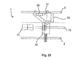
図23は、走査信号を取得する変形例を示すが、効果は少し劣る。この変形例によれば、従来のとおりセンサ74は走査部内に回転ポリゴンミラー11に面して配置され、偏向ミラーは設けられていない。この場合、光受信装置31/光検出素子30のモジュールはセンサ74とは別の空間において(図23の上部)維持されなければならないため、コードリーダ1の体積は大きくなる。
FIG. 23 shows a modification in which the scanning signal is acquired, but the effect is slightly inferior. According to this modification, the
以上、光受信装置31、51および対応する受信部を図1から3の小型光学式コードリーダに関連して説明したが、これらがその他のタイプおよび形状の光学式コードリーダに効果的に使用されることは理解されるべきである。
The
これに対して、上述のコードリーダの好ましい実施形態は、それ自体が革新的なその他の構成を有することも理解されるべきである。このような構成には、2つのPCBのうちの一方を曲げることのできる構成、および弾性リングを介する位置合わせ調整によって固定される能力、ならびに受信部と走査部の間の空間的中間位置における走査信号検出素子(ミラーおよびセンサ)の配置が含まれる。 In contrast, it should also be understood that the preferred embodiment of the code reader described above has other configurations that are innovative in themselves. Such a configuration includes a configuration in which one of the two PCBs can be bent and the ability to be fixed by alignment adjustment via an elastic ring, and scanning at a spatially intermediate position between the receiver and the scanner. An arrangement of signal detection elements (mirrors and sensors) is included.
本発明のコードリーダ1によれば、リニアコード、詳細にはバーコードおよびスタック型コード(例えば、PDF417)のみでなく、文字を含む二次元コードを読み取ることも可能である点は理解されるべきである。ただし、二次元コードを読み取る場合には、走査線に対して垂直方向の第2の走査機構が設けられて走査線のラスタを構成する必要がある。しかし、いずれにしても、ラスタパターンの拡張は光受信装置31の視野内に入ることから、二次元コードの読み取りも可能である。第2の走査機構としては、例えば、ポリゴンミラー11の複数の面の傾斜を異ならせるもの、第2の振動鏡、または例えばコンベアベルト上で運ばれる物体の光学コードの場合におけるコードリーダ1と光学コードとの相対移動などがある。
It should be understood that according to the
1 光学式コードリーダ
30 光検出素子
31(51) 光受信装置
32(52) 光入射面
33(53) 光主射面
34(54) 傾斜面
DESCRIPTION OF
Claims (32)
光検出素子(30)と結合する光出射面(33,53)であって、前記入射面(32,52)に対して垂直である光出射面(33,53)と、
前記入射面(32,52)および前記出射面(33,53)に対して傾斜している傾斜面(34,54)とを有する、透明材料の中実体を備えた、光学式コードリーダ(1)の光受信装置(31,51)であって、
走査線方向の受光角(θ||)、およびこの受光角(θ||)よりも小さい、走査線に対して垂直方向の受光角(θ⊥)の範囲内で前記入射面(32,52)から入る光が、全内反射によって前記出射面(33,53)に集光されるように、光受信装置(31,51)の前記各面(32〜38,40〜42,40’,41’,42’;52〜54,56〜60,60’)が相互に配置されている、光受信装置(31,51)。A light incident surface (32, 52);
A light exit surface (33, 53) coupled to the light detection element (30), the light exit surface (33, 53) being perpendicular to the entrance surface (32, 52);
An optical code reader (1) having a solid body of a transparent material having an inclined surface (34, 54) inclined with respect to the incident surface (32, 52) and the emitting surface (33, 53). ) Optical receiver (31, 51),
The incident surface (32, 52 ) within a range of a light receiving angle (θ || ) in the scanning line direction and a light receiving angle (θ | ) perpendicular to the scanning line, which is smaller than the light receiving angle (θ || ). ) So that the light entering from the light receiving device (31, 51) is condensed by the total internal reflection on the light emitting surface (33, 53), the surfaces (32-38, 40-42, 40 ′, 41 ', 42'; 52-54, 56-60, 60 ') are mutually arranged, optical receivers (31, 51).
Applications Claiming Priority (2)
| Application Number | Priority Date | Filing Date | Title |
|---|---|---|---|
| EP05425619A EP1760630B1 (en) | 2005-09-05 | 2005-09-05 | Light concentrator for an optical code reader |
| PCT/EP2006/008609 WO2007028562A2 (en) | 2005-09-05 | 2006-09-04 | Light concentrator for an optical code reader |
Publications (2)
| Publication Number | Publication Date |
|---|---|
| JP2009507283A JP2009507283A (en) | 2009-02-19 |
| JP4339926B2 true JP4339926B2 (en) | 2009-10-07 |
Family
ID=35559406
Family Applications (1)
| Application Number | Title | Priority Date | Filing Date |
|---|---|---|---|
| JP2008528434A Active JP4339926B2 (en) | 2005-09-05 | 2006-09-04 | Optical receiver for optical code reader |
Country Status (6)
| Country | Link |
|---|---|
| US (1) | US7956340B2 (en) |
| EP (1) | EP1760630B1 (en) |
| JP (1) | JP4339926B2 (en) |
| AT (1) | ATE490514T1 (en) |
| DE (1) | DE602005025120D1 (en) |
| WO (1) | WO2007028562A2 (en) |
Families Citing this family (11)
| Publication number | Priority date | Publication date | Assignee | Title |
|---|---|---|---|---|
| EP2181345B1 (en) * | 2007-08-22 | 2017-04-19 | Koninklijke Philips N.V. | Reflector and light collimator arrangement for improved light collection in scintillation detectors |
| DE102008014349B4 (en) * | 2008-03-14 | 2010-06-10 | Leuze Electronic Gmbh & Co Kg | Optical sensor |
| US8195884B2 (en) * | 2008-09-18 | 2012-06-05 | International Business Machines Corporation | Network on chip with caching restrictions for pages of computer memory |
| EP2577372A1 (en) * | 2010-06-01 | 2013-04-10 | Apple Inc. | Hybrid optical connector |
| USD743397S1 (en) * | 2014-06-20 | 2015-11-17 | Datalogic Ip Tech S.R.L. | Optical scanner |
| CA2981078C (en) | 2015-03-27 | 2023-08-22 | Penguin Automated Systems Inc. | Omnidirectional optical wireless communications receiver & system |
| USD802593S1 (en) * | 2015-08-28 | 2017-11-14 | Hand Held Products, Inc. | Scanner |
| USD852194S1 (en) * | 2016-03-25 | 2019-06-25 | Datalogic Ip Tech S.R.L. | Code reader |
| USD891431S1 (en) * | 2018-03-02 | 2020-07-28 | Datalogic Ip Tech S.R.L. | Optical scanner |
| US11223814B2 (en) * | 2019-05-28 | 2022-01-11 | Lumileds Llc | Imaging optics for one-dimensional array detector |
| US12141651B2 (en) * | 2019-06-03 | 2024-11-12 | Zebra Technologies Corporation | Digital barcode reader |
Family Cites Families (8)
| Publication number | Priority date | Publication date | Assignee | Title |
|---|---|---|---|---|
| US5357101A (en) * | 1992-09-15 | 1994-10-18 | Gap Technologies, Incorporated | Electro-optical transceiver with nonimaging concentrator |
| US5671004A (en) * | 1994-04-14 | 1997-09-23 | Dainippon Screen Manufacturing Co., Ltd. | Internal drum scanning type image recording apparatus |
| US5530940A (en) * | 1995-02-02 | 1996-06-25 | Rohm And Haas Company | Coupling device for light pipe system |
| JP2002007981A (en) | 2000-06-20 | 2002-01-11 | Sony Corp | Information recording medium and information reproducing apparatus using the same |
| GB0021709D0 (en) * | 2000-09-05 | 2000-10-18 | Univ Warwick | Wireless communication receivers |
| US20020050519A1 (en) * | 2000-10-26 | 2002-05-02 | Oliva Guido M. | Laser module for reading optical codes |
| EP2093694B1 (en) | 2000-10-26 | 2011-06-22 | Datalogic S.p.A. | Receiving chamber for a laser reader |
| JP2004127220A (en) | 2002-10-01 | 2004-04-22 | Aisin Engineering Kk | Code reader |
-
2005
- 2005-09-05 DE DE602005025120T patent/DE602005025120D1/en not_active Expired - Lifetime
- 2005-09-05 EP EP05425619A patent/EP1760630B1/en not_active Expired - Lifetime
- 2005-09-05 AT AT05425619T patent/ATE490514T1/en not_active IP Right Cessation
-
2006
- 2006-09-04 US US12/065,710 patent/US7956340B2/en active Active
- 2006-09-04 JP JP2008528434A patent/JP4339926B2/en active Active
- 2006-09-04 WO PCT/EP2006/008609 patent/WO2007028562A2/en not_active Ceased
Also Published As
| Publication number | Publication date |
|---|---|
| EP1760630A1 (en) | 2007-03-07 |
| WO2007028562A2 (en) | 2007-03-15 |
| ATE490514T1 (en) | 2010-12-15 |
| US7956340B2 (en) | 2011-06-07 |
| DE602005025120D1 (en) | 2011-01-13 |
| US20080245982A1 (en) | 2008-10-09 |
| WO2007028562A3 (en) | 2007-05-31 |
| JP2009507283A (en) | 2009-02-19 |
| EP1760630B1 (en) | 2010-12-01 |
Similar Documents
| Publication | Publication Date | Title |
|---|---|---|
| JP3441580B2 (en) | Reader | |
| US5786585A (en) | Optical symbol (bar code) reading systems and devices | |
| AU684569B2 (en) | Optical symbol (bar code) reading systems and devices | |
| JP4339926B2 (en) | Optical receiver for optical code reader | |
| JPS62147576A (en) | Pattern reader | |
| KR100374244B1 (en) | Optical Device | |
| TW200306711A (en) | Optical part for two-way optical communication | |
| EP0553504A1 (en) | Optical scanning system comprising optical chopper | |
| US6273337B1 (en) | Tilted offset barcode scanner | |
| US6715683B2 (en) | Optical data code reader | |
| WO2006016504A1 (en) | Optical device for photoelectric sensor and photoelectric sensor using the same | |
| JPH04211881A (en) | Stationary barcode reader | |
| US8056806B2 (en) | Machine-readable symbol reader and method employing an ultracompact light concentrator with adaptive field of view | |
| JP2725511B2 (en) | Symbol reader | |
| JP2751644B2 (en) | Optical scanning device | |
| KR100573583B1 (en) | Chip Mounter Alignment Unit | |
| JP3564062B2 (en) | Optical scanning device | |
| KR930001470B1 (en) | Portable Bar Code Laser Scanning Head | |
| JPS6372020A (en) | Photoelectric switch | |
| JP2003207732A (en) | Laser module and optical scanner equipped with the same | |
| JPH0373082A (en) | Laser reader | |
| JPH02161578A (en) | barcode scanner | |
| JP2005018034A (en) | Optical scanning device, code reading device, and bar code reading device | |
| JPH02101594A (en) | Bar-code scanner |
Legal Events
| Date | Code | Title | Description |
|---|---|---|---|
| A601 | Written request for extension of time |
Free format text: JAPANESE INTERMEDIATE CODE: A601 Effective date: 20081112 |
|
| A602 | Written permission of extension of time |
Free format text: JAPANESE INTERMEDIATE CODE: A602 Effective date: 20081119 |
|
| A521 | Request for written amendment filed |
Free format text: JAPANESE INTERMEDIATE CODE: A523 Effective date: 20090226 |
|
| TRDD | Decision of grant or rejection written | ||
| A01 | Written decision to grant a patent or to grant a registration (utility model) |
Free format text: JAPANESE INTERMEDIATE CODE: A01 Effective date: 20090602 |
|
| A01 | Written decision to grant a patent or to grant a registration (utility model) |
Free format text: JAPANESE INTERMEDIATE CODE: A01 |
|
| A61 | First payment of annual fees (during grant procedure) |
Free format text: JAPANESE INTERMEDIATE CODE: A61 Effective date: 20090702 |
|
| R150 | Certificate of patent or registration of utility model |
Free format text: JAPANESE INTERMEDIATE CODE: R150 Ref document number: 4339926 Country of ref document: JP Free format text: JAPANESE INTERMEDIATE CODE: R150 |
|
| FPAY | Renewal fee payment (event date is renewal date of database) |
Free format text: PAYMENT UNTIL: 20120710 Year of fee payment: 3 |
|
| FPAY | Renewal fee payment (event date is renewal date of database) |
Free format text: PAYMENT UNTIL: 20130710 Year of fee payment: 4 |
|
| R250 | Receipt of annual fees |
Free format text: JAPANESE INTERMEDIATE CODE: R250 |
|
| R250 | Receipt of annual fees |
Free format text: JAPANESE INTERMEDIATE CODE: R250 |
|
| R250 | Receipt of annual fees |
Free format text: JAPANESE INTERMEDIATE CODE: R250 |
|
| R250 | Receipt of annual fees |
Free format text: JAPANESE INTERMEDIATE CODE: R250 |
|
| R250 | Receipt of annual fees |
Free format text: JAPANESE INTERMEDIATE CODE: R250 |
|
| R250 | Receipt of annual fees |
Free format text: JAPANESE INTERMEDIATE CODE: R250 |
|
| R250 | Receipt of annual fees |
Free format text: JAPANESE INTERMEDIATE CODE: R250 |
|
| R250 | Receipt of annual fees |
Free format text: JAPANESE INTERMEDIATE CODE: R250 |
|
| R250 | Receipt of annual fees |
Free format text: JAPANESE INTERMEDIATE CODE: R250 |
|
| R250 | Receipt of annual fees |
Free format text: JAPANESE INTERMEDIATE CODE: R250 |
|
| R250 | Receipt of annual fees |
Free format text: JAPANESE INTERMEDIATE CODE: R250 |
|
| R250 | Receipt of annual fees |
Free format text: JAPANESE INTERMEDIATE CODE: R250 |
|
| R250 | Receipt of annual fees |
Free format text: JAPANESE INTERMEDIATE CODE: R250 |
|
| R250 | Receipt of annual fees |
Free format text: JAPANESE INTERMEDIATE CODE: R250 |