JP4323288B2 - Insertion support system - Google Patents
Insertion support system Download PDFInfo
- Publication number
- JP4323288B2 JP4323288B2 JP2003373810A JP2003373810A JP4323288B2 JP 4323288 B2 JP4323288 B2 JP 4323288B2 JP 2003373810 A JP2003373810 A JP 2003373810A JP 2003373810 A JP2003373810 A JP 2003373810A JP 4323288 B2 JP4323288 B2 JP 4323288B2
- Authority
- JP
- Japan
- Prior art keywords
- image
- area
- route
- biopsy
- displayed
- Prior art date
- Legal status (The legal status is an assumption and is not a legal conclusion. Google has not performed a legal analysis and makes no representation as to the accuracy of the status listed.)
- Expired - Lifetime
Links
Images


Classifications
-
- A—HUMAN NECESSITIES
- A61—MEDICAL OR VETERINARY SCIENCE; HYGIENE
- A61B—DIAGNOSIS; SURGERY; IDENTIFICATION
- A61B1/00—Instruments for performing medical examinations of the interior of cavities or tubes of the body by visual or photographical inspection, e.g. endoscopes; Illuminating arrangements therefor
- A61B1/00002—Operational features of endoscopes
- A61B1/00043—Operational features of endoscopes provided with output arrangements
- A61B1/00045—Display arrangement
- A61B1/0005—Display arrangement combining images e.g. side-by-side, superimposed or tiled
-
- A—HUMAN NECESSITIES
- A61—MEDICAL OR VETERINARY SCIENCE; HYGIENE
- A61B—DIAGNOSIS; SURGERY; IDENTIFICATION
- A61B1/00—Instruments for performing medical examinations of the interior of cavities or tubes of the body by visual or photographical inspection, e.g. endoscopes; Illuminating arrangements therefor
- A61B1/00002—Operational features of endoscopes
- A61B1/00004—Operational features of endoscopes characterised by electronic signal processing
- A61B1/00009—Operational features of endoscopes characterised by electronic signal processing of image signals during a use of endoscope
-
- G—PHYSICS
- G06—COMPUTING OR CALCULATING; COUNTING
- G06T—IMAGE DATA PROCESSING OR GENERATION, IN GENERAL
- G06T7/00—Image analysis
- G06T7/0002—Inspection of images, e.g. flaw detection
- G06T7/0012—Biomedical image inspection
Landscapes
- Health & Medical Sciences (AREA)
- Life Sciences & Earth Sciences (AREA)
- Engineering & Computer Science (AREA)
- Surgery (AREA)
- General Health & Medical Sciences (AREA)
- Nuclear Medicine, Radiotherapy & Molecular Imaging (AREA)
- Physics & Mathematics (AREA)
- Medical Informatics (AREA)
- Radiology & Medical Imaging (AREA)
- Animal Behavior & Ethology (AREA)
- Biomedical Technology (AREA)
- Heart & Thoracic Surgery (AREA)
- Pathology (AREA)
- Molecular Biology (AREA)
- Optics & Photonics (AREA)
- Biophysics (AREA)
- Public Health (AREA)
- Veterinary Medicine (AREA)
- Signal Processing (AREA)
- Quality & Reliability (AREA)
- Computer Vision & Pattern Recognition (AREA)
- General Physics & Mathematics (AREA)
- Theoretical Computer Science (AREA)
- Apparatus For Radiation Diagnosis (AREA)
- Endoscopes (AREA)
- Processing Or Creating Images (AREA)
- Image Processing (AREA)
- Image Analysis (AREA)
- Instruments For Viewing The Inside Of Hollow Bodies (AREA)
Description
本発明は、内視鏡の挿入を支援する挿入支援システムに関する。 The present invention relates to an insertion support system that supports insertion of an endoscope.
近年、画像による診断が広く行われるようになっており、例えばX線CT(Computed Tomography)装置等により被検体の断層像を撮像することにより被検体内に3次元画像データを得て、該3次元画像データを用いて目的の診断が行われるようになってきた。 In recent years, diagnosis based on images has been widely performed. For example, by taking a tomographic image of a subject with an X-ray CT (Computed Tomography) apparatus or the like, three-dimensional image data is obtained in the subject, and the 3D image data is obtained. The target diagnosis has come to be performed using the dimensional image data.
CT装置では、X線照射・検出を連続的に回転させつつ被検体を体軸方向に連続送りすることにより、被検体の3次元領域について螺旋状の連続スキャン(ヘリカルスキャン:helical scan)を行い、3次元領域の連続するスライスの断層像から、3次元画像を作成することが行われる。 In the CT apparatus, by continuously feeding the subject in the body axis direction while continuously rotating the X-ray irradiation / detection, a helical continuous scan (helical scan) is performed on the three-dimensional region of the subject. A three-dimensional image is created from tomographic images of successive slices of a three-dimensional region.
そのような3次元画像の1つに、肺の気管支の3次元像がある。気管支の3次元像は、例えば肺癌等が疑われる異常部の位置を3次元的に把握するのに利用される。そして、異常部を生検によって確認するために、気管支内視鏡を挿入して先端部から生検針や生検鉗子等を出して組織のサンプル(sample)を採取することが行われる。 One such 3D image is a 3D image of the lung bronchi. The three-dimensional image of the bronchus is used to three-dimensionally grasp the position of an abnormal part suspected of lung cancer, for example. In order to confirm the abnormal portion by biopsy, a bronchoscope is inserted and a biopsy needle, biopsy forceps, or the like is taken out from the distal end portion and a tissue sample is taken.
気管支のように、多段階の分岐を有する体内の管路では、異常部の所在が分岐の末梢に近いとき、内視鏡の先端を短時間で正しく目的部位に到達させることが難しいために、例えば特開2000−135215号公報等では、被検体の3次元領域の画像データに基づいて前記被検体内の管路の3次元像を作成し、前記3次元像上で前記管路に沿って目的点までの経路を求め、前記経路に沿った前記管路の仮想的な内視鏡画像を前記画像データに基づいて作成し、前記仮想的な内視鏡画像を表示することで、気管支内視鏡を目的部位にナビゲーションする装置が提案されている。
しかしながら、内視鏡の体腔内への挿入の際には、目的組織の生検処置を目的とすることがあり、その場合、この生検処置を行う目的組織は1カ所に限らず、1度の挿入で複数箇所の目的組織の生検処置がなされることがあるが、従来の仮想的な内視像によるナビゲーションでは、生検処置を行う目的組織を視認することが出来ないといった問題がある。 However, when the endoscope is inserted into the body cavity, there is a case where the target tissue is biopsyed. In this case, the target tissue for performing the biopsy treatment is not limited to one place, but once. In some cases, the biopsy procedure of the target tissue at a plurality of locations may be performed by insertion of the target, but the conventional navigation using the virtual endoscopic image has a problem that the target tissue on which the biopsy procedure is performed cannot be visually recognized. .
本発明は、上記事情に鑑みてなされたものであり、生検対象の目的組織の情報を仮想的な内視像上で提供することのできる挿入支援システムを提供することを目的としている。 The present invention has been made in view of the above circumstances, and an object thereof is to provide an insertion support system capable of providing information on a target tissue to be biopsyed on a virtual endoscopic image.
本発明の挿入支援システムは、被検体の3次元領域の画像データに基づき前記被検体内の体腔路の仮想画像を生成する仮想画像生成手段と、内視鏡の前記被検体内の前記体腔路への挿入ルートの始点を設定するルート始点設定手段と、前記挿入ルートの終点を設定するルート終点設定手段と、前記終点近傍の前記被検体内の目的エリアを前記画像データの中から抽出するエリア抽出手段と、前記エリア抽出手段が抽出した前記目的エリアのエリア画像を、前記目的エリアのボクセルデータと、表示装置上に表示されている前記仮想画像の前記3次元領域上の現在位置及び前記目的エリアの位置から算出された距離とに基づいて、前記表示装置上に表示される形状及び大きさを調整して生成するエリア画像生成手段と、前記エリア画像を前記仮想画像に重畳する画像重畳手段とを備えて構成される。
Insertion support system of the present invention, a virtual image generating means for generating a virtual image of the body cavity path in the subject based on the image data of a three-dimensional area of the subject, the cavity path within the subject of the endoscope Route start point setting means for setting the start point of the insertion route to the route, route end point setting means for setting the end point of the insertion route, and an area for extracting the target area in the subject near the end point from the image data An extraction unit, an area image of the target area extracted by the area extraction unit , voxel data of the target area, a current position on the three-dimensional region of the virtual image displayed on a display device, and the target based on the distance calculated from the position of the area, and the area image generating means for generating and adjusting the shape and size are displayed on the display device, the area image the temporary Constructed and an image superimposing means for superimposing the image.
本発明の挿入支援システムは、生検対象の目的組織の情報を仮想的な内視像上で提供することができるという効果がある。 The insertion support system of the present invention has an effect that information on a target tissue to be biopsied can be provided on a virtual endoscopic image.
以下、図面を参照しながら本発明の実施例について述べる。 Embodiments of the present invention will be described below with reference to the drawings.
図1ないし図23は本発明の実施例1に係わり、図1は気管支挿入支援システムの構成を示す構成図、図2は図1の挿入支援装置によるナビゲーションデータの生成処理の流れを示すフローチャート、図3は図2の処理で展開されるルート設定画面を示す第1の図、図4は図2の処理で展開されるルート設定画面を示す第2の図、図5は図2のルート設定処理の流れを示すフローチャート、図6は図5の処理で展開されるルート設定画面を示す第1の図、図7は図5の処理で展開されるルート設定画面を示す第2の図、図8は図5の処理で展開されるルート設定画面を示す第3の図、図9は図1の気管支挿入支援システムによるナビゲーション処理で展開される挿入支援画面を示す図、図10は図9の挿入支援画面での生検対象部画像の重畳処理の流れを示すフローチャート、図11は図10の処理で展開される挿入支援画面を示す第1の図、図12は図10の処理で展開される挿入支援画面を示す第2の図図10の処理で展開される挿入支援画面の第1の変形例を示す図、図14は図10の処理で展開される挿入支援画面の第2の変形例を示す第1の図、図15は図10の処理で展開される挿入支援画面の第2の変形例を示す第2の図、図16は図10の処理で展開される挿入支援画面の第3の変形例を示す第1の図、図17は図10の処理で展開される挿入支援画面の第3の変形例を示す第2の図、図18は図10の処理で展開される挿入支援画面の第4の変形例を示す図、図19は図10の処理で展開される挿入支援画面の第5の変形例を示す図、図20は図10の処理で展開される挿入支援画面の第6の変形例を説明する第1の図、図21は図10の処理で展開される挿入支援画面の第6の変形例を説明する第2の図、図22は図10の処理で展開される挿入支援画面の第7の変形例を示す第1の図、図23は図10の処理で展開される挿入支援画面の第7の変形例を示す第2の図である。
FIGS. 1 to 23 relate to
図1に示すように、本実施の形態の気管支挿入支援システム1は、気管支内視鏡装置3と、挿入支援装置5とから構成される。
As shown in FIG. 1, the bronchial
挿入支援装置5はCT画像データに基づき気管支内部の仮想の内視像(以下、VBS画像と記す)を生成すると共に気管支内視鏡装置3により得られる内視鏡画像(以下、ライブ画像と記す)とVBS画像を合成してモニタ6に表示し気管支内視鏡装置3の気管支へ挿入支援を行う。
The
また、気管支内視鏡装置3は、図示はしないが、撮像手段を有する気管支鏡と、気管支鏡に照明光を供給する光源と、気管支鏡からの撮像信号を信号処理するカメラコントロールユニット等から構成され、気管支鏡を患者体内の気管支に挿入し気管支内を撮像し気管支末端の目的組織を生検すると共に、ライブ画像とVBS画像を合成してモニタ7に表示する。
Although not shown, the
モニタ7はタッチパネルからなる入力部8が設けられ、挿入手技を行いながら容易にタッチパネルからなる入力部8を操作することが可能となっている。
The
挿入支援装置5は、患者のX線断層像を撮像する図示しない公知のCT装置で生成されたCT画像データを、例えばMO(Magnetic Optical)ディスク装置やDVD(Digital Versatile Disk)装置等、可搬型の記憶媒体を介して取り込むCT画像データ取り込み部11と、CT画像データ取り込み部11によって取り込まれたCT画像データを格納するCT画像データ格納部12と、CT画像データ格納部12に格納されているCT画像データに基づきMPR画像(多断面再構築画像)を生成するMPR画像生成部13と、MPR画像生成部が生成したMPR画像を有する後述するルート設定画面を生成し気管支内視鏡装置3の気管支への支援ルート(以下、単にルートと記す)を設定するルート設定部14と、CT画像データ格納部12に格納されているCT画像データに基づきルート設定部14によって設定されたルートの連続したVBS画像をフレーム単位で生成する仮想画像生成手段としてのVBS画像生成部15と、VBS画像生成部15が生成したVBS画像を格納するVBS画像格納部16と、気管支内視鏡装置3からの撮像信号及び入力部8からの入力信号を入力し、ライブ画像、VBS画像及び複数のサムネイルVBS画像からなる後述する挿入支援画面を生成するナビゲーション画像生成手段としての画像処理部17と、ルート設定部14が生成したルート設定画面及び画像処理部17が生成した挿入支援画面をモニタ6に表示させる画像表示制御部18と、ルート設定部14に対して設定情報を入力するキーボード及びポインティングデバイスからなる入力装置19と、画像処理部17がデータ処理に使用するメモリ20とから構成される。
The
気管支内視鏡装置3は、挿入支援装置5の画像処理部17からVBS画像及びサムネイルVBS画像を受け取りライブ画像と合成してモニタ7に表示すると共に、モニタ7のタッチパネルからなる入力部8からの入力情報を挿入支援装置5の画像処理部17に出力するようになっている。
The bronchial
なお、CT画像データ格納部12及びVBS画像格納部16は、1つのハードディスクによって構成してもよく、また、MPR画像生成部13、ルート設定部14、VBS画像生成部15及び画像処理部17は1つの演算処理回路で構成することができる。また、CT画像データ取り込み部11はMOあるいはDVD等の可搬型の記憶媒体を介してCT画像データを取り込みとしたが、CT装置あるいはCT画像データを保存している院内サーバが院内LANに接続されている場合には、CT画像データ取り込み部11を該院内LANに接続可能なインターフェイス回路により構成し、院内LANを介してCT画像データを取り込むようにしてもよい。
The CT image
このように構成された本実施の形態の作用について説明する。 The operation of the present embodiment configured as described above will be described.
図2に示すように、気管支内視鏡装置3による観察・処置に先立ち、挿入支援装置5は、ステップS1でCT画像データ取り込み部11によりCT装置で生成された患者のCT画像データを取り込み、ステップS2で取り込んだCT画像データをCT画像データ格納部12に格納する。
As shown in FIG. 2, prior to the observation / treatment by the
ステップS3でルート設定部14により、図3に示すようなルート設定画面21をモニタ6に表示させ、ルート設定画面21上の患者情報タグ画面22で患者情報を選択する。この選択により、ステップS4で選択された患者の例えば3つの異なる多断面像からなるMPR画像が生成され、ステップS5でこのMPR画像23が図4に示すようなルート設定画面21に表示される。
In step S <b> 3, the
なお、患者情報タグ画面22での患者情報の選択は、入力装置19により患者を識別する患者IDを入力することで行われる。
The selection of patient information on the patient
次に、ステップS6でルート設定画面21上のルート設定タグ24(図3参照)を入力装置19により選択すると、図4に示すようなルート設定タグ画面25がルート設定画面21に表示され、後述するルート設定処理を行い、気管支での気管支鏡の挿入支援のルートを設定する。
Next, when the route setting tag 24 (see FIG. 3) on the
挿入支援のルートが設定されると、ステップS7でVBS画像生成部15により設定した全ルートの連続したVBS画像をフレーム単位で生成し、ステップS8で生成したVBS画像をVBS画像格納部16に格納する。
When the insertion support route is set, continuous VBS images of all routes set by the VBS
上記のステップS1〜S8の処理により、気管支鏡による観察・処置時の挿入支援装置5による挿入支援の準備が完了する。
With the processing of steps S1 to S8 described above, preparation for insertion support by the
ここで、上記ステップS6のルート設定処理を図5を用いて説明する。 Here, the route setting process in step S6 will be described with reference to FIG.
図5に示すように、ステップS6のルート設定処理では、入力装置19を操作することで、図4に示したルート設定タグ画面25上のルート探索ボタンをクリックすると、ステップS11で図6に示すようなルートの始点の入力を促す始点入力指示ウインドウ31がルート設定画面21上に表示され、ルート設定画面21上にカーソル30を用いてMPR画像23のうちの1つの断層像上で始点を設定する。始点を設定すると他のMPR画像23の2つの断層像上にも対応する位置に始点が設定されると共に、図7に示すようなルートの終点の入力を促す終点入力指示ウインドウ32がルート設定画面21上に表示される。
As shown in FIG. 5, in the route setting process in step S6, when the route search button on the route
そこで、ステップS12で始点の設定と同様に、ルート設定画面21上にカーソル30を用いてMPR画像23のうちの1つの断層像上で終点を設定する。終点を設定すると他のMPR画像23の2つの断層像上にも対応する位置に終点が設定される。この終点の設定は、術者がMPR画像23上で目的組織を見出し、目的組織の生検処置等を行う位置の設定であって、終点の設定が設定されると、CT画像データに対する画像処理等により目的組織(終点)を含む生検対象部エリアをボクセル単位で抽出し、該ボクセルデータが生検対象部エリアの位置データと共にVBS画像格納部16に保存される。
Therefore, in step S12, the end point is set on one tomographic image of the
始点と終点が設定されると、ステップS13でルート設定部14は始点から終点に至る気管支内のルートを探索する。気管支は複雑な経路を有しているので、始点から終点に至る気管支内のルートが一意的に決まるとは限らないので、ルート設定部14ではステップS13では、始点から終点に至る気管支内のルートの第1候補を探索する。
When the start point and end point are set, the
そして、ルート設定部14はルート設定画面21上において、図8に示すように、ステップS14で探索されたルートをMPR画像23に重畳して表示すると共に、ルートの確定等の入力を促すルート確定ウインドウ33を表示する。
Then, on the
ルート確定ウインドウ33には、探索したルートの確定を指示するルート確定ボタン41と、次候補のルートの探索を指示する次候補探索ボタン42と、始点及び終点を再設定し直すルート再設定ボタン43と、ルート探索処理をキャンセルするキャンセルボタン44とを備えている。
The
ステップS15で次候補探索ボタン42がクリックされたかどうか判断し、クリックされたならばステップS16で次候補のルートを自動探索してステップS17に進み、クリックされない場合にはステップS18に進む。ステップS17では次候補を探索した結果、次候補が存在するかどうかを判断し、存在しない場合には図示はしないが次候補ルートが存在しない旨の警告を表示しステップS11に戻り、存在する場合にはステップS14に戻る。
In step S15, it is determined whether or not the next
ステップS18では、ルート確定ボタン41がクリックされたかどうか判断し、クリックされたならばステップS19に進み、クリックされない場合にはステップS20に進む。
In step S18, it is determined whether or not the
ステップS20でルートが決定された後、ステップS21でルート再設定ボタン43がクリックされたかどうか判断し、クリックされない場合にはステップS11に戻り、クリックされたならば処理を終了して図2のステップS7に戻る。また、ステップS19では、次候補探索ボタン42がクリックされたかどうか判断し、クリックされたならばステップS11に戻り、クリックされない場合にはステップS15に戻る。
After the route is determined in step S20, it is determined whether or not the
上記ステップS6の処理は複数の終点に対してルート設定ができ、設定されたルートが登録される。 In the process of step S6, a route can be set for a plurality of end points, and the set route is registered.
このようにしてルート設定がなされた挿入支援装置5及び気管支内視鏡装置3による観察・処置時の挿入支援について説明する。なお、以下では、ルートの分岐点が10カ所の場合を例に説明する。
The insertion support at the time of observation and treatment by the
挿入支援装置5による挿入支援下での気管支内視鏡検査を開始すると、モニタ6に図9に示すような挿入支援画面51を表示する。
When the bronchoscopy under the insertion support by the
この挿入支援画面51は、気管支の3次元画像52aを表示する3次元画像表示エリア52と、VBS画像像53aを表示するVBS画像表示エリア53と、ルートの全ての分岐点でのVBS画像像53aを縮小して分岐サムネイルVBS画像54(a)〜54(j)として表示する分岐サムネイルVBS画像エリア54とからなる。
The
ここで、VBS画像表示エリア53に表示されるVBS画像53aと同じ分岐サムネイルVBS画像の枠が太枠あるいはカラー表示され、他の分岐サムネイルVBS画像と識別可能となっており、術者はVBS画像表示エリア53に表示されるVBS画像がどの分岐の画像かを容易に認識できるようになっている。
Here, the same branch thumbnail VBS image frame as the
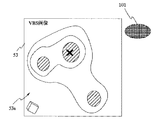
VBS画像表示エリア53のVBS画像53aには、VBS画像格納部16に保存されている終点を含む生検対象部エリアのボクセルデータに基づく複数の生検対象部画像が重畳表示される。生検対象部画像の重畳は、終点の数分だけ行われる。図9では3つの生検対象部画像101a,101b,101cが重畳された際のVBS画像53aを示している。
On the
また、3次元画像表示エリア52の気管支の3次元画像52aにも、生検対象部画像101a,101b,101cに対応した生検対象部エリアの位置を示すマーカ102a,102b,102cが始点103と共に表示され、さらに支援ルート104が表示される。
Also, in the three-
このとき支援ルート104によりアクセス可能な生検対象部エリアの生検対象部画像101a,101bと、支援ルート104から外れた生検対象部画像101cは、異なる表示モード、例えば色分けされて表示される(例えば生検対象部画像101a,101bは青色表示、生検対象部画像101cは赤色表示)。マーカ102a,102b,102cも同様である。なお、色ではなくハッチング等により識別可能に表示してもよい。
At this time, the biopsy
生検対象部画像101a,101b,101cの重畳処理は、具体的には、図10に示すように、ステップS41において、終点を含む生検対象部エリアの位置データ及びボクセルデータをVBS画像格納部16より検索する。そして、ステップS42においてVBS画像表示エリア53に表示されるVBS画像53aの現在位置と生検対象部エリアの位置データとが比較され、VBS画像53aの現在位置と生検対象部エリアの位置との距離を算出する。
Specifically, in the superimposing process of the biopsy
次に、ステップS43において、ボクセルデータ及び算出した距離に基づき、重畳する生検対象部画像の形状及び大きさを調整して、生検対象部画像を生成する。そして、ステップS44においてVBS画像53a上での生検対象部画像重畳位置を算出し、ステップS45でVBS画像53a上に生検対象部画像を重畳表示させ、ステップS46において全ての生検対象部エリアの生検対象部画像をVBS画像53a上に重畳させたかどうか判断し、全ての生検対象部エリアの生検対象部画像の重畳が終了するまで処理を繰り返す。
Next, in step S43, based on the voxel data and the calculated distance, the shape and size of the biopsy target part image to be superimposed are adjusted to generate a biopsy target part image. In step S44, the biopsy target part image superposition position on the
本実施例では、挿入支援が順調になされ、例えば生検対象部画像101aに対応した生検対象部エリアでの生検処置が終了し、生検対象部画像101bに対応した生検対象部エリアでの生検処置を行う場合は、図11に示すように、生検処置が終了した生検対象部エリアの生検対象部画像101aが生検処置が未終了の生検対象部エリアの生検対象部画像101bと異なる色で表示される。すなわち、例えば生検処置が終了した生検対象部エリアの生検対象部画像101aは黄色表示、生検処置が未終了の生検対象部エリアの生検対象部画像101bは青色表示、支援ルート104から外れた生検対象部画像101cは赤色表示といったように表示され、次に生検処置を行う生検対象部エリアをVBS画像53a上で認識可能としている。
In the present embodiment, the insertion support is smoothly performed, for example, the biopsy treatment in the biopsy target part area corresponding to the biopsy
このように本実施例では、VBS画像53a上に生検対象部画像を形状及び大きさを調整して表示するので、生検対象の生検対象部の情報を容易に得ることが可能となり、生検処置を容易に行うことができる。
Thus, in the present embodiment, since the biopsy target part image is displayed on the
また、支援ルート上の生検対象部と支援ルート外の生検対象部とを異なる表示モード(色分け等)で表示しているので、支援ルート上の生検対象部の生検処置が終了した際、挿入位置を始点側に戻し、未生検処置の生検対象部への支援ルートを設定し直すことで、容易に全生検対象部への生検処置に移行することが可能となる。さらに、支援ルート上の生検対象部が複数あっても生検処置済みの生検対象部、未生検処置の生検対象部を異なる表示モードで表示することが出来るので、現在の支援ルート上の生検対象部の生検処置状態を容易に認識することもできる。 In addition, since the biopsy target part on the support route and the biopsy target part outside the support route are displayed in different display modes (color coding, etc.), the biopsy treatment of the biopsy target part on the support route has ended. At this time, by returning the insertion position to the start point side and resetting the support route to the biopsy target part of the unbiopsy procedure, it becomes possible to easily shift to the biopsy procedure to the whole biopsy target part. . Furthermore, even if there are multiple biopsy target parts on the support route, the biopsy target part that has been biopsied and the biopsy target part that has not been biopsyed can be displayed in different display modes, so the current support route The biopsy treatment state of the upper biopsy target part can also be easily recognized.
なお、図12に示すように、例えば支援ルート上の生検対象部画像101bに対応した生検対象部エリアが未生検処置の場合、生検対象部画像101bに対応した生検対象部エリアまでの距離を文字画像201として生検対象部画像101bの近傍に重畳表示してもよい。
In addition, as shown in FIG. 12, for example, when the biopsy target part area corresponding to the biopsy
また、図13に示すように、例えば支援ルート上の生検対象部画像101bに対応した生検対象部エリアが未生検処置の場合、支援ルート上の生検対象部画像101bに対応した生検対象部エリアへの接近に応じて生検対象部画像101bの表示サイズを拡大して表示したり、図14に示すように、支援ルート上の生検対象部画像101bに対応した生検対象部エリアへの接近に応じた距離情報をバー表示部501に表示するようにしてもよく、この場合生検対象部エリアに接近する距離に比例したバーをバー表示部501に表示する。生検対象部エリアにより近付けば図15に示すようにバー表示部501のバーの長さが短くなる。
Also, as shown in FIG. 13, for example, when the biopsy target area corresponding to the biopsy
さらに、例えば支援ルート上の生検対象部画像101bに対応した生検対象部エリアが未生検処置の場合、図16及び図17に示すように、支援ルート上の生検対象部画像101bに対応した生検対象部エリアへの接近に応じてVBS画像表示エリア53のVBS画像53aの色調を変化させても良い。この場合、VBS画像53aの色調をこの場合生検対象部エリアに接近する距離に比例させて、例えば「赤色」から「紫色」に順次替え、VBS画像53aの色調が「紫色」になった時点で、生検対象部画像101bが生検可能位置とする。このような色調変化により生検対象部エリアへの接近を容易に認識が可能となり、また確実に生検可能位置に到達したことが容易に確認することが可能となる。
Furthermore, for example, when the biopsy target part area corresponding to the biopsy
図18に示すように、このような色調変化を分岐サムネイルVBS画像に適用してもよく、色調変化を分岐サムネイルVBS画像に適用することで、色調変化の変遷を術者は憶える必要無く、VBS画像53aの位置が容易に認識できる。
As shown in FIG. 18, such a color tone change may be applied to the branch thumbnail VBS image, and by applying the color tone change to the branch thumbnail VBS image, the operator does not need to remember the transition of the color tone change. The position of the
また、例えば支援ルート上の生検対象部画像101bに対応した生検対象部エリアが未生検処置の場合、図19に示すように、支援ルート上の生検対象部画像101bの代りに、CT画像データ格納部12に格納されているCT画像データに基づきVBS画像生成部15がボクセルデータによる生検対象部画像101bの立体生検対象部画像550bを生成し、立体生検対象部画像550bを表示するようにしても良い。この立体生検対象部画像550bの表示においても、距離に応じた表示(上述した距離情報の重畳表示、バー表示、色調変化表示)を行うことが可能である。
For example, when the biopsy target part area corresponding to the biopsy
また、図20に示すようにVBS画像表示エリア53上より生検対象部画像101に対応した生検対象部エリアが外れた場合には、図21に示すようにVBS画像表示エリア53上に生検対象部エリアがある位置方向に生検対象部エリアの存在を示唆する生検対象部位置方向示唆画像600を破線等で表示してもよい。
Further, when the biopsy target area corresponding to the biopsy
また、VBS画像表示エリア53上より生検対象部画像101に対応した生検対象部エリアが外れた場合には、図22に示すように3次元画像表示エリア52の代りに、生検対象部エリアの位置方向を破線等で示す位置方向画像701を有するレーダ画象のように模式的に示す模式位置方向示唆画像702を有する模式示唆画像エリア703を挿入支援画面51に表示するようにしてもよい。なお、模式位置方向示唆画像702において、VBS画像表示エリア53上に生検対象部エリアが移動した際には、図23に示すように、破線の位置方向画像701から実線の生検対象部画像101に変更する。
When the biopsy target area corresponding to the biopsy
本発明は、上述した実施例に限定されるものではなく、本発明の要旨を変えない範囲において、種々の変更、改変等が可能である。 The present invention is not limited to the above-described embodiments, and various changes and modifications can be made without departing from the scope of the present invention.
1…気管支挿入支援システム
3…気管支内視鏡装置
5…挿入支援装置
6,7…モニタ
8…入力部
11…CT画像データ取り込み部
12…CT画像データ格納部
13…MPR画像生成部
14…ルート設定部
15…VBS画像生成部
16…VBS画像格納部
17…画像処理部
18…画像表示制御部
19…入力装置
代理人 弁理士 伊藤 進
DESCRIPTION OF
Claims (5)
内視鏡の前記被検体内の前記体腔路への挿入ルートの始点を設定するルート始点設定手段と、
前記挿入ルートの終点を設定するルート終点設定手段と、
前記終点近傍の前記被検体内の目的エリアを前記画像データの中から抽出するエリア抽出手段と、
前記エリア抽出手段が抽出した前記目的エリアのエリア画像を、前記目的エリアのボクセルデータと、表示装置上に表示されている前記仮想画像の前記3次元領域上の現在位置及び前記目的エリアの位置から算出された距離とに基づいて、前記表示装置上に表示される形状及び大きさを調整して生成するエリア画像生成手段と、
前記エリア画像を前記仮想画像に重畳する画像重畳手段と、
を備えたことを特徴とする挿入支援システム。 Virtual image generation means for generating a virtual image of a body cavity in the subject based on image data of a three-dimensional region of the subject;
And route start point setting means for the endoscope to set the starting point of the insertion route to the body cavity passage within the object,
Route end point setting means for setting an end point of the insertion route;
Area extraction means for extracting a target area in the subject near the end point from the image data ;
The area image of the target area extracted by the area extraction means is obtained from the voxel data of the target area, the current position on the three-dimensional area of the virtual image displayed on the display device, and the position of the target area. Area image generating means for adjusting and generating the shape and size displayed on the display device based on the calculated distance ;
Image superimposing means for superimposing the area image on the virtual image ;
An insertion support system characterized by comprising:
複数生成されたエリア画像のうち、生検処置が終了したエリア画像と、前記複数生成されたエリア画像のうち、生検処置が終了していないエリア画像とを異なる表示モードにより前記表示装置上で表示させる表示手段を有することを特徴とする請求項1に記載の挿入支援システム。 Of the plurality of generated area images, an area image for which biopsy treatment has been completed and an area image for which biopsy treatment has not been completed among the plurality of generated area images are displayed on the display device in different display modes. The insertion support system according to claim 1, further comprising display means for displaying.
Priority Applications (1)
| Application Number | Priority Date | Filing Date | Title |
|---|---|---|---|
| JP2003373810A JP4323288B2 (en) | 2003-10-31 | 2003-10-31 | Insertion support system |
Applications Claiming Priority (1)
| Application Number | Priority Date | Filing Date | Title |
|---|---|---|---|
| JP2003373810A JP4323288B2 (en) | 2003-10-31 | 2003-10-31 | Insertion support system |
Publications (2)
| Publication Number | Publication Date |
|---|---|
| JP2005131319A JP2005131319A (en) | 2005-05-26 |
| JP4323288B2 true JP4323288B2 (en) | 2009-09-02 |
Family
ID=34649719
Family Applications (1)
| Application Number | Title | Priority Date | Filing Date |
|---|---|---|---|
| JP2003373810A Expired - Lifetime JP4323288B2 (en) | 2003-10-31 | 2003-10-31 | Insertion support system |
Country Status (1)
| Country | Link |
|---|---|
| JP (1) | JP4323288B2 (en) |
Families Citing this family (16)
| Publication number | Priority date | Publication date | Assignee | Title |
|---|---|---|---|---|
| US7536216B2 (en) * | 2004-10-18 | 2009-05-19 | Siemens Medical Solutions Usa, Inc. | Method and system for virtual endoscopy with guidance for biopsy |
| JP5442993B2 (en) * | 2005-10-11 | 2014-03-19 | コーニンクレッカ フィリップス エヌ ヴェ | 3D instrument path planning, simulation and control system |
| JP5426835B2 (en) * | 2008-03-28 | 2014-02-26 | トーヨーカネツソリューションズ株式会社 | Picking system |
| JP5398220B2 (en) * | 2008-10-17 | 2014-01-29 | 株式会社東芝 | Ultrasonic diagnostic apparatus and computer program therefor |
| JP5612608B2 (en) * | 2009-01-30 | 2014-10-22 | コーニンクレッカ フィリップス エヌ ヴェ | Inspection device |
| JP5748520B2 (en) * | 2011-03-25 | 2015-07-15 | 富士フイルム株式会社 | Endoscope insertion support apparatus, operation method thereof, and endoscope insertion support program |
| JP2013128731A (en) * | 2011-12-22 | 2013-07-04 | Hitachi Medical Corp | Ultrasound treatment apparatus and surgery assistance system |
| GB2505926A (en) * | 2012-09-14 | 2014-03-19 | Sony Corp | Display of Depth Information Within a Scene |
| JP2014104328A (en) * | 2012-11-30 | 2014-06-09 | Toyota Keeramu:Kk | Operation support system, operation support method, and operation support program |
| US20160000414A1 (en) * | 2014-07-02 | 2016-01-07 | Covidien Lp | Methods for marking biopsy location |
| EP3174490B1 (en) | 2014-07-28 | 2020-04-15 | Intuitive Surgical Operations, Inc. | Systems and methods for planning multiple interventional procedures |
| JP6400994B2 (en) * | 2014-09-05 | 2018-10-03 | オリンパス株式会社 | Inspection image display system |
| JP6608111B2 (en) * | 2016-09-28 | 2019-11-20 | 富士フイルム株式会社 | MEDICAL IMAGE STORAGE / REPRODUCING DEVICE AND METHOD, AND PROGRAM |
| US11026747B2 (en) * | 2017-04-25 | 2021-06-08 | Biosense Webster (Israel) Ltd. | Endoscopic view of invasive procedures in narrow passages |
| JP6959613B2 (en) * | 2017-10-04 | 2021-11-02 | 株式会社島津製作所 | Diagnostic imaging system and diagnostic information processing equipment |
| US11224392B2 (en) | 2018-02-01 | 2022-01-18 | Covidien Lp | Mapping disease spread |
Family Cites Families (2)
| Publication number | Priority date | Publication date | Assignee | Title |
|---|---|---|---|---|
| JP2002306403A (en) * | 2001-04-18 | 2002-10-22 | Olympus Optical Co Ltd | Endoscope |
| JP4171833B2 (en) * | 2002-03-19 | 2008-10-29 | 国立大学法人東京工業大学 | Endoscope guidance device and method |
-
2003
- 2003-10-31 JP JP2003373810A patent/JP4323288B2/en not_active Expired - Lifetime
Also Published As
| Publication number | Publication date |
|---|---|
| JP2005131319A (en) | 2005-05-26 |
Similar Documents
| Publication | Publication Date | Title |
|---|---|---|
| JP3820244B2 (en) | Insertion support system | |
| JP4009639B2 (en) | Endoscope device, endoscope device navigation method, endoscope image display method, and endoscope image display program | |
| JP3847744B2 (en) | Insertion support system | |
| JP4343723B2 (en) | Insertion support system | |
| JP4922107B2 (en) | Endoscope device | |
| JP4899068B2 (en) | Medical image observation support device | |
| JP4323288B2 (en) | Insertion support system | |
| US8049777B2 (en) | Insertion support system for specifying a location of interest as an arbitrary region and also appropriately setting a navigation leading to the specified region | |
| JP4022114B2 (en) | Endoscope device | |
| JP5123615B2 (en) | Endoscope insertion support device | |
| JP4022192B2 (en) | Insertion support system | |
| JP4445792B2 (en) | Insertion support system | |
| JP4160487B2 (en) | Insertion support system | |
| JP4573517B2 (en) | Insertion support system | |
| JP4776954B2 (en) | Endoscope insertion support device | |
| JP4575143B2 (en) | Insertion support system | |
| JP4190454B2 (en) | Insertion support device | |
| JP2005131318A (en) | Insertion simulation device | |
| JP4354353B2 (en) | Insertion support system | |
| JP2005013358A (en) | Insertion support system |
Legal Events
| Date | Code | Title | Description |
|---|---|---|---|
| A621 | Written request for application examination |
Free format text: JAPANESE INTERMEDIATE CODE: A621 Effective date: 20050810 |
|
| A977 | Report on retrieval |
Free format text: JAPANESE INTERMEDIATE CODE: A971007 Effective date: 20080904 |
|
| A131 | Notification of reasons for refusal |
Free format text: JAPANESE INTERMEDIATE CODE: A131 Effective date: 20080909 |
|
| A521 | Request for written amendment filed |
Free format text: JAPANESE INTERMEDIATE CODE: A523 Effective date: 20081105 |
|
| TRDD | Decision of grant or rejection written | ||
| A01 | Written decision to grant a patent or to grant a registration (utility model) |
Free format text: JAPANESE INTERMEDIATE CODE: A01 Effective date: 20090512 |
|
| A01 | Written decision to grant a patent or to grant a registration (utility model) |
Free format text: JAPANESE INTERMEDIATE CODE: A01 |
|
| A61 | First payment of annual fees (during grant procedure) |
Free format text: JAPANESE INTERMEDIATE CODE: A61 Effective date: 20090604 |
|
| R151 | Written notification of patent or utility model registration |
Ref document number: 4323288 Country of ref document: JP Free format text: JAPANESE INTERMEDIATE CODE: R151 |
|
| FPAY | Renewal fee payment (event date is renewal date of database) |
Free format text: PAYMENT UNTIL: 20120612 Year of fee payment: 3 |
|
| FPAY | Renewal fee payment (event date is renewal date of database) |
Free format text: PAYMENT UNTIL: 20120612 Year of fee payment: 3 |
|
| FPAY | Renewal fee payment (event date is renewal date of database) |
Free format text: PAYMENT UNTIL: 20130612 Year of fee payment: 4 |
|
| S531 | Written request for registration of change of domicile |
Free format text: JAPANESE INTERMEDIATE CODE: R313531 |
|
| R350 | Written notification of registration of transfer |
Free format text: JAPANESE INTERMEDIATE CODE: R350 |
|
| R250 | Receipt of annual fees |
Free format text: JAPANESE INTERMEDIATE CODE: R250 |
|
| R250 | Receipt of annual fees |
Free format text: JAPANESE INTERMEDIATE CODE: R250 |
|
| R250 | Receipt of annual fees |
Free format text: JAPANESE INTERMEDIATE CODE: R250 |
|
| R250 | Receipt of annual fees |
Free format text: JAPANESE INTERMEDIATE CODE: R250 |
|
| R250 | Receipt of annual fees |
Free format text: JAPANESE INTERMEDIATE CODE: R250 |
|
| EXPY | Cancellation because of completion of term |