JP4318158B2 - Method and apparatus for molding laminated molded body - Google Patents
Method and apparatus for molding laminated molded body Download PDFInfo
- Publication number
- JP4318158B2 JP4318158B2 JP2000375487A JP2000375487A JP4318158B2 JP 4318158 B2 JP4318158 B2 JP 4318158B2 JP 2000375487 A JP2000375487 A JP 2000375487A JP 2000375487 A JP2000375487 A JP 2000375487A JP 4318158 B2 JP4318158 B2 JP 4318158B2
- Authority
- JP
- Japan
- Prior art keywords
- skin
- cam
- molding
- mold
- holding mechanism
- Prior art date
- Legal status (The legal status is an assumption and is not a legal conclusion. Google has not performed a legal analysis and makes no representation as to the accuracy of the status listed.)
- Expired - Fee Related
Links
Images


Landscapes
- Injection Moulding Of Plastics Or The Like (AREA)
Description
【0001】
【発明の属する技術分野】
この発明は、樹脂芯材の表面に表皮を一体貼着してなる積層成形体の成形方法及び成形装置に係り、特に、樹脂芯材と表皮との一体成形時、表皮に適切なテンションを付与することにより、成形性に優れた積層成形体の成形を可能とした積層成形体の成形方法及び成形装置に関する。
【0002】
【従来の技術】
図14はドアパネルの室内側に装着される自動車用ドアトリムの構成を示す断面図であり、自動車用ドアトリム1は、ドアトリムアッパー2とドアトリムロア3との上下2分割体から構成されており、ドアトリムアッパー2は、樹脂芯材2aの表面に表皮2bを一体貼着してなり、樹脂芯材2aは、タルクを混入したPP(ポリプロピレン)樹脂をモールドプレス成形により所要形状に成形してなり、表皮2bは、サーモプラスチックエラストマーであるTPO(サーモプラスチックオレフィン)シートを素材として、モールドプレス成形型内に表皮2bを予めセットした後、溶融樹脂をモールドプレス成形することにより、樹脂芯材2aを所要形状に成形するとともに、表皮2bをその表面側に一体貼着している。
【0003】
そして、この樹脂芯材2aと表皮2bとの積層成形体であるドアトリムアッパー2の成形時、表皮2bにテンションを付与してシワ、弛みや破れ等が発生することがないように、図15に示す成形装置4が使用されている。
【0004】
従来の成形装置4は、所望の型面形状を備えた成形上型4aと、ほぼ同一型面形状を備えた成形下型4bと、そして、表皮搬送板5により成形上下型4a,4b内に投入される表皮2bを保持する表皮保持機構6とから構成されている。
【0005】
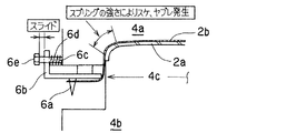
この表皮保持機構6は、表皮2bを突き刺すセットピン6aを有するスライドプレート6bが図15中矢印方向にスライド可能なようにガイドピン6cによりスライド自在に支持され、かつ外方に向けてスライドプレート6bを付勢するようにガイドピン6cの外周にコイルスプリング6dが巻装されている。尚、図中符号6eはスライドプレート6bを基準位置に位置決めするストッパーを示す。
【0006】
そして、図16に示すように、成形下型4bにおけるコア部4cの外周の3辺にそれぞれスライドプレート6bが設けられ、スライドプレート6bの両側がガイドピン6cによりスライド自在に支持されている。
【0007】
上記成形装置4を使用して、ドアトリムアッパー2を成形するには、成形上下型4a,4b内に表皮搬送板5を介して表皮2bを投入した後、表皮2bの周縁部分を表皮保持機構6により保持した状態で成形上型4aが下降し、所定ストローク下降したとき樹脂芯材2aの素材である溶融樹脂が成形型4a,4b内に供給され、樹脂芯材2aが所要形状にモールドプレス成形されるが、このとき、図17に示すように、表皮2bが製品形状に追従するように、成形型4a,4b内に引き込まれるため、表皮保持機構6におけるスライドプレート6bがコイルスプリング6dのバネ圧に対して中央側(成形型4a,4b側)にスライドすることにより、表皮2bに適度なテンションが付与され、樹脂芯材2aと表皮2bとが一体成形される。
【0008】
【発明が解決しようとする課題】
このように、樹脂芯材2aと表皮2bとを一体にモールドプレス成形する際、従来工法では、表皮2bを表皮保持機構6により保持して、表皮2bに成形型4a,4bからテンションが加わった際、コイルスプリング6dのバネ圧との平衡作用で表皮2bに適切なテンションが加わるようにしているが、図18に示すように、モールドプレス成形時、表皮2bに加わるテンションは部位毎に差異があるため、例えばF1>F2であれば、一方側のコイルスプリング6dのバネ圧を他方側のコイルスプリング6d´のバネ圧よりも小さく設定しなければ、F1に対応して表皮2bが成形型4a,4b内に滑り込まず、表皮2bに過度のテンションが加わる原因となる。
【0009】
従って、表皮保持機構6におけるコイルスプリング6dのバランス調整を適切に行なわなければならないという問題点が指摘されている。
【0010】
特に、最近多用されるTPOシートは成形時、樹脂芯材2aの素材である溶融樹脂の熱による影響を受け易く、コイルスプリング6dの強さを適切に設定しないとコイルスプリング6dによる過度のバネ圧により表皮2bに透けや破れ等が発生し易いという傾向にある。
【0011】
更に、従来工法では、コイルスプリング6dのバネ圧を調整することにより、表皮2bに適切なテンションを付与することは可能であるが、表皮2bが成形型4a,4b内に滑り込むタイミングは、表皮2bに加わるテンションがコイルスプリング6dのバネ圧を上廻ったときであり、表皮2bの滑り込みのタイミングはコイルスプリング6dのバネ圧に左右され、適切なタイミングを選択できないでいるのが実情である。
【0012】
この表皮2bが成形型4a,4b内に滑り込むタイミングは、例えば、製品形状に着目した場合、製品凸部面と製品凹部面を比べれば、製品凸部面では表皮2bの成形型4a,4b内への滑り込みが早く行なわれることが望ましく、その逆に製品凹部面については比較的遅い時期に滑り込みを開始したほうが熱の影響を受け難いことから好ましい。
【0013】
この発明は、このような事情に鑑みてなされたもので、モールドプレス成形工法により樹脂芯材と表皮とを一体成形してなる積層成形体の成形方法及び成形装置であって、成形時、表皮が型面形状に追従する際、表皮が成形型内に滑り込む量を適切に制御することにより表皮に適切なテンションを付与することができるとともに、所望ならば、表皮が成形型内に滑り込むタイミングを制御することにより、成形性に優れた積層成形体が得られる積層成形体の成形方法及び成形装置を提供することを目的としている。
【0014】
【課題を解決するための手段】
上記目的を達成するために、この出願の請求項1に記載の発明は、樹脂芯材の表面に表皮を一体貼着してなる積層成形体の成形方法であって、成形上型に設けた表皮保持機構により表皮の周縁部の全長、あるいはその一部を保持した後、成形上型を下降させて、成形下型のコア部外周に設けられているカムスライド機構と表皮保持機構とのカム作用により、表皮保持機構を成形下型側に向けてスライド動作させ、樹脂芯材の成形時、表皮が製品形状に応じて成形上下型の型面に追従する際、表皮に適切なテンションを付与することを特徴とする。
【0015】
ここで、成形工法としては、モールドプレス成形工法、コールドプレス成形工法などが挙げられる。モールドプレス成形工法においては、成形型内に表皮をセットした後、射出成形機からマニホールド、ゲートを通じて成形下型の型面に溶融樹脂を分配供給し、モールドプレス成形上下型を型締めすることにより、樹脂芯材と表皮とを一体成形する。
【0016】
また、コールドプレス成形工法においては、樹脂芯材の素材としての熱可塑性樹脂板をTダイ押出成形機によりシート状に押し出し、このシート原反をヒーターにより加熱軟化処理した後、コールドプレス成形下型にセットし、その後、成形型内に供給されるシート状の表皮とともにコールドプレス成形により樹脂芯材と表皮とを一体成形する。
【0017】
そして、請求項1に記載の発明によれば、成形上型の下降動作と共に表皮の周縁を保持する表皮保持機構も下降し、成形型の型面形状に追従するように表皮にテンションが加わるが、その際、表皮保持機構と成形下型のコア部外周に設けられているカムスライド機構との連繋により、表皮保持機構がカムスライド機構におけるカムブロックの傾斜カム面に沿ってガイドされ、表皮保持機構が成形型に接近する方向に引き寄せられるため、成形型内に表皮が引き込まれ(滑り込み)、表皮に過度のテンションが加わることなく、適切なテンションを表皮に付与することができる。
【0018】
この出願の請求項2に記載の発明は、カムスライド機構におけるカムブロックの傾斜カム面の傾斜角度を調整することにより、表皮保持機構が傾斜カム面にガイドされるスライドストローク量を可変させて、表皮に適切なテンションを付与することを特徴とする。
【0019】
そして、請求項2に記載の発明によれば、カムスライド機構におけるカムブロックに形成される傾斜カム面の傾斜角度が部位により相違するように設定されているため、例えば、鉛直軸を基準として傾斜角度を急角度に設定した場合は、表皮保持機構がカムスライド機構によりガイドされるスライドストローク量が小さく抑えられることから、成形型内に引き込まれる表皮の量が小さくても適切なテンションが得られる。逆に、鉛直軸を基準として傾斜角度を緩やかに設定した場合は、表皮保持機構のスライドストローク量が大きく、表皮の成形型内への引き込み量を多く確保でき、適切なテンションを表皮に付与できる。このように、製品形状に応じてカムスライド機構における傾斜カム面の傾斜角度を相違させることにより、表皮の全体に亘り適切なテンションを付与できる。
【0020】
この出願の請求項3に記載の発明は、カムスライド機構におけるカムブロックの上下位置を調整することにより、表皮保持機構がカムブロックの傾斜カム面上をスライド動作する動作タイミングを制御することを特徴とする。
【0021】
そして、請求項3に記載の発明によれば、カムブロックの前後方向位置(成形型と接離する方向)並びに上下方向位置の双方、あるいは一方を可変できるため、例えばカムスライド機構におけるカムブロックを前方(成形型に近接する方向)位置、あるいは上方位置に設定した場合は、表皮保持機構のスライド動作タイミングが早まり、特に、製品形状に深絞り凸部を設定したとき等のテンション調整に有効である。
【0022】
また、後方(成形型から離れる方向)位置、あるいは下方位置にカムブロックを設けた場合は、表皮保持機構の動作を遅らせることができ、比較的製品形状が単純形状であるときのテンション調整に有効であるとともに、樹脂熱の悪影響を有効に排除できる。
【0023】
次いで、この出願の請求項4に記載の発明は、樹脂芯材の表面に表皮を一体貼着する成形上下型と、成形上型の外周部の全周、あるいはその一部に設けられ、表皮の周縁部の全周、あるいはその一部を保持する表皮保持機構を備えた積層成形体の成形装置であって、上記表皮保持機構は、表皮の周縁を仮止めするセットピンを有するスライドプレートが成形上型と接離する方向にスライド自在でかつ外側方向に向けてバネ付勢され成形上型に支持されているとともに、成形下型のコア部外周には、成形上型の下降動作と一体に下降する表皮保持機構を斜面カム機構により成形型側にスライドさせるカムスライド機構が設けられていることを特徴とする。
【0024】
ここで、表皮保持機構としては、セットピンを備え、かつ成形上型に対して接離する方向にスライド可能に成形上型に支持されるスライドプレートと、このスライドプレートを常時成形型から離間する方向に付勢するコイルスプリング等のバネ手段が設けられていれば良い。一方、カムスライド機構は、成形下型のコア部外周の任意箇所に設けられており、カムスライド機構は、傾斜カム面を有するカムブロックからなる。
【0025】
そして、請求項4に記載の発明によれば、積層成形体の製品形状に即して表皮に付加するテンションを調整する必要があるが、成形上型に設けた表皮保持機構は、成形下型の下降動作と同時に下降し、表皮保持機構がカムスライド機構の傾斜カム面に当接し、その後、成形上型が下降を続行すれば、表皮保持機構は傾斜カム面に沿って成形型に近づくように可動するため、成形時、表皮に加わる過度のテンションは、表皮が成形型内に引き込まれる(滑り込む)ことにより緩和され、表皮に適切なテンションを付与できる。
【0026】
そして、従来のように、コイルスプリングのバネ圧をバランス良く調整するのに比べて、同一のコイルスプリングを使用できるため、従来必要としたコイルスプリングのバランス調整という煩雑な作業を廃止できる。
【0027】
この出願の請求項5に記載の発明は、カムスライド機構は、斜面カムとして作用する傾斜カム面を形成したカムブロックからなり、上記傾斜カム面の傾斜角度は、表皮にプレス成形時に加わるテンションに応じて差異をもたせて設定されていることを特徴とする。
【0028】
この出願の請求項6に記載の発明は、カムスライド機構における傾斜カム面には、傾斜カム板が回動可能に取り付けられており、アジャスタボルトの操作により傾斜カム板の傾斜角度を調整できるようにしたことを特徴とする。
【0029】
この出願の請求項7に記載の発明は、カムスライド機構における傾斜カム面の傾斜角度を調整できるように、カムブロックを支持する角度調整台が配設されていることを特徴とする。
【0030】
そして、請求項5乃至7に記載の発明によれば、カムスライド機構における傾斜カム面の傾斜角度を相違させるか、あるいは傾斜カム面を構成する回動可能な傾斜カム板の設定角度を調整するか、あるいはカムブロックを支持する角度調整台の角度調整を行なうことにより、表皮保持機構がガイドされる傾斜カム面の角度を可変することができ、複雑な製品形状の部位は傾斜角度を緩やかに設定する一方、単純形状の部位は傾斜角度を急角度に設定すれば、表皮の成形型内への引き込み量(滑り込み量)に見合った適切なテンションを表皮に付与することができる。
【0031】
この出願の請求項8に記載の発明は、カムスライド機構におけるカムブロックの下面には、カムブロックの前後位置、上下位置を調整できる前後方向駆動機構又は及び上下方向駆動機構が設けられていることを特徴とする。
【0032】
そして、請求項8に記載の発明によれば、カムスライド機構のカムブロックは、前後方向(成形下型と接離する方向)及び又は上下方向に位置調整が可能な前後方向駆動手段、上下方向駆動手段が設けられているため、カムブロックを前方位置、あるいは上方位置に設定した場合、表皮保持機構の動作タイミングを早めることができ、逆に後方位置、あるいは下方位置にカムブロックを設定すれば、表皮保持機構の動作タイミングを遅らせることができ、製品形状に合わせて成形型内に表皮を滑り込ませるタイミングを任意に設定できる。
【0033】
【発明の実施の形態】
以下、本発明に係る積層成形体の成形方法及び成形装置の実施形態について、添付図面を参照しながら詳細に説明する。
【0034】
図1,図2は本発明を上下2分割構成の自動車用ドアトリムにおけるドアトリムアッパーに適用した具体例を示す自動車用ドアトリムの正面図並びに断面図、図3は上記ドアトリムアッパーの成形に使用する本発明に係る成形装置の一実施形態を示す全体図、図4は図3に示す成形装置における表皮保持機構とカムスライド機構の配置を示す説明図、図5は同成形装置におけるカムスライド機構の使用形態を示す説明図、図6は本発明に係る成形装置を使用してドアトリムアッパーを成形する成形方法における表皮セット工程を示す説明図、図7は同成形方法におけるモールドプレス成形工程を示す説明図、図8はモールドプレス成形時、表皮に加わるテンション状態を示す説明図、図9は本発明に係る成形装置の別実施形態の構成を示す説明図、図10は図9に示す成形装置におけるカムスライド機構の構成説明図、図11乃至図13は本発明に係る成形装置におけるカムスライド機構の更に別実施形態を示す各説明図である。
【0035】
図1,図2において、本発明に係る積層成形体の一実施形態であるドアトリムアッパーの具体例について説明する。まず、自動車用ドアトリム10は、ドアトリムアッパー11とドアトリムロア12との上下2分割体から構成されており、ドアトリムアッパー11は所望の曲面形状に成形された樹脂芯材11aの表面に表皮11bを一体貼着してなる積層成形体から構成されており、ドアトリムロア12は、合成樹脂の射出成形体からなりドアポケット12a及びスピーカグリル12b等が一体成形されている。
【0036】
更に詳しくは、ドアトリムアッパー11を構成する樹脂芯材11a並びに表皮11bの具体的な構成としては、樹脂芯材11aは、タルクを混入したPP(ポリプロピレン)樹脂をモールドプレス成形することにより、所望の曲面形状に成形されており、表皮11bは、サーモプラスチックエラストマーの一例であるTPO(サーモプラスチックオレフィン)シートの裏面にポリエチレンフォームを裏打ちしてなるクッション性並びに手触り感、外観性能に優れた積層シート材料を素材として、表皮11bを予めモールドプレス成形型内にセットしておき、樹脂芯材11aのモールドプレス成形時に樹脂芯材11aと表皮11bとを一体プレス成形している。
【0037】
尚、参考までにドアトリムアッパー11とドアトリムロア12との接合構造について説明すると、ドアトリムロア12の上縁に横方向に沿って所定ピッチ間隔で裏面側から取付用ボス13を突設形成し、それと対応するようにドアトリムアッパー11の下縁に取付孔14が開設され、取付用ボス13を取付孔14内に挿入して、取付用ボス13の先端側を熱溶着、あるいは超音波溶着等によりカシメ加工することにより、ドアトリムアッパー11とドアトリムロア12とを簡単に接合固定している。
【0038】
ところで、本発明は、上記自動車用ドアトリム10におけるドアトリムアッパー11のように、樹脂芯材11aと表皮11bとの積層成形体において、プレス成形時、表皮11bに適正なテンションを付与し、良好な成形性が得られ、シワ、弛み、破れ等の成形不良を可及的に防止でき、外観性能に優れた積層成形体(ドアトリムアッパー11)の成形方法並びに成形装置を提供することが特徴である。
【0039】
次いで、上記自動車用ドアトリム10におけるドアトリムアッパー11の成形工法として、モールドプレス成形工法を用いた実施形態について、図3乃至図8に基づいて説明する。まず、図3は本発明方法を使用する際の成形装置20の全体図、図4は同成形装置20における表皮保持機構とカムスライド機構との配置を示す説明図であり、図5はカムスライド機構の使用形態の説明図である。
【0040】
図3に基づいて、成形装置20の具体的な構成について説明すると、本発明に係る成形装置20は、所定ストローク上下動可能な成形上型30と、成形上型30と対をなす固定側の成形下型40と、成形上型30の全周、あるいはその一部に設けられている表皮保持機構50と、表皮保持機構50に対応して成形下型40のコア部40aの外周に設けられているカムスライド機構60とから大略構成されている。
【0041】
更に詳しくは、成形上型30は昇降用シリンダ31により所定ストローク上下動可能であり、それに対応する成形下型40は、図示はしないが射出成形機が隣接設置され、この射出成形機から供給される溶融樹脂がマニホールド41、ゲート42を通じて成形下型40の型面上に分配供給されるという構成である。
【0042】
また、この成形下型40内には、エジェクタプレート43が設けられており、このエジェクタプレート43の上昇動作により、エジェクタピン44を上昇動作して、プレス成形後のドアトリムアッパー11を脱型操作できる。尚、上述した成形上下型30,40は、ドアトリムアッパー11の製品形状に即したキャビティ部30aとコア部40aを備えている。
【0043】
次いで、表皮保持機構50は、図3,図4に示すように、断面L字状の長尺体からなるスライドプレート51が成形上型30の周囲4辺のうち3辺(ドアトリムアッパー11の上縁と両側縁)に沿って成形上型30に水平方向に沿ってスライド可能に支持されており、このスライドプレート51の下面には、表皮11bをセットするセットピン52が長手方向に沿って所定ピッチ間隔で設けられており、スライドプレート51の垂直状部51aの両端側に支持孔53が開設され、成形上型30の側壁面から外方に向けて延びるガイドピン54がこの支持孔53内に挿通されてガイドピン54の外周にコイルスプリング55を介装することにより、スライドプレート51は常時外方に向けてバネ付勢され、ガイドピン54先端のストッパー56によりスライドプレート51の外側方向への動きが規制されている。
【0044】
次に、成形下型40のコア部40aの外周に沿って設けられるカムスライド機構60は、表皮保持機構50におけるスライドプレート51の両端側に並置され、本実施形態では図4に示すように、6箇所にそれぞれカムスライド機構60a〜60fが設けられている。各カムスライド機構60は、カムブロック61の成形下型40と対向する側に傾斜カム面62が形成されている。
【0045】
そして、本発明装置20においては、並設される2台のカムスライド機構60a,60bについて例示すれば、図5(a)に示すように、一方側のカムスライド機構60aについては傾斜カム面62aの傾斜角度θ1が比較的急な角度で設定され、また、図5(b)に示すように、他方側のカムスライド機構60bについては傾斜カム面62bは角度θ2の比較的緩やかな傾斜角度を備えている。
【0046】
この傾斜カム面62の傾斜角度を相違させることは、後述するように、モールドプレス成形時、表皮11bに加わるテンション調整に有効である。すなわち、製品形状が深絞り部分となる箇所に相当する表皮11bを保持する部分のカムスライド機構60bにおける傾斜カム面62bの傾斜角度を緩やかに設定する一方、比較的単純形状部分の表皮11bに対応するカムスライド機構60aは傾斜カム面62aの傾斜角度が急角度に設定されている。
【0047】
また、他のカムスライド機構60c〜60fについては、ドアトリムアッパー11の造形状を考慮して、カムスライド機構60c,60dについては、カムスライド機構60cに比べカムスライド機構60dの傾斜カム面62dの傾斜角度を緩やかに設定するとともに、カムスライド機構60e,60fについては、カムスライド機構60fにおける傾斜カム面62fをカムスライド機構60eの傾斜カム面62eよりも傾斜角度が緩やかに設定されている。
【0048】
従って、本発明に係る成形装置20は、成形上型30の外周部に設けられる表皮保持機構50は、コイルスプリング55のバネ圧は全て等しく設定されており、従来のように部位毎にコイルスプリング55のバネ圧を調整する構成ではないため、従来煩雑であったコイルスプリングのバランス調整を不要にできる。
【0049】
次いで、図6乃至図8に基づいて、本発明方法の各工程について説明すると、図6に示すように、成形上下型30,40が型開き状態にあるとき、成形上下型30,40内に表皮搬送板32を投入し、次いで、表皮搬送板32に内装されるシリンダ(図示せず)の上下動作により、表皮搬送板32に載置されている表皮11bを成形上型30の周縁部に設けられている表皮保持機構50のセットピン52に食い込ませて、表皮11bの仮セットを行なう。
【0050】
更に、表皮11bの仮セットが終了すれば、表皮搬送板32が成形型30,40内から退避し、成形上型30が昇降用シリンダ31の動作により所定ストローク下降動作を始める。
【0051】
そして、成形上下型30,40の型間クリアランスが10〜30mmの段階で一旦成形上型30が停止して、射出成形機から供給する溶融樹脂がマニホールド41、ゲート42を通じて成形下型40の型面上に分配供給され、その後、成形上型30が更に下降動作を継続して行ない、図7に示すように、樹脂芯材11aと表皮11bとを所要形状にモールドプレス成形して、図1,図2に示すドアトリムアッパー11の成形が完了する。
【0052】
そして、この一連の成形上型30の動作時、表皮11bを保持する表皮保持機構50も下降するが、スライドプレート51のコーナー部51bがカムスライド機構60における傾斜カム面62に当接した後は、斜面カム作用によりスライドプレート51は下降動作と並行して、成形下型40側に向けて横方向にスライドするようにガイドされるため、図7中符号dで示すスライドストローク量が得られ、このスライドストローク量dに応じて成形上下型30,40のプレス成形時、成形型30,40内に表皮11bが有効に引き込まれ、過度のテンションが加わることがないため、表皮11bに透け、破れ等が発生することがない。
【0053】
そして、本発明方法においては、カムスライド機構60における傾斜カム面62は、各カムスライド機構60a〜60fにおいて全て同一の傾斜角度ではなく、ドアトリムアッパー11の製品形状に即して、展開率の高い部分の表皮11bは成形時、過度のテンションが作用し、それを相殺するため、表皮11bを成形型30,40内に充分滑り込ませる必要があることから、表皮保持機構50のスライドストローク量が多く設定されている。
【0054】
すなわち、図8に示すように、カムスライド機構60a〜60fに対応する表皮保持機構50の各スライドストローク量をd1〜d6とした場合、ドアトリムアッパー11の造形上、d1<d2また、d3<d4、d5<d6に設定する必要があるため、上述した通り、カムスライド機構60a〜60fの各傾斜カム面62a〜62fについては、62b、62d、62fの傾斜角度を緩やかに設定した。
【0055】
このように、カムスライド機構60の傾斜カム面62の傾斜角度を適宜調整することにより、プレス成形時、表皮11bに加わるテンションを適切に調整することができるため、表皮11bの透け、破れ、シワ等が発生することがなく、成形性に優れたドアトリムアッパー11の成形が可能となる。
【0056】
次いで、図9乃至図13は、本発明に係る成形装置20に使用するカムスライド機構60の別実施形態を示すもので、成形上下型30,40及び表皮保持機構50の構成は上述した実施形態と同一であるため、その詳細な説明は省略する。
【0057】
まず、図9,図10に示すカムスライド機構60は所定の傾斜角度を有する傾斜カム面62を有するカムブロック61に前後方向駆動機構70と上下方向駆動機構80とが付設されている。
【0058】
そして、前後方向駆動機構70を動作させることにより、カムブロック61をA、B方向にスライド動作可能とする。例えば、A方向、すなわち成形下型40から離間する方向にカムブロック61を移動させることにより、モールドプレス成形時、表皮保持機構50のスライドプレート51がカムスライド機構60の傾斜カム面62に当接する時期を遅らせることができ、製品の展開率が小さい部位の表皮11bのテンション調整に有効である。
【0059】
逆に、B方向にカムブロック61を移動させれば、表皮保持機構50のスライドプレート51が傾斜カム面62に早く当接して、表皮保持機構50の動作が早まるため、展開率が大きい部位で特に製品面の深絞り凸部に対応する表皮11bのテンション調整に適している。
【0060】
また、カムブロック61を上下方向駆動機構80を駆動させてC、D方向に移動させることもできる。この場合、C方向にカムブロック61を上昇動作させれば、表皮保持機構50との連繋動作が早まるため、カムブロック61をB方向にスライドさせたときと同様、展開率が大きい部位の表皮11bのテンション調整に有効であり、逆にD方向、すなわちカムブロック61を下方向に移動させれば、カムブロック61をA方向にスライドさせたときと同様、それだけ表皮保持機構50のスライド動作を遅らせることができるため、展開率が小さい部位の表皮11bのテンション調整に適している。
【0061】
そして、参考までに前後方向駆動機構70及び上下方向駆動機構80の具体例を図10に基づいて説明すると、前後方向駆動機構70は、パルスモーター71により、回転軸72が回転駆動され、カムブロック61の下面にナット73及び軸受74が取り付けられ、回転軸72はナット73、軸受74並びに支持軸受75に挿通支持され、ナット73に対応する回転軸72にネジ部76が設けられていれば、パルスモーター71の駆動により、送りネジ機構を利用して、カムブロック61をA、B方向にスライド動作させることができる。尚、この送り機構に替えてシリンダを利用してカムブロック61を前後方向に駆動させることもできる。
【0062】
一方、カムブロック61の上下駆動機構として、駆動用シリンダ81により、支持プレート82を所定ストローク上下動可能とし、この支持プレート82に上述した前後駆動機構70のパルスモーター71、支持軸受75並びにカムブロック61が支持されている。尚、カムブロック61の前後方向駆動機構70及び上下方向駆動機構80は、図10に示す具体例に限定されるものではなく、慣用の駆動機構を代替しても良い。
【0063】
次いで、図11乃至図13は、カムスライド機構60におけるカムブロック61の傾斜カム面62の傾斜角度を変更する別実施形態を示すもので、図11に示すように、カムブロック61に傾斜カム板63を回動軸64を基に回動可能に取り付け、アジャスタボルト65により傾斜カム板63を支持するという構成である。
【0064】
従って、アジャスタボルト65のネジ込み操作、あるいは緩める操作により、図中E、F方向に傾斜カム板63を回動操作でき、アジャスタボルト65を締め付けて、傾斜カム板63をE方向に回動操作すれば、表皮保持機構50のスライドストローク量を多く確保できるため、展開率が大きい部位での表皮11bのテンション調整に有効であり、逆に、アジャスタボルト65を緩めてF方向に回動操作すれば、表皮保持機構50のスライドストローク量が小さくなるため、展開率が小さい単純形状の部位での表皮11bのテンション調整に有効である。
【0065】
また、図12に示すように、カムスライド機構60におけるカムブロック61を角度調整台66上に載置する構造とし、角度調整台66の角度(図中αで示す)を変更することにより、図中G、H方向に傾きを変更することができる。
【0066】
そして、角度調整台66の角度αを大きく設定してG方向に傾きを変えた場合、表皮保持機構50のスライドストローク量を多くとれ、展開率の大きい部位での表皮11bのテンション調整に有効であり、逆に角度調整台66の角度αを小さく設定して、H方向に傾きを変えた場合、表皮保持機構50のスライドストローク量を小さく抑えることができ、展開率が小さい部位での表皮11bのテンション調整に有効である。
【0067】
次いで、図13に示すように、角度調整台66上に沿ってカムブロック61を前後方向にスライド動作させれば、カムブロック61を上下方向に位置させることができ、表皮保持機構50におけるスライド動作のタイミングを調整することができる。
【0068】
以上説明した実施形態は、上下2分割方式の自動車用ドアトリム10におけるドアトリムアッパー11に適用した実施形態であるが、一体型のドアトリムやドアトリム以外のリヤコーナートリム等の内装部品一般に適用できる。
【0069】
また、樹脂芯材11aと表皮11bとをコールドプレス成形工法により一体プレス成形する工法に適用することもできる。
【0070】
【発明の効果】
以上説明した通り、本発明に係る積層成形体の成形方法及び成形装置は、成形上型に設けた表皮保持機構により表皮の周縁を保持した状態で成形上型を下降操作すれば、成形下型の外周に設けたカムスライド機構に対して表皮保持機構が連繋動作し、表皮保持機構が下降動作と並行して成形下型に向けて所定ストロークスライド動作を行ない、プレス成形時、表皮に過度のテンションが作用しても、成形型内に表皮が滑り込み、表皮に適切なテンションを付与することができるため、表皮の透け、シワ、破れ等の成形不良が発生することがなく、成形性を高めた外観性能に優れた積層成形体を成形できるという効果を有する。
【0071】
更に、カムスライド機構における傾斜カム面の傾斜角度及び又は傾斜カム面の前後位置、あるいは上下位置をそれぞれ調整することにより、表皮保持機構のスライド動作タイミング及びスライドストローク量を適宜調整できるため、積層成形体の形状や表皮の材質に左右されることなく、造形自由度を高めるとともに、材料自由度を拡大させることができるという効果を有する。
【図面の簡単な説明】
【図1】本発明に係る積層成形体の一実施形態である自動車用ドアトリムを示す正面図である。
【図2】図1中II−II線断面図である。
【図3】本発明に係る積層成形体の成形装置の一実施形態を示す全体図である。
【図4】図3に示す成形装置における表皮保持機構とカムスライド機構との配置構成を示す説明図である。
【図5】図3に示す成形装置におけるカムスライド機構の使用形態を示す説明図である。
【図6】本発明に係る積層成形体の成形方法における表皮セット工程を示す説明図である。
【図7】本発明に係る積層成形体の成形方法におけるモールドプレス成形工程を示す説明図である。
【図8】本発明方法におけるモールドプレス成形工程における表皮へのテンション調整状態を示す説明図である。
【図9】本発明に係る積層成形体の成形装置の別実施形態を示す説明図である。
【図10】図9に示すカムスライド機構の前後方向駆動機構並びに上下方向駆動機構を示す構成説明図である。
【図11】本発明に係る成形装置におけるカムスライド機構の更に別実施形態を示す説明図である。
【図12】本発明に係る成形装置におけるカムスライド機構の更に別実施形態を示す説明図である。
【図13】本発明に係る成形装置におけるカムスライド機構の更に別実施形態を示す説明図である。
【図14】従来の自動車用ドアトリムの構成を示す断面図である。
【図15】従来のドアトリムアッパーの成形方法における表皮のセット工程を示す説明図である。
【図16】従来の成形装置における表皮保持機構の配置構成を示す説明図である。
【図17】従来のドアトリムアッパーの成形方法におけるモールドプレス成形工程を示す説明図である。
【図18】従来のモールドプレス成形工程における表皮に加わるテンションを示す説明図である。
【符号の説明】
10 自動車用ドアドアトリム
11 ドアトリムアッパー
11a 樹脂芯材
11b 表皮
12 ドアトリムロア
20 成形装置
30 成形上型
31 昇降用シリンダ
32 表皮搬送板
40 成形下型
41 マニホールド
42 ゲート
43 エジェクタプレート
44 エジェクタピン
50 表皮保持機構
51 スライドプレート
52 セットピン
53 支持孔
54 ガイドピン
55 コイルスプリング
56 ストッパー
60(60a〜60f) カムスライド機構
61 カムブロック
62 傾斜カム面
63 傾斜カム板
64 回動軸
65 アジャスタボルト
66 角度調整台
70 前後方向駆動機構
71 パルスモーター
72 回動軸
73 ナット
74,75 軸受
76 ネジ部
80 上下方向駆動機構
81 駆動シリンダ
82 支持プレート[0001]
BACKGROUND OF THE INVENTION
The present invention relates to a molding method and a molding apparatus for a laminated molded body in which a skin is integrally bonded to the surface of a resin core material, and in particular, when a resin core material and a skin are integrally molded, an appropriate tension is applied to the skin. It is related with the shaping | molding method and shaping | molding apparatus of a laminated molded object which enabled shaping | molding of the laminated molded article excellent in the moldability by doing.
[0002]
[Prior art]
FIG. 14 is a cross-sectional view showing a configuration of an automotive door trim mounted on the indoor side of the door panel. The
[0003]
Then, when molding the door trim upper 2 which is a laminated molded body of the
[0004]
A
[0005]
This skin holding mechanism 6 is slidably supported by a
[0006]
And as shown in FIG. 16, the
[0007]
In order to mold the door trim upper 2 using the
[0008]
[Problems to be solved by the invention]
As described above, when the
[0009]
Therefore, it has been pointed out that the balance adjustment of the
[0010]
In particular, TPO sheets that are frequently used recently are easily affected by the heat of the molten resin, which is the material of the
[0011]
Further, in the conventional method, it is possible to apply an appropriate tension to the
[0012]
The timing at which the
[0013]
The present invention has been made in view of such circumstances, and is a molding method and a molding apparatus for a laminated molded body in which a resin core material and a skin are integrally molded by a mold press molding method. When following the mold surface shape, it is possible to apply an appropriate tension to the skin by appropriately controlling the amount of the skin sliding into the mold, and if desired, the timing at which the skin slides into the mold. It aims at providing the shaping | molding method and shaping | molding apparatus of a laminated molded object from which the laminated molded object excellent in the moldability is obtained by controlling.
[0014]
[Means for Solving the Problems]
In order to achieve the above object, the invention according to
[0015]
Here, examples of the molding method include a mold press molding method and a cold press molding method. In the mold press molding method, after the skin is set in the mold, molten resin is distributed and supplied from the injection molding machine to the mold surface of the lower mold through the manifold and gate, and the upper and lower molds of the mold press molding are clamped. The resin core material and the skin are integrally formed.
[0016]
In the cold press molding method, a thermoplastic resin plate as a material of the resin core material is extruded into a sheet shape by a T-die extrusion molding machine, and this sheet raw fabric is heated and softened by a heater, and then a cold press molded lower mold After that, the resin core material and the skin are integrally formed by cold press molding together with the sheet-like skin supplied into the mold.
[0017]
According to the first aspect of the present invention, the skin holding mechanism that holds the periphery of the skin is lowered along with the lowering operation of the molding upper die, and tension is applied to the skin so as to follow the mold surface shape of the molding die. In that case, the skin holding mechanism is guided along the inclined cam surface of the cam block in the cam slide mechanism by the linkage of the skin holding mechanism and the cam slide mechanism provided on the outer periphery of the core portion of the molding lower mold, and the skin holding Since the mechanism is pulled in the direction approaching the mold, the skin is drawn into the mold (sliding), and an appropriate tension can be applied to the skin without applying excessive tension to the skin.
[0018]
In the invention according to
[0019]
According to the second aspect of the present invention, since the inclination angle of the inclined cam surface formed on the cam block in the cam slide mechanism is set to be different depending on the part, for example, the inclination is based on the vertical axis. When the angle is set to a steep angle, the slide holding amount of the skin holding mechanism guided by the cam slide mechanism can be kept small, so that an appropriate tension can be obtained even if the amount of skin drawn into the mold is small. . Conversely, when the inclination angle is set gently with respect to the vertical axis, the amount of sliding stroke of the skin holding mechanism is large, so that a large amount of skin can be drawn into the mold, and appropriate tension can be applied to the skin. . In this way, by varying the inclination angle of the inclined cam surface in the cam slide mechanism according to the product shape, an appropriate tension can be applied over the entire skin.
[0020]
The invention according to
[0021]
According to the third aspect of the present invention, since either or both the front-rear direction position of the cam block (the direction in which it is in contact with and away from the mold) and the vertical position can be varied, for example, the cam block in the cam slide mechanism When it is set to the front (direction close to the mold) or the upper position, the sliding movement timing of the skin holding mechanism is advanced, which is particularly effective for tension adjustment when a deep drawing convex part is set in the product shape. is there.
[0022]
In addition, if a cam block is provided at the rear position (in the direction away from the mold) or at a lower position, the operation of the skin holding mechanism can be delayed, which is effective for tension adjustment when the product shape is relatively simple. In addition, the adverse effects of resin heat can be effectively eliminated.
[0023]
Next, the invention described in
[0024]
Here, as the skin holding mechanism, there is provided a set pin and a slide plate that is supported by the molding upper die so as to be slidable in the direction of contact with and separating from the molding upper die, and this slide plate is always separated from the molding die. Spring means such as a coil spring that biases in the direction may be provided. On the other hand, the cam slide mechanism is provided at an arbitrary position on the outer periphery of the core portion of the molded lower mold, and the cam slide mechanism is composed of a cam block having an inclined cam surface.
[0025]
According to the invention described in
[0026]
And since the same coil spring can be used compared with adjusting the spring pressure of a coil spring with good balance like before, the complicated work of balance adjustment of a coil spring required conventionally can be abolished.
[0027]
In the invention according to
[0028]
In the invention according to claim 6 of the present application, an inclined cam plate is rotatably attached to the inclined cam surface of the cam slide mechanism so that the inclination angle of the inclined cam plate can be adjusted by operating an adjuster bolt. It is characterized by that.
[0029]
The invention described in claim 7 of this application is characterized in that an angle adjusting table for supporting the cam block is provided so that the inclination angle of the inclined cam surface in the cam slide mechanism can be adjusted.
[0030]
According to the fifth to seventh aspects of the invention, the inclination angle of the inclined cam surface in the cam slide mechanism is made different, or the set angle of the rotatable inclined cam plate constituting the inclined cam surface is adjusted. Alternatively, by adjusting the angle of the angle adjusting table that supports the cam block, the angle of the inclined cam surface on which the skin holding mechanism is guided can be varied. On the other hand, if the inclination angle is set to a steep angle in a simple-shaped portion, an appropriate tension corresponding to the amount of the skin drawn into the mold (sliding amount) can be applied to the skin.
[0031]
In the invention according to claim 8 of this application, a front-rear direction drive mechanism or a vertical direction drive mechanism capable of adjusting the front-rear position and the vertical position of the cam block is provided on the lower surface of the cam block in the cam slide mechanism. It is characterized by.
[0032]
According to the eighth aspect of the present invention, the cam block of the cam slide mechanism has a front-rear direction drive means capable of adjusting the position in the front-rear direction (direction in contact with and away from the molding lower mold) and / or the vertical direction, Since the drive means is provided, when the cam block is set to the front position or the upper position, the operation timing of the skin holding mechanism can be advanced, and conversely, if the cam block is set to the rear position or the lower position, The operation timing of the skin holding mechanism can be delayed, and the timing for sliding the skin into the mold according to the product shape can be arbitrarily set.
[0033]
DETAILED DESCRIPTION OF THE INVENTION
DESCRIPTION OF EMBODIMENTS Hereinafter, embodiments of a method for molding a laminated molded body and a molding apparatus according to the present invention will be described in detail with reference to the accompanying drawings.
[0034]
1 and 2 are a front view and a sectional view of an automobile door trim showing a specific example in which the present invention is applied to a door trim upper in an automotive door trim having a vertically divided structure. FIG. 3 is a diagram of the present invention used for molding the door trim upper. FIG. 4 is an explanatory view showing the arrangement of the skin holding mechanism and the cam slide mechanism in the molding apparatus shown in FIG. 3, and FIG. 5 is a usage pattern of the cam slide mechanism in the molding apparatus. FIG. 6 is an explanatory diagram showing a skin setting step in a molding method for molding a door trim upper using the molding apparatus according to the present invention, FIG. 7 is an explanatory diagram showing a mold press molding step in the molding method, FIG. 8 is an explanatory view showing a tension state applied to the skin during mold press molding, and FIG. 9 is an explanatory view showing a configuration of another embodiment of the molding apparatus according to the present invention. FIG, 10 is diagram illustrating the configuration of a cam slide mechanism in the molding apparatus shown in FIG. 9, FIGS. 11 to 13 are each explanatory views showing still another embodiment of the cam slide mechanism in the molding apparatus according to the present invention.
[0035]
1 and 2, a specific example of a door trim upper which is an embodiment of the laminated molded body according to the present invention will be described. First, the automobile door trim 10 is composed of an upper and lower divided body of a door trim upper 11 and a door trim lower 12, and the door trim upper 11 is integrally formed with a
[0036]
More specifically, as a specific configuration of the
[0037]
For reference, the joint structure between the door trim upper 11 and the door trim lower 12 will be described. A mounting
[0038]
By the way, in the present invention, in the laminated molded body of the
[0039]
Next, an embodiment using a mold press molding method as a molding method of the door trim upper 11 in the automobile door trim 10 will be described with reference to FIGS. 3 to 8. 3 is an overall view of the
[0040]
A specific configuration of the
[0041]
More specifically, the molding upper die 30 can be moved up and down by a predetermined stroke by an elevating
[0042]
Further, an
[0043]
Next, as shown in FIGS. 3 and 4, the
[0044]
Next, the
[0045]
In the
[0046]
Making the inclination angle of the
[0047]
For the other
[0048]
Therefore, in the
[0049]
Next, each step of the method of the present invention will be described with reference to FIGS. 6 to 8. As shown in FIG. 6, when the upper and
[0050]
Further, when the temporary setting of the
[0051]
The
[0052]
During the operation of the series of upper forming
[0053]
In the method of the present invention, the
[0054]
That is, as shown in FIG. 8, when each slide stroke amount of the
[0055]
As described above, by appropriately adjusting the inclination angle of the
[0056]
Next, FIGS. 9 to 13 show another embodiment of the
[0057]
First, the
[0058]
Then, the
[0059]
On the contrary, if the
[0060]
Further, the
[0061]
For reference, specific examples of the front-rear
[0062]
On the other hand, as a vertical drive mechanism of the
[0063]
Next, FIG. 11 to FIG. 13 show another embodiment in which the inclination angle of the
[0064]
Therefore, the tilting
[0065]
Also, as shown in FIG. 12, the
[0066]
When the angle α of the angle adjusting table 66 is set to be large and the inclination is changed in the G direction, the amount of slide stroke of the
[0067]
Next, as shown in FIG. 13, if the
[0068]
The embodiment described above is an embodiment applied to the door trim upper 11 in the automobile door trim 10 of the upper and lower split system, but can be applied to general interior parts such as an integrated door trim and a rear corner trim other than the door trim.
[0069]
The
[0070]
【The invention's effect】
As described above, the molding method and the molding apparatus of the laminated molded body according to the present invention can be obtained by lowering the molding upper mold while the peripheral edge of the skin is held by the skin holding mechanism provided on the molding upper mold. The skin holding mechanism is linked to the cam slide mechanism provided on the outer periphery of the machine, and the skin holding mechanism performs a predetermined stroke sliding operation toward the lower mold in parallel with the lowering operation. Even if tension is applied, the skin slips into the mold, and appropriate tension can be applied to the skin, so that molding defects such as sheer skin, wrinkles, and tearing do not occur, improving moldability. In addition, it has an effect of being able to form a laminated molded article having excellent appearance performance.
[0071]
Furthermore, the slide operation timing and slide stroke amount of the skin holding mechanism can be adjusted as appropriate by adjusting the tilt angle of the tilt cam surface and / or the front / rear position or the vertical position of the tilt cam surface in the cam slide mechanism. There is an effect that the degree of freedom of modeling can be increased and the degree of freedom of material can be increased without being influenced by the shape of the body or the material of the skin.
[Brief description of the drawings]
FIG. 1 is a front view showing a door trim for an automobile which is an embodiment of a laminated molded body according to the present invention.
2 is a cross-sectional view taken along line II-II in FIG.
FIG. 3 is an overall view showing one embodiment of a molding apparatus for a laminated molded body according to the present invention.
4 is an explanatory view showing an arrangement configuration of a skin holding mechanism and a cam slide mechanism in the molding apparatus shown in FIG. 3; FIG.
5 is an explanatory view showing a usage pattern of a cam slide mechanism in the molding apparatus shown in FIG. 3. FIG.
FIG. 6 is an explanatory view showing a skin setting step in the method for forming a laminated molded body according to the present invention.
FIG. 7 is an explanatory view showing a mold press molding step in the method for molding a laminated molded body according to the present invention.
FIG. 8 is an explanatory view showing a tension adjustment state to the skin in a mold press forming step in the method of the present invention.
FIG. 9 is an explanatory view showing another embodiment of a molding apparatus for a laminated molded body according to the present invention.
10 is a structural explanatory view showing a front-rear direction drive mechanism and a vertical direction drive mechanism of the cam slide mechanism shown in FIG. 9. FIG.
FIG. 11 is an explanatory view showing still another embodiment of a cam slide mechanism in the molding apparatus according to the present invention.
FIG. 12 is an explanatory view showing still another embodiment of a cam slide mechanism in the molding apparatus according to the present invention.
FIG. 13 is an explanatory view showing still another embodiment of a cam slide mechanism in the molding apparatus according to the present invention.
FIG. 14 is a cross-sectional view showing a configuration of a conventional automobile door trim.
FIG. 15 is an explanatory view showing a skin setting step in a conventional door trim upper molding method.
FIG. 16 is an explanatory view showing an arrangement configuration of a skin holding mechanism in a conventional molding apparatus.
FIG. 17 is an explanatory view showing a mold press forming step in a conventional door trim upper forming method.
FIG. 18 is an explanatory diagram showing tension applied to the skin in a conventional mold press molding process.
[Explanation of symbols]
10 Automotive door / door trim
11 Door trim upper
11a Resin core material
11b epidermis
12 Door trim lower
20 Molding equipment
30 Molding upper mold
31 Lifting cylinder
32 Skin transport plate
40 Molded lower mold
41 Manifold
42 Gate
43 Ejector plate
44 Ejector pin
50 Skin retention mechanism
51 Slide plate
52 set pins
53 Support hole
54 Guide pin
55 Coil spring
56 Stopper
60 (60a-60f) Cam slide mechanism
61 Cam block
62 Inclined cam surface
63 Inclined cam plate
64 Rotating shaft
65 Adjuster bolt
66 Angle adjustment stand
70 Longitudinal drive mechanism
71 pulse motor
72 Rotating shaft
73 Nut
74,75 Bearing
76 Screw part
80 Vertical drive mechanism
81 Drive cylinder
82 Support plate
Claims (8)
Priority Applications (1)
| Application Number | Priority Date | Filing Date | Title |
|---|---|---|---|
| JP2000375487A JP4318158B2 (en) | 2000-12-11 | 2000-12-11 | Method and apparatus for molding laminated molded body |
Applications Claiming Priority (1)
| Application Number | Priority Date | Filing Date | Title |
|---|---|---|---|
| JP2000375487A JP4318158B2 (en) | 2000-12-11 | 2000-12-11 | Method and apparatus for molding laminated molded body |
Publications (2)
| Publication Number | Publication Date |
|---|---|
| JP2002178360A JP2002178360A (en) | 2002-06-26 |
| JP4318158B2 true JP4318158B2 (en) | 2009-08-19 |
Family
ID=18844497
Family Applications (1)
| Application Number | Title | Priority Date | Filing Date |
|---|---|---|---|
| JP2000375487A Expired - Fee Related JP4318158B2 (en) | 2000-12-11 | 2000-12-11 | Method and apparatus for molding laminated molded body |
Country Status (1)
| Country | Link |
|---|---|
| JP (1) | JP4318158B2 (en) |
-
2000
- 2000-12-11 JP JP2000375487A patent/JP4318158B2/en not_active Expired - Fee Related
Also Published As
| Publication number | Publication date |
|---|---|
| JP2002178360A (en) | 2002-06-26 |
Similar Documents
| Publication | Publication Date | Title |
|---|---|---|
| JPH08323852A (en) | Method and apparatus for producing trim panel | |
| JPH08318570A (en) | Vacuum molding simultaneous involving trimming apparatus | |
| US5968437A (en) | Method for integrally molding a thermoplastic laminated assembly | |
| EP0773098B1 (en) | Method and a device for integrally molding a thermoplastic laminated assembly | |
| JP3904204B2 (en) | Interior parts for automobile and terminal processing method thereof | |
| JP4906421B2 (en) | Method for molding laminated molded body and molding die | |
| JP4318158B2 (en) | Method and apparatus for molding laminated molded body | |
| JP5450032B2 (en) | Skin crimping method and crimping device | |
| JPH04249118A (en) | Manufacture of automotive interior part | |
| JP3755864B2 (en) | Method and apparatus for molding laminated molded body | |
| JP2001001396A (en) | Molding apparatus of thermoplastic article | |
| JP3508911B2 (en) | Method and apparatus for chucking raw sheet in press molding | |
| JP3750915B2 (en) | Method and apparatus for molding laminated molded body | |
| US7144244B1 (en) | Molding machines | |
| JP3745933B2 (en) | Method for forming laminated molded body | |
| JP2002254459A (en) | Method and apparatus for supporting skin in press molding of laminated molding | |
| JP4111319B2 (en) | Method for molding laminated molded body and molding die | |
| JPH0686069B2 (en) | Laminated body manufacturing method and mold apparatus therefor | |
| JPH11268127A (en) | Sheet laminating apparatus | |
| JP3693790B2 (en) | Manufacturing method of resin molded body and manufacturing apparatus therefor | |
| JP2007313993A (en) | End processing method of skin on laminated molded article and end processing device | |
| KR200345456Y1 (en) | Two-step Work Mould of Work stroke conversion device | |
| JPH0474613A (en) | Manufacture of composite formed part and press die therefor | |
| JP3058320B2 (en) | Automotive interior parts and method of manufacturing the same | |
| JP2006347083A (en) | Molding method and mold of laminated molding |
Legal Events
| Date | Code | Title | Description |
|---|---|---|---|
| A621 | Written request for application examination |
Free format text: JAPANESE INTERMEDIATE CODE: A621 Effective date: 20070314 |
|
| A977 | Report on retrieval |
Free format text: JAPANESE INTERMEDIATE CODE: A971007 Effective date: 20090515 |
|
| TRDD | Decision of grant or rejection written | ||
| A01 | Written decision to grant a patent or to grant a registration (utility model) |
Free format text: JAPANESE INTERMEDIATE CODE: A01 Effective date: 20090520 |
|
| A01 | Written decision to grant a patent or to grant a registration (utility model) |
Free format text: JAPANESE INTERMEDIATE CODE: A01 |
|
| A61 | First payment of annual fees (during grant procedure) |
Free format text: JAPANESE INTERMEDIATE CODE: A61 Effective date: 20090520 |
|
| FPAY | Renewal fee payment (event date is renewal date of database) |
Free format text: PAYMENT UNTIL: 20120605 Year of fee payment: 3 |
|
| R150 | Certificate of patent or registration of utility model |
Free format text: JAPANESE INTERMEDIATE CODE: R150 Ref document number: 4318158 Country of ref document: JP Free format text: JAPANESE INTERMEDIATE CODE: R150 |
|
| FPAY | Renewal fee payment (event date is renewal date of database) |
Free format text: PAYMENT UNTIL: 20120605 Year of fee payment: 3 |
|
| FPAY | Renewal fee payment (event date is renewal date of database) |
Free format text: PAYMENT UNTIL: 20130605 Year of fee payment: 4 |
|
| R250 | Receipt of annual fees |
Free format text: JAPANESE INTERMEDIATE CODE: R250 |
|
| R250 | Receipt of annual fees |
Free format text: JAPANESE INTERMEDIATE CODE: R250 |
|
| R250 | Receipt of annual fees |
Free format text: JAPANESE INTERMEDIATE CODE: R250 |
|
| R250 | Receipt of annual fees |
Free format text: JAPANESE INTERMEDIATE CODE: R250 |
|
| R250 | Receipt of annual fees |
Free format text: JAPANESE INTERMEDIATE CODE: R250 |
|
| R250 | Receipt of annual fees |
Free format text: JAPANESE INTERMEDIATE CODE: R250 |
|
| R250 | Receipt of annual fees |
Free format text: JAPANESE INTERMEDIATE CODE: R250 |
|
| LAPS | Cancellation because of no payment of annual fees |